construction and application of factory digital twin model
TRANSCRIPT
* Corresponding author: [email protected]
Construction and application of factory digital twin model based on BIM and point cloud
Guocheng Qin1,*, Ling Wang1, YiMei Hou1, HaoRan Gui1, and YingHao Jian1 1Chongqing Institute of Surveying and Monitoring for Planning and Natural Resources, Hi-Tech Service Trade Industrial Park No.64, Middle Section of Huangshan Avenue, Building N, YuBei District, Chongqing, China
Abstract. The digital twin model of the factory is the basis for the construction of a digital factory, and the professional system of the factory is complex. The traditional BIM model is not completely consistent with the actual position of the corresponding component, and it is difficult to directly replace the digital twin model. In response to this situation, relying on a certain factory project, the point cloud is used to eliminate the positional deviation between the BIM model and the factory during the construction phase, improve the efficiency and accuracy and reliability of model adjustment and optimization, and , realize the conversion from BIM model to digital twin model. A novel algorithm is developed to quickly detect and evaluate the construction quality of the local structure of the factory, so as to input the initial deformation data of the structure into the corresponding model and feed back to the construction party for improvement. The results show that the digital twin model, which is highly consistent with the actual location of the factory components, not only lays a solid foundation for the construction of a digital factory, but also further deepens the integration and application of BIM and point clouds.
1 Introduction With the introduction of concepts such as Industry 4.0 and intelligent manufacturing, the digital factory has become an important strategic goal of many companies, and building a digital twin model is the first step in building a digital factory. Large factories are characterized by multiple specialties and complex systems. The BIM model of the factory created based on two-dimensional drawings in the design phase has a lot of professional interference. Although collision checking can temporarily avoid interference between professional systems, it is in the construction phase of the factory. Due to construction errors and random errors, the position deviation between the construction site and the BIM model is becoming more and more serious. The traditional "rework adjustment" has low efficiency and accuracy, and it is difficult to efficiently and systematically solve the existing problems of the model, and it is even more difficult to get a highly consistent digital twin model at the completion stage.
Li Lingjun et al. [1] introduced the application ideas of BIM technology through collaborative design and collision checking, and showed that BIM technology can help solve the coordination problems between various disciplines. Zeng Songlin et al. [2] relied on the technical transformation project of a cigarette factory to discuss the use of BIM technology in the pipeline synthesis and collision inspection of the factory, and pointed out that the application of BIM can effectively solve the problems in
the two-dimensional design. Alberto Sánchez et al. [3] used accurate 3D models to integrate factory data into a collaborative work environment, enabling BIM and HBIM to play a role in the restoration of the old factory. Jinsol Kim et al. [4] introduced how to use BIM to reduce building energy consumption and realize a digital factory through two cases. Scholars at home and abroad did not integrate BIM and 3D laser scanning technology in their application research in digital factories, nor did they consider creating a model that is highly consistent with the actual positions of factory components, which plays a fundamental role in the construction of digital factories.
This article will focus on the technical integration of BIM and 3D laser scanning to improve the optimization of the factory’s BIM model in the construction phase, adjust the efficiency and accuracy, and find the next stage of construction problems in advance. After that, three-dimensional scanning is used to detect and evaluate the small deformation of the factory floor to obtain a more useful and reliable digital digital twin model, which lays a solid foundation for the further construction of the digital factory and future operation and maintenance.[5].
2 Technical route The factory project based on this article covers an area of about 10,000 square meters, and the professional systems are huge and complex. It mainly includes four majors: architecture, structure, electromechanical HVAC and process equipment, and each major is divided into several
E3S Web of Conferences 293, 02031 (2021) https://doi.org/10.1051/e3sconf/202129302031GCEECE 2021
© The Authors, published by EDP Sciences. This is an open access article distributed under the terms of the Creative Commons Attribution License 4.0 (http://creativecommons.org/licenses/by/4.0/).
subsystems. The spatial positions of majors and sub-departments are arranged alternately.
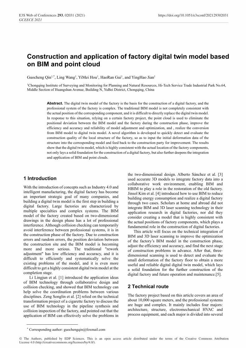
Figure 1. Technical flow chart
The main technical route of this article is shown in
Figure 1. It mainly consists of three major components. The first is the BIM technology in the blue area, the second is the 3D laser scanning technology in the red area, and the third is the fusion application of the two in the yellow area. The three finally converge in the creation of the digital twin model.
3 Original model self-check Before the start of construction, the 3D modeling software used to create the original BIM model of the factory was Bentley's AECOsim Building Designer (AECO) [6]. The software is more popular in the industrial field in Europe, and is often used in the design, analysis, construction, etc. of automotive manufacturing plants.
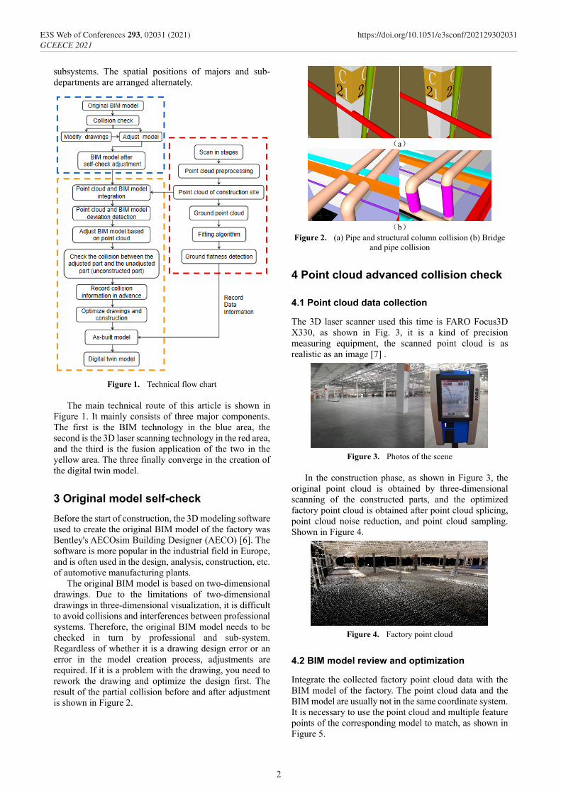
The original BIM model is based on two-dimensional drawings. Due to the limitations of two-dimensional drawings in three-dimensional visualization, it is difficult to avoid collisions and interferences between professional systems. Therefore, the original BIM model needs to be checked in turn by professional and sub-system. Regardless of whether it is a drawing design error or an error in the model creation process, adjustments are required. If it is a problem with the drawing, you need to rework the drawing and optimize the design first. The result of the partial collision before and after adjustment is shown in Figure 2.
(a)
(b)
Figure 2. (a) Pipe and structural column collision (b) Bridge and pipe collision
4 Point cloud advanced collision check
4.1 Point cloud data collection
The 3D laser scanner used this time is FARO Focus3D X330, as shown in Fig. 3, it is a kind of precision measuring equipment, the scanned point cloud is as realistic as an image [7] .
Figure 3. Photos of the scene
In the construction phase, as shown in Figure 3, the
original point cloud is obtained by three-dimensional scanning of the constructed parts, and the optimized factory point cloud is obtained after point cloud splicing, point cloud noise reduction, and point cloud sampling. Shown in Figure 4.
Figure 4. Factory point cloud
4.2 BIM model review and optimization
Integrate the collected factory point cloud data with the BIM model of the factory. The point cloud data and the BIM model are usually not in the same coordinate system. It is necessary to use the point cloud and multiple feature points of the corresponding model to match, as shown in Figure 5.
2
E3S Web of Conferences 293, 02031 (2021) https://doi.org/10.1051/e3sconf/202129302031GCEECE 2021
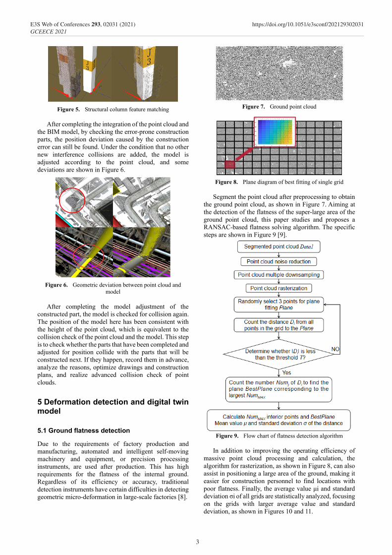
Figure 5. Structural column feature matching
After completing the integration of the point cloud and
the BIM model, by checking the error-prone construction parts, the position deviation caused by the construction error can still be found. Under the condition that no other new interference collisions are added, the model is adjusted according to the point cloud, and some deviations are shown in Figure 6.
Figure 6. Geometric deviation between point cloud and
model After completing the model adjustment of the
constructed part, the model is checked for collision again. The position of the model here has been consistent with the height of the point cloud, which is equivalent to the collision check of the point cloud and the model. This step is to check whether the parts that have been completed and adjusted for position collide with the parts that will be constructed next. If they happen, record them in advance, analyze the reasons, optimize drawings and construction plans, and realize advanced collision check of point clouds.
5 Deformation detection and digital twin model
5.1 Ground flatness detection
Due to the requirements of factory production and manufacturing, automated and intelligent self-moving machinery and equipment, or precision processing instruments, are used after production. This has high requirements for the flatness of the internal ground. Regardless of its efficiency or accuracy, traditional detection instruments have certain difficulties in detecting geometric micro-deformation in large-scale factories [8].
Figure 7. Ground point cloud
Figure 8. Plane diagram of best fitting of single grid
Segment the point cloud after preprocessing to obtain
the ground point cloud, as shown in Figure 7. Aiming at the detection of the flatness of the super-large area of the ground point cloud, this paper studies and proposes a RANSAC-based flatness solving algorithm. The specific steps are shown in Figure 9 [9].
Figure 9. Flow chart of flatness detection algorithm
In addition to improving the operating efficiency of
massive point cloud processing and calculation, the algorithm for rasterization, as shown in Figure 8, can also assist in positioning a large area of the ground, making it easier for construction personnel to find locations with poor flatness. Finally, the average value μi and standard deviation σi of all grids are statistically analyzed, focusing on the grids with larger average value and standard deviation, as shown in Figures 10 and 11.
3
E3S Web of Conferences 293, 02031 (2021) https://doi.org/10.1051/e3sconf/202129302031GCEECE 2021
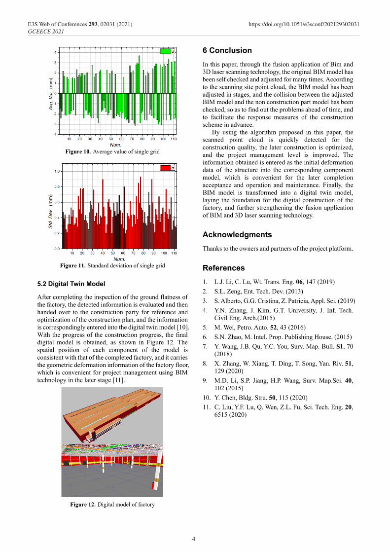
Figure 10. Average value of single grid
Figure 11. Standard deviation of single grid
5.2 Digital Twin Model
After completing the inspection of the ground flatness of the factory, the detected information is evaluated and then handed over to the construction party for reference and optimization of the construction plan, and the information is correspondingly entered into the digital twin model [10]. With the progress of the construction progress, the final digital model is obtained, as shown in Figure 12. The spatial position of each component of the model is consistent with that of the completed factory, and it carries the geometric deformation information of the factory floor, which is convenient for project management using BIM technology in the later stage [11].
Figure 12. Digital model of factory
6 Conclusion In this paper, through the fusion application of Bim and 3D laser scanning technology, the original BIM model has been self checked and adjusted for many times. According to the scanning site point cloud, the BIM model has been adjusted in stages, and the collision between the adjusted BIM model and the non construction part model has been checked, so as to find out the problems ahead of time, and to facilitate the response measures of the construction scheme in advance.
By using the algorithm proposed in this paper, the scanned point cloud is quickly detected for the construction quality, the later construction is optimized, and the project management level is improved. The information obtained is entered as the initial deformation data of the structure into the corresponding component model, which is convenient for the later completion acceptance and operation and maintenance. Finally, the BIM model is transformed into a digital twin model, laying the foundation for the digital construction of the factory, and further strengthening the fusion application of BIM and 3D laser scanning technology.
Acknowledgments Thanks to the owners and partners of the project platform.
References 1. L.J. Li, C. Lu, Wt. Trans. Eng. 06, 147 (2019) 2. S.L. Zeng, Ent. Tech. Dev. (2013) 3. S. Alberto, G.G. Cristina, Z. Patricia, Appl. Sci. (2019) 4. Y.N. Zhang, J. Kim, G.T. University, J. Inf. Tech.
Civil Eng. Arch.(2015) 5. M. Wei, Petro. Auto. 52, 43 (2016) 6. S.N. Zhao, M. Intel. Prop. Publishing House. (2015) 7. Y. Wang, J.B. Qu, Y.C. You, Surv. Map. Bull. S1, 70
(2018) 8. X. Zhang, W. Xiang, T. Ding, T. Song, Yan. Riv. 51,
129 (2020) 9. M.D. Li, S.P. Jiang, H.P. Wang, Surv. Map.Sci. 40,
102 (2015) 10. Y. Chen, Bldg. Stru. 50, 115 (2020) 11. C. Liu, Y.F. Lu, Q. Wen, Z.L. Fu, Sci. Tech. Eng. 20,
6515 (2020)
4
E3S Web of Conferences 293, 02031 (2021) https://doi.org/10.1051/e3sconf/202129302031GCEECE 2021