configuring clocking and timing - cisco · clocking is typically distributed from the core network...
TRANSCRIPT
Cisco MWR 2941 Mobile Wireless Edge Router So
OL-23889-01
C H A P T E R 16
Configuring Clocking and TimingClock synchronization is important for a variety of applications, including synchronization of radio cell towers. While legacy TDM protocols incorporate timing features, packet-switched networks such as Ethernet do not natively include these features. The Cisco MWR 2941 supports legacy TDM technologies while supporting a variety of technologies that distribute clocking information over packet-switched networks.
The following sections describe the clocking and timing features available on the Cisco MWR 2941.
• Network Clocking Overview
• Configuring Clocking and Timing
• Clocking Sample Configurations
Network Clocking OverviewClocking is typically distributed from the core network outward to the BTS or Node B at the network edge. The Cisco MWR 2941 receives and transmits clocking information using any of the following ports:
• T1/E1
• Ethernet (GigabitEthernet and FastEthernet)
• DSL
• BITS/SYNC port
• 1PPS
• 1.544Mhz
• 2.048Mhz
• 10Mhz
The Cisco MWR 2941 supports the following clocking types:
• Precision Timing Protocol (PTP)
• Pseudowire-Based Clocking
• Synchronous Ethernet
16-1ftware Configuration Guide, Release 15.1(1)MR
Chapter 16 Configuring Clocking and Timing Network Clocking Overview
Precision Timing Protocol (PTP)
The Cisco MWR 2941 supports the Precision Time Protocol (PTP) as defined by the IEEE 1588-2008 standard. PTP provides for accurate time synchronization on over packet-switched networks. Nodes within a PTP network can act in one of the following roles:
• Grandmaster—A device on the network physically attached to the primary time source. All other clocks are ultimately synchronized to the grandmaster clock.
• Ordinary clock—An ordinary clock is a 1588 clock with a single PTP port that can serve in one of the following roles:
– Master mode—Distributes timing information over the network to one or more slave clocks, thus allowing the slave to synchronize its clock to the master.
– Slave mode—Synchronizes its clock to a master clock. You can enable slave clocking on up to two interfaces simultaneously in order to connect to two different master clocks.
• Boundary clock—The device participates in selecting the best master clock and can act as the master clock if no better clocks are detected.
• Transparent clock—A device such as a switch that calculates the time it requires to forward traffic and updates the PTP time correction field to account for the delay, making the device transparent in terms of timing calculations.
Note The Cisco MWR 2941 does not currently act as a transparent clock.
Note The Cisco MWR 2941 does not currently act as a boundary clock.
Note The 1588-2008 standard defines other clocking devices that are not described here.
PTP Domains
PTP devices use a best master clock algorithm to determine the most accurate clock on a network and construct a clocking hierarchy based on the grandmaster clock. A given clocking hierarchy is called a PTP domain.
Clock Synchronization
PTP master devices periodically launch an exchange of messages with slave devices to help each slave clock recompute the offset between its clock and the master clock. Periodic clock synchronization mitigates any drift between the master and slave clocks.
PTP Redundancy
The Cisco MWR 2941 supports the multicast- and unicast-based timing as specified in the 1588-2008 standard. The Cisco MWR 2941 can use multicast routing to establish redundant paths between an external PTP client and one or more PTP multicast master clocks. The Cisco MWR 2941 functions as a multicast router only for PTP traffic and only allows multicast traffic to pass from the PTP master clocks to the PTP client (the PTP client can send unicast traffic).
16-2Cisco MWR 2941 Mobile Wireless Edge Router Software Configuration Guide, Release 15.1(1)MR
OL-23889-01
Chapter 16 Configuring Clocking and Timing Network Clocking Overview
When configured as a multicast PTP router, the Cisco MWR 2941 selects the best path toward a Rendezvous Point (RP) using the active routing protocol, sends a Cisco Protocol Independent Multicast (PIM) join message to the RP, and forwards PTP multicast messages to the PTP client. The Cisco MWR 2941 also supports PIM forwarding. For instructions on how to configure PTP redundancy using multicast, see Configuring PTP Redundancy, page 16-10.
Hot Standby Master Clock
The Cisco MWR 2941 supports a hot standby master clock for PTP clocking; the Cisco MWR 2941 selects the best clock source between two PTP master clocks and switches dynamically between them if the clock quality of the standby clock is greater than that of the current master clock. For instructions on how to configure a hot standby master clock, see Configuring PTP Clocking.
Hybrid Clocking
The Cisco MWR 2941 supports a hybrid clocking mode that uses clock frequency obtained from the synchronous Ethernet port while using phase (ToD or 1PPS) obtained using PTP. For instructions on how to configure hybrid clocking, see Configuring PTP Clocking.
Pseudowire-Based Clocking
Pseudowire-based clocking allows the Cisco MWR 2941 router to
• Transmit and receive clocking information over a pseudowire interface
• Receive clocking over a virtual pseudowire interface.
The Cisco MWR 2941 can transmit clocking information within packet headers (in-band) or as a separate packet stream (out-of-band).
Pseudowire-based clocking also supports adaptive clock recovery (ACR), which allows the Cisco MWR 2941 to recover clocking from the headers of a packet stream. For instructions on how to configure pseudowire-based clocking, see Configuring Clocking and Timing.
Synchronous Ethernet
Synchronous Ethernet is a timing technology that allows the Cisco MWR 2941 to transport frequency and time information over Ethernet. Because frequency and time are embedded in Ethernet packets, synchronous Ethernet must be supported by each network element in the synchronization path. Synchronous Ethernet is defined in the ITU-T G.781, G.8261, G.8262, and G.8264, Telcordia GR-253-CORE, and Telcordia GR-1244-CORE standards.
You can use synchronous Ethernet in conjunction with an external timing technology such as GPS to synchronize timing across the network. For instructions on how to configure synchronous Ethernet, see Configuring Clocking and Timing.
Synchronous Ethernet ESMC and SSM
The Cisco MWR 2941 supports Ethernet Synchronization Message Channel (ESMC) and Synchronization Status Message (SSM) to provide clock synchronization on Synchronous Ethernet. For more information about Ethernet ESMC and SSM, see Chapter 17, “Configuring Synchronous Ethernet ESMC and SSM.”
16-3Cisco MWR 2941 Mobile Wireless Edge Router Software Configuration Guide, Release 15.1(1)MR
OL-23889-01
Chapter 16 Configuring Clocking and Timing Configuring Clocking and Timing
Configuring Clocking and TimingThe Cisco MWR 2941 supports the following network clocking types:
• Precision Time Protocol (PTP)—Clocking and clock recovery based on the IEEE 1588-2008 standard; allows the Cisco MWR 2941 router to receive clocking from another PTP-enabled device or provide clocking to a PTP-enabled device. To configure PTP clocking, see Configuring PTP Clocking. If you want to enable PTP redundancy, you must also complete the steps in the Configuring PTP Redundancy section.
• Pseudowire-based clocking—Allows the Cisco MWR 2941 router to use clocking using a pseudowire or virtual pseudowire interface. Pseudowire-based clocking supports adaptive clock recovery, which allows the Cisco MWR 2941 to recover clocking from the headers of a packet stream. To configure pseudowire-based clocking, see Configuring Pseudowire-Based Clocking with Adaptive Clock Recovery.
• Synchronous Ethernet—Allows the network to transport frequency and time information over Ethernet. To configure synchronous Ethernet, see Configuring Synchronous Ethernet.
• Verifying Clock Settings—To verify a clocking configuration, see Verifying Clock-Related Settings.
Note The Cisco MWR 2941 does not support the use of PTP and PWE-based clocking at the same time.
Configuring PTP Clocking
This section describes how to configure PTP-based clocking on the Cisco MWR 2941. For more information about the PTP commands, see the Cisco MWR 2941 Mobile Wireless Edge Router IOS Command Reference, Release 15.0(1)MR.
Note The settings shown in this section are an example only; you must determine the appropriate PTP settings based upon your network clocking design.
Note The configuration sections describing the 1PPS and 10Mhz timing ports only apply to the Cisco MWR 2941-DC-A; the Cisco MWR-DC router does not have these timing ports.
16-4Cisco MWR 2941 Mobile Wireless Edge Router Software Configuration Guide, Release 15.1(1)MR
OL-23889-01
Chapter 16 Configuring Clocking and Timing Configuring Clocking and Timing
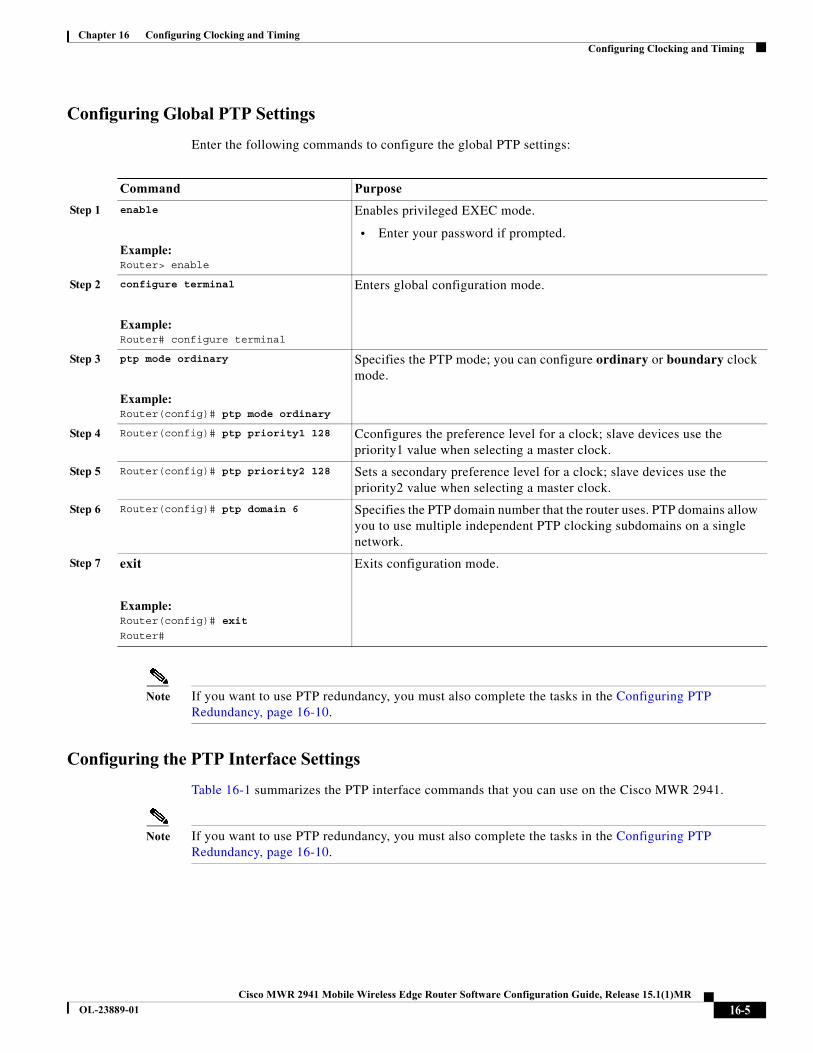
Configuring Global PTP Settings
Enter the following commands to configure the global PTP settings:
Note If you want to use PTP redundancy, you must also complete the tasks in the Configuring PTP Redundancy, page 16-10.
Configuring the PTP Interface Settings
Table 16-1 summarizes the PTP interface commands that you can use on the Cisco MWR 2941.
Note If you want to use PTP redundancy, you must also complete the tasks in the Configuring PTP Redundancy, page 16-10.
Command Purpose
Step 1 enable
Example:Router> enable
Enables privileged EXEC mode.
• Enter your password if prompted.
Step 2 configure terminal
Example:Router# configure terminal
Enters global configuration mode.
Step 3 ptp mode ordinary
Example:Router(config)# ptp mode ordinary
Specifies the PTP mode; you can configure ordinary or boundary clock mode.
Step 4 Router(config)# ptp priority1 128 Cconfigures the preference level for a clock; slave devices use the priority1 value when selecting a master clock.
Step 5 Router(config)# ptp priority2 128 Sets a secondary preference level for a clock; slave devices use the priority2 value when selecting a master clock.
Step 6 Router(config)# ptp domain 6 Specifies the PTP domain number that the router uses. PTP domains allow you to use multiple independent PTP clocking subdomains on a single network.
Step 7 exit
Example:Router(config)# exit
Router#
Exits configuration mode.
16-5Cisco MWR 2941 Mobile Wireless Edge Router Software Configuration Guide, Release 15.1(1)MR
OL-23889-01
Chapter 16 Configuring Clocking and Timing Configuring Clocking and Timing
The following examples demonstrate how to use these commands to configure each of the PTP modes. Use the appropriate section based on the PTP mode that you want to configure on the Cisco MWR 2941.
• PTP multicast master mode—Sets the Cisco MWR 2941 to act as the master PTP clock. Multicast specifies that the router sends PTP messages to all the slaves listening on the PTP multicast group.
Note PTP master mode is intended for trial use only and is not for use in a production network.
Router(config)# interface Vlan10Router(config-if)# ip address 192.168.52.38 255.255.255.0Router(config-if)# ip igmp join-group 224.0.1.129Router(config-if)# ptp announce interval 0Router(config-if)# ptp sync interval -6Router(config-if)# ptp delay-req interval -4Router(config-if)# ptp master multicastRouter(config-if)# ptp enable
• PTP multicast slave mode—Sets the Cisco MWR 2941 to receive clocking from a PTP master device in multicast mode.
Router(config)# interface Vlan10Router(config-if)# ip address 192.168.52.38 255.255.255.0Router(config-if)# ip igmp join-group 224.0.1.129
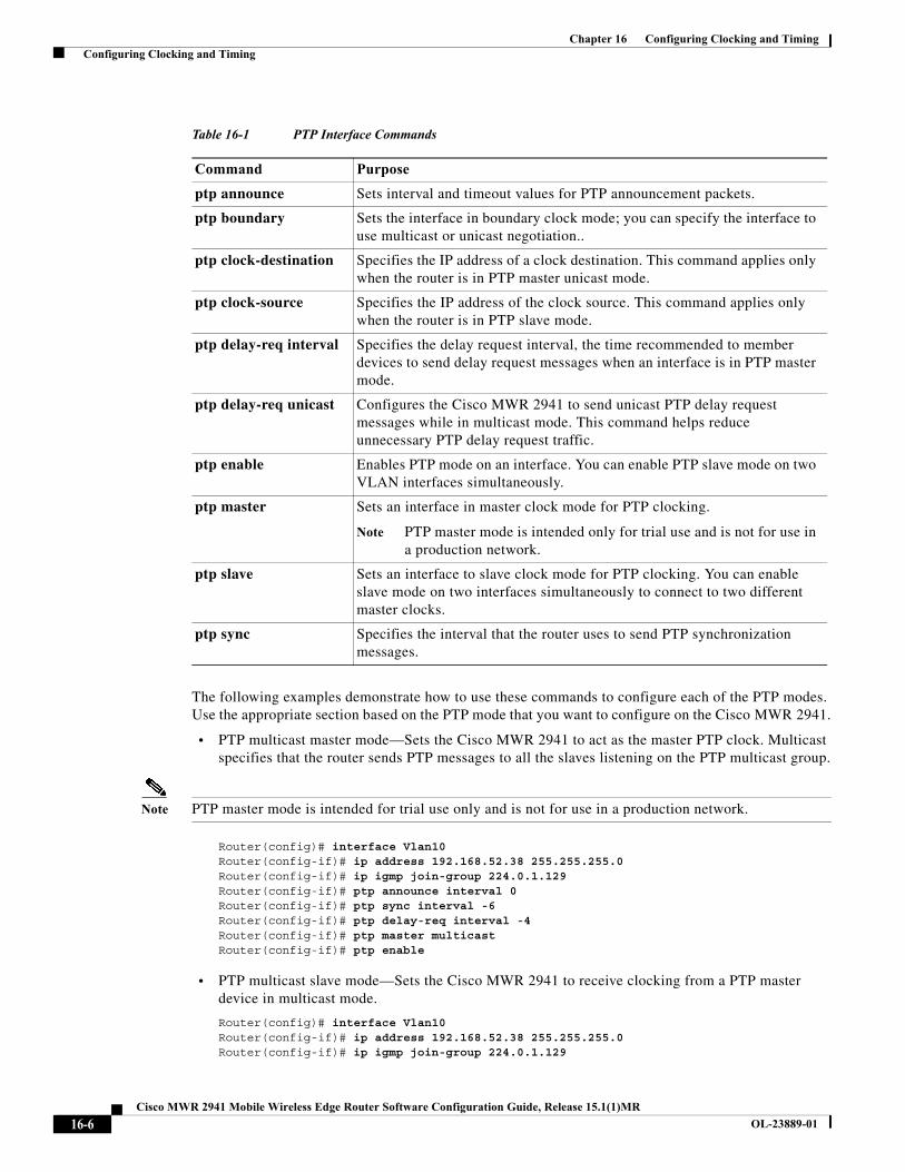
Table 16-1 PTP Interface Commands
Command Purpose
ptp announce Sets interval and timeout values for PTP announcement packets.
ptp boundary Sets the interface in boundary clock mode; you can specify the interface to use multicast or unicast negotiation..
ptp clock-destination Specifies the IP address of a clock destination. This command applies only when the router is in PTP master unicast mode.
ptp clock-source Specifies the IP address of the clock source. This command applies only when the router is in PTP slave mode.
ptp delay-req interval Specifies the delay request interval, the time recommended to member devices to send delay request messages when an interface is in PTP master mode.
ptp delay-req unicast Configures the Cisco MWR 2941 to send unicast PTP delay request messages while in multicast mode. This command helps reduce unnecessary PTP delay request traffic.
ptp enable Enables PTP mode on an interface. You can enable PTP slave mode on two VLAN interfaces simultaneously.
ptp master Sets an interface in master clock mode for PTP clocking.
Note PTP master mode is intended only for trial use and is not for use in a production network.
ptp slave Sets an interface to slave clock mode for PTP clocking. You can enable slave mode on two interfaces simultaneously to connect to two different master clocks.
ptp sync Specifies the interval that the router uses to send PTP synchronization messages.
16-6Cisco MWR 2941 Mobile Wireless Edge Router Software Configuration Guide, Release 15.1(1)MR
OL-23889-01
Chapter 16 Configuring Clocking and Timing Configuring Clocking and Timing
Router(config-if)# ptp announce interval 0Router(config-if)# ptp sync interval -6Router(config-if)# ptp delay-req interval -4Router(config-if)# ptp slave multicastRouter(config-if)# ptp enable
• PTP multicast slave mode (with hybrid clocking)—Sets the Cisco MWR 2941 to receive phase from a PTP master device in multicast mode while using clock frequency obtained from the synchronous Ethernet port.
Router(config)# interface Vlan10Router(config-if)# ip address 192.168.52.38 255.255.255.0Router(config-if)# ip igmp join-group 224.0.1.129Router(config-if)# ptp announce interval 0Router(config-if)# ptp sync interval -6Router(config-if)# ptp delay-req interval -4Router(config-if)# ptp slave multicast hybridRouter(config-if)# ptp enable
Note You can use the ptp delay-req unicast command to set the Cisco MWR 2941 to send unicast PTP Delay_Req messages while in multicast mode in order to eliminate unnecessary multicast traffic. For more information about this command, see the Cisco MWR 2941 Mobile Wireless Edge Router IOS Command Reference, Release 15.0(1)MR.
• PTP unicast master mode—Sets the Cisco MWR 2941 to act as the master PTP clock. Unicast specifies that the router sends PTP messages to a single slave host.
Router(config)# interface Vlan2Router(config-if)# ip address 192.168.52.38 255.255.255.0Router(config-if)# ptp announce interval 0Router(config-if)# ptp sync interval -6Router(config-if)# ptp delay-req interval -4Router(config-if)# ptp master unicastRouter(config-if)# ptp clock-destination 192.168.52.201Router(config-if)# ptp enable
• PTP unicast master mode (with negotiation enabled)—Sets the Cisco MWR 2941 to send clocking to a single PTP slave device; the router allows the slave devices to negotiate their master clock device. When in the router is in PTP unicast master mode, you can specify up to 128 PTP clock destination devices.
Note If you set the router to PTP master unicast mode with negotiation, you do not specify PTP clock destinations because the router negotiates to determine the IP addresses of the PTP slave devices.
Note We recommend that you determine the number of destination devices to assign to a master clock based on traffic rates and available bandwidth.
Router(config)# interface Vlan2Router(config-if)# ip address 192.168.52.38 255.255.255.0Router(config-if)# ptp announce interval 0Router(config-if)# ptp sync interval -6Router(config-if)# ptp delay-req interval -4Router(config-if)# ptp master unicast negotiationRouter(config-if)# ptp enable
16-7Cisco MWR 2941 Mobile Wireless Edge Router Software Configuration Guide, Release 15.1(1)MR
OL-23889-01
Chapter 16 Configuring Clocking and Timing Configuring Clocking and Timing
• PTP unicast slave mode—Sets the Cisco MWR 2941 to receive clocking from a single PTP master device.
Router(config)# interface Vlan2Router(config-if)# ip address 192.168.52.38 255.255.255.0Router(config-if)# ptp announce interval 3Router(config-if)# ptp announce timeout 2Router(config-if)# ptp sync interval -6Router(config-if)# ptp delay-req interval -4Router(config-if)# ptp slave unicastRouter(config-if)# ptp clock-source 192.168.52.10Router(config-if)# ptp enable
• PTP unicast slave mode (with negotiation enabled)—Sets the Cisco MWR 2941 to receive clocking from a PTP master device; the router negotiates between up to 128 PTP master devices.
Router(config)# interface Vlan2Router(config-if)# ip address 192.168.52.38 255.255.255.0Router(config-if)# ptp announce interval 3Router(config-if)# ptp announce timeout 2Router(config-if)# ptp sync interval -6Router(config-if)# ptp delay-req interval -4Router(config-if)# ptp slave unicast negotiationRouter(config-if)# ptp clock-source 192.168.52.10Router(config-if)# ptp enable
• PTP unicast slave mode (with hybrid clocking)—Sets the Cisco MWR 2941 to receive phase (ToD or 1PPS) from a single PTP master device while using clock frequency obtained from the synchronous Ethernet port.
Router(config)# interface Vlan2Router(config-if)# ip address 192.168.52.38 255.255.255.0Router(config-if)# ptp announce interval 3Router(config-if)# ptp announce timeout 2Router(config-if)# ptp sync interval -6Router(config-if)# ptp delay-req interval -4Router(config-if)# ptp slave unicast negotiation hybridRouter(config-if)# ptp clock-source 192.168.52.10Router(config-if)# ptp enable
• PTP unicast slave mode (with hot standby master clock)—Sets the Cisco MWR 2941 to receive clocking from a single PTP master device and enables a standby master clock. When you enable a standby master clock, the Cisco MWR 2941 selects the best clock source between two PTP master clocks and switches dynamically between them if the clock quality of the standby clock is greater than that of the current master clock. If you define a standby master clock, both clock sources must be in the same VLAN. Setting a standby master clock in unicast mode is optional.
Router(config)# interface Vlan2Router(config-if)# ip address 192.168.52.38 255.255.255.0Router(config-if)# ptp announce interval 3Router(config-if)# ptp announce timeout 2Router(config-if)# ptp sync interval -6Router(config-if)# ptp delay-req interval -4Router(config-if)# ptp slave unicast negotiation hybrid Router(config-if)# ptp clock-source 192.168.52.10Router(config-if)# ptp clock-source 192.168.52.150Router(config-if)# ptp enable
16-8Cisco MWR 2941 Mobile Wireless Edge Router Software Configuration Guide, Release 15.1(1)MR
OL-23889-01
Chapter 16 Configuring Clocking and Timing Configuring Clocking and Timing
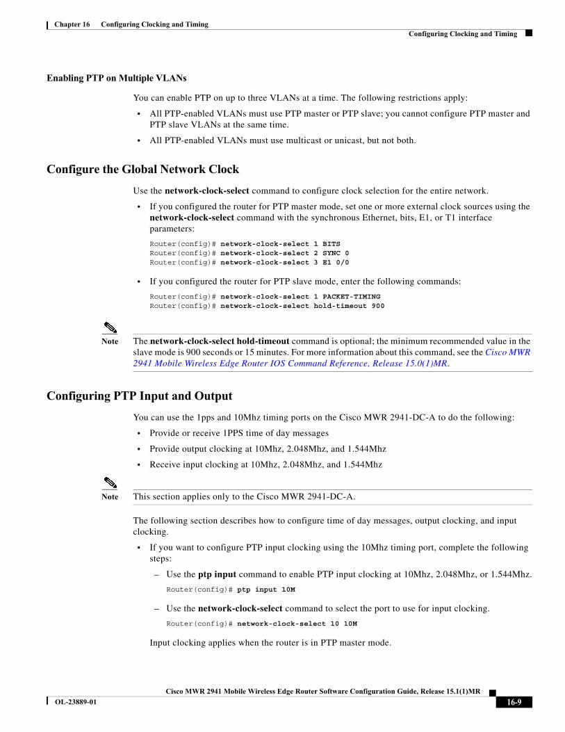
Enabling PTP on Multiple VLANs
You can enable PTP on up to three VLANs at a time. The following restrictions apply:
• All PTP-enabled VLANs must use PTP master or PTP slave; you cannot configure PTP master and PTP slave VLANs at the same time.
• All PTP-enabled VLANs must use multicast or unicast, but not both.
Configure the Global Network Clock
Use the network-clock-select command to configure clock selection for the entire network.
• If you configured the router for PTP master mode, set one or more external clock sources using the network-clock-select command with the synchronous Ethernet, bits, E1, or T1 interface parameters:
Router(config)# network-clock-select 1 BITSRouter(config)# network-clock-select 2 SYNC 0Router(config)# network-clock-select 3 E1 0/0
• If you configured the router for PTP slave mode, enter the following commands:
Router(config)# network-clock-select 1 PACKET-TIMINGRouter(config)# network-clock-select hold-timeout 900
Note The network-clock-select hold-timeout command is optional; the minimum recommended value in the slave mode is 900 seconds or 15 minutes. For more information about this command, see the Cisco MWR 2941 Mobile Wireless Edge Router IOS Command Reference, Release 15.0(1)MR.
Configuring PTP Input and Output
You can use the 1pps and 10Mhz timing ports on the Cisco MWR 2941-DC-A to do the following:
• Provide or receive 1PPS time of day messages
• Provide output clocking at 10Mhz, 2.048Mhz, and 1.544Mhz
• Receive input clocking at 10Mhz, 2.048Mhz, and 1.544Mhz
Note This section applies only to the Cisco MWR 2941-DC-A.
The following section describes how to configure time of day messages, output clocking, and input clocking.
• If you want to configure PTP input clocking using the 10Mhz timing port, complete the following steps:
– Use the ptp input command to enable PTP input clocking at 10Mhz, 2.048Mhz, or 1.544Mhz.
Router(config)# ptp input 10M
– Use the network-clock-select command to select the port to use for input clocking.
Router(config)# network-clock-select 10 10M
Input clocking applies when the router is in PTP master mode.
16-9Cisco MWR 2941 Mobile Wireless Edge Router Software Configuration Guide, Release 15.1(1)MR
OL-23889-01
Chapter 16 Configuring Clocking and Timing Configuring Clocking and Timing
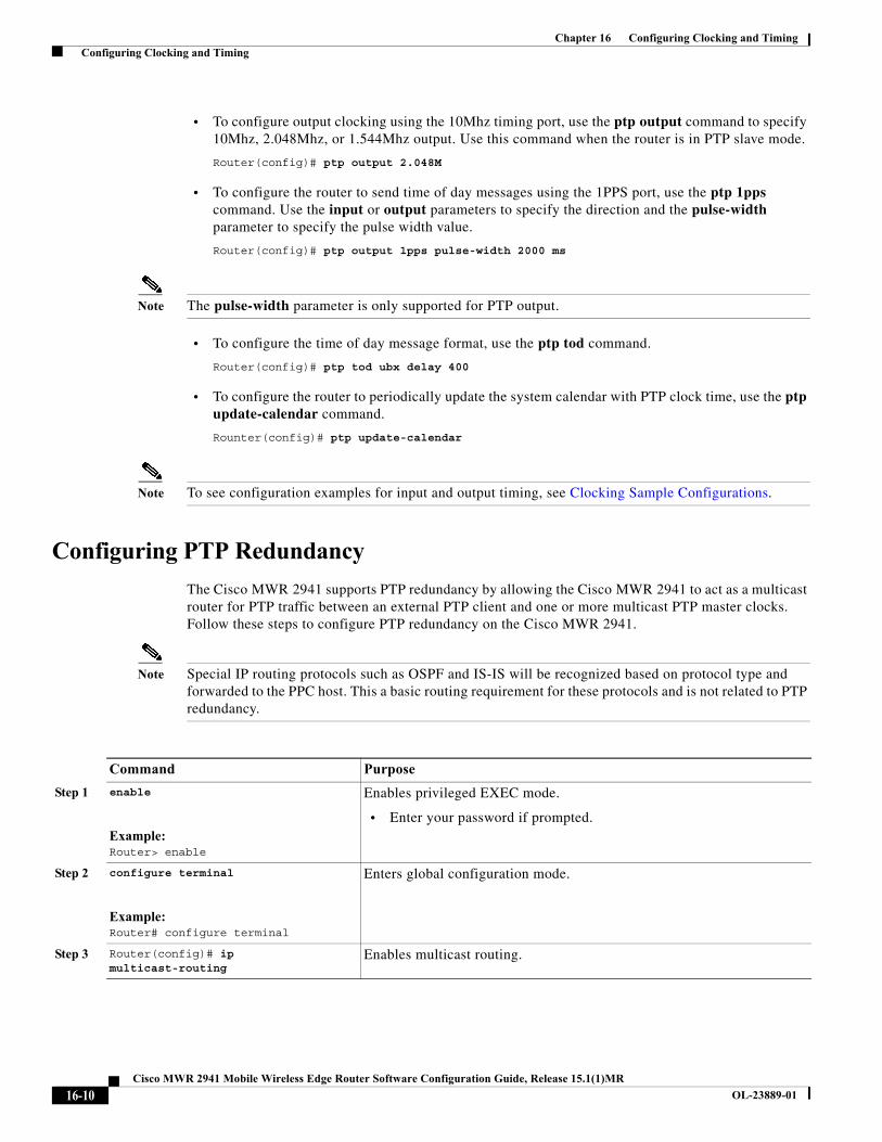
• To configure output clocking using the 10Mhz timing port, use the ptp output command to specify 10Mhz, 2.048Mhz, or 1.544Mhz output. Use this command when the router is in PTP slave mode.
Router(config)# ptp output 2.048M
• To configure the router to send time of day messages using the 1PPS port, use the ptp 1pps command. Use the input or output parameters to specify the direction and the pulse-width parameter to specify the pulse width value.
Router(config)# ptp output 1pps pulse-width 2000 ms
Note The pulse-width parameter is only supported for PTP output.
• To configure the time of day message format, use the ptp tod command.
Router(config)# ptp tod ubx delay 400
• To configure the router to periodically update the system calendar with PTP clock time, use the ptp update-calendar command.
Rounter(config)# ptp update-calendar
Note To see configuration examples for input and output timing, see Clocking Sample Configurations.
Configuring PTP Redundancy
The Cisco MWR 2941 supports PTP redundancy by allowing the Cisco MWR 2941 to act as a multicast router for PTP traffic between an external PTP client and one or more multicast PTP master clocks. Follow these steps to configure PTP redundancy on the Cisco MWR 2941.
Note Special IP routing protocols such as OSPF and IS-IS will be recognized based on protocol type and forwarded to the PPC host. This a basic routing requirement for these protocols and is not related to PTP redundancy.
Command Purpose
Step 1 enable
Example:Router> enable
Enables privileged EXEC mode.
• Enter your password if prompted.
Step 2 configure terminal
Example:Router# configure terminal
Enters global configuration mode.
Step 3 Router(config)# ip multicast-routing
Enables multicast routing.
16-10Cisco MWR 2941 Mobile Wireless Edge Router Software Configuration Guide, Release 15.1(1)MR
OL-23889-01
Chapter 16 Configuring Clocking and Timing Configuring Clocking and Timing
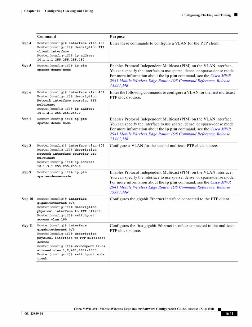
Step 4 Router(config)# interface vlan 100Router(config-if)# description PTP client interfaceRouter(config-if)# ip address 10.1.1.1 255.255.255.252
Enter these commands to configure a VLAN for the PTP client.
Step 5 Router(config-if)# ip pim sparse-dense-mode
Enables Protocol Independent Multicast (PIM) on the VLAN interface. You can specify the interface to use sparse, dense, or sparse-dense mode. For more information about the ip pim command, see the Cisco MWR 2941 Mobile Wireless Edge Router IOS Command Reference, Release 15.0(1)MR.
Step 6 Router(config)# interface vlan 401Router(config-if)# description Network interface sourcing PTP multicastRouter(config-if)# ip address 10.1.2.1 255.255.255.0
Enter the following commands to configure a VLAN for the first multicast PTP clock source.
Step 7 Router(config-if)# ip pim sparse-dense-mode
Enables Protocol Independent Multicast (PIM) on the VLAN interface. You can specify the interface to use sparse, dense, or sparse-dense mode. For more information about the ip pim command, see the Cisco MWR 2941 Mobile Wireless Edge Router IOS Command Reference, Release 15.0(1)MR.
Step 8 Router(config)# interface vlan 402Router(config-if)# description Network interface sourcing PTP multicastRouter(config-if)# ip address 10.1.3.1 255.255.255.0
Configure a VLAN for the second multicast PTP clock source.
Step 9 Router(config-if)# ip pim sparse-dense-mode
Enables Protocol Independent Multicast (PIM) on the VLAN interface. You can specify the interface to use sparse, dense, or sparse-dense mode. For more information about the ip pim command, see the Cisco MWR 2941 Mobile Wireless Edge Router IOS Command Reference, Release 15.0(1)MR.
Step 10 Router(config)# interface gigabitethernet 0/5Router(config-if)# description physical interface to PTP clientRouter(config-if)# switchport access vlan 100
Configures the gigabit Ethernet interface connected to the PTP client.
Step 11 Router(config)# interface gigabitethernet 0/0Router(config-if)# description physical interface to PTP multicast sourceRouter(config-if)# switchport trunk allowed vlan 1,2,401,1002-1005Router(config-if)# switchport mode trunk
Configures the first gigabit Ethernet interface connected to the multicast PTP clock source.
Command Purpose
16-11Cisco MWR 2941 Mobile Wireless Edge Router Software Configuration Guide, Release 15.1(1)MR
OL-23889-01
Chapter 16 Configuring Clocking and Timing Configuring Clocking and Timing
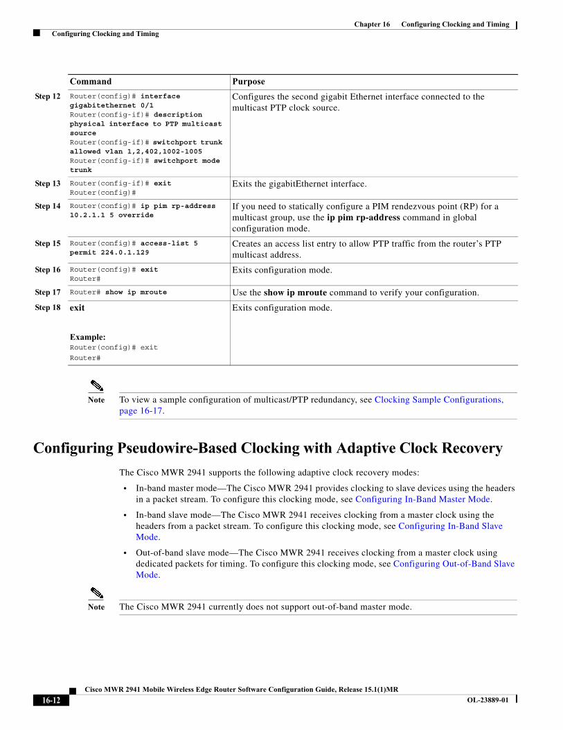
Note To view a sample configuration of multicast/PTP redundancy, see Clocking Sample Configurations, page 16-17.
Configuring Pseudowire-Based Clocking with Adaptive Clock Recovery
The Cisco MWR 2941 supports the following adaptive clock recovery modes:
• In-band master mode—The Cisco MWR 2941 provides clocking to slave devices using the headers in a packet stream. To configure this clocking mode, see Configuring In-Band Master Mode.
• In-band slave mode—The Cisco MWR 2941 receives clocking from a master clock using the headers from a packet stream. To configure this clocking mode, see Configuring In-Band Slave Mode.
• Out-of-band slave mode—The Cisco MWR 2941 receives clocking from a master clock using dedicated packets for timing. To configure this clocking mode, see Configuring Out-of-Band Slave Mode.
Note The Cisco MWR 2941 currently does not support out-of-band master mode.
Step 12 Router(config)# interface gigabitethernet 0/1Router(config-if)# description physical interface to PTP multicast sourceRouter(config-if)# switchport trunk allowed vlan 1,2,402,1002-1005Router(config-if)# switchport mode trunk
Configures the second gigabit Ethernet interface connected to the multicast PTP clock source.
Step 13 Router(config-if)# exitRouter(config)#
Exits the gigabitEthernet interface.
Step 14 Router(config)# ip pim rp-address 10.2.1.1 5 override
If you need to statically configure a PIM rendezvous point (RP) for a multicast group, use the ip pim rp-address command in global configuration mode.
Step 15 Router(config)# access-list 5 permit 224.0.1.129
Creates an access list entry to allow PTP traffic from the router’s PTP multicast address.
Step 16 Router(config)# exitRouter#
Exits configuration mode.
Step 17 Router# show ip mroute Use the show ip mroute command to verify your configuration.
Step 18 exit
Example:Router(config)# exit
Router#
Exits configuration mode.
Command Purpose
16-12Cisco MWR 2941 Mobile Wireless Edge Router Software Configuration Guide, Release 15.1(1)MR
OL-23889-01
Chapter 16 Configuring Clocking and Timing Configuring Clocking and Timing
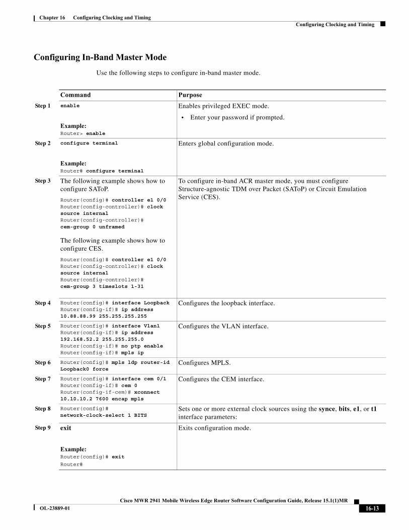
Configuring In-Band Master Mode
Use the following steps to configure in-band master mode.
Command Purpose
Step 1 enable
Example:Router> enable
Enables privileged EXEC mode.
• Enter your password if prompted.
Step 2 configure terminal
Example:Router# configure terminal
Enters global configuration mode.
Step 3 The following example shows how to configure SAToP.
Router(config)# controller e1 0/0Router(config-controller)# clock source internalRouter(config-controller)# cem-group 0 unframed
The following example shows how to configure CES.
Router(config)# controller e1 0/0Router(config-controller)# clock source internalRouter(config-controller)# cem-group 3 timeslots 1-31
To configure in-band ACR master mode, you must configure Structure-agnostic TDM over Packet (SAToP) or Circuit Emulation Service (CES).
Step 4 Router(config)# interface LoopbackRouter(config-if)# ip address 10.88.88.99 255.255.255.255
Configures the loopback interface.
Step 5 Router(config)# interface Vlan1Router(config-if)# ip address 192.168.52.2 255.255.255.0Router(config-if)# no ptp enableRouter(config-if)# mpls ip
Configures the VLAN interface.
Step 6 Router(config)# mpls ldp router-id Loopback0 force
Configures MPLS.
Step 7 Router(config)# interface cem 0/1Router(config-if)# cem 0Router(config-if-cem)# xconnect 10.10.10.2 7600 encap mpls
Configures the CEM interface.
Step 8 Router(config)# network-clock-select 1 BITS
Sets one or more external clock sources using the synce, bits, e1, or t1 interface parameters:
Step 9 exit
Example:Router(config)# exit
Router#
Exits configuration mode.
16-13Cisco MWR 2941 Mobile Wireless Edge Router Software Configuration Guide, Release 15.1(1)MR
OL-23889-01

Chapter 16 Configuring Clocking and Timing Configuring Clocking and Timing
Configuring In-Band Slave Mode
Use the following steps to configure in-band slave mode.
Command Purpose
Step 1 enable
Example:Router> enable
Enables privileged EXEC mode.
• Enter your password if prompted.
Step 2 configure terminal
Example:Router# configure terminal
Enters global configuration mode.
Step 3 The following example shows how to configure SAToP.
Router(config)# controller e1 0/0Router(config-controller)# clock source internalRouter(config-controller)# cem-group 0 unframed
The following example shows how to configure CES.
Router(config)# controller e1 0/0Router(config-controller)# clock source internalRouter(config-controller)# cem-group 3 timeslots 1-31
To configure in-band ACR slave mode, you must configure Structure-agnostic TDM over Packet (SAToP) or Circuit Emulation Service (CES).
Step 4 Router(config)# interface LoopbackRouter(config-if)# ip address 10.88.88.99 255.255.255.255
Configures the loopback interface.
Step 5 Router(config)# interface Vlan1Router(config-if)# ip address 192.168.52.10.2 255.255.255.0Router(config-if)# no ptp enableRouter(config-if)# mpls ip
Configures the VLAN interface.
Step 6 Router(config)# mpls ldp router-id Loopback0 force
Configures MPLS.
Step 7 Router(config)# interface cem 0/0Router(config-if)# cem 0Router(config-if-cem)# xconnect 10.10.10.2 7600 encap mpls
Configures the CEM interface.
Step 8 Router(config)# recovered-clock recovered adaptive cem 0 0 0
Configures adaptive clock recovery using a circuit emulation (CEM) interface.
16-14Cisco MWR 2941 Mobile Wireless Edge Router Software Configuration Guide, Release 15.1(1)MR
OL-23889-01
Chapter 16 Configuring Clocking and Timing Configuring Clocking and Timing
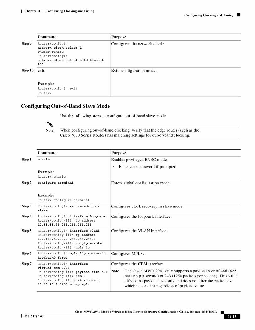
Configuring Out-of-Band Slave Mode
Use the following steps to configure out-of-band slave mode.
Note When configuring out-of-band clocking, verify that the edge router (such as the Cisco 7600 Series Router) has matching settings for out-of-band clocking.
Step 9 Router(config)# network-clock-select 1 PACKET-TIMINGRouter(config)# network-clock-select hold-timeout 900
Configures the network clock:
Step 10 exit
Example:Router(config)# exit
Router#
Exits configuration mode.
Command Purpose
Command Purpose
Step 1 enable
Example:Router> enable
Enables privileged EXEC mode.
• Enter your password if prompted.
Step 2 configure terminal
Example:Router# configure terminal
Enters global configuration mode.
Step 3 Router(config)# recovered-clock slave
Configures clock recovery in slave mode:
Step 4 Router(config)# interface LoopbackRouter(config-if)# ip address 10.88.88.99 255.255.255.255
Configures the loopback interface.
Step 5 Router(config)# interface Vlan1Router(config-if)# ip address 192.168.52.10.2 255.255.255.0Router(config-if)# no ptp enableRouter(config-if)# mpls ip
Configures the VLAN interface.
Step 6 Router(config)# mpls ldp router-id Loopback0 force
Configures MPLS.
Step 7 Router(config)# interface virtual-cem 0/24Router(config-if)# payload-size 486Router(config-if)# cem 0Router(config-if-cem)# xconnect 10.10.10.2 7600 encap mpls
Configures the CEM interface.
Note The Cisco MWR 2941 only supports a payload size of 486 (625 packets per second) or 243 (1250 packets per second). This value affects the payload size only and does not alter the packet size, which is constant regardless of payload value.
16-15Cisco MWR 2941 Mobile Wireless Edge Router Software Configuration Guide, Release 15.1(1)MR
OL-23889-01
Chapter 16 Configuring Clocking and Timing Configuring Clocking and Timing
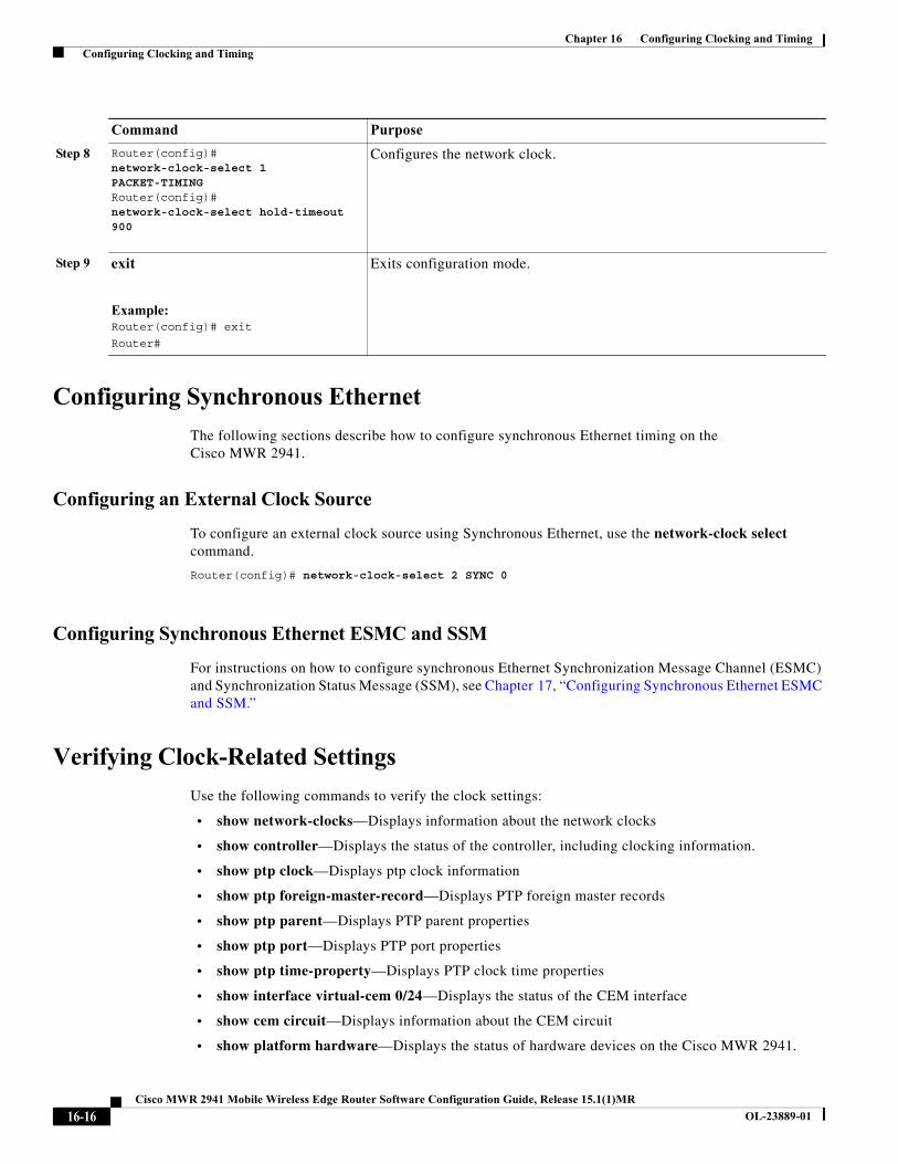
Configuring Synchronous Ethernet
The following sections describe how to configure synchronous Ethernet timing on the Cisco MWR 2941.
Configuring an External Clock Source
To configure an external clock source using Synchronous Ethernet, use the network-clock select command.
Router(config)# network-clock-select 2 SYNC 0
Configuring Synchronous Ethernet ESMC and SSM
For instructions on how to configure synchronous Ethernet Synchronization Message Channel (ESMC) and Synchronization Status Message (SSM), see Chapter 17, “Configuring Synchronous Ethernet ESMC and SSM.”
Verifying Clock-Related Settings
Use the following commands to verify the clock settings:
• show network-clocks—Displays information about the network clocks
• show controller—Displays the status of the controller, including clocking information.
• show ptp clock—Displays ptp clock information
• show ptp foreign-master-record—Displays PTP foreign master records
• show ptp parent—Displays PTP parent properties
• show ptp port—Displays PTP port properties
• show ptp time-property—Displays PTP clock time properties
• show interface virtual-cem 0/24—Displays the status of the CEM interface
• show cem circuit—Displays information about the CEM circuit
• show platform hardware—Displays the status of hardware devices on the Cisco MWR 2941.
Step 8 Router(config)# network-clock-select 1 PACKET-TIMINGRouter(config)# network-clock-select hold-timeout 900
Configures the network clock.
Step 9 exit
Example:Router(config)# exit
Router#
Exits configuration mode.
Command Purpose
16-16Cisco MWR 2941 Mobile Wireless Edge Router Software Configuration Guide, Release 15.1(1)MR
OL-23889-01
Chapter 16 Configuring Clocking and Timing Clocking Sample Configurations
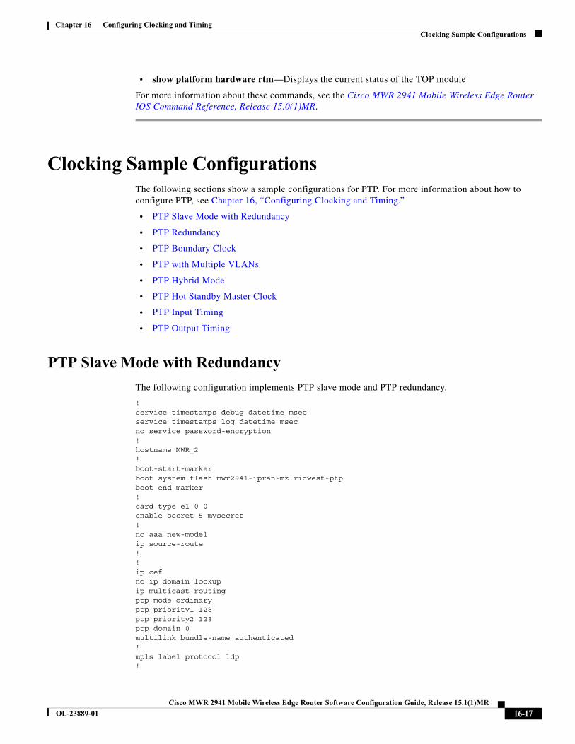
• show platform hardware rtm—Displays the current status of the TOP module
For more information about these commands, see the Cisco MWR 2941 Mobile Wireless Edge Router IOS Command Reference, Release 15.0(1)MR.
Clocking Sample ConfigurationsThe following sections show a sample configurations for PTP. For more information about how to configure PTP, see Chapter 16, “Configuring Clocking and Timing.”
• PTP Slave Mode with Redundancy
• PTP Redundancy
• PTP Boundary Clock
• PTP with Multiple VLANs
• PTP Hybrid Mode
• PTP Hot Standby Master Clock
• PTP Input Timing
• PTP Output Timing
PTP Slave Mode with Redundancy
The following configuration implements PTP slave mode and PTP redundancy.
!service timestamps debug datetime msecservice timestamps log datetime msecno service password-encryption!hostname MWR_2!boot-start-markerboot system flash mwr2941-ipran-mz.ricwest-ptpboot-end-marker!card type e1 0 0enable secret 5 mysecret!no aaa new-modelip source-route!!ip cefno ip domain lookupip multicast-routing ptp mode ordinary ptp priority1 128 ptp priority2 128 ptp domain 0 multilink bundle-name authenticated!mpls label protocol ldp!
16-17Cisco MWR 2941 Mobile Wireless Edge Router Software Configuration Guide, Release 15.1(1)MR
OL-23889-01
Chapter 16 Configuring Clocking and Timing Clocking Sample Configurations
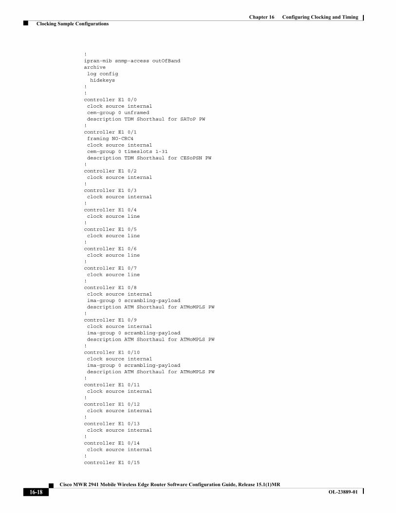
!ipran-mib snmp-access outOfBandarchive log config hidekeys!!controller E1 0/0 clock source internal cem-group 0 unframed description TDM Shorthaul for SAToP PW!controller E1 0/1 framing NO-CRC4 clock source internal cem-group 0 timeslots 1-31 description TDM Shorthaul for CESoPSN PW!controller E1 0/2 clock source internal!controller E1 0/3 clock source internal!controller E1 0/4 clock source line!controller E1 0/5 clock source line!controller E1 0/6 clock source line!controller E1 0/7 clock source line!controller E1 0/8 clock source internal ima-group 0 scrambling-payload description ATM Shorthaul for ATMoMPLS PW!controller E1 0/9 clock source internal ima-group 0 scrambling-payload description ATM Shorthaul for ATMoMPLS PW!controller E1 0/10 clock source internal ima-group 0 scrambling-payload description ATM Shorthaul for ATMoMPLS PW!controller E1 0/11 clock source internal!controller E1 0/12 clock source internal!controller E1 0/13 clock source internal!controller E1 0/14 clock source internal!controller E1 0/15
16-18Cisco MWR 2941 Mobile Wireless Edge Router Software Configuration Guide, Release 15.1(1)MR
OL-23889-01

Chapter 16 Configuring Clocking and Timing Clocking Sample Configurations
clock source internal!controller BITS applique E1!!pseudowire-class My_MPLS encapsulation mpls sequencing both!!interface Loopback0 ip address 10.1.1.22 255.255.255.255!interface GigabitEthernet0/0 switchport access vlan 11!interface GigabitEthernet0/1 switchport access vlan 12!interface GigabitEthernet0/2 switchport access vlan 30!interface GigabitEthernet0/3 shutdown!interface GigabitEthernet0/4 switchport mode trunk shutdown!interface GigabitEthernet0/5 switchport access vlan 5 duplex full speed 1000!interface CEM0/0 description SAToP PW no ip address cem 0 xconnect 10.10.10.36 5200 encapsulation mpls !!interface CEM0/1 description CESoPSN PW no ip address cem 0 xconnect 10.10.10.36 5201 encapsulation mpls !!interface ATM0/IMA0 description ATMoMPLS N:1 VCC Mode (where N=1) no ip address ima group-id 0 atm bandwidth dynamic no atm ilmi-keepalive pvc 1/32 l2transport encapsulation aal5 xconnect 10.10.10.36 5232 encapsulation mpls ! pvc 1/36 l2transport encapsulation aal0 xconnect 10.10.10.36 5236 encapsulation mpls ! pvc 1/37 l2transport
16-19Cisco MWR 2941 Mobile Wireless Edge Router Software Configuration Guide, Release 15.1(1)MR
OL-23889-01
Chapter 16 Configuring Clocking and Timing Clocking Sample Configurations
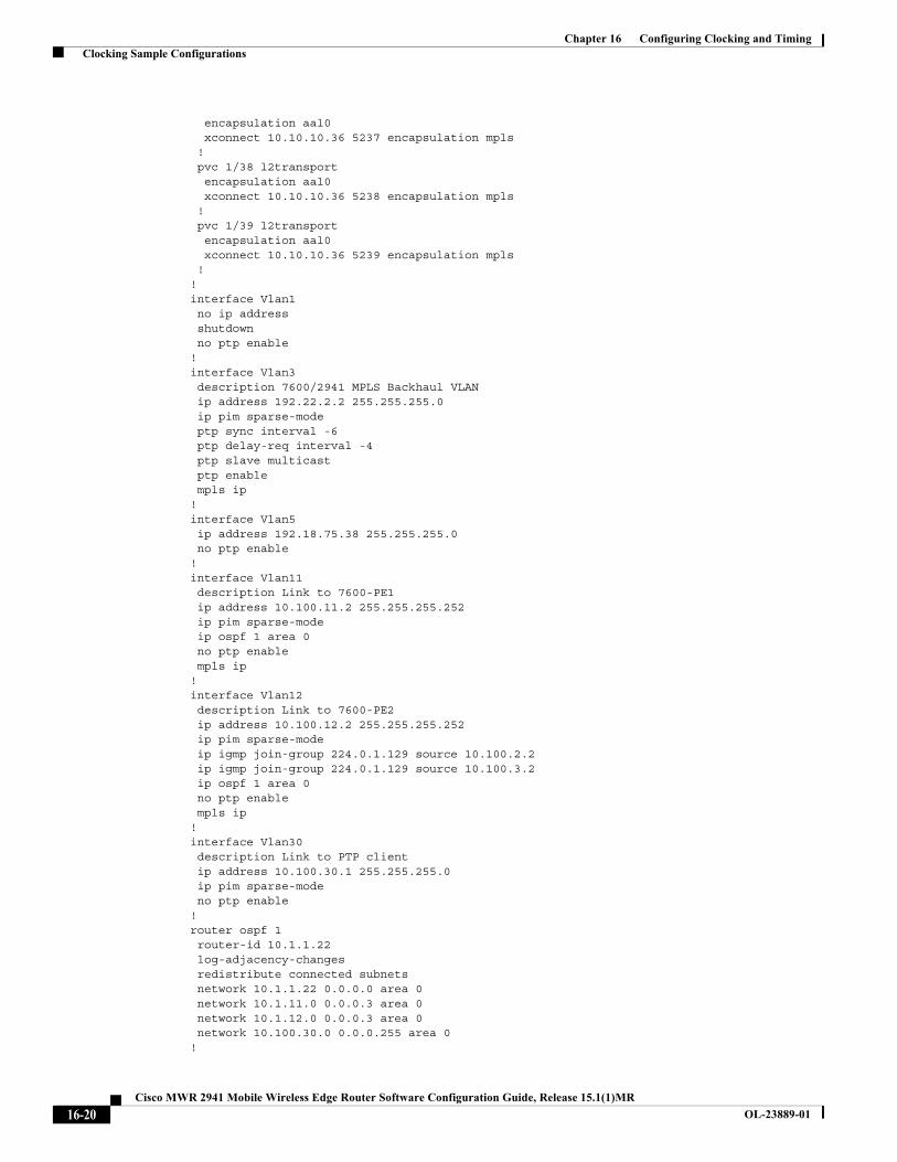
encapsulation aal0 xconnect 10.10.10.36 5237 encapsulation mpls ! pvc 1/38 l2transport encapsulation aal0 xconnect 10.10.10.36 5238 encapsulation mpls ! pvc 1/39 l2transport encapsulation aal0 xconnect 10.10.10.36 5239 encapsulation mpls !!interface Vlan1 no ip address shutdown no ptp enable!interface Vlan3 description 7600/2941 MPLS Backhaul VLAN ip address 192.22.2.2 255.255.255.0 ip pim sparse-mode ptp sync interval -6 ptp delay-req interval -4 ptp slave multicast ptp enable mpls ip!interface Vlan5 ip address 192.18.75.38 255.255.255.0 no ptp enable!interface Vlan11 description Link to 7600-PE1 ip address 10.100.11.2 255.255.255.252 ip pim sparse-mode ip ospf 1 area 0 no ptp enable mpls ip!interface Vlan12 description Link to 7600-PE2 ip address 10.100.12.2 255.255.255.252 ip pim sparse-mode ip igmp join-group 224.0.1.129 source 10.100.2.2 ip igmp join-group 224.0.1.129 source 10.100.3.2 ip ospf 1 area 0 no ptp enable mpls ip!interface Vlan30 description Link to PTP client ip address 10.100.30.1 255.255.255.0 ip pim sparse-mode no ptp enable!router ospf 1 router-id 10.1.1.22 log-adjacency-changes redistribute connected subnets network 10.1.1.22 0.0.0.0 area 0 network 10.1.11.0 0.0.0.3 area 0 network 10.1.12.0 0.0.0.3 area 0 network 10.100.30.0 0.0.0.255 area 0!
16-20Cisco MWR 2941 Mobile Wireless Edge Router Software Configuration Guide, Release 15.1(1)MR
OL-23889-01
Chapter 16 Configuring Clocking and Timing Clocking Sample Configurations
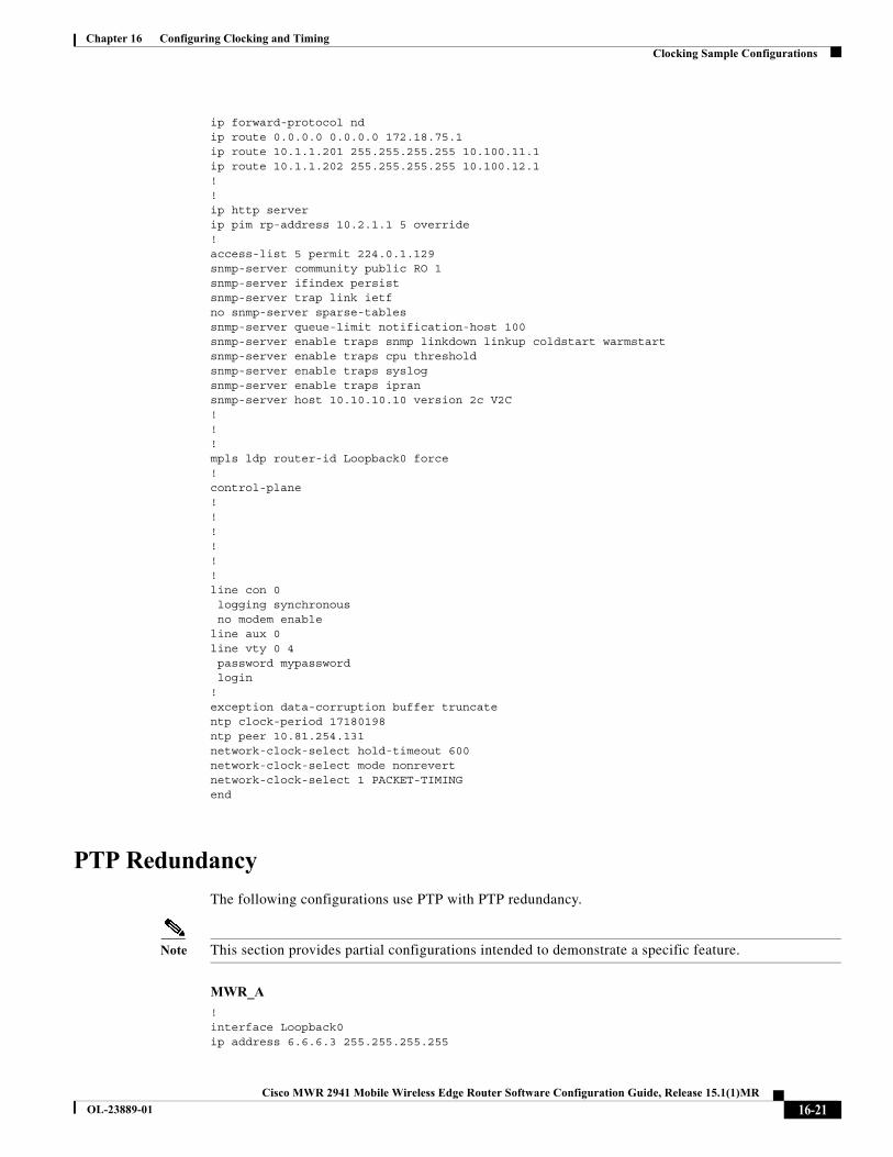
ip forward-protocol ndip route 0.0.0.0 0.0.0.0 172.18.75.1ip route 10.1.1.201 255.255.255.255 10.100.11.1ip route 10.1.1.202 255.255.255.255 10.100.12.1!!ip http serverip pim rp-address 10.2.1.1 5 override!access-list 5 permit 224.0.1.129snmp-server community public RO 1snmp-server ifindex persistsnmp-server trap link ietfno snmp-server sparse-tablessnmp-server queue-limit notification-host 100snmp-server enable traps snmp linkdown linkup coldstart warmstartsnmp-server enable traps cpu thresholdsnmp-server enable traps syslogsnmp-server enable traps ipransnmp-server host 10.10.10.10 version 2c V2C !!!mpls ldp router-id Loopback0 force!control-plane!!!!!!line con 0 logging synchronous no modem enableline aux 0line vty 0 4 password mypassword login!exception data-corruption buffer truncatentp clock-period 17180198ntp peer 10.81.254.131network-clock-select hold-timeout 600 network-clock-select mode nonrevertnetwork-clock-select 1 PACKET-TIMINGend
PTP Redundancy
The following configurations use PTP with PTP redundancy.
Note This section provides partial configurations intended to demonstrate a specific feature.
MWR_A
!interface Loopback0ip address 6.6.6.3 255.255.255.255
16-21Cisco MWR 2941 Mobile Wireless Edge Router Software Configuration Guide, Release 15.1(1)MR
OL-23889-01
Chapter 16 Configuring Clocking and Timing Clocking Sample Configurations
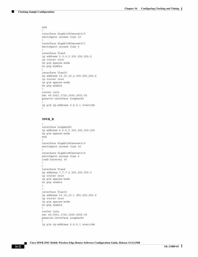
end!interface GigabitEthernet0/0switchport access vlan 10!interface GigabitEthernet0/1switchport access vlan 5!interface Vlan5ip address 5.5.5.2 255.255.255.0ip router isisip pim sparse-modeno ptp enable!interface Vlan10ip address 10.10.10.2 255.255.255.0ip router isis ip pim sparse-modeno ptp enable!router isis net 49.0001.1720.1600.3003.00passive-interface Loopback0!ip pim rp-address 6.6.6.1 override!
MWR_B
!interface Loopback0ip address 6.6.6.2 255.255.255.255ip pim sparse-modeend! interface GigabitEthernet0/0switchport access vlan 10! interface GigabitEthernet0/4switchport access vlan 4load-interval 30!!interface Vlan4ip address 7.7.7.2 255.255.255.0ip router isis ip pim sparse-modeno ptp enable!!interface Vlan10ip address 10.10.10.1 255.255.255.0ip router isis ip pim sparse-modeno ptp enable!router isis net 49.0001.1720.1600.9009.00passive-interface Loopback0!ip pim rp-address 6.6.6.1 override
16-22Cisco MWR 2941 Mobile Wireless Edge Router Software Configuration Guide, Release 15.1(1)MR
OL-23889-01
Chapter 16 Configuring Clocking and Timing Clocking Sample Configurations
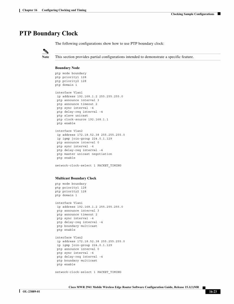
PTP Boundary Clock
The following configurations show how to use PTP boundary clock:
Note This section provides partial configurations intended to demonstrate a specific feature.
Boundary Node
ptp mode boundaryptp priority1 128 ptp priority2 128 ptp domain 1
interface Vlan1 ip address 192.168.1.2 255.255.255.0 ptp announce interval 3 ptp announce timeout 2 ptp sync interval -4 ptp delay-req interval -4 ptp slave unicast ptp clock-source 192.168.1.1 ptp enable
interface Vlan2 ip address 172.18.52.38 255.255.255.0 ip igmp join-group 224.0.1.129 ptp announce interval 0 ptp sync interval -4 ptp delay-req interval -4 ptp master unicast negotiation ptp enable
network-clock-select 1 PACKET_TIMING
Multicast Boundary Clock
ptp mode boundaryptp priority1 128 ptp priority2 128 ptp domain 1
interface Vlan1 ip address 192.168.1.2 255.255.255.0 ptp announce interval 3 ptp announce timeout 2 ptp sync interval -4 ptp delay-req interval -4 ptp boundary multicast ptp enable
interface Vlan2 ip address 172.18.52.38 255.255.255.0 ip igmp join-group 224.0.1.129 ptp announce interval 0 ptp sync interval -4 ptp delay-req interval -4 ptp boundary multicast ptp enable
network-clock-select 1 PACKET_TIMING
16-23Cisco MWR 2941 Mobile Wireless Edge Router Software Configuration Guide, Release 15.1(1)MR
OL-23889-01
Chapter 16 Configuring Clocking and Timing Clocking Sample Configurations
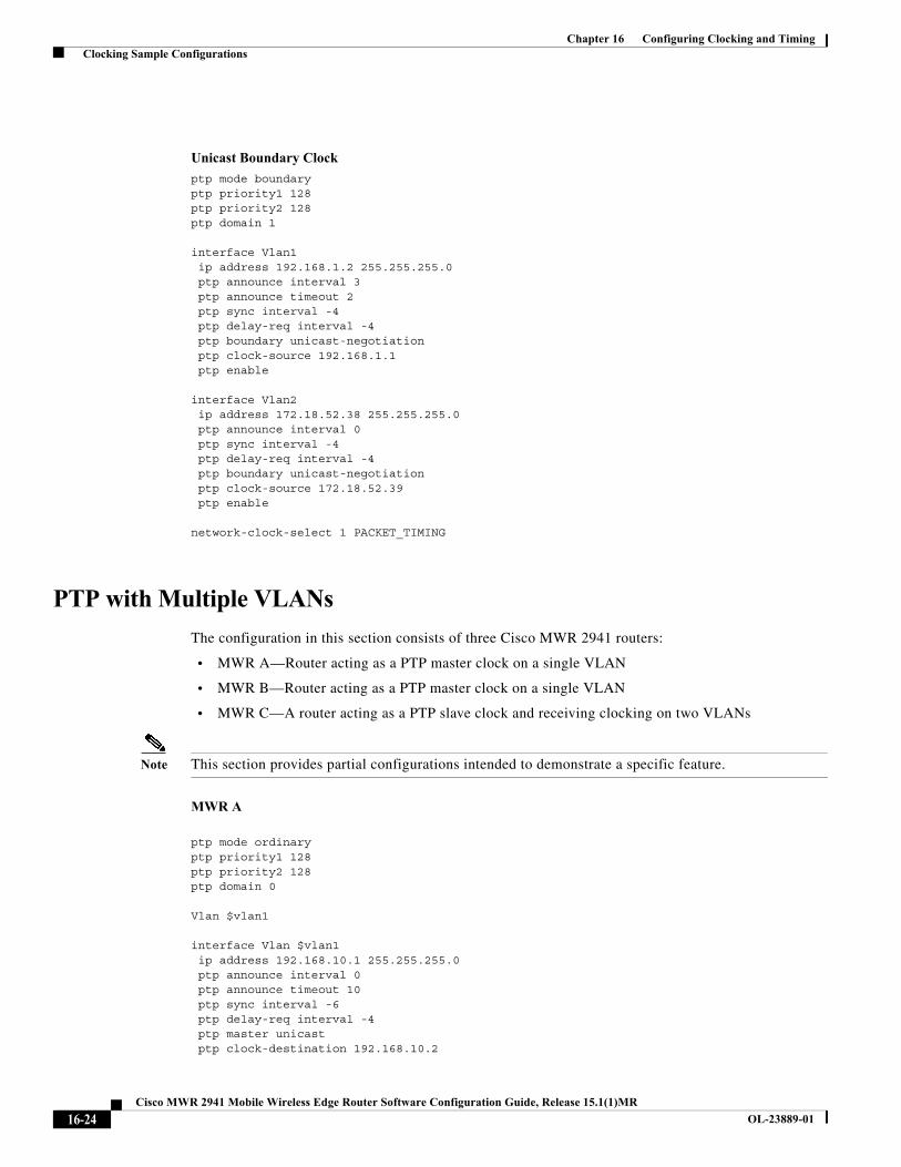
Unicast Boundary Clock
ptp mode boundaryptp priority1 128 ptp priority2 128 ptp domain 1
interface Vlan1 ip address 192.168.1.2 255.255.255.0 ptp announce interval 3 ptp announce timeout 2 ptp sync interval -4 ptp delay-req interval -4 ptp boundary unicast-negotiation ptp clock-source 192.168.1.1 ptp enable
interface Vlan2 ip address 172.18.52.38 255.255.255.0 ptp announce interval 0 ptp sync interval -4 ptp delay-req interval -4 ptp boundary unicast-negotiation ptp clock-source 172.18.52.39 ptp enable
network-clock-select 1 PACKET_TIMING
PTP with Multiple VLANs
The configuration in this section consists of three Cisco MWR 2941 routers:
• MWR A—Router acting as a PTP master clock on a single VLAN
• MWR B—Router acting as a PTP master clock on a single VLAN
• MWR C—A router acting as a PTP slave clock and receiving clocking on two VLANs
Note This section provides partial configurations intended to demonstrate a specific feature.
MWR A
ptp mode ordinaryptp priority1 128ptp priority2 128ptp domain 0
Vlan $vlan1
interface Vlan $vlan1 ip address 192.168.10.1 255.255.255.0 ptp announce interval 0 ptp announce timeout 10 ptp sync interval -6 ptp delay-req interval -4 ptp master unicast ptp clock-destination 192.168.10.2
16-24Cisco MWR 2941 Mobile Wireless Edge Router Software Configuration Guide, Release 15.1(1)MR
OL-23889-01
Chapter 16 Configuring Clocking and Timing Clocking Sample Configurations
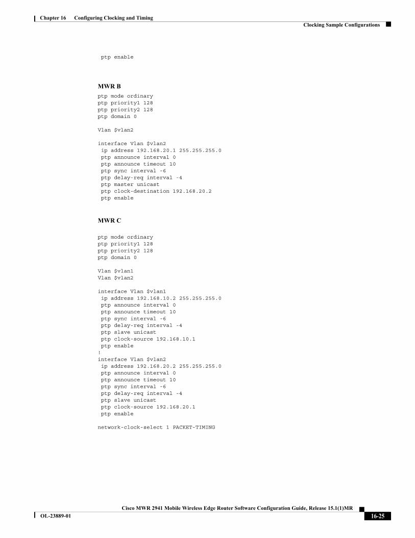
ptp enable
MWR B
ptp mode ordinaryptp priority1 128ptp priority2 128ptp domain 0
Vlan $vlan2
interface Vlan $vlan2 ip address 192.168.20.1 255.255.255.0 ptp announce interval 0 ptp announce timeout 10 ptp sync interval -6 ptp delay-req interval -4 ptp master unicast ptp clock-destination 192.168.20.2 ptp enable
MWR C
ptp mode ordinaryptp priority1 128ptp priority2 128ptp domain 0
Vlan $vlan1Vlan $vlan2
interface Vlan $vlan1 ip address 192.168.10.2 255.255.255.0 ptp announce interval 0 ptp announce timeout 10 ptp sync interval -6 ptp delay-req interval -4 ptp slave unicast ptp clock-source 192.168.10.1 ptp enable!interface Vlan $vlan2 ip address 192.168.20.2 255.255.255.0 ptp announce interval 0 ptp announce timeout 10 ptp sync interval -6 ptp delay-req interval -4 ptp slave unicast ptp clock-source 192.168.20.1 ptp enable
network-clock-select 1 PACKET-TIMING
16-25Cisco MWR 2941 Mobile Wireless Edge Router Software Configuration Guide, Release 15.1(1)MR
OL-23889-01
Chapter 16 Configuring Clocking and Timing Clocking Sample Configurations
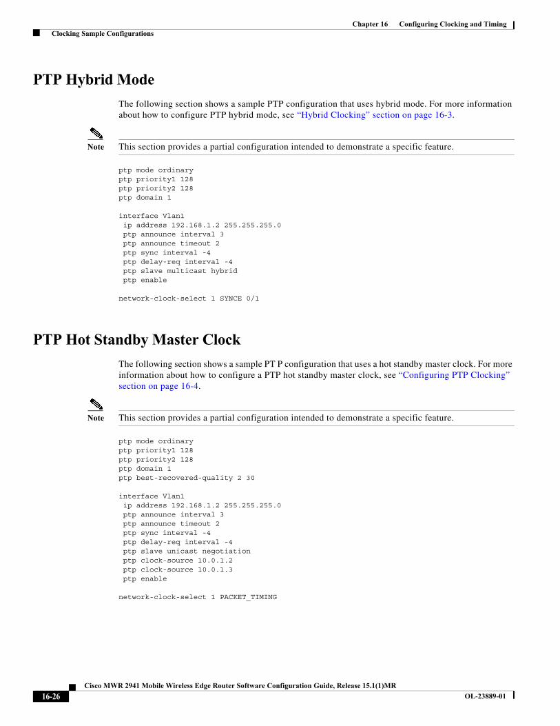
PTP Hybrid Mode
The following section shows a sample PTP configuration that uses hybrid mode. For more information about how to configure PTP hybrid mode, see “Hybrid Clocking” section on page 16-3.
Note This section provides a partial configuration intended to demonstrate a specific feature.
ptp mode ordinary ptp priority1 128ptp priority2 128ptp domain 1
interface Vlan1 ip address 192.168.1.2 255.255.255.0 ptp announce interval 3 ptp announce timeout 2 ptp sync interval -4 ptp delay-req interval -4 ptp slave multicast hybrid ptp enable
network-clock-select 1 SYNCE 0/1
PTP Hot Standby Master Clock
The following section shows a sample PT P configuration that uses a hot standby master clock. For more information about how to configure a PTP hot standby master clock, see “Configuring PTP Clocking” section on page 16-4.
Note This section provides a partial configuration intended to demonstrate a specific feature.
ptp mode ordinary ptp priority1 128 ptp priority2 128 ptp domain 1 ptp best-recovered-quality 2 30
interface Vlan1 ip address 192.168.1.2 255.255.255.0 ptp announce interval 3 ptp announce timeout 2 ptp sync interval -4 ptp delay-req interval -4 ptp slave unicast negotiation ptp clock-source 10.0.1.2 ptp clock-source 10.0.1.3 ptp enable
network-clock-select 1 PACKET_TIMING
16-26Cisco MWR 2941 Mobile Wireless Edge Router Software Configuration Guide, Release 15.1(1)MR
OL-23889-01
Chapter 16 Configuring Clocking and Timing Clocking Sample Configurations
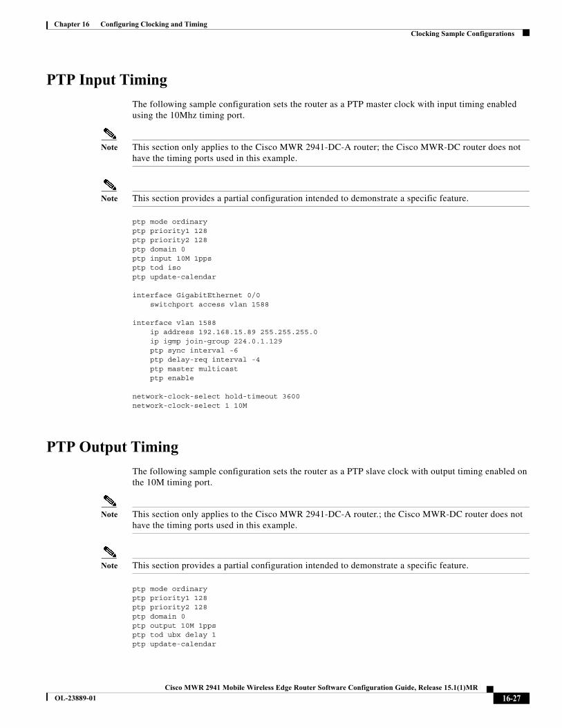
PTP Input Timing
The following sample configuration sets the router as a PTP master clock with input timing enabled using the 10Mhz timing port.
Note This section only applies to the Cisco MWR 2941-DC-A router; the Cisco MWR-DC router does not have the timing ports used in this example.
Note This section provides a partial configuration intended to demonstrate a specific feature.
ptp mode ordinary ptp priority1 128ptp priority2 128 ptp domain 0ptp input 10M 1ppsptp tod isoptp update-calendar
interface GigabitEthernet 0/0 switchport access vlan 1588
interface vlan 1588 ip address 192.168.15.89 255.255.255.0 ip igmp join-group 224.0.1.129 ptp sync interval -6 ptp delay-req interval -4 ptp master multicast ptp enable
network-clock-select hold-timeout 3600network-clock-select 1 10M
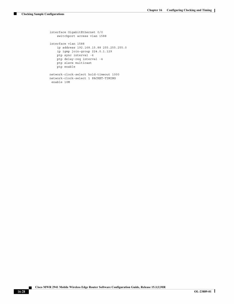
PTP Output Timing
The following sample configuration sets the router as a PTP slave clock with output timing enabled on the 10M timing port.
Note This section only applies to the Cisco MWR 2941-DC-A router.; the Cisco MWR-DC router does not have the timing ports used in this example.
Note This section provides a partial configuration intended to demonstrate a specific feature.
ptp mode ordinary ptp priority1 128ptp priority2 128 ptp domain 0ptp output 10M 1ppsptp tod ubx delay 1ptp update-calendar
16-27Cisco MWR 2941 Mobile Wireless Edge Router Software Configuration Guide, Release 15.1(1)MR
OL-23889-01
Chapter 16 Configuring Clocking and Timing Clocking Sample Configurations
interface GigabitEthernet 0/0 switchport access vlan 1588
interface vlan 1588 ip address 192.168.15.88 255.255.255.0 ip igmp join-group 224.0.1.129 ptp sync interval -6 ptp delay-req interval -4 ptp slave multicast ptp enable
network-clock-select hold-timeout 1000network-clock-select 1 PACKET-TIMING enable 10M
16-28Cisco MWR 2941 Mobile Wireless Edge Router Software Configuration Guide, Release 15.1(1)MR
OL-23889-01