condensing boiler plant (vp) - armstrong fluid...
TRANSCRIPT
Condensing boiler plant (vp) Design Envelope application guide
File No: 9.565Date: november 14, 2014Supersedes: 9.565Date: september 19, 2014
design envelopeapplication guides
performance improvements are among the top priorities of many building professionals today. Whether you are a developer, design consultant, engineer, contractor, facility manager or owner, chances are that you face increasing
demands to not only reduce costs, but also deliver performance improvements. Public awareness on multiple levels – from the individual all the way through to government bodies – has grown to the point that energy conservation, carbon reduction, tenant comfort, and other health and environment-driven practices are key objectives for any prominent, sizeable building project.
To support and sustain this paradigm shift, Armstrong has developed a suite of ad-vanced fluid flow and HVAC offerings that we call ‘Design Envelope solutions’. Design Envelope solutions integrating intelligent demand-based control to deliver optimal performance and the lowest possible cost, both at commissioning and throughout their full operating life.
This document is one of our Design Envelope Application Guides, a set of booklets that discuss a broad range of real-world HVAC scenarios. In each scenario the use of Design Envelope technology can result in tremendous improvements in performance of your HVAC installation (compared to standard industry practice) and ultimately your building - technically, financially, and environmentally.
The intent of this Application Guide is to present HVAC System designers with an alternative to standard practices for design layout, configuration, and design calculations and help you leverage the full potential of Armstrong Design Envelope solutions. Each Application Guide addresses a specific system configuration for HVAC or data center applications. The system configurations cover heating and cooling scenarios, including circuit configurations ranging from all constant flow, to full variable flow and variable speed plant configurations. The Application Guides will present piping arrangements, valving requirements, de-coupler configurations, instrumentation locations, control system options, and the associated impact on first cost and life-cycle costs. The full series of application guides is available for download from Armstrong’s website at www.armstrongfluidtechnology.com
application directory
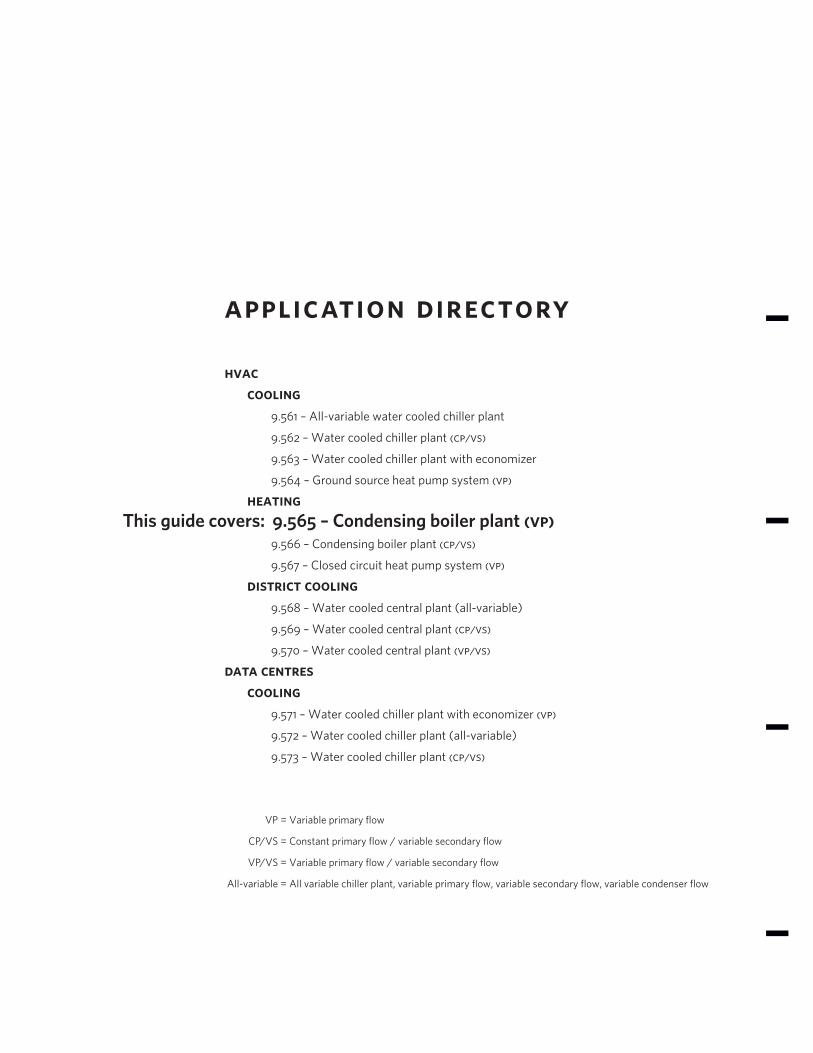
hvac cooling 9.561 – All-variable water cooled chiller plant
9.562 – Water cooled chiller plant (cp/vs)
9.563 – Water cooled chiller plant with economizer
9.564 – Ground source heat pump system (vp)
heating 9.565 – Condensing boiler plant (vp) 9.566 – Condensing boiler plant (cp/vs)
9.567 – Closed circuit heat pump system (vp)
district cooling 9.568 – Water cooled central plant (all-variable)
9.569 – Water cooled central plant (cp/vs)
9.570 – Water cooled central plant (vp/vs)
data centres cooling 9.571 – Water cooled chiller plant with economizer (vp)
9.572 – Water cooled chiller plant (all-variable)
9.573 – Water cooled chiller plant (cp/vs)
VP = Variable primary flow
CP/VS = Constant primary flow / variable secondary flow
VP/VS = Variable primary flow / variable secondary flow
All-variable = All variable chiller plant, variable primary flow, variable secondary flow, variable condenser flow
This guide covers:

design envelope appl ication guide
Condensing boiler plant (vp)
4
The application discussed in this technical paper is for condens-ing boilers with a variable primary design. This would be typical in apartment, schools and other multi-zone facilities.
The plant design that best utilitizes the Design Envelope options includes the Design Envelope 4300 Vertical Inline pumps with integrated controls.
application details
Equipment Condensing boilers •
Use HVAC •
Configuration Var. primary flow •
fig. 2 conventional plant layout.
fig . 1 design envelope plant layout.
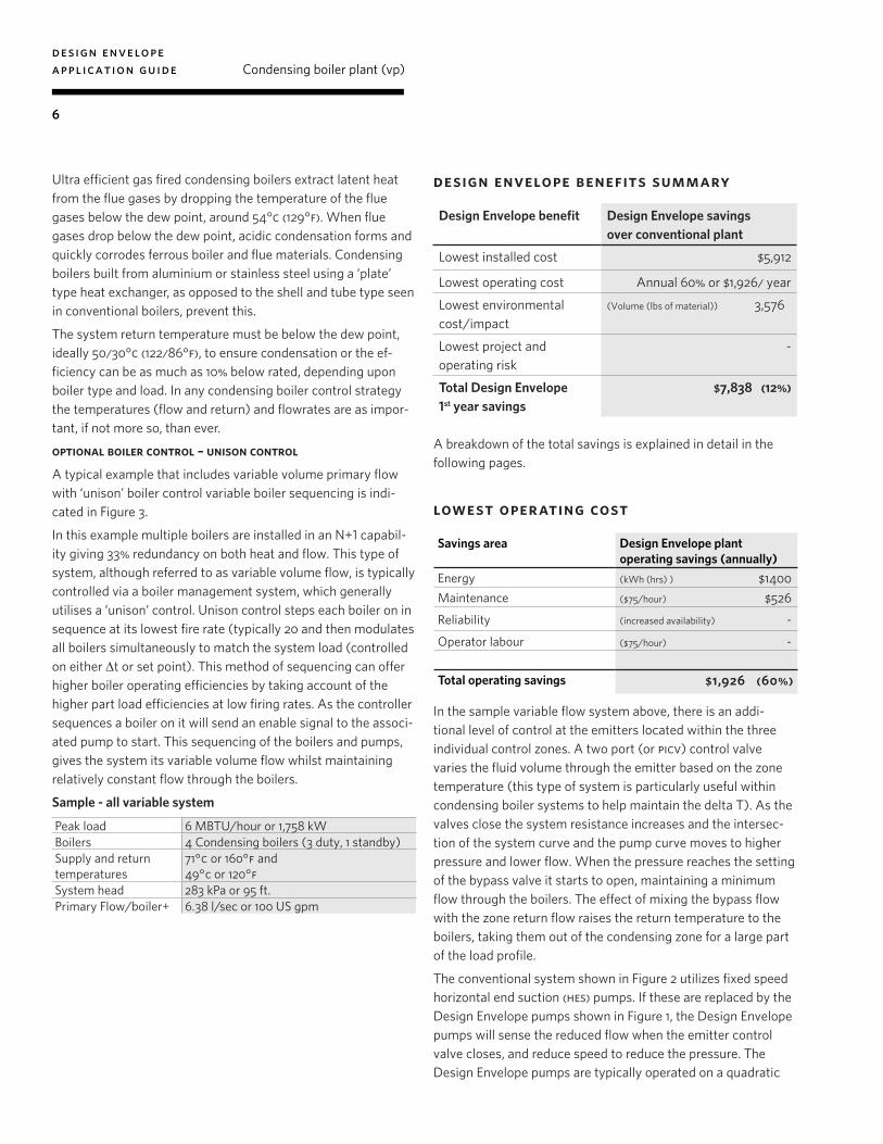
design envelope benefits summary
Design Envelope benefit Design Envelope savings over conventional plant
Lowest installed cost 12%
Lowest operating cost 60%
Lowest environmental cost/impact
3,576 lbs
Lowest project and operating risk
(See table on page 8)
Total Design Envelope 1st year savings
$7,838 (12%)
design envelope appl ication guide
Condensing boiler plant (vp)
5
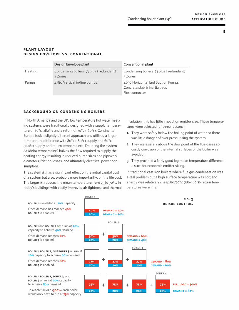
plant layout design envelope vs. conventional
background on condensing boilers
In North America and the UK, low temperature hot water heat-ing systems were traditionally designed with a supply tempera-ture of 80°c (180°f) and a return of 70°c (160°f). Continental Europe took a slightly different approach and utilised a larger temperature difference with 80°c (180°f) supply and 60°c (140°f) supply and return temperatures. Doubling the system ∆t (delta temperature) halves the flow required to supply the heating energy resulting in reduced pump sizes and pipework diameters, friction losses, and ultimately electrical power con-sumption.
The system ∆t has a significant effect on the initial capital cost of a system but also, probably more importantly, on the life cost. The larger ∆t reduces the mean temperature from 75 to 70°c. In today’s buildings with vastly improved air tightness and thermal
Design Envelope plant Conventional plant
Heating Condensing boilers (3 plus 1 redundant) 3 Zones
Condensing boilers (3 plus 1 redundant) 3 Zones
Pumps 4380 Vertical in-line pumps 4030 Horizontal End Suction Pumps Concrete slab & inertia pads Flex connector
insulation, this has little impact on emitter size. These tempera-tures were selected for three reasons:
1. They were safely below the boiling point of water so there was little danger of over pressurising the system.
2. They were safely above the dew point of the flue gases so costly corrosion of the internal surfaces of the boiler was avoided.
3. They provided a fairly good log mean temperature difference (lmtd) for economic emitter sizing.
In traditional cast iron boilers where flue gas condensation was a real problem but a high surface temperature was not; and energy was relatively cheap 80/70°c (180/160°f) return tem-peratures were fine.
20% demand = 20%demand = 40%
demand = 40%demand = 60%
40%
boiler 1
boiler 1 is enabled at 20% capacity.
Once demand has reaches 40% boiler 2 is enabled.
20%30%
20%30%
boiler 2boiler 1 and boiler 2 both run at 20% capacity to acheive 40% demand.
Once demand reaches 60%boiler 3 is enabled.
boiler 1, boiler 2, and boiler 3 all run at 20% capacity to acheive 60% demand.
Once demand reaches 80%boiler 4 is enabled.
+
demand = 60%demand = 80%
20%27%
75% 75% 75% 75%
20%27%+
20%27%
boiler 3
+
boiler 1, boiler 2, boiler 3, and boiler 4 all run at 20% capacity to acheive 80% demand.
To reach full load (300%) each boilerwould only have to run at 75% capacity.
demand = 80%
full load = 300%
20% 20%+
20%+
20%
boiler 4
+
fig. 3 unison control.
design envelope appl ication guide
Condensing boiler plant (vp)
6
design envelope benefits summary
A breakdown of the total savings is explained in detail in the following pages.
lowest operating cost
In the sample variable flow system above, there is an addi-tional level of control at the emitters located within the three individual control zones. A two port (or picv) control valve varies the fluid volume through the emitter based on the zone temperature (this type of system is particularly useful within condensing boiler systems to help maintain the delta T). As the valves close the system resistance increases and the intersec-tion of the system curve and the pump curve moves to higher pressure and lower flow. When the pressure reaches the setting of the bypass valve it starts to open, maintaining a minimum flow through the boilers. The effect of mixing the bypass flow with the zone return flow raises the return temperature to the boilers, taking them out of the condensing zone for a large part of the load profile.
The conventional system shown in Figure 2 utilizes fixed speed horizontal end suction (hes) pumps. If these are replaced by the Design Envelope pumps shown in Figure 1, the Design Envelope pumps will sense the reduced flow when the emitter control valve closes, and reduce speed to reduce the pressure. The Design Envelope pumps are typically operated on a quadratic
Ultra efficient gas fired condensing boilers extract latent heat from the flue gases by dropping the temperature of the flue gases below the dew point, around 54°c (129°f). When flue gases drop below the dew point, acidic condensation forms and quickly corrodes ferrous boiler and flue materials. Condensing boilers built from aluminium or stainless steel using a ‘plate’ type heat exchanger, as opposed to the shell and tube type seen in conventional boilers, prevent this.
The system return temperature must be below the dew point, ideally 50/30°c (122/86°f), to ensure condensation or the ef-ficiency can be as much as 10% below rated, depending upon boiler type and load. In any condensing boiler control strategy the temperatures (flow and return) and flowrates are as impor-tant, if not more so, than ever.
optional boiler control – unison control
A typical example that includes variable volume primary flow with ‘unison’ boiler control variable boiler sequencing is indi-cated in Figure 3.
In this example multiple boilers are installed in an N+1 capabil-ity giving 33% redundancy on both heat and flow. This type of system, although referred to as variable volume flow, is typically controlled via a boiler management system, which generally utilises a ‘unison’ control. Unison control steps each boiler on in sequence at its lowest fire rate (typically 20 and then modulates all boilers simultaneously to match the system load (controlled on either ∆t or set point). This method of sequencing can offer higher boiler operating efficiencies by taking account of the higher part load efficiencies at low firing rates. As the controller sequences a boiler on it will send an enable signal to the associ-ated pump to start. This sequencing of the boilers and pumps, gives the system its variable volume flow whilst maintaining relatively constant flow through the boilers.
Sample - all variable system
Peak load 6 MBTU/hour or 1,758 kWBoilers 4 Condensing boilers (3 duty, 1 standby)Supply and return temperatures
71°c or 160°f and 49°c or 120°f
System head 283 kPa or 95 ft.Primary Flow/boiler+ 6.38 l/sec or 100 US gpm
Design Envelope benefit Design Envelope savings over conventional plant
Lowest installed cost $5,912
Lowest operating cost Annual 60% or $1,926/ year
Lowest environmental cost/impact
(Volume (lbs of material)) 3,576
Lowest project and operating risk
-
Total Design Envelope 1st year savings
$7,838 (12%)
Savings area Design Envelope plant operating savings (annually)
Energy (kWh (hrs) ) $1400 Maintenance ($75/hour) $526 Reliability (increased availability) -
Operator labour ($75/hour) -
Total operating savings $1,926 (60%)

design envelope appl ication guide
Condensing boiler plant (vp)
7
control curve to reduce the pressure as the flow decreases, al-lowing the control valves to stay open further reducing wasted energy. This maintains the head below the bypass valve setting, and maintains the desired delta T so the boiler remains in con-densing mode over almost all of the load profile.
The Design Envelope pump control works with the boiler management system and modulates the flow through the boiler, while the boiler control modulates the flame to maintain the delta T across the boiler. The resulting pump energy savings are $1,412 (60%) against a traditional unison control boiler system with constant speed pumps (equivalent to 14,129 kWh).
lowest installed cost
Installing Armstrong pipeline mounted, vertical inline Design Envelope pumps gives several benefits to the installation, com-missioning and control of the system. The Design Envelope pumps have integrated controls, with an in-rush less than the rated current when initially powered. This compares favourably to the 600%+ in-rush associated with fixed speed motors. In addition the Design Envelope pumps automatically limit pump output, eliminated the need to use large non-overloading mo-tors associated with fixed speed pumps. The pumps eliminate the necessity for concrete plinths and inertia base’s used with the majority of horizontal pumps, eliminating the 3576 lbs of materials from the environmental footprint of the installation.
Design Envelope pumps can be supplied complete with suction guides and a triple duty (Flo-Trex) valve that further enhances the offering and reduces installation time and the physical space requirements. Estimated installation time savings for a project of this size would be in excess of 1 day and require 3-3.5 m2 (36 ft2) less space in the mechanical room than conventional horizontal end suction units, that can be used for other purpos-es and provide easier access for pumps and other mechanical equipment maintenance.
The integrated intelligent drive provided with the Design En-
Savings area Design Envelope plant installed savings
Material & installation ($3,448)Time (labour) ($75/hour) $1,960Power infrastructure (kW connected reduction) -Space (Sq ft ($150/sqft)) $5,400Civil structure -Utility rebates -Commissioning & call backs USD ($75/hour) $2,000Total installed savings $5,912 (10%)
Savings area Design Envelope plant environmental savings
Carbon footprint (energy) (ton ghg [90% ng, 10% hydro]) 10 Construction waste (Volume (lbs of material)) 3,576
lowest environmental cost
velope approach provides further enhanced features that can be leveraged during the commissioning and operation of the system. The controls are programmed with the required flow. Changes can be made at site accommodate variances in head (against design) and flow rate changes (due to design change or boiler selection. Proportional balancing of the boiler circuit is no longer required since the flow is controlled by the sensor-less control in the Design Envelope pump. The minimum boiler flow is set on each individual pump which will speed up the pump when the minimum flow is reached until sufficient pres-sure is reached to open the bypass valve. This would normally only ever operate when one boiler is running at very low load, unless the boiler management system shuts off the boiler. This strategy will maintain a constant flow independent of any pressure fluctuations due to boilers sequencing or variation in the 3 zones whilst minimizing the operation (opening) of the differential by-pass control valve, thus saving energy, stabilizing the operation of the system (in particular the flow through the boilers) and maintaining the return lthw temperature (essential for condensing).
In addition to operating and installation advantages, there are considerable savings in the commissioning process.
Design Envelope pumps can be set for the maximum flow through the boiler. This eliminates the need to balance the flow to the boiler and balance the flow between the various boilers in the system. The Design Envelope pump can be set to maintain a minimum flow rate through the boiler until the pump reaches maximum speed.
Also, for a variable primary system the use of a Design Envelope pump with a maximum operating point (flow and head) will pre-vent the pump pressure from exceeding the operating point as zone valves are closed. This simplifies setting the pressure set-ting on the reverse acting dp valve, and under most situations will allow a significant reduction in the flow capacity of the valve as it will only be required to operate when the load is reduced to below that required when one boiler is operating below the minimum flow rate.
Combined the above should conservatively be expected to save in excess of a full day of on-site commissioning for the flow balancing.
design envelope appl ication guide
Condensing boiler plant (vp)
8
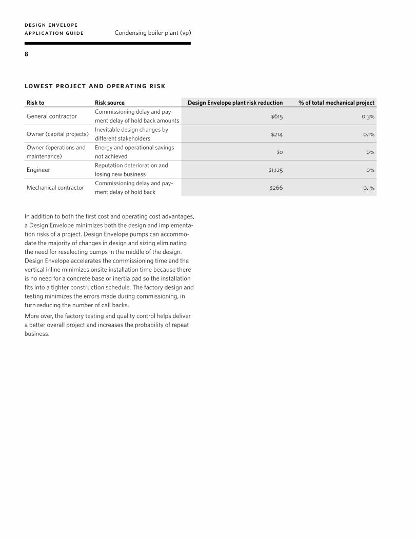
lowest project and operating risk
In addition to both the first cost and operating cost advantages, a Design Envelope minimizes both the design and implementa-tion risks of a project. Design Envelope pumps can accommo-date the majority of changes in design and sizing eliminating the need for reselecting pumps in the middle of the design. Design Envelope accelerates the commissioning time and the vertical inline minimizes onsite installation time because there is no need for a concrete base or inertia pad so the installation fits into a tighter construction schedule. The factory design and testing minimizes the errors made during commissioning, in turn reducing the number of call backs.
More over, the factory testing and quality control helps deliver a better overall project and increases the probability of repeat business.
Risk to Risk source Design Envelope plant risk reduction % of total mechanical project
General contractorCommissioning delay and pay-ment delay of hold back amounts
$615 0.3%
Owner (capital projects)Inevitable design changes by different stakeholders
$214 0.1%
Owner (operations and maintenance)
Energy and operational savings not achieved
$0 0%
EngineerReputation deterioration and losing new business
$1,125 0%
Mechanical contractorCommissioning delay and pay-ment delay of hold back
$266 0.1%
design envelope appl ication guide
Condensing boiler plant (vp)
9
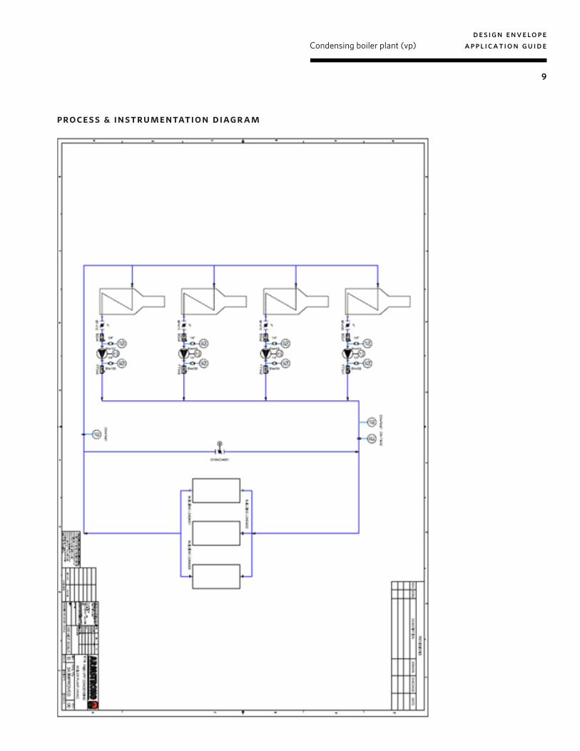
process & instrumentation diagram
tm
b u f f a l o
t o r o n t o
m a n c h e s t e r
b a n g a l o r e
s h a n g h a i
a r m s t r o n g f lu i dt ec h n o lo g y. co m
#59, first floor, 3rd mainmargosa road, malleswarambangalore, india560 003+91 (0) 80 4906 3555
wolverton streetmanchesterunited kingdomm11 2et+44 (0) 8444 145 145
93 east avenuenorth tonawanda, new yorku.s.a.14120-6594+1 716 693 8813
23 bertrand avenuetoronto, ontariocanadam1l 2p3+1 416 755 2291
no. 1619 hu hang road, xi du townshipfeng xian district, shanghaip.r.c.201401+86 21 3756 6696
a r m s t r o n g f lu i d t ec h n o lo g y established 1934
b i r m i n g h a mheywood wharf, mucklow hillhalesowen, west midlandsunited kingdomb62 8dj+44 (0) 8444 145 145