concentrator lab (1)
TRANSCRIPT
7/27/2019 Concentrator Lab (1)
http://slidepdf.com/reader/full/concentrator-lab-1 1/6
ENGN 4525 Solar Concentrator Lab
ENGN 4525 Solar Thermal Technologies
Solar Concentrator Lab
1.1 Introduction
In this laboratory, you will investigate the quality of the concentrator optics a small solartrough concentrator. Dealing with concentrated light is hazardous. You must wearsunglasses and flat heeled shoes during this lab. It is recommended that you take precautionsto protect yourself from sunburn. There are also hot surfaces around the buggy area in thelab to be cautious of. Do not walk in front of the mirror as concentrated light from themirror can cause eye injuries and burns.
1.2 Equipment
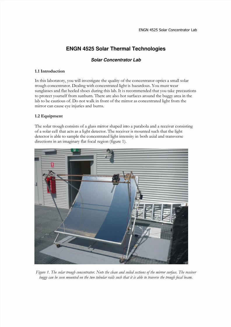
The solar trough consists of a glass mirror shaped into a parabola and a receiver consisting of a solar cell that acts as a light detector. The receiver is mounted such that the lightdetector is able to sample the concentrated light intensity in both axial and transversedirections in an imaginary flat focal region (figure 1).
Figure 1. The solar trough concentrator. Note the clean and soiled sections of the mirror surface. The receiver buggy can be seen mounted on the two tubular rails such that it is able to traverse the trough focal beam.
7/27/2019 Concentrator Lab (1)
http://slidepdf.com/reader/full/concentrator-lab-1 2/6
ENGN 4525 Solar Concentrator Lab
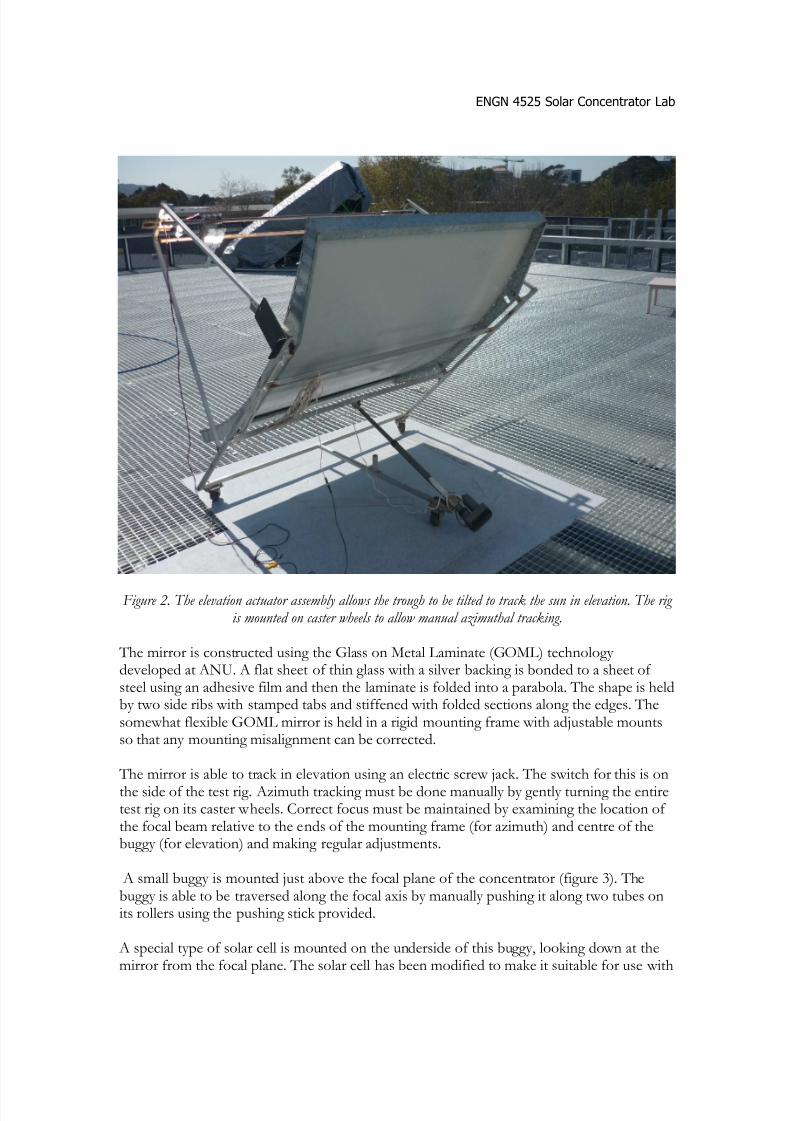
Figure 2. The elevation actuator assembly allows the trough to be tilted to track the sun in elevation. The rig is mounted on caster wheels to allow manual azimuthal tracking.
The mirror is constructed using the Glass on Metal Laminate (GOML) technology developed at ANU. A flat sheet of thin glass with a silver backing is bonded to a sheet of steel using an adhesive film and then the laminate is folded into a parabola. The shape is heldby two side ribs with stamped tabs and stiffened with folded sections along the edges. Thesomewhat flexible GOML mirror is held in a rigid mounting frame with adjustable mountsso that any mounting misalignment can be corrected.
The mirror is able to track in elevation using an electric screw jack. The switch for this is onthe side of the test rig. Azimuth tracking must be done manually by gently turning the entiretest rig on its caster wheels. Correct focus must be maintained by examining the location of the focal beam relative to the ends of the mounting frame (for azimuth) and centre of thebuggy (for elevation) and making regular adjustments.
A small buggy is mounted just above the focal plane of the concentrator (figure 3). Thebuggy is able to be traversed along the focal axis by manually pushing it along two tubes onits rollers using the pushing stick provided.
A special type of solar cell is mounted on the underside of this buggy, looking down at themirror from the focal plane. The solar cell has been modified to make it suitable for use with

7/27/2019 Concentrator Lab (1)
http://slidepdf.com/reader/full/concentrator-lab-1 3/6
ENGN 4525 Solar Concentrator Lab
concentrated light and the assembly is fitted with a heatsink and a fan to prevent the solarcell from overheating. The current produced by the cell is proportional to the light itreceives. Current is measured by a multimeter connected to the cell via a small sense resistor.
In such a way, the solar cell is able to detect variations in the flux intensity along the axis of the trough focal plane.
Figure 3. A close up view of the receiver buggy. The concentrator solar cell is mounted on the underside of the heatsink which is actively cooled by the fan.
The buggy is also fitted with a sliding steel bar. This bar has slots cut through it to allow measuring the light intensity over specific parts of the focus.
Each test needs to be performed reasonably quickly to minimise the effects of changes ininsolation.
2.1 Method
The lab supervisor will assemble the test rig prior to the laboratory and will run through theuse of the equipment.
1. Measure the trough width and focal length. Measure the width of the receiving slot(shielding the solar cell).
7/27/2019 Concentrator Lab (1)
http://slidepdf.com/reader/full/concentrator-lab-1 4/6
ENGN 4525 Solar Concentrator Lab
2. Switch on the buggy cooling fan.
3. Move the trough into focus and allow the solar cell current to stabilise, indicating that asteady state temperature has been reached.
4. Traverse the buggy along the focal beam in 50mm steps using the tape measure andpushing stick provided. Adjust the elevation to keep the beam centred on the target. Thereshould be no shielding of the focal beam for this experiment. Record the solar cell current ateach step.
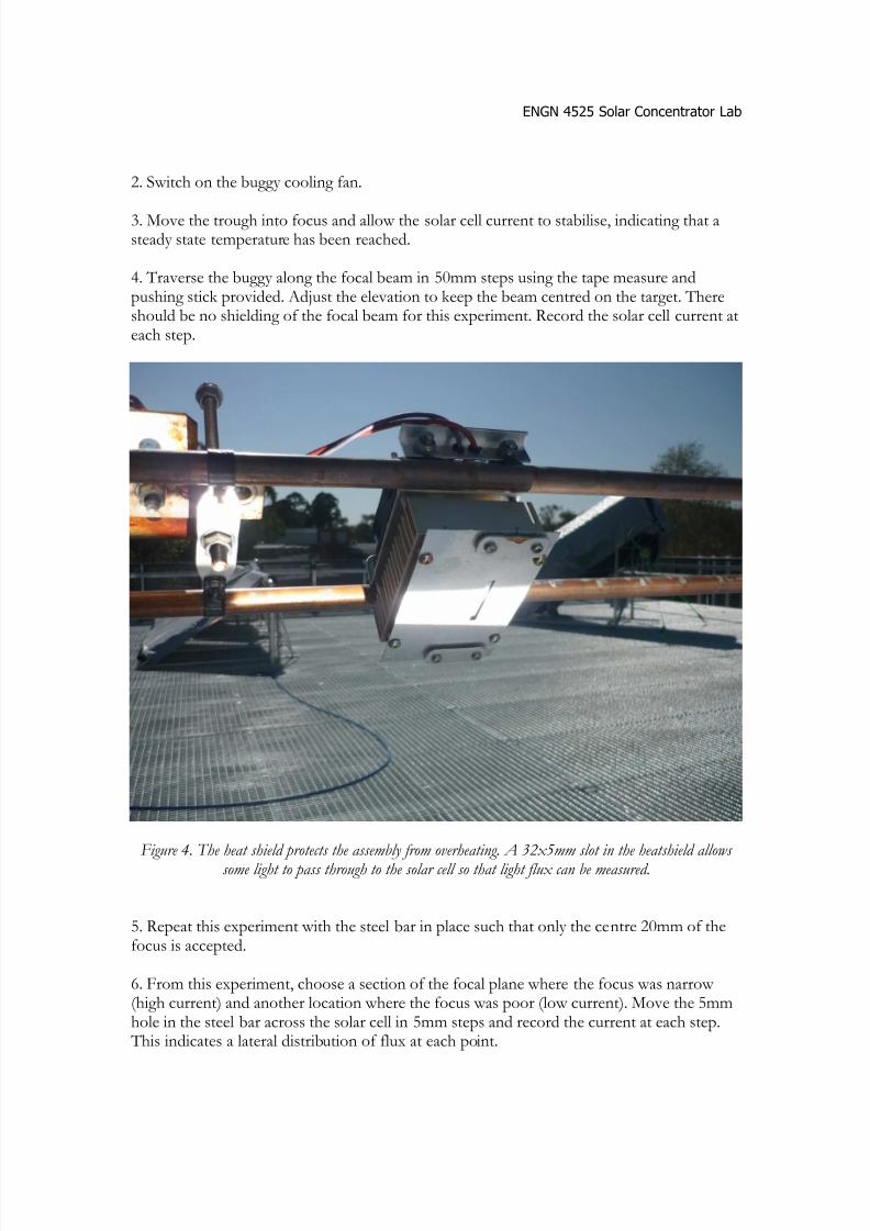
Figure 4. The heat shield protects the assembly from overheating. A 32x5mm slot in the heatshield allows some light to pass through to the solar cell so that light flux can be measured.
5. Repeat this experiment with the steel bar in place such that only the centre 20mm of thefocus is accepted.
6. From this experiment, choose a section of the focal plane where the focus was narrow (high current) and another location where the focus was poor (low current). Move the 5mmhole in the steel bar across the solar cell in 5mm steps and record the current at each step. This indicates a lateral distribution of flux at each point.

7/27/2019 Concentrator Lab (1)
http://slidepdf.com/reader/full/concentrator-lab-1 5/6
ENGN 4525 Solar Concentrator Lab
Figure 5. A steel ruler with a 5mm hole allows light to be sampled across the focal beam in 1mm steps.
7. So far, the trough has been examined with two axis tracking. If the azimuth is fixed suchthat the light has a non-zero incidence angle, then incidence angle effects can be examined. Adjust the azimuth to produce a 30 degree difference in azimuth between the sun andtrough by using the trough shadow as a guide. Repeat the focal traverse experiment frompart 6.
8. Attempt to measure the width of the sun in milli-radians by observing the time it takes forthe focal beam to traverse a fixed line on the receiver.
Results Discussion Questions
1. Calculate the rim angle and geometric concentration ratio.2. If the concentrating optics were perfect, calculate the minimum receiver width
required to capture all of the light from the mirror.3. Plot a graph of the solar cell current along the focal plane. Comment on the
difference between the clean and dirty parts of the mirror. Are there any obviousimperfections in the mirror that lead to the profile detected?
4. Estimate the minimum and maximum optical concentration ratio when the solar cellis unshielded (32 x 5 mm slot) and when the shield (20 x 5mm slot) is in place.
5. Plot graphs of the solar cell current across the focal plane (-16mm<x<16mm) in2.5mm steps, with the steel bar in place (5mm hole).

7/27/2019 Concentrator Lab (1)
http://slidepdf.com/reader/full/concentrator-lab-1 6/6
ENGN 4525 Solar Concentrator Lab
6. Plot the optical concentration ratio across the focal beam in the areas of good andbad focal quality.
7. For a good region of the mirror, determine the percentage loss in light flux when the
elevation tracking errors of -1° to +1° in steps corresponding to 2.5mm of traversing across the focal beam. For your calculations for a receiver of width 15mm.
8. Estimate the angular width of the sun based upon your measurements and explainyour calculation method.
Submitting the lab report
A formal lab report is not required. Answers to each discussion question should be includedin your assignment submission (A text box within an Excel sheet would be acceptable)alongside your experimental results and analysis.
Submit your assignment electronically via Wattle. The due date is Friday of Week13.