complex automatisation system of low power hydroplant.pdf
TRANSCRIPT
Complex Automatisation System of a Low Power Hydroplant
D. Mircescu 1 , A. Astilean2, O. Ghiran3
1 S.C. Hidroserv S.A. Cluj, email: [email protected]
2 Technical University of Cluj Napoca, Faculty of Automation and Computer Science, [email protected] 3 S.C. IPA S.A. Cluj, Cluj-Napoca, Romania, [email protected]
Abstract - Based on the new latest generation programmable automata possibilities, this work presents the main aspects of im-plementing them, to achieve a complex automatisation system of a small power hydro plant (SAC-HmP)
This work presents the SAC-HmP model and the results of the system implemented at C.H.E.M.P. Budac 1 and C.H.E.M.P. Bolovanu (Bistriţa hydrographic basin).
Keywords: programmable automatum (PLC), hydro plant,
monitoring, data acquisition, local control, remote control, hy-droelectric systems, data transmissions, web server.
I. INTRODUCTION
The purpose of this paper is to present the design and the implementation of an automatic control and monitoring system for SAC-HmP hydropower plants based on the last generation InLine PLCs type, which allows the speed and the scalability necessary for managing the automatic processes in a hydro-power plant.
Hydropower is one of the most promising available energy sources in the world [1].
Automatic control systems for hydroelectric units based on electromechanical relay logic have been in general use for many years and, in fact, have been considered standard practice for the industry. Within the past few decades, microprocessor-based controllers have been developed that are suitable for op-eration in a power plant environment. These computer-based systems have been applied for data logging, alarm monitoring, and unit and plant control. Advantages of computer-based con-trol include use of graphical user interfaces, the incorporation of sequence of events, trending, automatic archiving and re-porting into the control system. The incorporation of artificial intelligence and expert system capabilities also enhance the system [2].
PLC’s can be the ideal tool for the automation of a small hy-dro plant and to build a SCADA system on [3].
Furthermore, SAC-HmP architecture allows simple inter-connection with superior levels from hydroelectric systems by the implementation of a SuperWeb server and the possibility of data transfers by OpcServer.
The system is designed for complex automation of a micro-hydropower plant equipped with EOS type generating units (helicoidally turbine, horizontal shaft with S circuit) or FO (ho-rizontal Francis turbine) and asynchrony generators with a no-minal speed rate of 1500 rpm.
Equipment development, factory-based system testing and on-site commissioning were optimized through the creation and use of these cost-effective tools. The tools and structures facilitated a modular solution with comprehensive functionality at an overall low cost [4].
The main requirements for SAC-HmP are: low cost, reliabil-ity and safety in increasing exploitation, local and remote automatic control, ease of use-which allows monitoring and installation exploitation with minimum human intervention. The equipment has to permit self-diagnosis and automatic eli-mination of specific minor faults achieving continuous electric production for the maximum period possible.
II. THE SYSTEM DESIGNING AND ITS FUNCTIONS
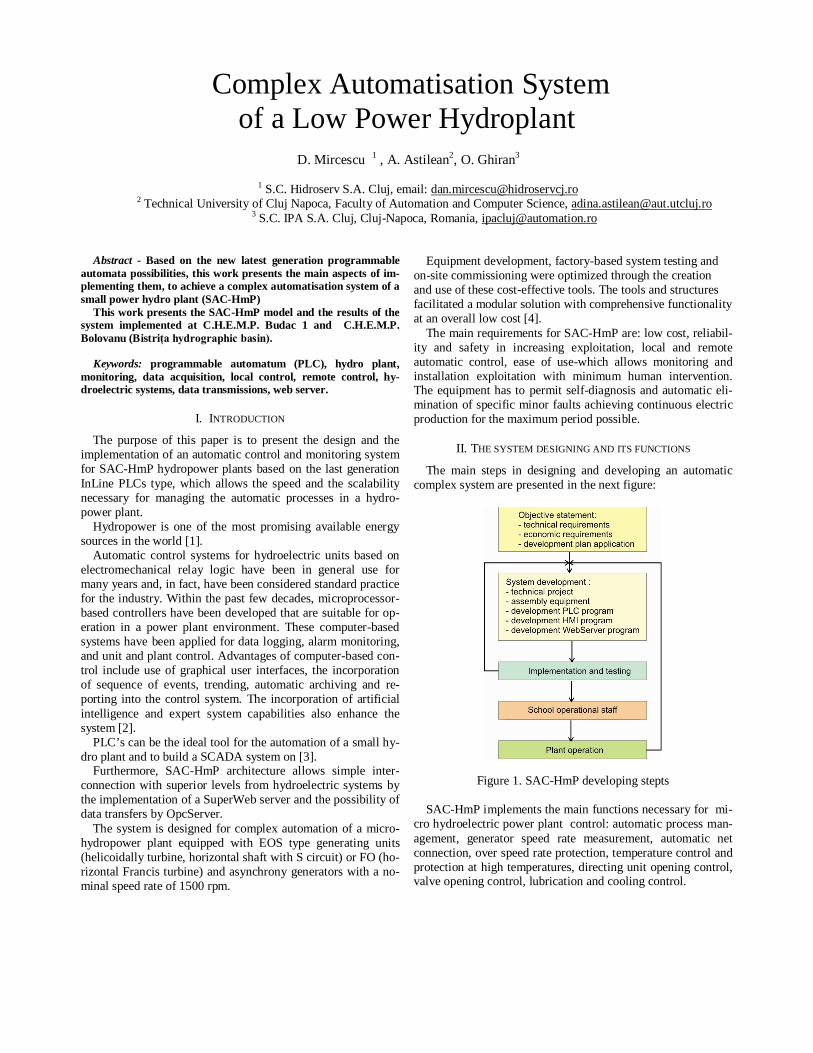
The main steps in designing and developing an automatic complex system are presented in the next figure:
Figure 1. SAC-HmP developing stepts SAC-HmP implements the main functions necessary for mi-
cro hydroelectric power plant control: automatic process man-agement, generator speed rate measurement, automatic net connection, over speed rate protection, temperature control and protection at high temperatures, directing unit opening control, valve opening control, lubrication and cooling control.
At the PLC level the following electrical protections are im-plemented: minimum voltage protection, high voltage protec-tion, asymmetry, phase succession, reverse power; all protec-tions are at the voltage bar level and at the generator level.
The group switch integrated protection implements the fol-lowing functions: the maximum long term current, the maxi-mum short term current, the maximum pulse current.
For local management a HMI panel is used, which allows the exploitation or maintenance personnel to receive all the neces-sary process information. For PLC connection an Ethernet in-dustrial communication net is used, and the data transfer be-tween the devices is achieved by a OpcServer protocol.
Remote control capability is achieved by using the facilities supplied by the integrated PLC web server.
Information collected by the SCADA web server, classified by operational functions is [5]:
- equipment condition;
- data records for variables, transition states and events oc-curring during equipment function; - checks signaling if variable values are in the allowed range; - flow recording at the input and the output of each aggre-gate; - recording of power and energy produced by each aggregate - optimal management of water resources.
For interconnection with intelligent electric measurement monitoring equipment SAC-HmP uses ModbusRTU protocol RS485 communication.
In addition, due to the fact that SAC-HmP is mostly used in isolated locations, without operating personnel, the system im-plements burglary signaling and video surveillance.
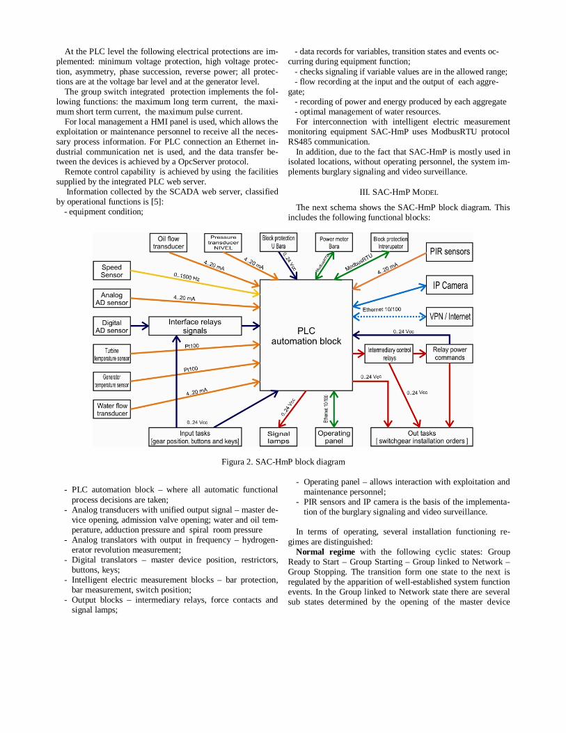
III. SAC-HmP MODEL
The next schema shows the SAC-HmP block diagram. This includes the following functional blocks:
Figura 2. SAC-HmP block diagram
- PLC automation block – where all automatic functional
process decisions are taken; - Analog transducers with unified output signal – master de-
vice opening, admission valve opening; water and oil tem-perature, adduction pressure and spiral room pressure
- Analog translators with output in frequency – hydrogen-erator revolution measurement;
- Digital translators – master device position, restrictors, buttons, keys;
- Intelligent electric measurement blocks – bar protection, bar measurement, switch position;
- Output blocks – intermediary relays, force contacts and signal lamps;
- Operating panel – allows interaction with exploitation and maintenance personnel;
- PIR sensors and IP camera is the basis of the implementa-tion of the burglary signaling and video surveillance.
In terms of operating, several installation functioning re-
gimes are distinguished: Normal regime with the following cyclic states: Group
Ready to Start – Group Starting – Group linked to Network – Group Stopping. The transition form one state to the next is regulated by the apparition of well-established system function events. In the Group linked to Network state there are several sub states determined by the opening of the master device
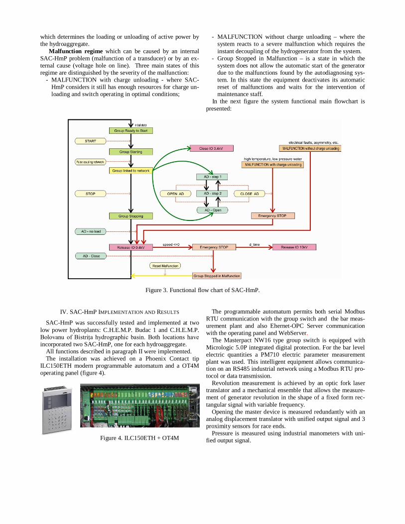
which determines the loading or unloading of active power by the hydroaggregate.
Malfunction regime which can be caused by an internal SAC-HmP problem (malfunction of a transducer) or by an ex-ternal cause (voltage hole on line). Three main states of this regime are distinguished by the severity of the malfunction:
- MALFUNCTION with charge unloading - where SAC-HmP considers it still has enough resources for charge un-loading and switch operating in optimal conditions;
- MALFUNCTION without charge unloading – where the system reacts to a severe malfunction which requires the instant decoupling of the hydrogenerator from the system.
- Group Stopped in Malfunction – is a state in which the system does not allow the automatic start of the generator due to the malfunctions found by the autodiagnosing sys-tem. In this state the equipment deactivates its automatic reset of malfunctions and waits for the intervention of maintenance staff.
In the next figure the system functional main flowchart is presented:
Figure 3. Functional flow chart of SAC-HmP.
IV. SAC-HmP IMPLEMENTATION AND RESULTS
SAC-HmP was successfully tested and implemented at two low power hydroplants: C.H.E.M.P. Budac 1 and C.H.E.M.P. Bolovanu of Bistriţa hydrographic basin. Both locations have incorporated two SAC-HmP, one for each hydroaggregate.
All functions described in paragraph II were implemented. The installation was achieved on a Phoenix Contact tip
ILC150ETH modern programmable automatum and a OT4M operating panel (figure 4).
Figure 4. ILC150ETH + OT4M
The programmable automatum permits both serial Modbus
RTU communication with the group switch and the bar meas-urement plant and also Ehernet-OPC Server communication with the operating panel and WebServer.
The Masterpact NW16 type group switch is equipped with Micrologic 5.0P integrated digital protection. For the bar level electric quantities a PM710 electric parameter measurement plant was used. This intelligent equipment allows communica-tion on an RS485 industrial network using a Modbus RTU pro-tocol or data transmission.
Revolution measurement is achieved by an optic fork laser translator and a mechanical ensemble that allows the measure-ment of generator revolution in the shape of a fixed form rec-tangular signal with variable frequency.
Opening the master device is measured redundantly with an analog displacement translator with unified output signal and 3 proximity sensors for race ends.
Pressure is measured using industrial manometers with uni-fied output signal.
Temperature measurement is achieved using the old measur-ing points with thermo resistances included in the generator structure.
The admission valve position is given by a slope sensor mounted on its arm, and cooling water and lubrication oil con-trol is done by mounting on their flow translator circuits on the calorithmetic principle.
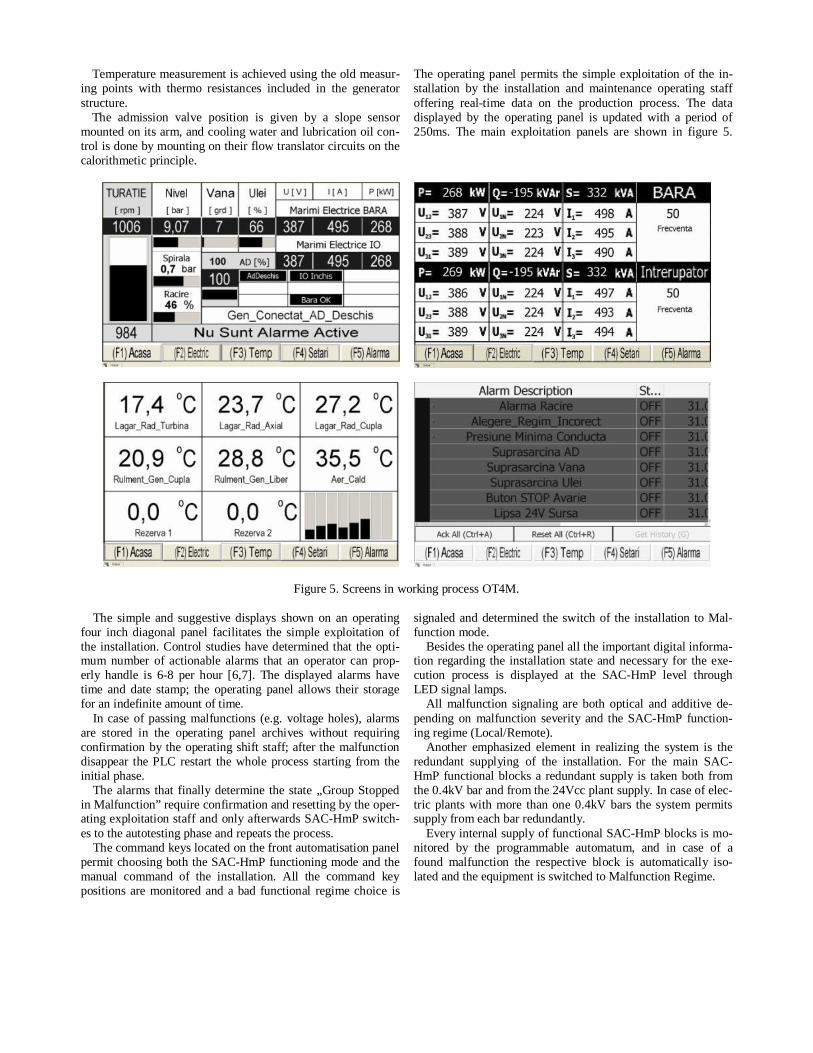
The operating panel permits the simple exploitation of the in-stallation by the installation and maintenance operating staff offering real-time data on the production process. The data displayed by the operating panel is updated with a period of 250ms. The main exploitation panels are shown in figure 5.
Figure 5. Screens in working process OT4M.
The simple and suggestive displays shown on an operating four inch diagonal panel facilitates the simple exploitation of the installation. Control studies have determined that the opti-mum number of actionable alarms that an operator can prop-erly handle is 6-8 per hour [6,7]. The displayed alarms have time and date stamp; the operating panel allows their storage for an indefinite amount of time.
In case of passing malfunctions (e.g. voltage holes), alarms are stored in the operating panel archives without requiring confirmation by the operating shift staff; after the malfunction disappear the PLC restart the whole process starting from the initial phase.
The alarms that finally determine the state „Group Stopped in Malfunction” require confirmation and resetting by the oper-ating exploitation staff and only afterwards SAC-HmP switch-es to the autotesting phase and repeats the process.
The command keys located on the front automatisation panel permit choosing both the SAC-HmP functioning mode and the manual command of the installation. All the command key positions are monitored and a bad functional regime choice is
signaled and determined the switch of the installation to Mal-function mode.
Besides the operating panel all the important digital informa-tion regarding the installation state and necessary for the exe-cution process is displayed at the SAC-HmP level through LED signal lamps.
All malfunction signaling are both optical and additive de-pending on malfunction severity and the SAC-HmP function-ing regime (Local/Remote).
Another emphasized element in realizing the system is the redundant supplying of the installation. For the main SAC-HmP functional blocks a redundant supply is taken both from the 0.4kV bar and from the 24Vcc plant supply. In case of elec-tric plants with more than one 0.4kV bars the system permits supply from each bar redundantly.
Every internal supply of functional SAC-HmP blocks is mo-nitored by the programmable automatum, and in case of a found malfunction the respective block is automatically iso-lated and the equipment is switched to Malfunction Regime.
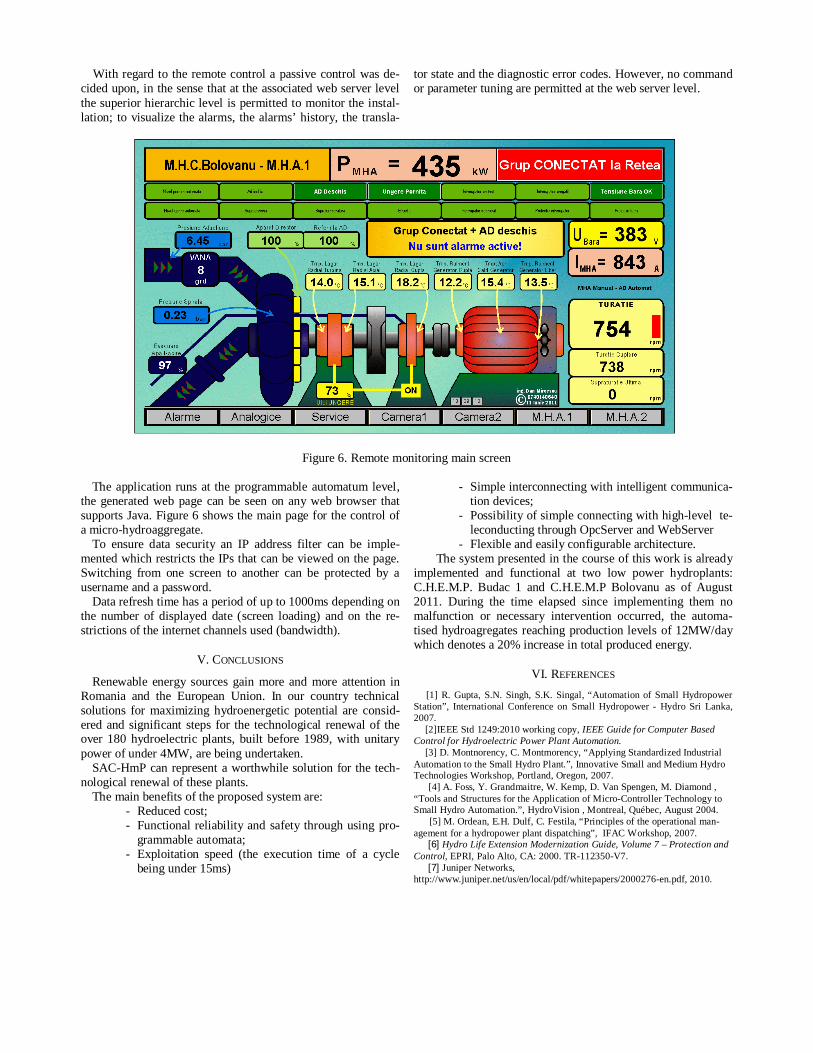
With regard to the remote control a passive control was de-cided upon, in the sense that at the associated web server level the superior hierarchic level is permitted to monitor the instal-lation; to visualize the alarms, the alarms’ history, the transla-
tor state and the diagnostic error codes. However, no command or parameter tuning are permitted at the web server level.
Figure 6. Remote monitoring main screen The application runs at the programmable automatum level,
the generated web page can be seen on any web browser that supports Java. Figure 6 shows the main page for the control of a micro-hydroaggregate.
To ensure data security an IP address filter can be imple-mented which restricts the IPs that can be viewed on the page. Switching from one screen to another can be protected by a username and a password.
Data refresh time has a period of up to 1000ms depending on the number of displayed date (screen loading) and on the re-strictions of the internet channels used (bandwidth).
V. CONCLUSIONS
Renewable energy sources gain more and more attention in Romania and the European Union. In our country technical solutions for maximizing hydroenergetic potential are consid-ered and significant steps for the technological renewal of the over 180 hydroelectric plants, built before 1989, with unitary power of under 4MW, are being undertaken.
SAC-HmP can represent a worthwhile solution for the tech-nological renewal of these plants.
The main benefits of the proposed system are: - Reduced cost; - Functional reliability and safety through using pro-
grammable automata; - Exploitation speed (the execution time of a cycle
being under 15ms)
- Simple interconnecting with intelligent communica-tion devices;
- Possibility of simple connecting with high-level te-leconducting through OpcServer and WebServer
- Flexible and easily configurable architecture. The system presented in the course of this work is already
implemented and functional at two low power hydroplants: C.H.E.M.P. Budac 1 and C.H.E.M.P Bolovanu as of August 2011. During the time elapsed since implementing them no malfunction or necessary intervention occurred, the automa-tised hydroagregates reaching production levels of 12MW/day which denotes a 20% increase in total produced energy.
VI. REFERENCES
[1] R. Gupta, S.N. Singh, S.K. Singal, “Automation of Small Hydropower Station”, International Conference on Small Hydropower - Hydro Sri Lanka, 2007.
[2]IEEE Std 1249:2010 working copy, IEEE Guide for Computer Based Control for Hydroelectric Power Plant Automation.
[3] D. Montnorency, C. Montmorency, “Applying Standardized Industrial Automation to the Small Hydro Plant.”, Innovative Small and Medium Hydro Technologies Workshop, Portland, Oregon, 2007.
[4] A. Foss, Y. Grandmaitre, W. Kemp, D. Van Spengen, M. Diamond , “Tools and Structures for the Application of Micro-Controller Technology to Small Hydro Automation.”, HydroVision , Montreal, Québec, August 2004.
[5] M. Ordean, E.H. Dulf, C. Festila, “Principles of the operational man-agement for a hydropower plant dispatching”, IFAC Workshop, 2007.
[6] Hydro Life Extension Modernization Guide, Volume 7 – Protection and Control, EPRI, Palo Alto, CA: 2000. TR-112350-V7.
[7] Juniper Networks, http://www.juniper.net/us/en/local/pdf/whitepapers/2000276-en.pdf, 2010.