automatisation des rotors d'une station radio amateur. - easy rotor
TRANSCRIPT

Ham Radio Station
Automation :
Your Rotor
March 27th 2013
Richard G. Desaulniers, VE2DX Project Manager, Information Technology
Montreal Port Authority

Station automation history
• Satellite Operations: – Early adopters of station automations;
– Badly needed for tracking of the satellite.
– Operatorless stations.
• Contesting; – Call look up for DUPS.
– DX Cluster look up.
– Multi/Multi station logs.
• Logging software; – Logs.
– Automatic radio control (Frequency, mode, filters, etc…)
– DX Cluster look up.
– Scheduling.
– Automatic Rotor Bearing.
– Digital modes.

Why should I automate my HF or even
VHF station?!?!
• Logger32, HRD, DM780, Logbook, HRD Satellite Tracking and specially HRD Rotator.
• Automatic Radio Interface and control.
• Automatic DX Cluster interface (Log, Station Info, Radio, Rotor, etc…).
• Full integration…

One word… WOW!
• I see rare DX in DX Cluster… – You click on it…
– Log comes up and has ALL the info on the station and the operator…
– Radio has already changed to last known freq and mode of that station.
– Antenna switch selected proper antenna.
– Filters are all setup and ready to go.
– He was operating RTTY and your RTTY window is now up and already decoding…
– And your antenna has started moving to the proper bearing for this station based on is last known QRA

Basic Principals of the rotor
• AC or DC motors turns the antenna or in some cases the tower!
• Rotor Controller supplies power and applies it to the motor in the requested direction.
• A variable resistor installed normally in the motor casing assembly returns a voltage reference, normally 0VDC et ??? VDC, and then again not always.
• A multi-conductor cable between the motor and the controller brings power, controls and feedback to and from the motor.

Basic Principals of the rotor
automation. • Computer via a serial, USB or Ethernet
connection talks to a controller using standardize protocols (Well… Not always completely following the standards!) using an Interface.
• The interface is normally processor controlled, it will convert these commands into controls for the rotor controller via an analogue port.
• The controller powers, controls and gets position feedback from the rotor motor.
• 2 (or 4) direction controls and 1 (or 2) position feedback.

Why not just plug my computer into
my controller?
• Most controllers don’t offer a direct computer connection. And those that do are very expensive.
• Some of the available “computer” ready controllers (mainly Yaesu/Kempro) are not really?
• Most controllers don’t have the intelligence.
• Those Computer ready controllers have TTL inputs and 0-5 VDC, not USB or Serial.
• Most controllers don’t even offer this… But recently we got some options to address even those…

A little bit of History!
• Satellite operations – Urgently needed because;
• Complexity of tracking the Satellite.
• Precision required to track the Satellite.
• Satellite in constantly moving!
– Controls both Azimuth and Elevation.
– Available for many years.
– A common setup is using Yaesu/Kempro G5X00.
– New approach available recently gives you flexibility to use almost ANY « Mismatched! » rotor pairs…
– Many newer interfaces are available a low cost.

• HF – Available for many years…
– Very little interest because of there very high cost until early 2000.
– Very few “computer ready” rotor controllers available.
– Fully integrated logs and contest softwares brought back interest in HF rotor automation.
– HRD, Logger32, WINTEST, N1MM and many other softwares support rotor automation.
– Your best software for complete station and rotor automation if HRD Rotator.
– Cost drastically dropped over the last couple years.
– New options available over the last 2 years really gives you the possibility to automate almost ANY rotor.
A little bit more History!

Rotor Control protocols
• Most common Protocols…
– Easycom I and II (Novacom I).
– DCU-1 and many variations of…
– IdomPress modified DCU-1.
– GS232a and GS232b.
– Some propriotary protocols.

• Easycom I et II – Satellite oriented protocol.
– High precision positioning.
– Even offers CAT and Doppler radio frequency control!
– Rarely used to its full capacity except in some commercial variations.
– Not clearly documented.
– Most available Easycom interfaces are unidirectional (no feedback to the computer!)
– Used in many Ham Satellite interface projects and kits.
Rotor Control protocols

– AZ Azimuth number - 1 decimal place
– EL Elevation number - 1 decimal place
– UP Uplink freq in Hertz
– DN Downlink freq in Hertz
– DM Downlink Mode ascii, eg SSB, FM
– UM Uplink Mode ascii, eg SSB, FM
– DR Downlink Radio number
– UR Uplink Radio number
– ML Move LeftMR Move Right
– MU Move UpMD Move Down
– SA Stop azimuth moving
– SE Stop elevation moving
– AO AOS
– LO LOS
– OP Set output number
– IP Read an input number
– AN Read analogue input number
– ST Set time YY:MM:DD:HH:MM:SS
– VE Request Version
Rotor Control protocols Easycomm II

• DCU-1
– Create by Hy-Gain for there Azimuth rotor
controller called the DCU-1.
– Does not support Elevation control.
– Unidirectionnal (No feedback to the computer)
– Very easy to understand.
– Very Limited!
– Used by many developers…
Rotor Control protocols

• DCU-1
– AP1XXX where XXX is the desired Bearing.
– AM1 Start moving now.
– ; Stop.
– The AI1; is not native to the original DCU1
protocol, this command is used by some
interfaces to get position feedback back to the
computer.
Rotor Control protocols

• DCU-1
– Its actually the DCU protocol and not DCU1?
– The original intent was to control multiple
rotors and to do so change the numeric value
in the commands to select the rotor unit.
– Thus APXYYY and AMX where X would have
been the rotor ID being controlled.
Rotor Control protocols
• IdiomPress
– Based on and compatible with DCU-1.
– Created by IdiomPress for there Azimuth only
rotor interface.
– Does not support elevation.
– Supports AI1 and K/k commands for rotor
position feedback.
– Just like DCU very limited protocol.
Rotor Control protocols

• IdiomPress – AI1; Bearing feedback request (;XXX response where
XXX=bearing)
– AM1 Start moving to bearing defined by previous AP command.
– AP1XXX where XXX is the requested Bearing.
– D turn CCW (Why not L???).
– Gxxx.x to go xxx.x (Combines APXXX and AM1 ).
– K start real time bearing feedback.
– k Stop real time bearing feedback.
– U Turn CW (Why not R???).
– ; Stop.
Rotor Control protocols

• GS232A and GS232B
– Originally created for Yaesu/Kempro
interfaces for there rotors.
– Supports both Azimuth and
Azimuth/Elevation.
– Very powerful.
– More and more used in Ham Kits.
– Supports AZ, AZ/EL and now AZ/AZ!
– Very powerful.
Rotor Control protocols

Protocol GS232a COMMAND LIST 1
R Clockwise Rotation
L Counter Clockwise Rotation
A CW/CCW Rotation Stop
C Antenna Direction Value
M Antenna Direction Setting. MXXX
M Time Interval Direction Setting.
MTTT XXX XXX XXX - - -
(TTT = Step value)
(XXX = Horizontal Angle)
T Start Command in the time interval
direction setting mode.
N Total number of setting angles in “M”
mode and traced number of all datas (setting angles)
X1 Rotation Speed 1 (Horizontal) Low
X2 Rotation Speed 2 (Horizontal) Middle 1
X3 Rotation Speed 3 (Horizontal) Middle 2
X4 Rotation Speed 4 (Horizontal) High
S All Stop
O Offset Calibration
F Full Scale Calibration

Protocol GS232a COMMAND LIST 2
U UP Direction Rotation
D DOWN Direction Rotation
E UP/DOWN Direction Rotation Stop
C2 Antenna Direction Value
W Antenna Direction Setting.
WXXX YYY
W Time Interval Direction Setting.
WTTT XXX YYY XXX YYY ---
(TTT = Step value)
(XXX = Horizontal Angle)
(YYY = Elevation Angle)
T Start Command in the time interval
direction setting mode.
N Total number of setting angle in “W”
mode and traced number of all datas (setting angles)
S All Stop
02 Offset Calibration
F2 Full Scale Calibration
B Elevation Antenna Direction Value

Warning!!!
• Most projets and commercial kits use partial
command sets and some are very limited!
• Know what you need…
• And what they offer….
Rotor Control protocols
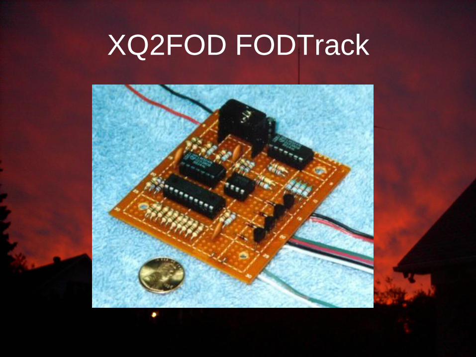
XQ2FOD FODTrack

• Protocol : NA (???)
• Processor : No
• Communication : Unidirectional
• Satellite : Yes
• HF (Azimuth): No
• Simultaneous Control (both axes) : Yes
• Cost : Very Low
• Software Support : Satellite only
• Interface : Parallel
• Calibration : Difficult
• Calibration voltage: 0-5VDC
• Interface: 4 open collector or relays
• Support Overlap No
XQ2FOD FODTrack

Mark WA8SME SAT688
and the ST-1 Clone

Mark WA8SME SAT688
• Protocol : EasyCom I
• Processor : PIC 16F688
• Communication : Unidirectional
• Satellite : Yes
• HF (Azimuth): No
• Simultaneous Control (both axes) : No
• Cost : Very low
• Software Support : Satellite only
• Serial interface : Yes
• USB Interface : Yes
• Calibration : Difficult
• LCD Display: No
• LED : Yes
• Manual control : No
• Calibration Voltage : 0-5VDC
• Interface: 4 open collector
• Overlap Support No

DL7AOT AOTTracker And the ST-3 Clone

• Protocol : EasyCom I and GS232a (Note 1)
• Processor : Pic 16F84
• Communication : Unidirectional
• Satellite : Yes
• HF (Azimuth): No
• Simultaneous Control (Both axes) : No
• Cost : Very Low
• Software : Satellite only
• Serial interface : Yes
• USB Interface: No
• Calibration : Difficult
• LCD Display : Yes
• LED : No
• Manual Control : No (Yes in the ST-3)
• Calibration voltage: 0-5VDC
• Interface: 4 open collector
• Support Overlap Yes
DL7AOT AOTTracker
Note 1 : Very limited command set due to very small memory in the 16F84

G6LVB LVB Tracker
And the ST-2 Clone

• Protocol : GS232a
• Processor : Pic 16F876A
• Communication : Bidirectionnal
• Satellite : Yes
• HF (Azimuth): No
• Simultaneous Control (Both axes) : Yes
• Cost : Very High
• Software : Satellite seulement
• Serial Interface : Yes
• USB Interface : Yes, on LVB original only
• Calibration : Button or commands
• LCD Display: Yes
• LED : No
• Manual Control : Yes
• Calibration Voltage: 0-5VDC
• Interface: 4 open collector
G6LVB LVB Tracker And the ST-2 Clone
The Original LVB does offer an Ethernet option
The Original LVB is used to finance AMSAT-NA et AMSAT-UK

IdiomPress Rotor-Ez and RotorCard

• Protocol : DCU-1 and IdiomPress
• Processor : Unknown??
• Communication : Bidirectionnal
• Satellite : No
• HF (Azimuth): Yes
• Simultaneous Control (Both axes) : NA
• Cost : High
• Software : Log and contest
• Serial Interface : Yes
• USB Interface : No
• Calibration : Commands
• LCD Display: No
• LED : No
• Manual Control : No
• calibration Voltage : 0-5VDC
• Interface: 2 open collector
• Overlap Support Yes
IdiomPress Rotor-Ez and RotorCard

DF9GR ERC
4 variations ERC-1, ERC-3D, ERC-R and ERC-M

• Protocol : GS232a-Az GS232a-El et DCU-1
• Processor : Atmel Mega168-20
• Communication : Bidirectionnal
• Satellite : Yes (but single axis)
• HF (Azimuth): Yes
• Simultaneous Control (Both axes) : NA
• Cost : Low
• Software : Config, log and contest
• Serial Interface : Yes
• USB Interface : No
• Calibration : Simple software based
• LCD Display: No
• LED : No
• Manual Control : No
• calibration Voltage : 0-15VDC on 3 auto calibration ranges
• Interface: 3 Relays (L/R and Aux)
• Overlap Support Yes
ERC-1 Also supports Speed or break control and many other features.
DF9GR ERC-1

• Protocol : GS232A-AZ/EL, GS232A-AZ,
GS232B-AZ/El and GS232A-AZ
• Processor : Atmel Mega168-20
• Communication : Bidirectionnal
• Satellite : Yes
• HF (Azimuth): Yes
• Simultaneous Control (Both axes) : Yes
• Cost : Low
• Software : Config, log and contest
• Serial Interface : Yes
• USB Interface : No
• Calibration : Simple software based
• LCD Display: Yes
• LED : Yes
• Manual Control : Yes
• calibration Voltage : 0-15VDC on 3 auto calibration ranges
• Interface: 5 Relays (L/R/U/D and Aux)
• Overlap Support Yes
ERC-3D Also supports Speed or break control and many other features.
DF9GR ERC-3D (Discontinued)
• Protocol : GS232A-AZ/EL, GS232A-AZ,
GS232B-AZ/El and GS232A-AZ
• Processor : Atmel Mega644P-20
• Communication : Bidirectionnal
• Satellite : Yes
• HF (Azimuth): Yes
• Simultaneous Control (Both axes) : Yes
• Cost : Mid
• Software : Config, log and contest
• Serial Interface : No
• USB Interface : Yes
• Calibration : Simple software based
• LCD Display: Yes
• LED : Yes
• Manual Control : Yes
• calibration Voltage : 0-15VDC on 3 auto calibration ranges
• Interface: 5 Open Collector (L/R/U/D and Aux)
• Overlap Support Yes
ERC-R Also supports Speed or break control and many other features.
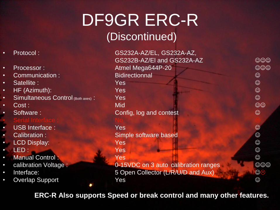
DF9GR ERC-R (Discontinued)

• Protocol : GS232A-AZ/EL, GS232B-AZ/AZ, GS232A-AZ,
GS232B-AZ/EL, GS232B-AZ/AZ, GS232A-AZ DCU and IdiomPress
• Processor : Atmel Mega644P-20 Communication : Bidirectionnal
• Satellite : Yes
• HF (Azimuth): Yes
• Simultaneous Control (Both axes) : Yes
• Cost : Mid
• Software : Config, log and contest
• Serial Interface : Yes
• USB Interface : Yes
• Calibration : Simple software based
• LCD Display: Yes
• LED : Yes
• Manual Control : Yes
• calibration Voltage : 0-15VDC on 3 auto calibration ranges
• Interface: 5 Open Collector or relays (L/R/U/D and Aux)
• Overlap Support Yes
ERC-M Also supports Speed or break control and many other features. (Ethernet Interface, remote relay cards, config save/Restore, etc…)
DF9GR ERC-M

DF9GR ERC ERC-1, ERC-3D, ERC-R and ERC-M

PCB Quality can be an issue
• PCB Quality and assembly varies a lot
among insterface suppliers.
• ERC, ARRL and AMSAT offer high quality
PCBs.
• FoxDelta PCB quality is very poor…
• MDS PCB quality is very high, but the unit
is SMD assembled by hand…

Thanks
de
Richard VE2DX
Special thanks…
CRALL
René DF9GR
Goetz DL7AOT
Laurent F1TE
Howard G6LVB
Simon HB9DRV
Dinesh VU2FD
Mark WA8SME
Manfred XQ2FOD
MARC