cobrimento, fissuração e durabilidade artigo do prof
TRANSCRIPT
Cobrimento, Fissuração e Durabilidade
Artigo do Prof. Yukimasa GOTO - 1971
Formulações para calcular a abertura das fissuras
Pesquisas de Phil Moss FERGUSON - 1968
Prof.. Eduardo C.
S. Thomaz
Notas de aula
1 - Pioneiras experiências feitas por Y.Goto sobre fissuração e aderência.
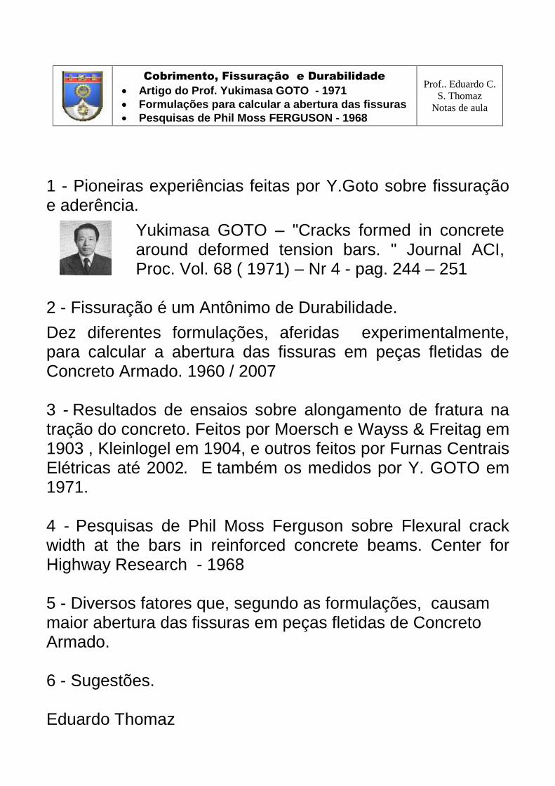
Yukimasa GOTO – "Cracks formed in concrete around deformed tension bars. " Journal ACI, Proc. Vol. 68 ( 1971) – Nr 4 - pag. 244 – 251
2 - Fissuração é um Antônimo de Durabilidade.
Dez diferentes formulações, aferidas experimentalmente, para calcular a abertura das fissuras em peças fletidas de Concreto Armado. 1960 / 2007 3 - Resultados de ensaios sobre alongamento de fratura na tração do concreto. Feitos por Moersch e Wayss & Freitag em 1903 , Kleinlogel em 1904, e outros feitos por Furnas Centrais Elétricas até 2002. E também os medidos por Y. GOTO em 1971. 4 - Pesquisas de Phil Moss Ferguson sobre Flexural crack width at the bars in reinforced concrete beams. Center for Highway Research - 1968 5 - Diversos fatores que, segundo as formulações, causam maior abertura das fissuras em peças fletidas de Concreto Armado. 6 - Sugestões. Eduardo Thomaz

1971 - Cobrimento, Fissuração e Durabilidade
Yukimasa GOTO – Cracks formed in concrete around deformed tension bars. Journal ACI, Proc. Vol. 68 ( 1971) – Nr 4 - pag. 244 – 251
Ensaio de tração em tirantes de concreto armado. Após a fissuração, era feita uma injeção de tinta vermelha nas fissuras. A seguir, o corpo de prova era fendilhado paralelamente à barra.
= entalhe
FISSURAÇÃO OBSERVADA
Y.GOTO - " The cylinder compressive strength and tensile splitting strength of the concrete used
in the experiments were about 4200 and 400 psi (300 kg/cm2 and 28 kg/cm2), respectively."
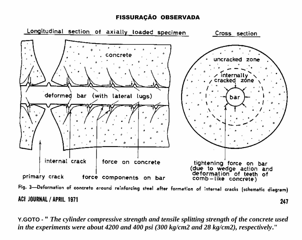
Yukimasa GOTO – Cracks formed in concrete around deformed tension bars
BARRA NERVURADA DE 32 mm
1a
Fissura no concreto com aço = 570 kgf/cm2 , i.e. alongamento = 0,27mm/m
Aumentando a tensão no aço surgem novas fissuras até aço = 3000 kgf/cm2
entalhe entalhe entalhe

Yukimasa GOTO – Cracks formed in concrete around deformed tension bars
BARRA NERVURADA DE 19 mm
1a
Fissura no concreto com aço = 1050 kgf/cm2 , i.e. alongamento = 0,50mm/m
Aumentando a tensão no aço surgem novas fissuras até aço = 3000 kgf/cm2
entalhe entalhe
entalhe
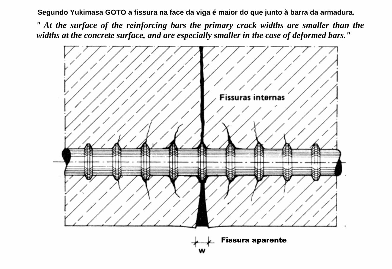
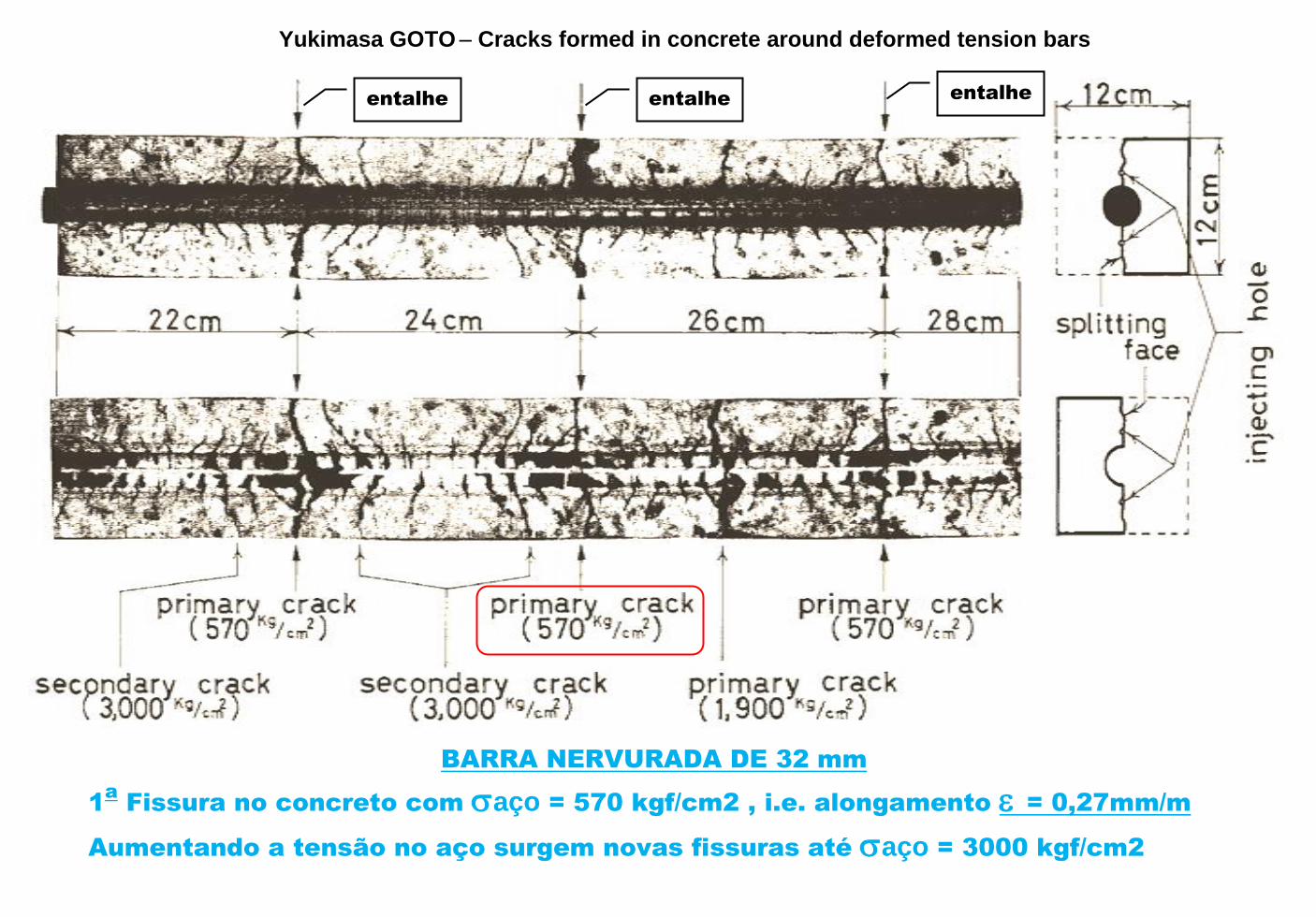
Segundo Yukimasa GOTO a fissura na face da viga é maior do que junto à barra da armadura.
" At the surface of the reinforcing bars the primary crack widths are smaller than the
widths at the concrete surface, and are especially smaller in the case of deformed bars."
Fissura aparente

1960 / 2007
FORMULAÇÕES PARA A ABERTURA DA FISSURA

FORMULAÇÕES PARA A ABERTURA DA FISSURA
a médio = espaçamento médio entre fissuras ; médio = alongamento médio do aço Wmáx = maior abertura de fissura ; Wm = abertura média de fissura ; C = cobrimento ;
S = distância entre as barras ; = diâmetro das barras ;
SII = tensão no aço em serviço. estádio 2. ; fct = resistência à tração do concreto ;
Es = módulo de elasticidade do aço ; = = porcentagem de armadura ( ver na coluna "Observação )

CONTINUAÇÃO

CONTINUAÇÃO
PROFa
. MARIA CASCÃO - 2003 / 2007
2003
/
2007
MARIA CASCÃO 1,7 0,4 a 2 C k3 x k4 x ( / r )
VER ABAIXO

PROFa
MARIA CASCÃO - 2003 / 2007

1903 / 2002
ALONGAMENTO DE RUPTURA À TRAÇÃO DO CONCRETO
ALONGAMENTO DE RUPTURA À TRAÇÃO DO CONCRETO
0
50
100
150
200
250
300
350
0 5 10 15 20 25 30 35 40
ep
sil
on
ru
ptu
ra -
tração
na f
lexão
10
-6
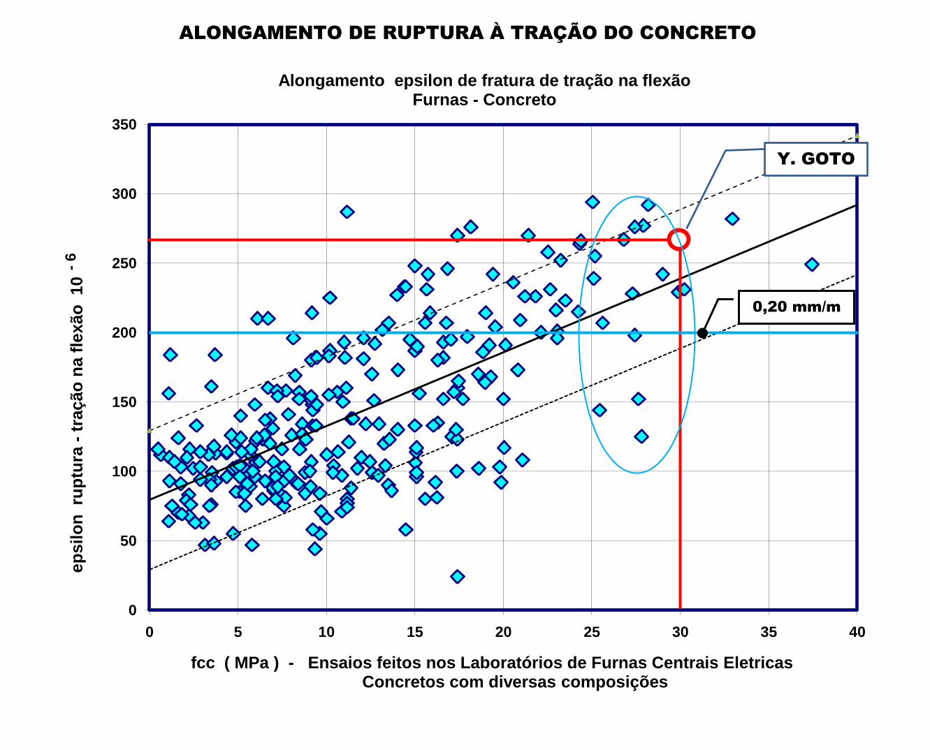
fcc ( MPa ) - Ensaios feitos nos Laboratórios de Furnas Centrais EletricasConcretos com diversas composições
Alongamento epsilon de fratura de tração na flexãoFurnas - Concreto
Y. GOTO
0,20 mm/m
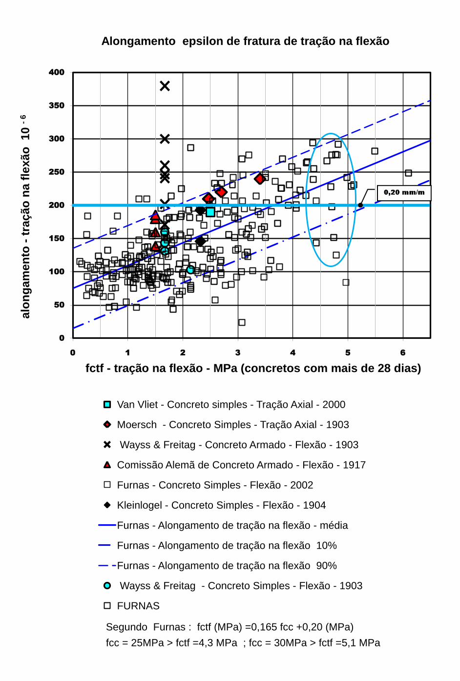
Segundo Furnas : fctf (MPa) =0,165 fcc +0,20 (MPa)
fcc = 25MPa > fctf =4,3 MPa ; fcc = 30MPa > fctf =5,1 MPa
0
50
100
150
200
250
300
350
400
0 1 2 3 4 5 6
alo
ng
am
en
to -
tração
na f
lexão
10 -
6
fctf - tração na flexão - MPa (concretos com mais de 28 dias)
Alongamento epsilon de fratura de tração na flexão
Van Vliet - Concreto simples - Tração Axial - 2000
Moersch - Concreto Simples - Tração Axial - 1903
Wayss & Freitag - Concreto Armado - Flexão - 1903
Comissão Alemã de Concreto Armado - Flexão - 1917
Furnas - Concreto Simples - Flexão - 2002
Kleinlogel - Concreto Simples - Flexão - 1904
Furnas - Alongamento de tração na flexão - média
Furnas - Alongamento de tração na flexão 10%
Furnas - Alongamento de tração na flexão 90%
Wayss & Freitag - Concreto Simples - Flexão - 1903
FURNAS
1968
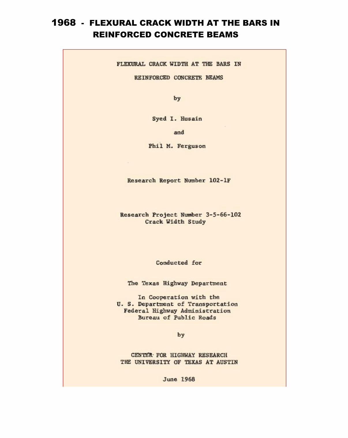
FLEXURAL CRACK WIDTH AT THE BARS IN
REINFORCED CONCRETE BEAMS
Phil Moss Ferguson
THE UNIVERSITY OF TEXAS AT AUSTIN
1968 - FLEXURAL CRACK WIDTH AT THE BARS IN
REINFORCED CONCRETE BEAMS
Phil Moss Ferguson
THE UNIVERSITY OF TEXAS AT AUSTIN
Syed I. Husain
http://behruyan.com/wp-content/uploads/2016/10/crack-1.pdf
https://library.ctr.utexas.edu/digitized/summaries/102-1-f-s.pdf
Research Project Number 3-5-66-102
Crack Width Study
The Texas Highway Department by
CENTER FOR HIGHWAY RESEARCH
THE UNIVERSITY OF TEXAS AT AUSTIN
JUNE 1968
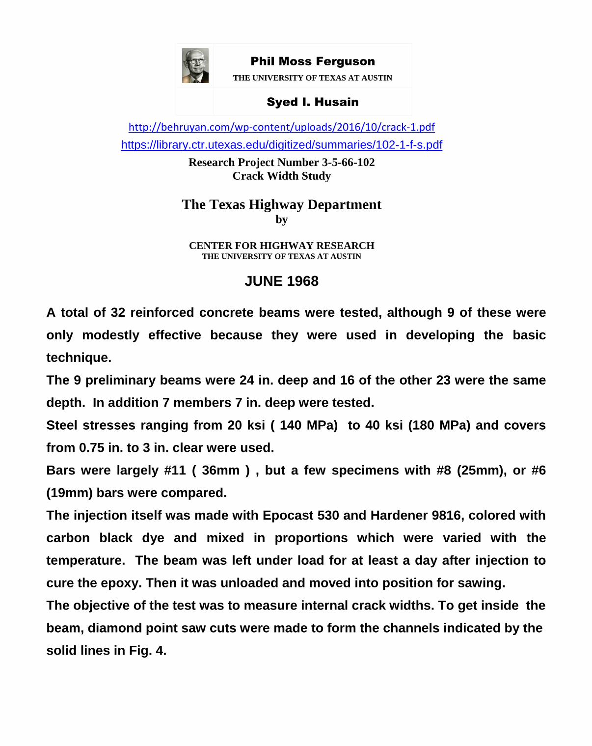
A total of 32 reinforced concrete beams were tested, although 9 of these were
only modestly effective because they were used in developing the basic
technique.
The 9 preliminary beams were 24 in. deep and 16 of the other 23 were the same
depth. In addition 7 members 7 in. deep were tested.
Steel stresses ranging from 20 ksi ( 140 MPa) to 40 ksi (180 MPa) and covers
from 0.75 in. to 3 in. clear were used.
Bars were largely #11 ( 36mm ) , but a few specimens with #8 (25mm), or #6
(19mm) bars were compared.
The injection itself was made with Epocast 530 and Hardener 9816, colored with
carbon black dye and mixed in proportions which were varied with the
temperature. The beam was left under load for at least a day after injection to
cure the epoxy. Then it was unloaded and moved into position for sawing.
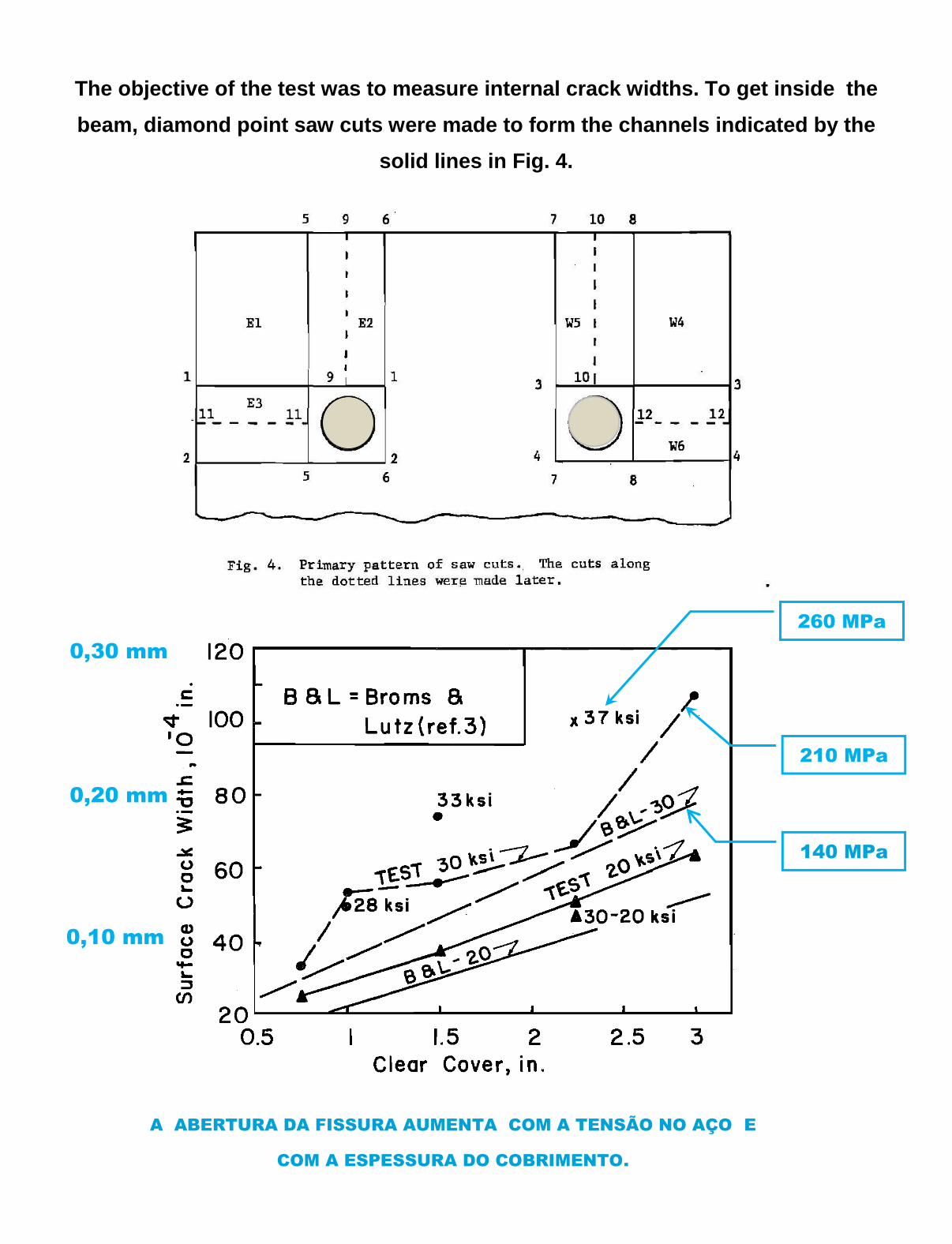
The objective of the test was to measure internal crack widths. To get inside the
beam, diamond point saw cuts were made to form the channels indicated by the
solid lines in Fig. 4.

The objective of the test was to measure internal crack widths. To get inside the
beam, diamond point saw cuts were made to form the channels indicated by the
solid lines in Fig. 4.
A ABERTURA DA FISSURA AUMENTA COM A TENSÃO NO AÇO E
COM A ESPESSURA DO COBRIMENTO.
0,30 mm
260 MPa
0,20 mm
0,10 mm
210 MPa
140 MPa
140 MPa
140 MPa

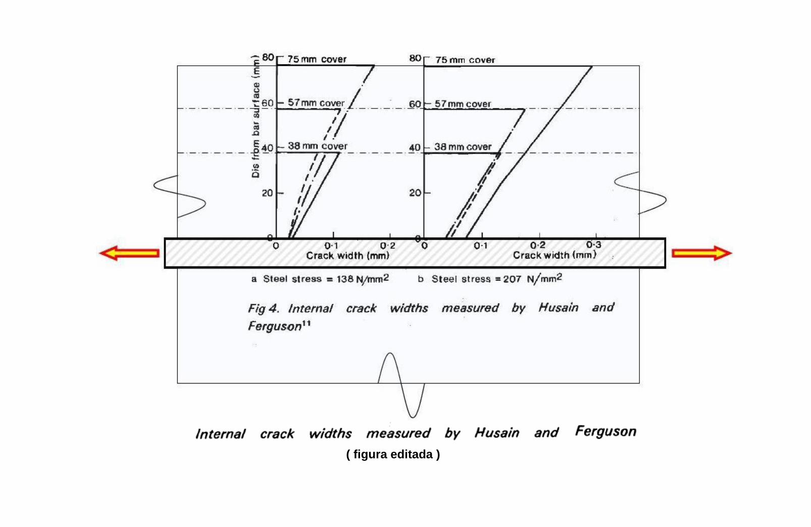
A FISSURA É ESTREITA JUNTO À BARRA DE AÇO E LARGA NA FACE DA VIGA.
( figura editada )
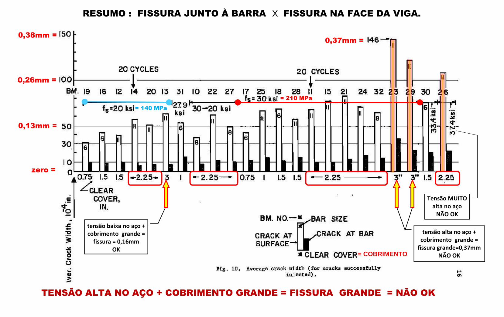
RESUMO : FISSURA JUNTO À BARRA X FISSURA NA FACE DA VIGA.
TENSÃO ALTA NO AÇO + COBRIMENTO GRANDE = FISSURA GRANDE = NÃO OK
= COBRIMENTO
0,26mm =
0,13mm =
= 140 MPa
= 210 MPa
tensão alta no aço + cobrimento grande =
fissura grande=0,37mm NÃO OK
0,37mm =
tensão baixa no aço + cobrimento grande =
fissura = 0,16mm OK
" "
0,38mm =
zero =
Tensão MUITO alta no aço
NÃO OK

Conclusions
A new technique has been developed for measuring the width of cracks within the concrete covering the bars. The tests have clarified the relation between crack width at the bar and at the surface and have given some measure of the width variation within the cover. With this technique the following crack characteristics have been noted. 1. The crack spacing and the crack width at any level vary from average values by at least ± 50%. Average widths are used here for comparisons between cases.
2. Steel stress was the most important variable influencing crack width at the bar. (a) Average crack widths at the bar surface at 20 ksi steel stress range downward from 0.0010 in., the smaller values being associated with thicker bar cover. (b) At 30 ksi the average crack width at the bar is about· 50 percent greater than at 20 ksi, except that at a cover of 3 in. the average jumps suddenly to 0.0029 in. Since no such increase occurs at a cover of 2.25 in. (where the average is only 0.0013 in.), it appears that the extra heavy cover is not actually helpful insofar as cracking is concerned. 3. For other conditions equal, crack width at the beam tension face varied almost linearly with the cover. However, at 30 ksi and 3 in. cover the width was greater than this ratio would suggest. 4. Surface crack width at 30 ksi was (very roughly) 50 percent greater than at 20 ksi, except at at 3 in. cover it was more than doubled. 5. The ratio of crack width at the bar to that at the surface varied from 0.10 to 0.31, being largest in a shallow member with clear cover of 0. 75 in. 6. The crack thickness from bar to surface plotted approximately as a trapezoid, except that shallow members had relatively greater widths at middepth of the cover. A similar nearly linear variation in crack width existed laterally from the bar to the edge of the beam, with slightly smaller crack widths (possibly because nearer the beam neutral axis). 7. Repetitions of load for 20 cycles had no noticeable influence on measured crack dimensions

.
1972
https://library.ctr.utexas.edu/digitized/texasarchive/phase1/112-1f-chr.pdf
The program undertaken spanned four years and involved 82 structural elements. They included 34 normal weight and 6 lightweight loaded beams. Also included were 36 normal weight and 6 lightweight slab specimens. These specimens were subjected to daily spraying with a 3 percent salt solution for various periods of time, ranging up to 34 months. Two views of the testing area where the specimens were sprayed are given in Fig. 1.2.1.
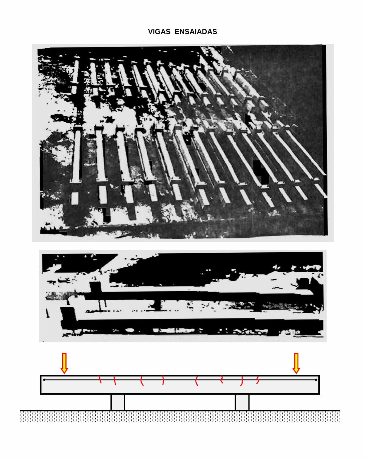
VIGAS ENSAIADAS


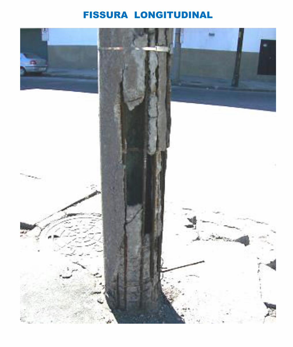
FISSURA LONGITUDINAL
FISSURA LONGITUDINAL
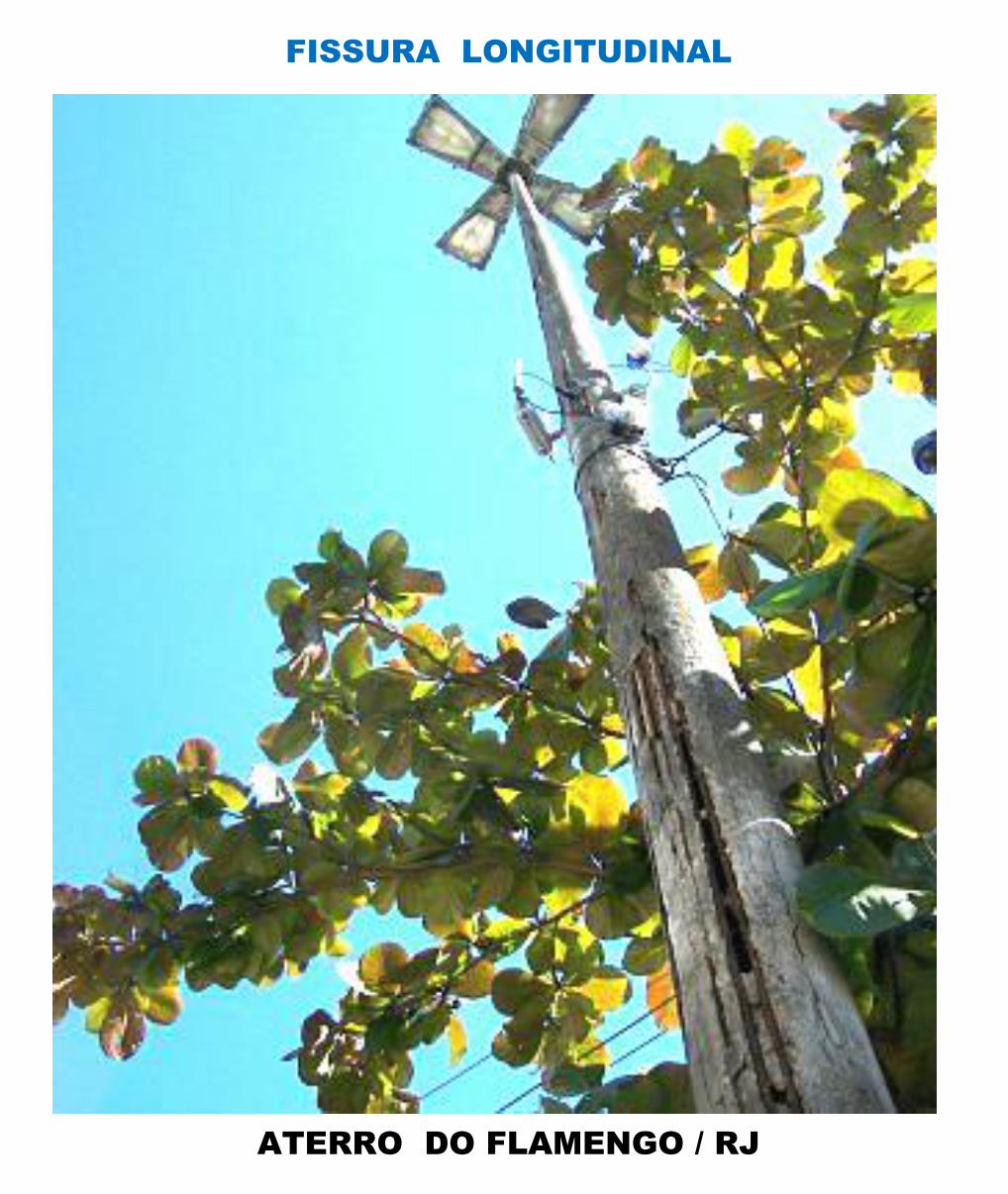
FISSURA LONGITUDINAL
ATERRO DO FLAMENGO / RJ
FISSURA LONGITUDINAL
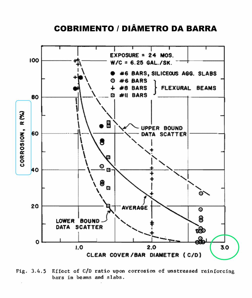
COBRIMENTO / DIÂMETRO DA BARRA
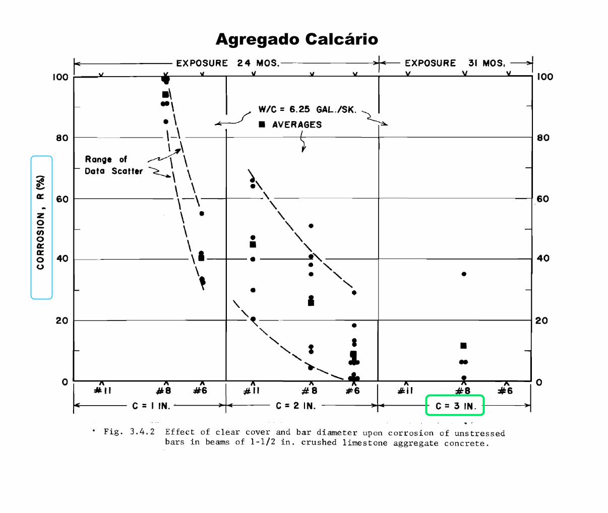
Agregado Calcário
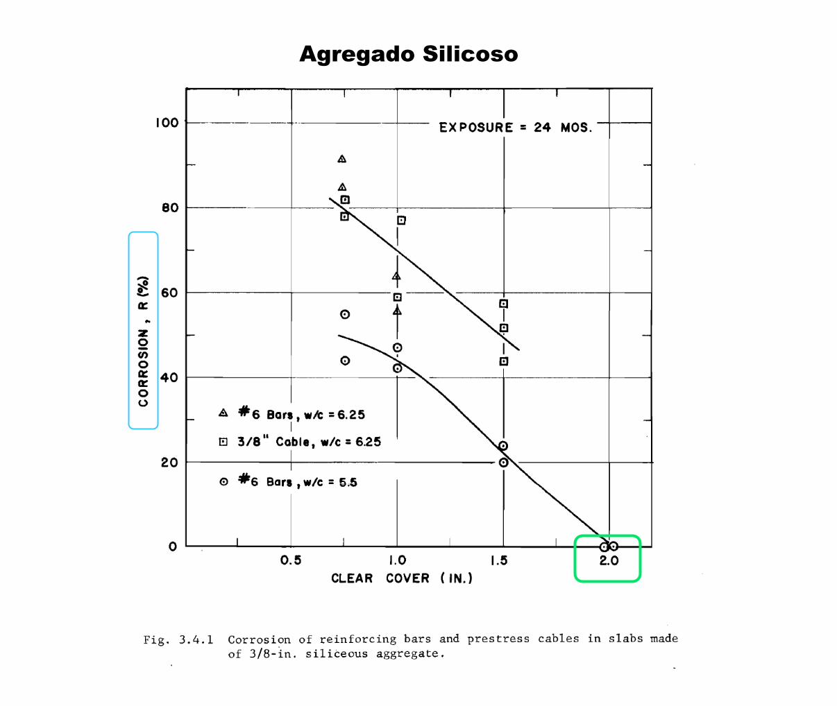
Agregado Silicoso
1978
Andrew W. Beeby

1978 - CORROSION OF REINFORCING STEEL IN CONCRETE
https://trid.trb.org/view/78946
COMENTÁRIOS DE Andrew W. Beeby :
Corrosion damage in practice ( Fotos adicionadas por Eduardo Thomaz, para ilustrar o texto )
When reinforcement rusts, the corrosion products generally occupy considerably more volume than that of the steel destroyed.
The magnitude of this increase in volume varies somewhat from situation to situation, but a value in the region of 2 to 3 times the volume of metal removed would not be unreasonable.
As a result, the corrosion products from quite small reductions in the cross-sectional area of a bar will produce internal stresses sufficient to disrupt the surrounding concrete.
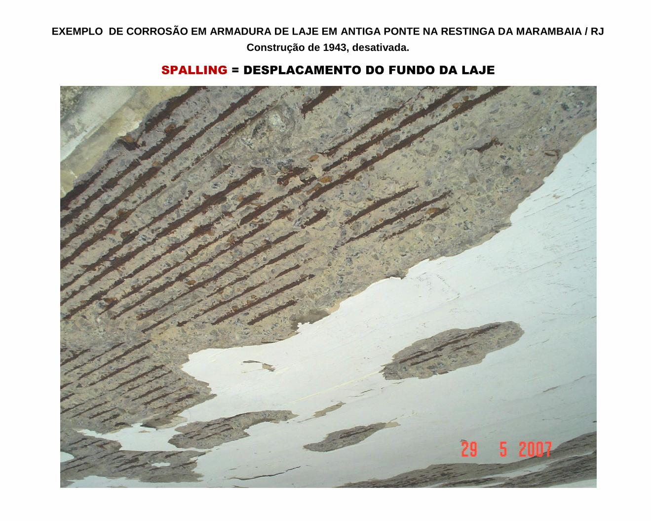
The typical indications of corrosion in reinforced concrete structures are wide cracks along the line of bars, spalled-off corners or substantial spalled areas on slabs. ( VER FOTOS ADIANTE ) In most practical circumstances this spalling occurs well before the reinforcement has become significantly weakened.
Once the cover has been spalled off, rapid corrosion of the exposed steel will take place. ( VER FOTOS ADIANTE ) The indications are that corrosion of exposed bars may occur at about 10 times the rate at which it occurs at cracks, sufficient to cause significant weakening of the bars in a short time relative to the design life of a structure.
The primary objective of design against corrosion is thus design against spalling rather than design against unacceptable loss of reinforcement area.

EXEMPLO DE CORROSÃO EM ARMADURA DE LAJE EM ANTIGA PONTE NA RESTINGA DA MARAMBAIA / RJ
Construção de 1943, desativada.
SPALLING = DESPLACAMENTO DO FUNDO DA LAJE
EXEMPLO DE CORROSÃO EM ARMADURA DE LAJE EM ANTIGA PONTE NA RESTINGA DA MARAMBAIA / RJ
Construção de 1943, desativada.
SPALLING = DESPLACAMENTO DO FUNDO DA LAJE
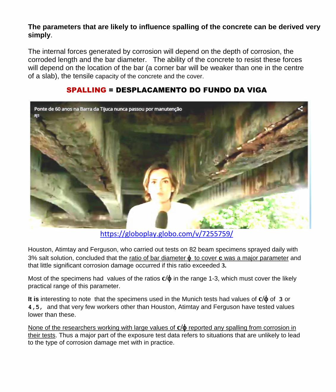
The parameters that are likely to influence spalling of the concrete can be derived very simply. The internal forces generated by corrosion will depend on the depth of corrosion, the corroded length and the bar diameter. The ability of the concrete to resist these forces will depend on the location of the bar (a corner bar will be weaker than one in the centre of a slab), the tensile capacity of the concrete and the cover.
SPALLING = DESPLACAMENTO DO FUNDO DA VIGA
https://globoplay.globo.com/v/7255759/
Houston, Atimtay and Ferguson, who carried out tests on 82 beam specimens sprayed daily with
3% salt solution, concluded that the ratio of bar diameter to cover c was a major parameter and
that little significant corrosion damage occurred if this ratio exceeded 3.
Most of the specimens had values of the ratios c/ in the range 1-3, which must cover the likely
practical range of this parameter.
It is interesting to note that the specimens used in the Munich tests had values of c/ of 3 or
4,5, and that very few workers other than Houston, Atimtay and Ferguson have tested values
lower than these.
None of the researchers working with large values of c/ reported any spalling from corrosion in
their tests. Thus a major part of the exposure test data refers to situations that are unlikely to lead to the type of corrosion damage met with in practice.

Exemplo : Armadura da Viga de uma Ponte na Barra da Tijuca / RJ
SPALLING = DESPLACAMENTO DO FUNDO DA VIGA
https://globoplay.globo.com/v/7627738/
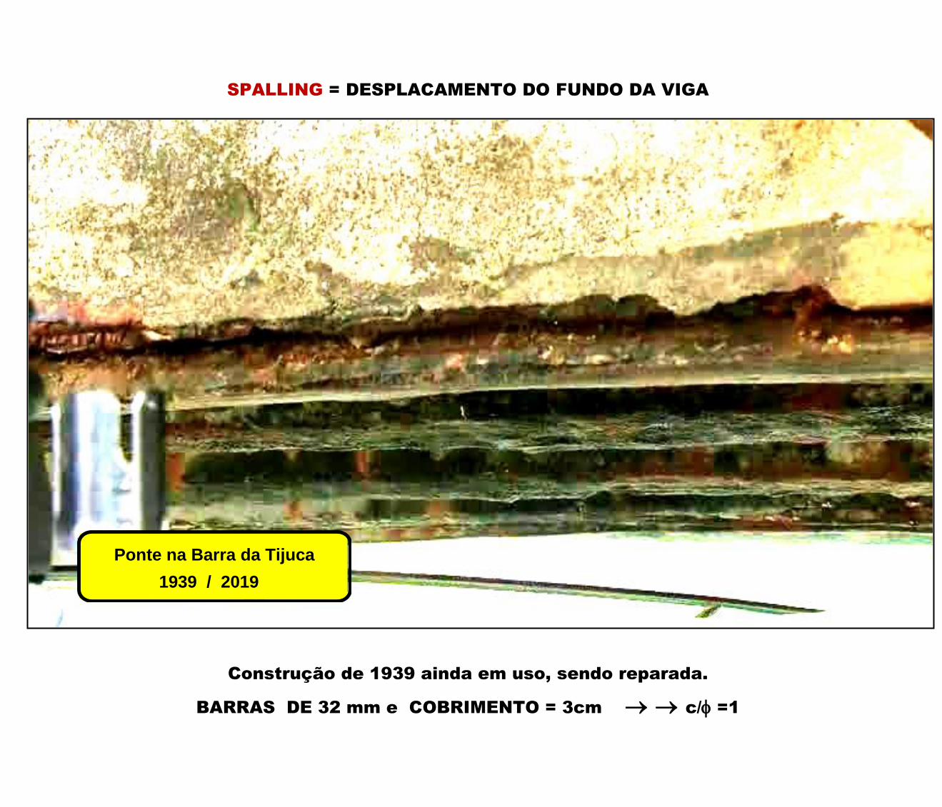
SPALLING = DESPLACAMENTO DO FUNDO DA VIGA
Construção de 1939 ainda em uso, sendo reparada.
BARRAS DE 32 mm e COBRIMENTO = 3cm c/ =1
Ponte na Barra da Tijuca.
............. 1939 / 2019 ......,,,, ..
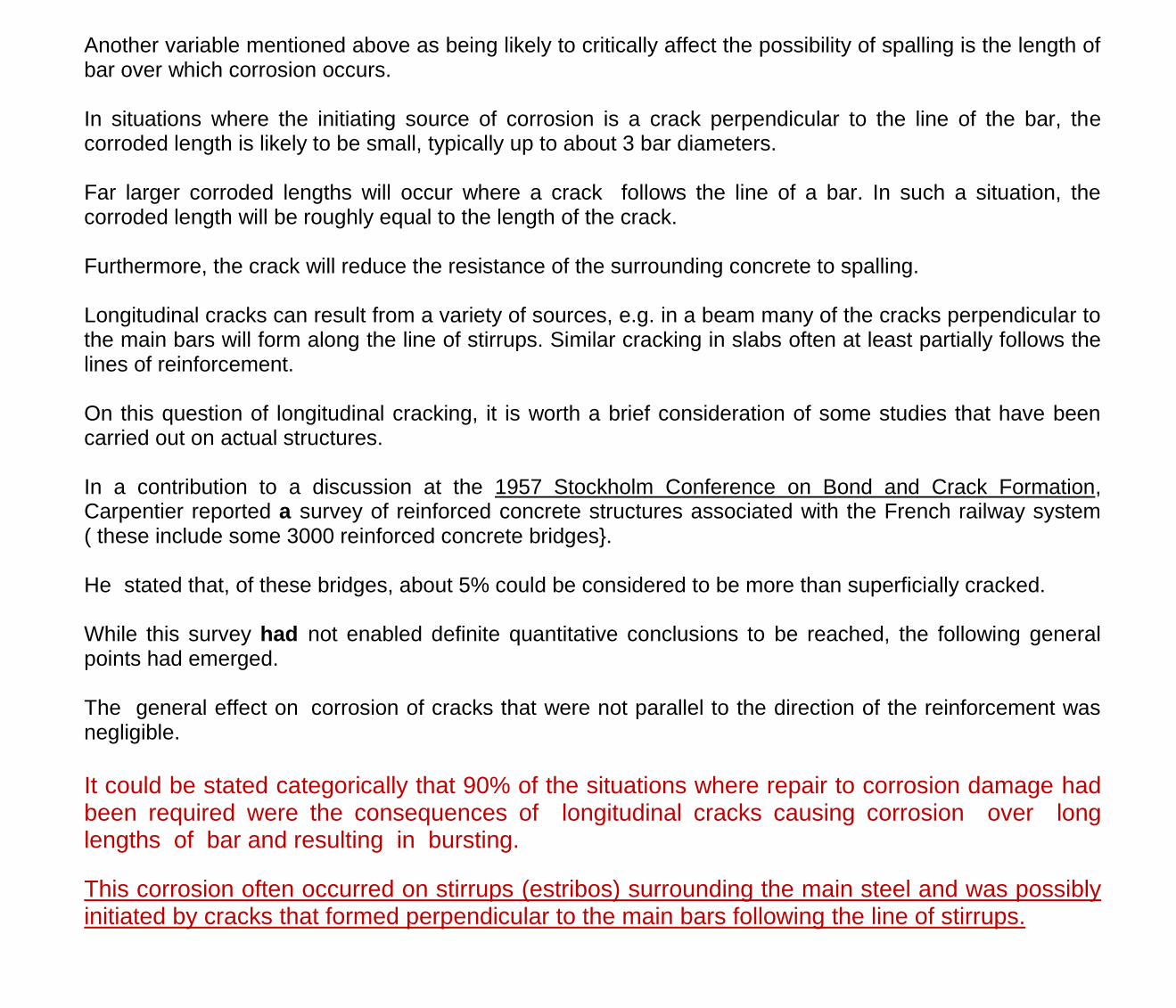
Another variable mentioned above as being likely to critically affect the possibility of spalling is the length of bar over which corrosion occurs. In situations where the initiating source of corrosion is a crack perpendicular to the line of the bar, the corroded length is likely to be small, typically up to about 3 bar diameters. Far larger corroded lengths will occur where a crack follows the line of a bar. In such a situation, the corroded length will be roughly equal to the length of the crack. Furthermore, the crack will reduce the resistance of the surrounding concrete to spalling. Longitudinal cracks can result from a variety of sources, e.g. in a beam many of the cracks perpendicular to the main bars will form along the line of stirrups. Similar cracking in slabs often at least partially follows the lines of reinforcement. On this question of longitudinal cracking, it is worth a brief consideration of some studies that have been carried out on actual structures. In a contribution to a discussion at the 1957 Stockholm Conference on Bond and Crack Formation, Carpentier reported a survey of reinforced concrete structures associated with the French railway system ( these include some 3000 reinforced concrete bridges}. He stated that, of these bridges, about 5% could be considered to be more than superficially cracked. While this survey had not enabled definite quantitative conclusions to be reached, the following general points had emerged. The general effect on corrosion of cracks that were not parallel to the direction of the reinforcement was negligible.
It could be stated categorically that 90% of the situations where repair to corrosion damage had been required were the consequences of longitudinal cracks causing corrosion over long lengths of bar and resulting in bursting.
This corrosion often occurred on stirrups (estribos) surrounding the main steel and was possibly initiated by cracks that formed perpendicular to the main bars following the line of stirrups.

AS DUAS FOTOS ABAIXO MOSTRAM A CORROSÃO NOS ESTRIBOS EM UMA ANTIGA PONTE NA
RESTINGA DA MARAMBAIA NO RIO DE JANEIRO
Construção de 1943, desativada e em recuperação.
BARRAS DE 32 mm e COBRIMENTO = 3cm ---> ---> ---> c/ =1
Similarly, Dechamps et al., who carried out a programme of coring of actual structures to
investigate corrosion at cracks, found that very little corrosion occurred where cracks crossed
bars but the transverse bars ( ESTRIBOS ) were considerably more heavily attacked.
There is a fundamental difficulty associated with the evaluation of data from actual structures; this is that since corrosion causes longitudinal cracking, it is not really possible to tell whether a particular crack caused the corrosion or whether the corrosion caused the crack. Nevertheless it does seem clear that a crack perpendicular to the line of the bar does not constitute a corrosion risk in practice, while the existence of longitudinal crack may.
2010
Crack width variation within the concrete cover of
reinforced concrete members.
ADORJÁN BOROSNYÓI

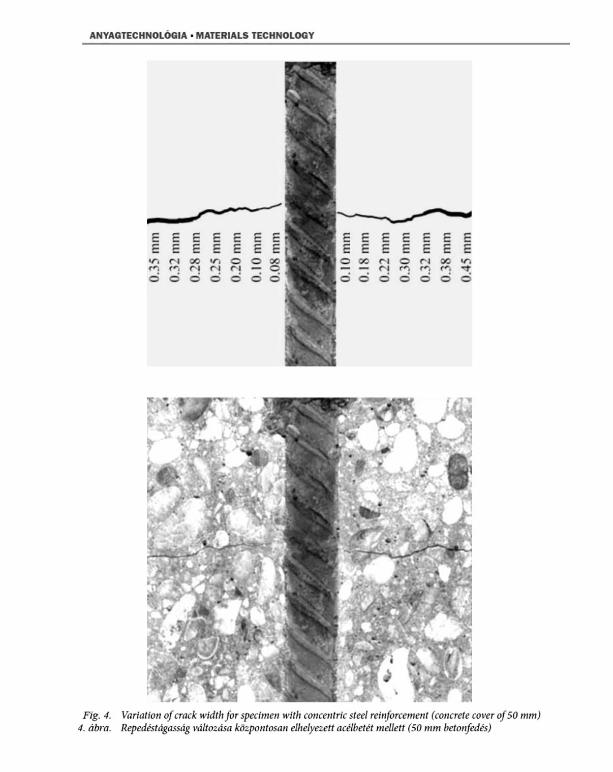
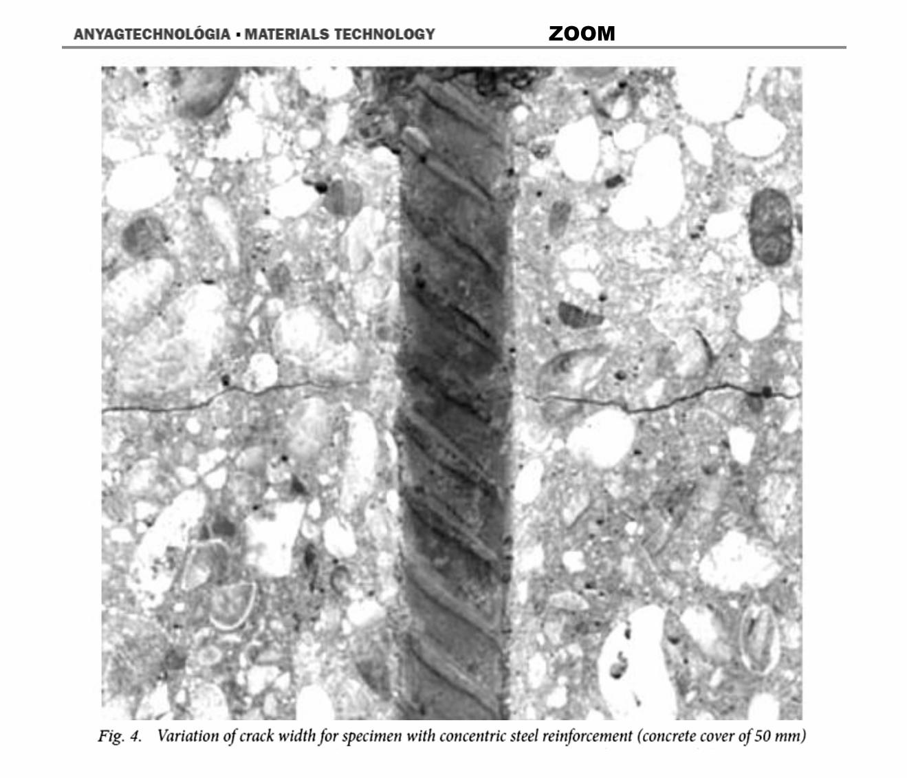
2010 - Crack width variation within the concrete cover of reinforced concrete members
ADORJÁN BOROSNYÓI - BME Dept. of Construction Materials and Engineering Geology -
IVÁN SNÓBLI - BME Dept. of Construction Materials and Engineering Geology - Received: 31.07.2010.
Fig. 1. gives experimental result of Beeby ( 1978 ) indicating considerable differences
between surface crack width and crack width close to the steel reinforcement
- BUDAPEST
ZOOM

építôanyag - 2010/3 - 62. évf. 3. szám = material de construção / 3 2010/3 - Ano 62

2019 - COMENTÁRIOS
EDUARDO THOMAZ

COMENTÁRIOS de Eduardo Thomaz
1 - Para ter uma boa durabilidade, 5cm de um bom concreto, bem lançado, bem vibrado e bem curado, são suficientes, desde que se dimensione a armadura de modo a limitar a abertura de eventuais fissuras a
valores pequenos, por exemplo w0,15mm, 2 - OBS. : Os itens sublinhados nem sempre estão presentes nas obras e projetos 3 - Ter pequenas aberturas de fissuras, significa, em vigas e em lajes, usar tensões baixas nas armaduras, o que sempre acontecia no antigo aço 37CA (= atual CA24) , pois o aço tinha tensões máximas em serviço
de = 1200 kgf/cm2. O elongamento médio do aço era epsilon = =0,6mm/m .
Os ensaios de Yukimasa GOTO mostram o alongamento na fissuração = 0,27mm/m
Y.GOTO - "Internal cracks usually start at a steel stress less than 14 ksi ( 1000 kg/cm2), shortly after
primary cracks are formed. They first develop around lugs (nervuras) near the primary cracks, then
with increase in steel stress or with repetition of load at lugs progressively farther from the primary
cracks."
4 - Hoje, o aço CA50 trabalha, em serviço, com cerca de máx. = 3000 kgf/cm2, embora com melhor
aderência, devido às nervuras, mas o alongamento do aço é bem maior.
O elongamento médio do aço, em serviço, é então epsilon = =1,4mm/m.
5 - O elongamento de ruptura na tração do concreto é cerca de epsilon = 0,20mm /m ( 0,15 mm/m a 0,25mm)
Os ensaios de Yukimasa GOTO mostram alongamento na fissuração epsilon = 0,27mm/m
Ver também : http://aquarius.ime.eb.br/~webde2/prof/ethomaz/fissuracao/flexao_01.pdf Por esse motivo em blocos de fundação recomenda-se usar tensões no aço, em serviço, 175 MPa, o que corresponde a uma abertura de fissura de 0,1mm, segundo as medições feitas por Blévot. Em especial em solos com água contendo substâncias agressivas. Ver : http://aquarius.ime.eb.br/~webde2/prof/ethomaz/bloco_sobre_estacas/bloco_sobre_estacas_02.pdf
COMENTÁRIOS, CONTINUAÇÃO.
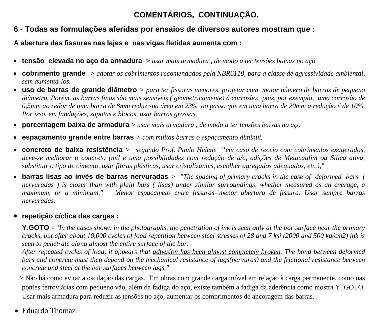
6 - Todas as formulações aferidas por ensaios de diversos autores mostram que :
A abertura das fissuras nas lajes e nas vigas fletidas aumenta com :
tensão elevada no aço da armadura > usar mais armadura , de modo a ter tensões baixas no aço
cobrimento grande > adotar os cobrimentos recomendados pela NBR6118, para a classe de agressividade ambiental,
sem aumentá-los.
uso de barras de grande diâmetro > para ter fissuras menores, projetar com maior número de barras de pequeno
diâmetro. Porém. as barras finas são mais sensíveis ( geometricamente) à corrosão, pois, por exemplo, uma corrosão de
0,5mm ao redor de uma barra de 8mm reduz sua área em 23% ao passo que em uma barra de 20mm a redução é de 10%.
Por isso, em fundações, sapatas e blocos, usar barras grossas.
porcentagem baixa de armadura > usar mais armadura , de modo a ter tensões baixas no aço
espaçamento grande entre barras > com muitas barras o espaçamento diminui.
concreto de baixa resistência > segundo Prof. Paulo Helene "em caso de receio com cobrimentos exagerados,
deve-se melhorar o concreto (mil e uma possibilidades com redução de a/c, adições de Metacaulim ou Silica ativa,
substituir o tipo de cimento, usar fibras plásticas, usar cristalizantes, escolher agregados adequados, etc.),"
barras lisas ao invés de barras nervuradas > "The spacing of primary cracks in the case of deformed bars (
nervuradas ) is closer than with plain bars ( lisas) under similar surroundings, whether measured as an average, a
maximum, or a minimum." Menor espaçameto entre fissuras=menor abertura de fissura. Usar sempre barras
nervuradas.
repetição cíclica das cargas :
Y.GOTO - "In the cases shown in the photographs, the penetration of ink is seen only at the bar surface near the primary
cracks, but after about 10,000 cycles of load repetition between steel stresses of 28 and 7 ksi (2000 and 500 kg/cm2) ink is
seen to penetrate along almost the entire surface of the bar.
After repeated cycles of load, it appears that adhesion has been almost completely broken. The bond between deformed
bars and concrete must then depend on the mechanical resistance of lugs(nervuras) and the frictional resistance between
concrete and steel at the bar surfaces between lugs."
> Não há como evitar a oscilação das cargas. Em obras com grande carga móvel em relação à carga permanente, como nas
pontes ferroviárias com pequeno vão, além da fadiga do aço, existe também a fadiga da aderência como mostra Y. GOTO.
Usar mais armadura para reduzir as tensões no aço, aumentar os comprimentos de ancoragem das barras.
Eduardo Thomaz