class d audio amplifier board - tda7498 user’s guidehere but as another product (product no.:...
TRANSCRIPT
© 2004-2011 Sure Electronics Inc. AA-AB32189 & AA-AB32174 & AA-AB34165_Ver1.0
Class D Audio Amplifier Board - TDA7498
User’s Guide

CLASS D AUDIO AMPLIFIER BOARD - TDA7498
USER’S GUIDE
© 2004-2011 Sure Electronics Inc. AA-AB32189&AA-AB32174&AA-AB34165_Ver1.0_Page i
Table of Contents Chapter 1. Overview ..........................................................................................................1
1.1 Overview .............................................................................................................. 1 1.2 Features ............................................................................................................... 2 1.3 Applications......................................................................................................... 2 1.4 Benefits ................................................................................................................ 2 1.5 Quick Start ........................................................................................................... 3
Chapter 2. Hardware Detail ...............................................................................................5 2.1 Power Connection............................................................................................... 5 2.2 Input Connections............................................................................................... 5 2.3 Output Connections............................................................................................ 6 2.4 LED Indicators ..................................................................................................... 7 2.5 Volume Control.................................................................................................... 7 2.6 Notes .................................................................................................................... 8
Chapter 3. Electrical Characteristics ...............................................................................9 Chapter 4. Mechanical Drawing......................................................................................11 Chapter 5. Contact Us .....................................................................................................12
Class D Audio Amplifier Board - TDA7498
© 2004-2011 Sure Electronics Inc AA-AB32189 & AA-AB32174 & AA-AB34165_Ver1.0_Page ii
NOTES: Product Version : Ver 1.0 Document Version : Ver 1.0

CLASS D AUDIO AMPLIFIER BOARD - TDA7498
USER’S GUIDE
© 2004-2011 Sure Electronics Inc. AA-AB32189 & AA-AB32174 & AA-AB34165_Ver1.0_Page 1
1.1 Overview
Welcome to use this 2*100W,2*50W,2*25W Class-D audio amplifier board series by Sure Electronics. TABLE 1-1 PRODUCT LIST
Product No. Rating Output Power Per Channel AA-AB32189 100W @6 Ohm AA-AB32174 50W @6 Ohm AA-AB34165 25W @6 Ohm
They integrate ST’s high performance TDA7498 supporting dual channel audio amplification. Both of channels are capable of outputting nominal power simultaneously and continuously. They integrate an external extensible interface to connect the matching product of a volume control board and a rotary encoder board for volume control. It’s suitable for amplifier enthusiasts or hobbyists to finish a complete amplifier system. Resistance and capacity components of high quality, including X7R ceramic capacitors and lower ESR electrolytic capacitors, are used to gain the perfect timber, finally realize high S/N ratio, low THD+N, wide frequency response range etc. Briefly, the power supply range and heat sink performance of each product distinguishes. You may make the proper choice to meet your application needs. FIGURE 1-1 FRONT VIEW
Chapter 1. Overview
Class D Audio Amplifier Board - TDA7498
© 2004-2011 Sure Electronics Inc AA-AB32189 & AA-AB32174 & AA-AB34165_Ver1.0_Page 2
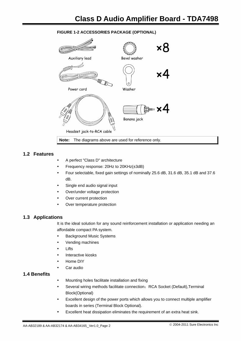
FIGURE 1-2 ACCESSORIES PACKAGE (OPTIONAL)
Note: The diagrams above are used for reference only.
1.2 Features
A perfect "Class D" architecture Frequency response: 20Hz to 20KHz(±3dB) Four selectable, fixed gain settings of nominally 25.6 dB, 31.6 dB, 35.1 dB and 37.6
dB. Single end audio signal input Over/under voltage protection Over current protection Over temperature protection
1.3 Applications
It is the ideal solution for any sound reinforcement installation or application needing an affordable compact PA system. Background Music Systems Vending machines Lifts Interactive kiosks Home DIY Car audio
1.4 Benefits Mounting holes facilitate installation and fixing Several wiring methods facilitate connection:RCA Socket (Default),Terminal
Block(Optional) Excellent design of the power ports which allows you to connect multiple amplifier
boards in series (Terminal Block Optional). Excellent heat dissipation eliminates the requirement of an extra heat sink.
Overview
© 2004-2011 Sure Electronics Inc. AA-AB32189&AA-AB32174&AA-AB34165_Ver1.0_Page 3
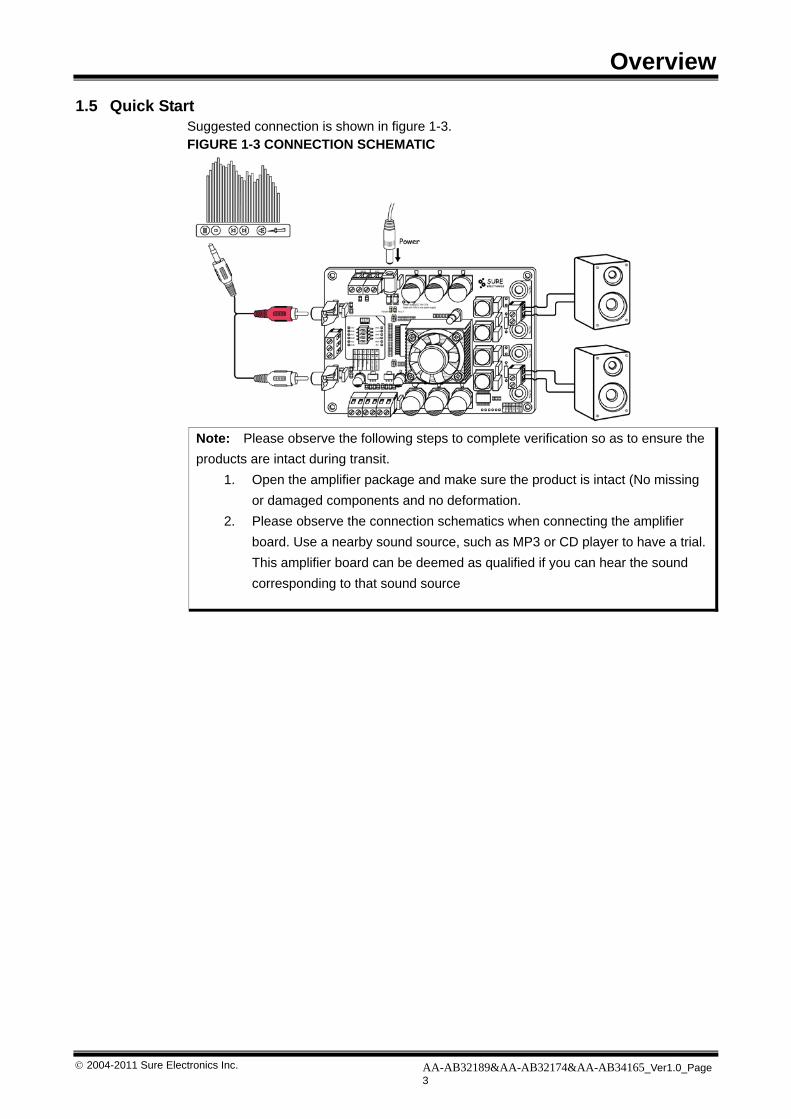
1.5 Quick Start Suggested connection is shown in figure 1-3. FIGURE 1-3 CONNECTION SCHEMATIC
Note: Please observe the following steps to complete verification so as to ensure the products are intact during transit.
1. Open the amplifier package and make sure the product is intact (No missing or damaged components and no deformation.
2. Please observe the connection schematics when connecting the amplifier board. Use a nearby sound source, such as MP3 or CD player to have a trial. This amplifier board can be deemed as qualified if you can hear the sound corresponding to that sound source
Class D Audio Amplifier Board - TDA7498
© 2004-2011 Sure Electronics Inc AA-AB32189 & AA-AB32174 & AA-AB34165_Ver1.0_Page 4
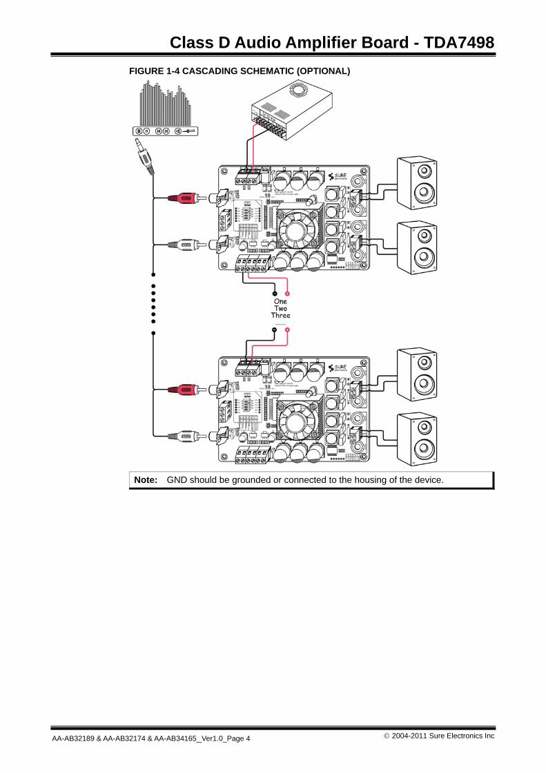
FIGURE 1-4 CASCADING SCHEMATIC (OPTIONAL)
Note: GND should be grounded or connected to the housing of the device.

CLASS D AUDIO AMPLIFIER BOARD - TDA7498
USER’S GUIDE
© 2004-2011 Sure Electronics Inc. AA-AB32189&AA-AB32174&AA-AB34165_Ver1.0_Page 5
2.1 Power Connection
To power the amplifier board, use either jack J9 or terminal blocks J8 (optional). Pay attention to the polarity when connecting power supply. FIGURE 2-1 POWER CONNECTION
TABLE 2-1 POWER CONNECTION
Connector Mark Description
Jack J9 DC power supply socket
VCC The positive of power supply socket Terminal Blocks J8
GND The negative of power supply socket
Note:
1. You are allowed to use only one way to power the amplifier board at a time. 2. The maximum supply voltage shall be referred to Chapter 3.
2.2 Input Connections
You may use RCA connectors to input audio signal.
Chapter 2. Hardware Detail
Class D Audio Amplifier Board - TDA7498
© 2004-2011 Sure Electronics Inc AA-AB32189 & AA-AB32174 & AA-AB34165_Ver1.0_Page 6
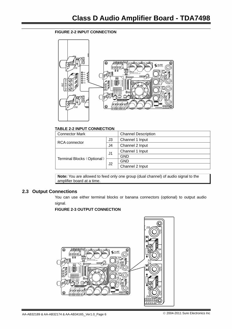
FIGURE 2-2 INPUT CONNECTION
TABLE 2-2 INPUT CONNECTION
Connector Mark Channel Description J3 Channel 1 Input
RCA connector J4 Channel 2 Input
Channel 1 Input J1 GND GND Terminal Blocks(Optional)
J2 Channel 2 Input
Note: You are allowed to feed only one group (dual channel) of audio signal to the amplifier board at a time.
2.3 Output Connections
You can use either terminal blocks or banana connectors (optional) to output audio signal. FIGURE 2-3 OUTPUT CONNECTION
Hardware Detail
© 2004-2011 Sure Electronics Inc. AA-AB32189 & AA-AB32174 & AA-AB34165_Ver1.0_Page 7
TABLE 2-3 OUTPUT CONNECTION
Connector Mark Description J15 Negative Output of Channel 1 J13 Positive Output of Channel 1 J18 Negative Output of Channel 2 Banana Connectors
J16 Positive Output of Channel 2 J14 Output of Channel 1
Terminal blocks* J17 Output of Channel 2
Note:
1. Never connect more than one group of speaker to the audio output 2. Never connect CH1_OUT- 、CH2_OUT- together since they belong to different
NETs. 3. Refer to on-board descriptions for connection details.
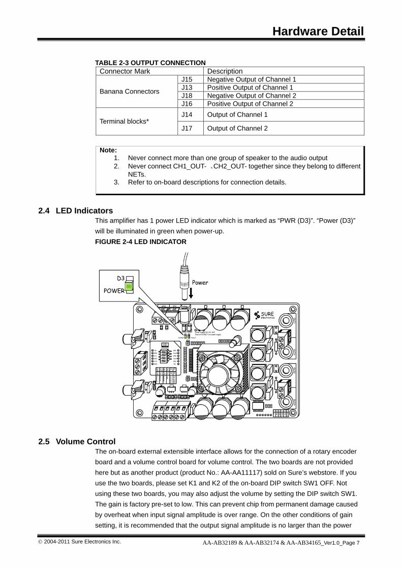
2.4 LED Indicators This amplifier has 1 power LED indicator which is marked as “PWR (D3)”. “Power (D3)” will be illuminated in green when power-up. FIGURE 2-4 LED INDICATOR
2.5 Volume Control
The on-board external extensible interface allows for the connection of a rotary encoder board and a volume control board for volume control. The two boards are not provided here but as another product (product No.: AA-AA11117) sold on Sure’s webstore. If you use the two boards, please set K1 and K2 of the on-board DIP switch SW1 OFF. Not using these two boards, you may also adjust the volume by setting the DIP switch SW1. The gain is factory pre-set to low. This can prevent chip from permanent damage caused by overheat when input signal amplitude is over range. On the other conditions of gain setting, it is recommended that the output signal amplitude is no larger than the power
Class D Audio Amplifier Board - TDA7498
© 2004-2011 Sure Electronics Inc AA-AB32189 & AA-AB32174 & AA-AB34165_Ver1.0_Page 8
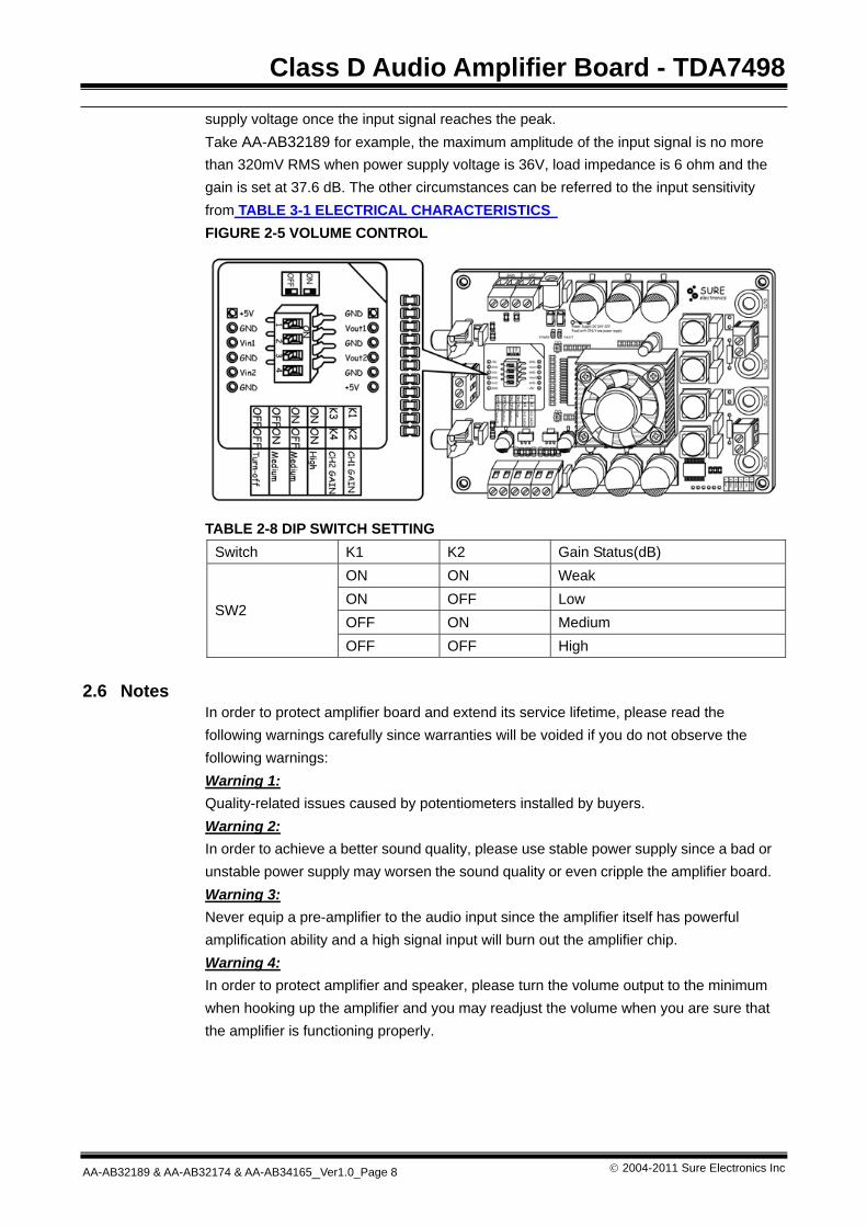
supply voltage once the input signal reaches the peak. Take AA-AB32189 for example, the maximum amplitude of the input signal is no more than 320mV RMS when power supply voltage is 36V, load impedance is 6 ohm and the gain is set at 37.6 dB. The other circumstances can be referred to the input sensitivity from TABLE 3-1 ELECTRICAL CHARACTERISTICS FIGURE 2-5 VOLUME CONTROL
TABLE 2-8 DIP SWITCH SETTING
Switch K1 K2 Gain Status(dB) ON ON Weak ON OFF Low OFF ON Medium
SW2
OFF OFF High 2.6 Notes
In order to protect amplifier board and extend its service lifetime, please read the following warnings carefully since warranties will be voided if you do not observe the following warnings: Warning 1: Quality-related issues caused by potentiometers installed by buyers. Warning 2: In order to achieve a better sound quality, please use stable power supply since a bad or unstable power supply may worsen the sound quality or even cripple the amplifier board. Warning 3: Never equip a pre-amplifier to the audio input since the amplifier itself has powerful amplification ability and a high signal input will burn out the amplifier chip. Warning 4: In order to protect amplifier and speaker, please turn the volume output to the minimum when hooking up the amplifier and you may readjust the volume when you are sure that the amplifier is functioning properly.
CLASS D AUDIO AMPLIFIER BOARD - TDA7498
USER’S GUIDE
© 2004-2011 Sure Electronics Inc. AA-AB32189 & AA-AB32174 & AA-AB34165_Ver1.0_Page 9
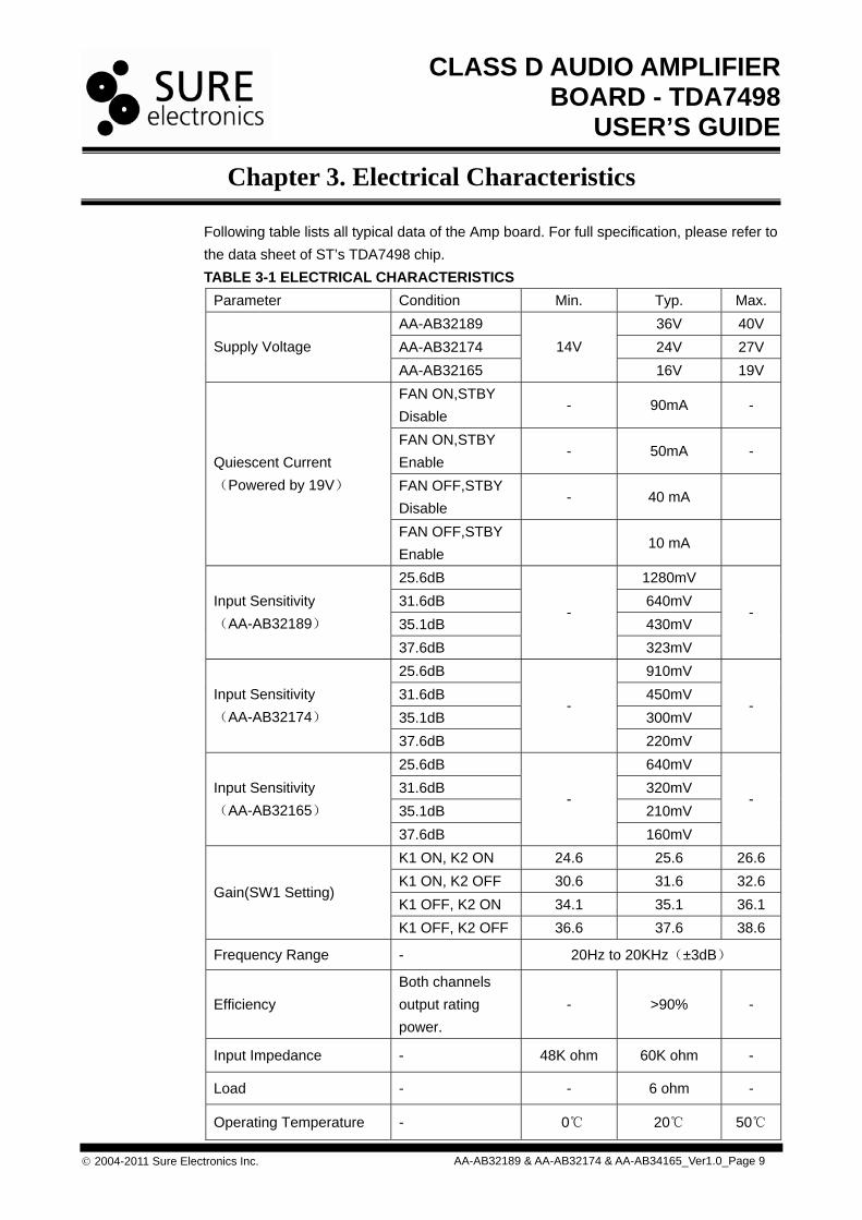
Following table lists all typical data of the Amp board. For full specification, please refer to the data sheet of ST’s TDA7498 chip. TABLE 3-1 ELECTRICAL CHARACTERISTICS
Parameter Condition Min. Typ. Max. AA-AB32189 36V 40V AA-AB32174 24V 27V Supply Voltage AA-AB32165
14V 16V 19V
FAN ON,STBY Disable
- 90mA -
FAN ON,STBY Enable
- 50mA -
FAN OFF,STBY Disable
- 40 mA
Quiescent Current (Powered by 19V)
FAN OFF,STBY Enable
10 mA
25.6dB 1280mV 31.6dB 640mV 35.1dB 430mV
Input Sensitivity (AA-AB32189)
37.6dB
-
323mV
-
25.6dB 910mV 31.6dB 450mV 35.1dB 300mV
Input Sensitivity (AA-AB32174)
37.6dB
-
220mV
-
25.6dB 640mV 31.6dB 320mV 35.1dB 210mV
Input Sensitivity (AA-AB32165)
37.6dB
-
160mV
-
K1 ON, K2 ON 24.6 25.6 26.6 K1 ON, K2 OFF 30.6 31.6 32.6 K1 OFF, K2 ON 34.1 35.1 36.1
Gain(SW1 Setting)
K1 OFF, K2 OFF 36.6 37.6 38.6
Frequency Range - 20Hz to 20KHz(±3dB)
Efficiency Both channels output rating power.
-
>90% -
Input Impedance - 48K ohm 60K ohm -
Load - - 6 ohm -
Operating Temperature - 0℃ 20℃ 50℃
Chapter 3. Electrical Characteristics
Class D Audio Amplifier Board - TDA7498
© 2004-2011 Sure Electronics Inc AA-AB32189 & AA-AB32174 & AA-AB34165_Ver1.0_Page 10
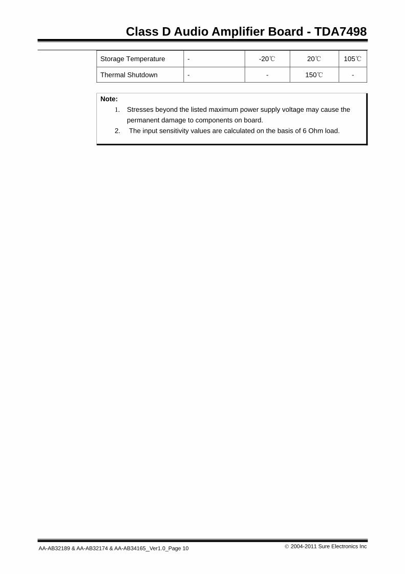
Storage Temperature - -20℃ 20℃ 105℃
Thermal Shutdown - - 150℃ -
Note:
1. Stresses beyond the listed maximum power supply voltage may cause the permanent damage to components on board.
2. The input sensitivity values are calculated on the basis of 6 Ohm load.

CLASS D AUDIO AMPLIFIER BOARD - TDA7498
USER’S GUIDE
© 2004-2011 Sure Electronics Inc. AA-AB32189 & AA-AB32174 & AA-AB34165_Ver1.0_Page 11
FIGURE 4-1 MECHANICAL DRAWING
Chapter 4. Mechanical Drawing
CLASS D AUDIO AMPLIFIER BOARD - TDA7498
USER’S GUIDE
© 2004-2011 Sure Electronics Inc. AA-AB32189 & AA-AB32174 & AA-AB34165_Ver1.0_Page 12
Sure Electronics Co., Ltd. East zone, 3F, Building 6 Jingang Technology Innovation Center No.108 Ganjiabian Rd (ZIP: 210000) Qixia District Nanjing P.R.China Tel: +86-25-68154800-860 Fax: +86-25-68154891-832 Website: www.sure-electronics.com Email: [email protected]
Chapter 5. Contact Us