city of somerville capital projects and planning ... hill tower_with... · capital projects and...
TRANSCRIPT

PROSPECT HILL TOWER
CPA FUNDING APPLICATION PACKET
City of Somerville
capital Projects and Planning Department
Stephen Vitello, Project Manager- 12/1/14

GENERAL
• CoverPage
• Checklist
• Narratives
• Tfmeline

JOSEPH A CURTA TONE
MAYOR
1. PROJECT INFORMATION
CITY OF SOMERVILLE, MAsSACHUSETTS
COMMUNITY PRESERVATION COMMI1TEE
FY15 FUNDING APPLICATION
COVER PAGE
PROJECT NAME: Prospect Hill Tower Renovation
PROJECT LOCATION: Munroe Street
Open Spa<t All'orcloblt Historic Rtae.llion Howlnc J>Jestrvotion
lEGAl PROPERTY OWNER OF RECORD: City of Somerville --~----------------------------------------------
ONE SENTENCE DESCRIPTION oF PROJECT: Replace upper level floor slab, reset parapet stones, restore doors and
ornamental iron stairs, repoint facade, repair exterior stairwell.
Please indicate (X) the approved category(s) from your Eligibility Determination Form.
ESTIMATED START DATE: 9/1/15 --------ESTIMATED COMPlETION DATE: 12/1/15
CPA FUNDING REQUEST: _$_5_0_0_,0_0_0 _____ _
TOTAl BUDGET FOR PROJECT: $532,600
2. APPUCANT INFORMATION
APPliCATION NAME 1 ORGANIZATION: Stephen Vitello - Somerville Capital Projects and Planning Dept.
CO-APPliCATION NAME I ORGANIZATION:---------------------------
CONTACT PERSON: Stephen Vitello - Project Manager
MAiliNG ADDREss: 1 Franey Rd. Somerville, MA 02145
PHONE: 8'5?-523 ... /tJg: 6 EMAil: [email protected]
3. SIGNATURES
I (we) certify that all information provided in this entire submission Is true and correct to the best of my (our) knowledge and that no information which might reasonably affect funding has been excluded. I (we) authorize the Community Preservation Committee and/or the City of Somerville to obtain verification from a ov· ed
Name (printed) s7'£1/J/€JJ 1/ f775Zio Signatu-..c_::::._:..J,_V,1:-....~oc...=:.._:::::::...,_ __ """"o::::.._ ____ _ Date a/t/li Name (printed)----------- Date _____ _
fOR CPC USE: Date Received ___ _ Date Reviewed ___ _ Date Applicant Notified ___ __
20
Somerville CPA ~ ~. m~ JDD- •
CITY OF SOMERVILLE, MAsSACHUSEITS
COMMUNITY PRESERVATION COMMITTEE
FY15 FUNDING APPLICATION
SUBMISSION REQUIREMENTS CHECKLIST
Open~ Alrord•blt Histork Rtcrution
JOSEPH A. CURTA TONE
MAYOR
t louslna l'reserv•tion
Please check (,f) each item included in your submission, which should include the applicable items in the order listed below.
~RAL: ~ fPplication Cover Page (form provided)
Ul}ubmisslon Requirements Checklist (this form)
[B'J4arratives (prompts provided)
li2f Project timeline: a project schedule showing all major milestones (i.e., study, design, environmental, permitting, construction, etc.), including receipt of other funding sources
fl~ fZJJJudget Summary (form provided)
temized budget of all project costs, including the proposed source for each cost
t least two written quotes for project costs. If quotes cannot be secured, detailed cost estimates may be used if a thorough explanation of the estimates is included.
0 Proof of secured funding (e.g., commitment letters or bank statements), if applicable
Vrs~ · 0 ~ap of the property location showing all features pertinent to the project, including current or future rapid transit - )tations
[;2f Photos of the project site (not more than 4 views per site); include digital copies
OWNERSHIP/OPERA nON (NON-CITY):
O Documentation of site control or written consent of the property owner to undertake the project, if the owner is not the applicant
0 Certificate of Good Standing from the City, if applicable
0 501(c)(3) certification, if operating as a non-profit
0 Purchase and sale agreement or copy of current recorded deed, if applicable
C.UNITY SUPPORT (RECOMMENDED):
fiZ] letters of support from residents, community groups, other City boards, commissions, or departments, or from City, state, or federal officials
HrsTforc REsouRCES PROJECTS:
g Documentation that the project is listed on the State Register of Historic Places or a written determination from the Somerville Historic Preservation Commission that the resource is significant in the history, archeology, architecture, or
/ulture of Somerville.
0" Jhotos documenting the condition of the property
0 Report or condition assessment by a qualified professional describing the current condition of the property, If available.
PLANS AND REPORTS (IF AVAILABLE)
[if a~lable in 8>S x 11, include in the application. If not, include separately, not bound to the application)
~Renderings, site plans, engineering plans, design and bidding plans, and specifications
0 Applicable reports (e.g., 21E, historic structure report, appraisals, survey plans, feasibility studies). Note: for reports of more than 10 pages, applicant may provide 2 copies, rather than 11.
19
Prospect Hill Tower CPA Narrative
Project Description
1. THE PROJECT
Prospect Hill Tower is a historic landmark located in a local Historic District on Prospect Hill
Parkway in Somerville, MA. The tower commemorates the location as a Revolutionary War
encampment and fortification where the first American flag was raised. Currently, the tower is
not safely accessible by the public. The proposed project would encompass the replacement of
the upper level floor slab and flagpole mounting, resetting of the parapet stones, repainting the
stone exterior, restoring the interior iron circular stairs and entrance door, and resetting the
granite wall at the exterior stairs.
2. NEEDS AND PUBUC BENEFITS
Prospect Hill Tower is a significant and beloved landmark that presently cannot be used due to
safety concerns. It has not had any significant restoration in its 100+ year life. Prospect Hill
Tower and the Powder House in West Somerville are the two most recognizable historic
landmarks in the city. Their images are constantly reinforced on letterheads, in publications,
and at various events. The preservation of such a local (and national) icon is central to
preserving Somerville's public identity. A restored tower would make it accessible to the public
once again and solidify the structure for use well into the future.
3. COMPUANCE WITH CPA PRIORmES
CPA Priority 1-Consistency With Community Values
A. Improve Accessibility for All
The Prospect Hill Tower is inaccessible to the public in its present condition because safety
issues preventing the use of its tower. The proposed project will address these concerns so
that the site can once again be accessible for all.
B. Incorporate Sustainable Practices and Design
The proposed work is a restoration of the existing tower elements. There are no new
features being designed. All masonry, concrete and ornamental iron work will mainly
consist of refurbishing and stabilizing existing features. The design emphasizes thorough
and durable details that maintain original mortar color and stone placement.
C. Endorsements
The Prospect Hill Tower stabilization is endorsed by the mayor and is identified in
Somerville's Five Year Capital Improvement Plan. The project is also endorsed by the
Somerville Historic Preservation Commission in a letter which is attached to this application.
D. Consistency With Other Goals and Priorities
The Prospect Hill Tower Project is consistent with tl:le mayor's st~ted goal of ~a king
Somerville a great place to live, work, pl.ay, qn~. raise a family. Tt:le project will give the
pyblic the opf?Ortunity to acces.s and appreciate a sig~ificant landmark commemorating the
history of Somerville and the United States. The Towe.r is the centerpiece of the Prospect
Hill Park, which is also identified for restoration in the Somerville Five Year Capital
Improvement Plan and complements the CPA's Open Space priority a.rea.
E. Addresses Two or More CPA Focus Areas
The Prospect Hill Tower is a significant historic resource as it sits on a site of strategic
importance in the American Revolution. The project is consistent wi~h the CPA's upcoming
plan to identify and protect historic resources. A~ditianally, the tower complements the
CPA focus area ()f Open Space and Recreational t.and, since it sits in the middle of Prospect
Hill Park, a historic passive recreation area. The completion of the tower stabilization will
enhance the entire site and will allow future park improvements to take place without
disruption from tower work.
CPA Priority 2 - Strategic Use of CPA Funds
A. leverage Other Funds, implement Cost-Saving Measures
The City of Somerville has funded the design portion of the Prospect Hill Tower project. It
seeks to leverage this expenditure with a commitment from the CPA Committee to fund the
restoration.
B. Address long-Standing or Urgent Needs in the Community
The Prospect Hill Tower is a valuable community resource that is at risk from age and the
elements. For several years It has been Clos~d to the public and has had no restoration.
There is a need to restore and preserve existing historic resources so they can remain
functional and a source of civic identity and pride.
C. Exceptional, Time-Sensitive Opportunities
Undertaking the tower restoration at this time would allow the CPA Committee to take
advantage of low interest rates and to capitalize on Somerville's enhanced bond rating.
Delaying the work deprives the public of full enjoyment of the tower and exacerbates
existing safety issues.
D. Catalyst for Transformative Change
As Somerville continues to experience significant changes in infrastructure, development,
and investment, it is important to preserve significant elements of its past. The restored
tower would remain strong for the foreseeable future, helping ground any changes in
Somerville's historic past.
Financial
1. FUNDING
The City of Somerville has identified the Prospect Hill Tower project in its Five-Year Capital
Improvement Plan (CIP). The City has funded the design work and is applying for one time CPA
support to enable the tower stabilization and restoration to happen while maximizing the ability
to fund as many needed capital improvements as possible.
2. DETERMINATION OF AMOUNT REQUESTED
The $500,000 CPA funding request represents the construction estimate prepared by the design
firm TBA Associates. We added an additionallO% contingency to cover any increases in
construction prices at the time of bid. We feel the amount of CPA funding requested is
cognizant of the limited CPA funds available compared to the great number of applications
submitted.
3. FUNDING REQUIREMENTS
The entire project will be funded at one time, with no funding required over multiple years.

Project Management
1. APPUCANT
The applicant is the Somerville Capital Projects and Planning Department (CPPD), a public entity
responsible for the management, maintenance and capital improvements for City buildings.
2. PROJECT EXPERIENCE
Prior <;:PPD work has encompassed successful renovations as well as new construction of . .. . . . . .
s~hoo!s, administrativ~ buildings, recreation centers, public safety buil~ings, and libraries. The
design firm associated with the Pro$pect Hill Tower project. has extensive preservation, and
historic restoration experience.
3. PARTICIPANTS' ROLES
The Somerville Capital Projects and Planning Department (CPPD) will be responsible for the
implementation of the project. CPPD and the designer will monitor the progress and quality of
the construction work.
4. FEASieiUTY
The Prospect Hill Tower project is feasible because it is not o~cupied and it sits in an open area
which allows the work area to be clearly delineated and the work to be performed safely within
the stated timeline.
5. POTENT;IAL BARRIERS
The Prospect Hill Tower project does not face any known or potential barriers to the
commencement or completion of the project: The project has received a certificate of non
applicability from the Somerville Historic Commission.
6. ONGOING MAINTENANCE
Upon completion of the wqrk, the building will be maintained by in-house maintenanc;e staff.
Specific maintenance duties would include cleaning of the interior and surrounding grounds,
repair of any caulking at the exterior stairs, and touch-ups on painted surfaces. The tower will
be placed on a preventive maintenance program, undergoing regular inspection of its
components, including an annual binocular inspection of the exterior fa~ade and pointing.

Historic Resources Rehabilitation Projects
1. COMPLIANCE WITH U.S. SECRETARY OF INTERIOR STANDARDS
The Prospect Hill Tower project will comply with the U.S. Secretary of the Interior's Standards
for Rehabilitation because:
• The property will continue its original and historic use as a public landmark.
• Its historic character will be preserved by developing and implementing a design which
keeps distinctive original features.
2. ONGOING COMPUANCE
The City of Somerville will comply with the U.S. Secretary of the Interior's Standards for
Rehabilitation by reviewing them with the designer. The firm has preservation experience and is
quite familiar with the property. Their design is attached and it calls for keeping original
features. Any new materials such as the concrete floor slab, new mortar, and paint shall be
closely monitored throughout the course of the work to be sure they match existing finishes.
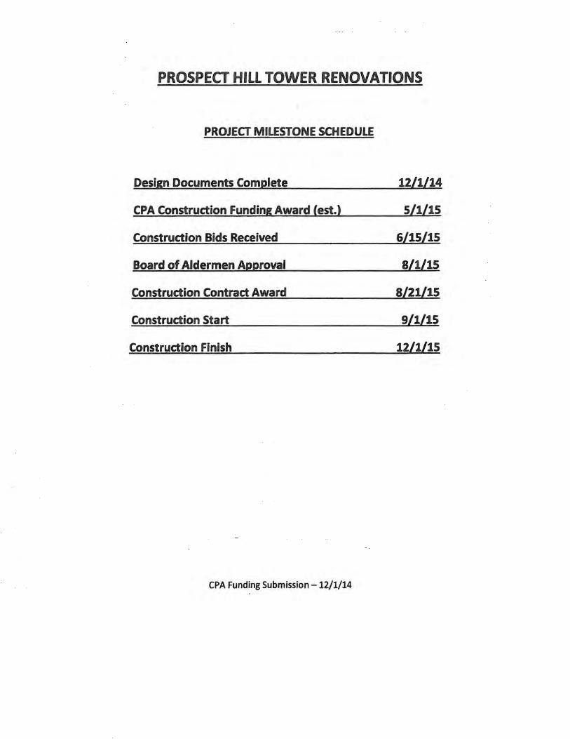
PROSPECT HILL TOWER RENOVATIONS
PROJECT MILESTONE SCHEDULE
Design Documents Complete 12/1/14
CPA Construction Funding Award (est.) 5/1/15
Construction Bids Received 6/15/15
Board of Aldermen Approval 8/1/15
Construction Contract Award 8/21/15
Construction Start 9/1/15
Construction Finish 12/1/15
CPA Funding Submission - 12/1/14

FINANCIAL
• Budget Summary
• Itemized Budget
• Cost Estimates
Somerville CPA
-• l.• ~~~ ~;
IIDI- • CITY OF SOMERVILLE, MASSACHUSETIS
COMMUNITY PRESERVATION COMMITI'EE
FY15 FUNDING APPLICATION
~ Spoott Atford.ablt llistoric ~rion
jOSEPH A. CURTA TONE
MAYOR
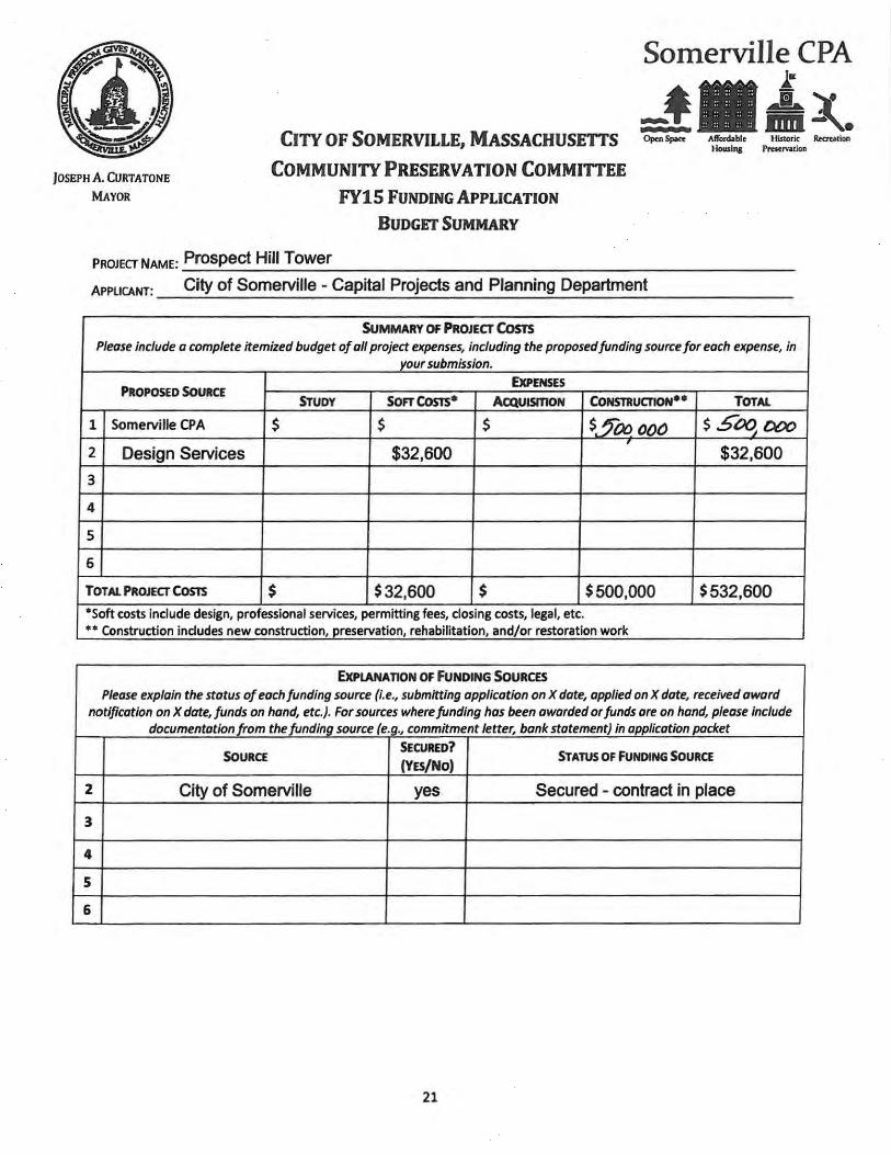
PROJECT NAME: Prospect Hill Tower
BUDGET SUMMARY
APPLICANT: City of Somerville- Capital Projects and Planning Department
SUMMARY OF PROJECT Com
ll01111zll J'raen"Otion
Please include a complete itemized budget of oil project expenses, including the proposed funding source for each expense, in your submission.
PROPOSED SOURCE ExPENSES
STUDY SOFT COSTs* ACQUI5mON CoNmuatoN** TOTAL
1 Somerville CPA $ $ $ $§a:? 0()() $5~tXXJ 2 Design Services $32,600 $32,600
3
4
5
6
TOTAL PROJECT COSTS $ $32,600 $ $500,000 $532,600 •soft costs include design, professional services, permitting fees, closing costs, legal, etc. •• Construction includes new construction, preservation, rehabilitation, and/or restoration work
ExPLANATION OF fUNDING SoURC£S
Please explain the status of each funding source (i.e., submitting application on X dote, applied on X date, received award notification on X date, funds on hand, etc.). For sources where funding has been awarded or funds ore on hand, please include
documentation from the funding source (e.g., commitment letter, bonk statement) in application packet
SOURCE SECURED?
STATUS OF fUNDING SOURCE (YES/NO)
2 City of Somerville yes Secured - contract in place
3
4
5
6
21
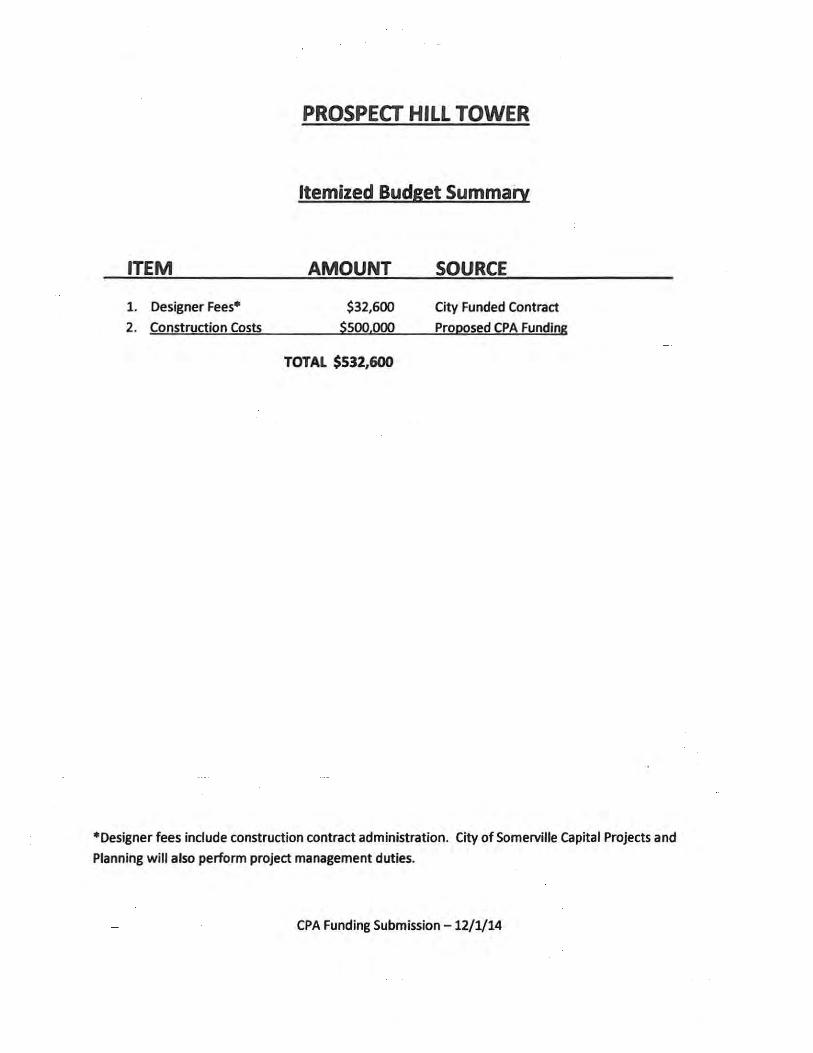
ITEM
1. Designer Fees*
2. Construction Costs
PROSPECT HILL TOWER
Itemized Budget Summary
AMOUNT
$32,600
$500,000
TOTAL $532,600
SOURCE
City Funded Contract
Proposed CPA Funding
*Designer fees include construction contract administration. City of Somerville Capital Projects and
Planning will also perform project management duties.
CPA Funding Submission - 12/1/14

Unlfoml.t Ref. No.
DIO
E
E10
uo
F
~pontnt
!lectrtcel
Equipment& Furnishings
ECIUID!Mnt Flagpole
,~
Other Building Construction
G BullcllngSJteWOrt(
no-'t
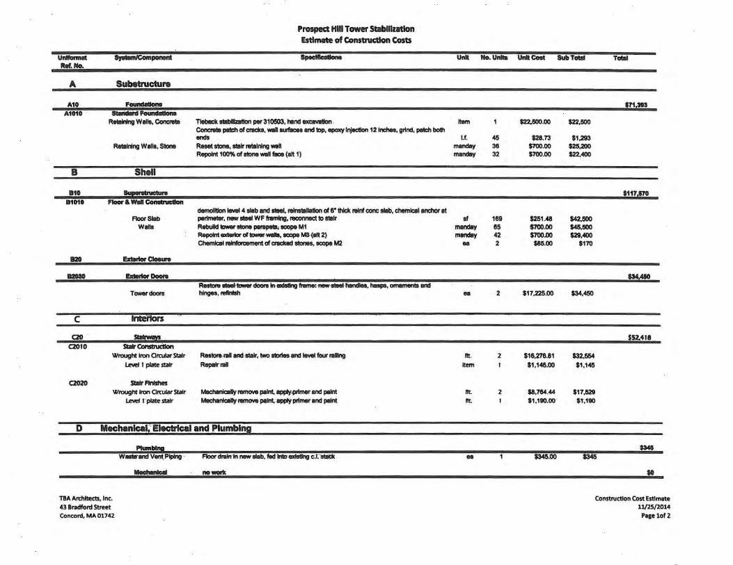
Prospect Hill Tower Stabilization Estimate of Construction Costs
~·
Removal end ntlnstallallou ofn.gpole (cntne below); storage by city Reinstall existing mounting piiiW and mw giiY stilet sleeYe, leYel 4
no-'t
Not used
Unit No. Unlta Unit Colt Sub Teal
Item Item
$1,150o.oo $8e0.00
$1,1500 $&SO
T ..
so
suso
so
G20 l*lrfti!Rit- $27.121 Snet Sllllr Ralls RIIIIIOYe 1'1111. ..... and rellnllh, A1111t Into giW1Ite Willis l.f. 65 $3711.00 $24;375
Reeet winder stlln Reset I1Dne Slips, lntlft wtlh mw concrete Item 6 $525.00 $3,1 !50 SldeW81ks no WOIIt $0
Paving no work $0 Landlcape no work $0
......... eon.tructloftWICot ..... \lniiiiiUitiiCI - - --- -- - - - - - - - ----- S30I,OSO
$43,712 o....e Conclltlons acafrold Item $20,000
soils testing Item $2,600 moltllr testing Item $5,162 cntne day 6 $1,7&>.00 $10,!500 other Item $11,600
GeMnl Connctor's o-tiHd end Profit 25.0% $78,113
TOTAL U11MAtaD CON5mUCl10N COlT ~
10.0% $42,132
UCOIIlll!NDeO CONsmUCllON BUDGeT (ROUNDeD) .... ,000
TBA Architects, Inc. 43 B111dford Street Concord, MA01742
Construction Cost Estimate 11/25/2014
Psse 2of2
UnlfanMt Rtf. No.
~poneitt
A Sub8tructure
Prospect Hill Tower Stlblllzltlon EstltMte of Construction Costs
Unit No. Units Unit Cost Sub Teal Teal
A10 Foundllllons $71,31S A1010-.-- ..-..~
Retaining Willa, eoncr.te 11ebllcl< l1lbllzallo11 per 310503, l'anchxcavdon . Jtem 1 $22.1500.00 $22,1500 Concnltl pft:h of crKka, Mil~ and top, epoxy lr1e<:tlon 121nches, grind, pft:h both ends l.f. 45 $28.73 $1,293
Retllnng Walls, Stone Reset sUn~, stair ...talnlng wei manday 38 $700.00 $25,200 Repaint 100% of stone weir- (8111) manday 32 $700.00 $22...00
B Shell
810 ~ $117,Jl'O 111010 F1oor&W .. CcinMnlclan
Floor Slab Wlllll
1120 !ldaftor Cloewe
demolition level4 slab and steel, relns1alla1lon of 8"1hlck relnf cone llllb, chemical anchor at perimeter, ,_ IIMl WF framklg, raconnact to Sllllr Rebuild "-IIDM ~.cope M1 Repaint exwrtor of tower- Willi, aoope Ma·(tllt 2) Chemical reluboament of c:racted stones, aoope M2
af mandly rnanday
ea
189 85 42 2
$251.48 $700.00 $700.00
$85.00
$42,1500 $45,1500 $29,..00
$170
112010 !ldaftor o-. $MMO
T<Merdoonl Renn ... -. doonllnllldlllng hme:·neW-siMifilttldlM, t.spa, 01TWM1111 and hinges, rellnlsh •• 2 $17,225.00
c ~- - ----- --··------~
tJRCJIUt~
czo . ~
CZOIO Slalr ConstNdton
CZ020
Wrought Iron Orcular Stair
l.e¥el I plate stair
Slalr Finishes
ReatonuaiiiAd·lltlllr, two etorleund levelfturallng Repelrral
Wrought IrOn Orcular Stair Mechllnlcally I'8I'AOII8 .paint, 8CIPIY.prlmer and paint
l.e¥el tplate stair Machaukally ramOYII paint, 8CIPIY primer and paint
o-Mec:lMiriiCIII;EIKtiical and Plumbing
T8A Architects, Inc. 43 Bradford Street Concord, MA01742
Plumbing
Wllltll'and Vant. Piping · ........ Flool' diilrrlft neW alab, fed !rib ilodtl1lng c.t:·stliti(
no-'l
lit. Item
lit. lit.
..
2
2
$1&,276.81 $1,14&.00
$8,784:44 S1,190.oo·
$346:00
$34,450
$32,554 $1,14&
$17,529 $t,190
$3415
$52.418
$341
to
Construction COst Estimate 11/25/2014 Pace 1of 2

!(éç
!(éç
Prospect Hill Tower
Union Square
Washington Street
MC
GR
ATH H
WY
WASHINGTON ST
JOY ST
SOMERVILLE AVE
BOSTON ST
GLEN
ST
MUNROE ST
TUFTS ST
OLIVER ST
WAL
NUT
ST
LINWOOD ST
FLINT STCROS
S ST
FRAN
KLIN
ST
PRO
SPEC
T ST
COLUMBUS AVE
WEBSTER
AVE
ALLE
N S
T
STONE
AVE
LIN
DEN
ST
HAM
LET
ST
DELL ST
MAN
SFIELD
ST
ALSTON ST
POPLAR ST
UNION SQ
WARREN AVE
GREE
NVIL
LE S
T
NEWTON ST
MER
RIA
M ST
CHESTNUT ST
FOUNTAIN AVE
FRA
NKL
IN A
VE
RO
SSM
OR
E ST
AUBURN AVE
CHESTER AVE
BON
NER
AVE
SUMMIT AVE
KNO
WLT
ON
ST
PROSPECT HILL AVE
THO
RPE
ST
PLEASANT AVE
MORTON ST
BENNETT ST
WAS
HIN
GTO
N A
VE
WAS
HIN
GTO
N T
ER
MEDFORD ST
AVON PLSA
NBO
RN
CT
TURNER CT
MIL
K PL
HADLEY CT
REE
D CT
PALMER AVE
GREENVILLE CTM
ERR
IAM
STKN
OW
LTO
N S
T
MC
GR
ATH
HW
Y
MC
GR
ATH H
WY
Department of Public WorksEngineering Division
1 Franey RdSomerville, MA 02145
PROSPECT HILL TOWERAND PROPOSED MBTA
GREEN LINE EXTENSION
Date: December 1, 2014Source: MassGIS
The information contained in this mapis compiled from multiple sources andis believed to be accurate butaccuracy is not guaranteed. This mapdoes not replace information obtainedby consulting the information's officialsource or originating City department. In no event shall the City of Somerville, Massachusetts be liable for any damages, direct or consequential, from the use of the information contained in this map.
C:\GIS\Projects\Somerville\DPW\ProspectHillTowerAndProposedGreenLine.mxd 2014-12-01 KJJ
²0 200 400100
Feet
_̂
Parcel Boundary
Rail Road ROW
Proposed Green LineExtension


COMMUNITY SUPPORT
• Letters of Support

CITY OF SOMERVRLE, MAsSACHUSEITS OFFICE OF STRATEGIC PLANNING AND CoMMUNTIY DEVELOPMENT
JOSEPH A. CURTA TONE MAYOR
HISTORIC PRESERY.A.110N COMMISSION
November 18, 2014
Community Preservation Commission 93 Highland Avc:nue Somerville, MA 02143
RE: Support for projects funded through the Community Preservation Act
Dear Community Preservation CoJIUDission members,
The Somerville Historic Preservation Commission fully supports four projects the City of Somerville bas proposed to the Community Preservation Commission. These projects are: 1) restoration of Prospect Hill Tower; 2) restoration of City Hall; 3) renovation of West Branch Libnuy; and 4) National Register nomination for the American Tube Worb Complex.
These buildings and complex are historically and architecturally significant to the City of Somerville. Prospect Hill Tower was constructed in the early 20dl century to commemorate militia located at this site during the Revolutionary and Civil wan~. City Hall was constructed in 1852 as Somerville's first high school; town offices took over the building in 1872. Andrew Carnegie donated $25,000 in 1907 to construct the West Branch Library, a high and Classical Revival style building. The American Tube Worlcs Company is credited as being the first In America to manufacture seamless tubes; as a collection of buildings, their scale and architecture express the manufacturing purpose and magnitude of the industrial process. Prospect Hill Tower, City Hall and the West Branch lJbrary are local )listorlc districts; the American Tube Works was determined Significant by the HPC in September.
The Historic Preservation Commission hopes the Community Presavation Commission will recognize these to be valuable investments that will benefit the entire community. Thank you for your consideration of these projects.
i ..,
Geo roakis, Director ofPlaoning, OSPCD Stephen Vitello, Project Manager, Department of Public Works
CrrY HALL • 93 HJGHLAND A VENUE • SoMERVJLI.E, MAssACHUSHITS 02143 (617) 625-6600ExT.2500•TIY: (617)666-0001•FAX: (617)625-0722
EMAlL: [email protected] • www.tomervllle.ma.aov

HISTORIC RESOURCES
• Historic Documentation

101~ nnv 25 P 3; 2b
r'ITY CLERK'S OFfiCE .. SOHERVIl.LE. MA
CITY OF SOMERVILLE, MAsSACHUSEITS
OFFICE OF STRATEGIC PLANNING & COMMUNITY DEVELOPMENT JOSEPH A. COKTATONE
MICHABL F. GLAVIN EXEctmvB DlRECroR
JIISrORJC PRESERY.4TJON COMMISSION
N<MIDber 19, 2014
Stephcm Vitello, Project Manager Capital Projects City of Somerville 93 Hiahland Avame Somerville, MA 02143
MAYOR
R.e: BPC 2014.075- Prospect BDl Tower, Somerville
Mr. Vitello,
Certific:ate of Non-ApplleabBlty
The Historic Preservation Co.IIUIIission (HPC) receiv~ your application dated September 4, 2014 for a Historic Diltrict Propaty Certificate. After a rcvi5 of the application aDd a .UC visi~ Staff made a determination that the Prospoct Bill Tower Stabilization as deacri'bed in the Technical Sections Submittal, and Plan Sheets, A-1.0, A-2.0, A-3.0, A-4.0 by TBA Arcliliccta, IDe. dated November 14, 2014 with in-kind and other materials to match the existing arc exempt from review by the HPC due to being categorized UDder o.rdinaly maintmanoe, repair, or repliCCIDCIIt, or DOt visible from the public dgbt of way. In accordaDoe with the Hiltoric Diltrlct Ordinance and the Application received, the BPC grudla Ctriflcate ofNo&-ApplleabDJty to the AppllcaD.t, Stepllea VItello, Project Mauger.
The soope of wm:k as 1iltm in the Memo prepared by TBA Arcbitects aDd dated July 17, 2014 detaiJB the following in-kind repairs audlor maintmance:
1. Construct a new concrete slab on the top level, replace the floor's existing stecliJUpport beams, and watclprooftbe sJab surface. .
2. Repair BDd wat« proof the lower level slab. 3. Remove aDd reinstall the flagpole. 4. Repair the roof drain system. S. Repair the spiral stair imd railings, and repair the lower level steel diamood plate stair rail 6. Rebuild the parapet 8toDc8 where they have lost their mortar. 7. Repair the two tower iron doors and frames. 8. Repoint portions of the tower extaiat. 9. Reset and stabilize the atone wall along the street stair. RqMlir and reset the wrought iron nil. 10. Repair the concrete rcUining wall aloug side of the stair.
--..
'
CITY HAU • 93 HIGHLAND AVENUE • SOMERVILLE, MAsSACHUSETI'S 02143 (617) 625-6600 ExT. 2500 • TTY: (617) 666-0001 • FAX: (617) 625..0722
_ www.somervfllema.gov

HPC 2014.075- Prospect Hill Tower, Munroe Street · 2
This scope is detailed on the plan set (Sheeti ~-1.0, · A.:-2,0, A-3.0, A-4.0 by TBA Architects, Inc. dated November 14, 2014) upon whirb this~ -Q(N~-Appli~ is contingent:
1. RCDK>ve and reset stones on the parap~~ m.m _.wroase as indicated on Sheets A-1.0, A-2.0, A-3.0 and A-4.0, .. .
a. All stones to be reinstalled in originil 'loCation. 2. Epox)r uyection in amck between levels 3 and 4 on the southeast and northwest elevations as indicated
on shceta A-1.0, and A-2.Q. . 3. llqK)iDt all extCrior stblle siufaces, all mces of tower where stones are not reset as indicated on Shcet.s
A:l.Q,A-:-2.0~A-3.0Q.Dd~~.O. ... · . . . . · 8. Mortar to match existing in j~int ciinleniion .apd surface finish. (Alt. 2)
4. Seal craeb on top of retaining wall a81oaiaite4 on~ A-2.0. S. Patch expo8ed filce of concrete r«ahring waD ·u Didicated on ahoet A-3.0.
a. Prime & paint to match cxistiog. 6. Wrought iron grilles to be removed and resd with mortar in stone in originallocatiOils lis indioatCa on
sheets A-2.0 and A-3.0 . . 7. Stabilize bottom section of retaining wall south elevation east aide as indicated on shcets A-2.0 and .A-
3.0 • See Spec Section 310503. · · · · 8. Cut existing ltec:ll pipe rail at or above existing flanges. Rail to be out aad J:aDOved by~ irpn
reskntion suhcontractor. Clean, grind to clean meCal, weld, prime and paint two coats~ 'Poit ~ of same diameter to be inlet into granite after rebidding as iDdicatod on~ A-2,0 ~ A-'13.0 .
9. From stairway elevation (Plan Sheet A-3.0) a. Masonry Detail
i. Remove rail sections for refinishing. ii. Reinstall on adjusted posts after gnmitc has been reset. iii. New chcmi~ ~hors in two locations, all posts inst!t in original flqes iv. Patchbotcafiocmii'iildemttlfll · · ! ·
v. Mason to drill through flange & into granite fl' deep to receive post vi. Coordina~ ~ locaqon with wrought iroJ;l restoration contractor
vii. ~Oitar·baQk'I*Jd tQ itillfilizc spil & bed to coritinuoUi·diatkjohit vtii. Reletpdtcas~6n:~ · .
ix. Vi'ltift ~ ·afc· ti&l# to ~rig'~ ·cHg out joiilt tO 2" depth ~Or mortar joint L COniimoua ~Dottat Jtilnt tuD~U:ng ·a~~ ttac~ arid riSers
l =~~m:=~th~~· xiii; twMmg conctctc ·~ tO R:lb8iii . . . xiv. Stabilize soil XV. fQfitjpn~~·~ and.&Up with~ raUingposts (typ.)
xvi. Fill comiuuous morlar joint between granite • co~ stain. V.U.Qiland ~ joints to be continuOus.
b. FrOnt Stairw.y iWling . . i. Cut OODDeCtiona at OJ'D8DltlDta1 fili~RC to allow mil remoVal ii. Cut pipe rails top and bottom whCI'e connections remain to Bllew for repair &
refjnjabing · · · ·
c. Front Rear aDd Eotly Way i. IlOiiwve all temainmg oriwmbrital pJates, hinp, 8Dd obsolete h8rdWare deviOcs.lnstall
new handle and haapi for ldclai, top and bOttOm.~ i'Dd ~ ~ m" stccl plate door Prime & paint (3ooats).
ii. Clean & Saapc existing dQor, frame & grille, grind rt1at to bare tDct8I, abrade Ill~ surfBces, primC & paint (3 cOMa); . :
iii. 2 new 3/8'txl, hasps to fix:exiiting frame iv. New CCC'' shape handle painted to match door

HPC 2014.075- Prospect HW Tower, Munroe Street
v. New steel surface mounted bar stock ornamental panels. Bar .stock 3/8"x1" thiclc width and shape to match original. Plug weld to door
3
vi. New hiDges to match existill& 3/8"xl ''thick width and shape to match existing. BolD to match original in appcanmcc.
vii. 1 '8"x'f' and 7"Xr omamental panels all3/8"xl" bar stock. 10. Dlus1rative Tower (Plan Sheet A-4.0)
a. Raoovc rebed & reset stones. All stones to be rciDS1aJ1cd in original location. Wrought iron grilles to be removed and reset with mortar in ltonc in originallocationB
b. . Epoxy injectioo to crack c. Repoint all e:m:rior stone surfaces of tower where stones are not reset. Mortar to mateh existing
in joint dfmmsion and surfilce finiab (AJt.2). d. Cut eXiJtiDg steel pipe mil at or above tho exiatiDg .fbmps, rail to be cut and nmoved by WI.
Clean, grind to clean metal, weld, prime & paiot two coats, post Cltalders of same di.ameter to be inset into granite aftcl' rebidding.
i. Remove existing mil on level4, sandblast to bare metal, prime and paint. ii. R.amovo and reinstall rail buc plate on level4 on now slab.
ill. Ratored rail to be field welded on roinadallation. Grind smooth, prime & paint (3 coats).
iv. Steol & stair support betw=t WF structure & uodenide of stair platfurm. v. ExiJting spiral stair & rail on aecond and thin! levels to remain in place. Mechanically
scnspe & grind to remove loose & tlaking paint. vi. Rcsecure cmting railing to stooc Wall. Restore structural integrity to rail. Scrape or
grind to bare mdal at repair. Remove loose & tlaldng paint. Abrade to receive new paint. Prime & paint rail and stair.
i RUminate all rust, prime & paint ii. Restore structural integrity to tailing (round to plate)
iii. Bxisting steel stairs postB & rail to be scraped, primed and painted.
Thia Certificate ofNon-Applicability is in accordance with the Somerville Historic District Ontinance Section 10, Limited Cowrqe, which statea, '"Nothing in this orcfinmce sbaJ.I be construed to pnmmt the otdinary maintenance, repair, or replacamant of any exterior arabitectura1 feature within a historic diatrict which does not involve a chaoge in design, material, color or the outwl!d appeanmcc tbtzeof •.• " Further, the Ordinance states that Section 2.£; Definitions, whidl states, "'Bxterior ambitectural feature means such portion of the exterior of a buiJdiDg or structwe as opcm to view from a public street, public way, public park or public body of water ... ,"
Thia Catificatc is granted upon the condition that the work authorized herein is conn•IC:t\CCld within one year aft« the date of illue. If the wo.tk authorized by this Cati.ficate is not oommmwed within ono year after the date of iaaue, or if work is swrpendod in significant part for a period of one year after it has begun, this Certificate 8halJ. tlq)tte.
Please tab this letter to Soma:villc Inspectional Services located at DPW, 1 Franey Road to detCirminc if a Building Permit is required for this approval.
SiDca'ely, 4._, /~ (/Z;··~· .;I'(_.
Kriateona P. Chase Preaavation Pl.amr:z'
Cc: Paul Ncmni, Sr. Building Inspector, Jnspectional Sa-vioes Division. Oeorge P.roakia, Director, Planning Division I. Brandon Wilson, Executive Director, Historic Prcsavation Commission John Loog, City Clak

CITY OF SOMERVILLE, MAsSACHUSEITS OFFICE OF STRATEGIC PLANNING AND COMMUNITY DEVELOPMENT
JOSEPH A. CURTA TONE
HISTORIC PRESERY.ATION COMMISSION
November 18,2014
Community Preservation Commission 93 Highland AvCIIUe Somerville, MA 02143
MAYOR
RE: Support for projects funded through the Community Preservation Act
Dear Community Preaervation Commission members,
The Somerville Historic Preservation Commission fully supports four projects the City of Somerville has proposed to the Community Preservation Commission. These projectB are: 1) restoration of Prospect Hill Tower; 2) restoration of City Hall; 3) renovation of West Branch Library; and 4) National Register nomination for the American Tube Worb Compl~
These buildings and complex are historically and architecturally significant to the City of Somerville. Prospect Hill Tower was constructed in tho early 20• century to COIDlilCDl01'8t militia located at this site during the Revolutionary and Civil wars. City Hall was constructed in 1852 as Somc:rville's first high school; town offices took over the building in 1872. Andrew Carnegie donated $25,000 in 1907 to construct the West Branch Libraly, a high and Classical Revival style building. The American Tube Works Company is credited as being the first In America to manufacture seamless tubes; as a collection of buildings, their sc~e and architecture express the manufacturing purpose and magnitude of the industrial process. Prospect Hlll Tower, City Hall and the West Branch Library are local historic distrJcts; the American Tube Works was determined Significant by the HPC in September.
The Historic Preservation Commission hopes the Community Preservation Commission will recognize these to be valuable investments that will benefit the entire community. Thank you for your consideration of these projects.
roaldsJ Director ofP1anning, OSPCD Stephen Vitello, Project Manager, Department of Public Works
CJlY HAlL • 93 H'I<.1JlUND A VENUE • SOMERVJUE, MASSAOIUSETI'S 02143 (617) 625-6600ExT.2SOO• TIY: (617) 666-0001 • FAX: (617)625-0722
EMAll.: [email protected] e WWW.IOmervfDelllLJOV

U\ TBA ARCHITEGS, INC Supporting the Creative Impulse
MEMORANDUM
TO: STEPHEN VITB.l.O
FROM: RUSSEL FElDMAN
PROJECT: PROSPECT HIU. TOWER STAEUUZATON
SUBJECT: APPLICATION FOR A CERTIFICATE OF NON-APPlJCABIUTY
DATE: OCTOBER 16, 2014
In support of your application to the Somerville Historic Preservation Commission for a Certificate of Non-Applicability, I offer the following:
We are preparing plans and specifications for procurement of construction to repair and stabilize the Prospect Hill Tower. Work is planned for spring 20 J 5 based on our proposed scope of work of July J 5, 20 J 4.
The work involves repair and replacement in kind of portions of the Tower and the stairs leading from the street to the tower approach. More specifically:
Work will include: J. Construct a new concrete slab on the top level, replace the floor's existing steel
support beams, and waterproof the slab surface. This work replaces the existing in kind.
2. Repair and waterproof the lower level floor slab to limit deterioration of the concrete exposed to weather from above.
3. Remove and reinstall the flagpole. We will support the flagpole with pipes and connectors on the new upper and existing lower slabs as we had done previously. This will replicate the existing condition and will not affect the appearance of the pole.
4. Repair the roof drain system. This involves patching existing piping and replacing the cast-in-place floor drain. This involves no change in piping location or size.
5. Repair the spiral stair and railings, which runs from the level 2 to level 4 in the attached elevation, and repair the lower level steel diamond plate stair rail which runs from level J to level 2. All work will take place in situ. Work includes spot welding of the existing to assure secure connections, sandblasting existing surfaces to remove deteriorated paint. priming and repainting. The work also includes replacement of connections to the concrete and steel structure.
6. Rebuild the parapet stones where they have lost their mortar. This will involve repositioning parapet stones where they have become displaced and injection of epoxy adhesives where stones have cracked under the steel slab support
TBA ARCHITECTS, INC 43 BRADFORD STREET-SUITE 300
CONCORD, MA01742 TEl781 893-5828 FAX781893-5834
www.tbaarchitects.com
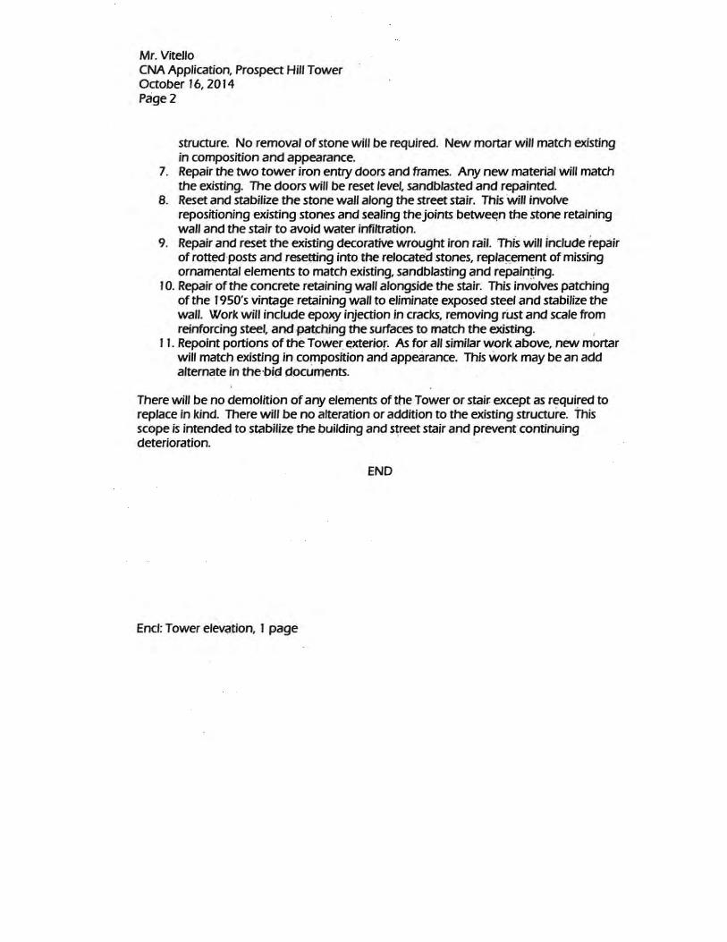
Mr. Vitello CNA Application, Prospect Hill Tower October 16, 2014 Page2
structure. No removal of stone will be required. New mortar will match existing in composition and appearance.
7. Repair the two tower iron entry doors and frames. Any new material will match the existing. The doors will be reset level, sandblasted and repainted.
8. Reset and stabilize the stone wall along the street stair. This will involve repositioning existing stones and sealing the joints betw~n the stone retaining wall and the stair to avoid water infiltration.
9. Repair and reset the existing decorative wrought iron rail. This will Include repair of rotted·posts and resetting into the relocated stones, replac:ement of missing ornamental elements to match existing, sandblasting and repain~ing.
1 0. Repair of the concrete retaining wall alongside the stair. This involves patching of the 1950's vintage retaining wall to eliminate exposed steel and stabilize the wall. Work will include epoxy injection in cracks, removing rust and scale from reinforcing steel, and pat(hing the surfaces to match the existing. ,
11. Repoint portions of the Tower. exterior. As for all similar w.ork above, new mortar will match existing in composition and appearance. This work may be an add alternate in the·pi~ documents.
There will be no demolition of any elements of the Tower or stair. except as required to replace in kind. There will be no alteration or addition to the existing structure. this scope is intended to stabilize the building and ~reet stair and prevent continuing deterioration.
END
Encl: Tower elev<ttion, 1 page

~ ~ :. ~ .. ~~~ ~
I I I I I I I I
I I I I I
I
I I I I I
I
I I I I I
I
I I I I
I I I I
I I I I
I I

DRAWING LISTCOVER SHEET
ARCHITECTURAL DRAWINGSA-1.0 PLANSA-2.0 TOWER ELEVATIONSA-3.0 STREET STAIR & RAIL ELEVATIONS & DETAILSA-4.0 TOWER SECTION
STRUCTURAL DRAWINGSS-1.1 GENERAL NOTES & ABBREVIATIONSS-1.1 STRUCTURAL PLANS & SECTIONS
NOVEMBER 14, 2014
CITY OF SOMERVILLE
SPRINKLERNEW - NEW HEADREL - RELOCATE
GRAPHIC SYMBOLS
NOTE
BREAK LINE
ELEVATION MARKER
REVISION NUMBER
SECTION MARKER
DETAIL MARKER
X
XA-X
XX
C-C/A3.0
DOOR NUMBERX
X
XA-X XX INTERIOR ELEVATION
LIGHT FIXTURE
NAME ## occ
ROOM NAME/ NUMBEROCCUPANCY @ 1:20 SF
FIBERGLASS INSULATION
RIGID INSULATION
MATERIAL INDICATIONS
WOOD BLOCKING
CONTINUOUS WOOD
FINISHED WOOD
CONCRETE
STEEL
PLYWOOD
BRICK
CONCRETE BLOCK
PROSPECT HILL TOWER STABILIZATIONSOMERVILLE, MASSACHUSETTS
EQ EQUALEX/EXIST EXISTINGFIN FINISHFL FLOORFLASH FLASHINGGA GAUGEGALV GALVANIZEDGC GENERAL CONTRACTORGL GLASS, GLAZINGGWB GYPSUM WALL BOARDH HIGH, HEIGHTHORIZ HORIZONTALIN INCHESINSUL INSULATIONLF LINEAR FOOTMAX MAXIMUMMECH MECHANICALMIN MINIMALMISC MISCELLANEOUSMO MASONRY OPENINGMO MAIN OFFICEMTL METALMUL MULLIONN NORTHNO NUMBERNOM NOMINALNTS NOT TO SCALEOC ON CENTEROPER OPERABLEOPNG OPENING
O.S.C.I. OWNER SUPPLIED CONTRACTOR INSTALLED
P PAINTPTD PAINTEDPLYWD PLYWOODQR QUARTER ROUNDQUAN QUANTITYREF REFERENCEREINF REINFORCEDREQD REQUIREDREV REVISEDRO ROUGH OPENINGS SOUTHSECT SECTIONSF SQUARE FOOTSHT SHEETSIM SIMILARSPEC SPECIFICATIONSQ SQUARESQIN SQUARE INCHSS STAINLESS STEELSTD STANDARDSTL STEELTHK THICKTYP TYPICALVERT VERTICALW WIDE, WESTW/ WITHWD WOODWT WEIGHT
ADD ADDITION, ADDENDUMALT ALTERNATE ALUM ALUMINUMAPPROX APPROXIMATE& AND@ ATBLDG BUILDINGBLKG BLOCKINGBRK BRICKCB CATCH BASINCL CENTER LINECLKG CAULKINGCLR CLEARCO CENTRAL OFFICECONC CONCRETECONST CONSTRUCTIONCONT CONTINUOUS CONTR CONTRACTORD DEEP, DEPTHDBL DOUBLEDEMO DEMOLITIONDET DETAILDIA DIAMETERDIM DIMENSIONDIV DIVISIONDS DOWN SPOUTDWG DRAWINGE EASTEA EACHEL ELEVATION
ARCHITECTURAL ABBREVIATIONSBUILDING CODE SUMMARYAll work shall comply completely with the Massachusetts State Building, 780 CMR, Eighth Edition, as ammended & 521 CMR MAAB. All work classified as repairs per Section 402. 402.1 Scope . Repairs, as defined in Chapter 2, include the patching or restoration or replacement of damaged materials, elements, equipment or fixtures for the purpose of maintaining such components in good or sound condition with respect to existing loads or performance requirements.
EXISTING CONDITIONSThese drawings have been compiled from the best available information and are not intended to limit the scope of work. All investigation was done by visual or best available documents provided by the City of Somerville. Any conditions to the contrary or not explicitly stated herein shall be considered latent and architect must be notified prior to any work not as outlined in these documents. It will be assumed that the contractor has inspected the site prior to construction and verified the information herein supplied.
All directions stated throughout documents are by Project North.
GENERAL NOTESThe General Contractor shall be responsible for all construction means, methods, co-ordination of other trades and techniques to produce a sound quality building. All dimensions, elevations and conditions must be verified by the General Contractor or responsible trade.* Apply for, obtain and pay for all required permits. Submit copies of permits to City of Somerville within 3 days of receipt and prior to commencing work.* Request schedule and attend all inspections required by the authorities having jurisdiction.
SET #
GENERAL INFO LOCI MAP
TBA PROJECT #: 1210.1
JOSEPH A. CURTATONE, MAYOR

5'-6"
A/A-
4.0
A-2.0A
A-2.0B
A-2.0D
A-2.0E
A-2.0C
A-2.0F
A/A-
4.0
A-2.0A
A-2.0B
A-2.0D
A-2.0E
A-2.0C
A-2.0F
REMOVE & REPLACE OVERHEAD STEEL SUPPORT FOR UPPER SLAB. SEE SHEET A-4.0
M2
A/A-
4.0
A-2.0A
A-2.0B
A-2.0D
A-2.0E
A-2.0C
A-2.0F
6'-0 1
1/16"
5'-4"
9'-1 1/16"
8'-10 5/8"
9'-0 3/8"
8'-10"
8'-11
15/16
"
DEMOLISH EXISTING CONCRETE SLAB AND REMOVE EXISTING STEEL I-BEAMS.
CUT EXISTING STEEL CIRCULAR STAIR SUPPORTS FROM I-BEAMS & STABILIZE STAIR IN PLACE FOR RECONNECTION TO NEW STEEL.
COORDINATE REMOVAL OF UPPER LEVEL STAIR RAIL FROM SLAB BY WROUGHT IRON SUBCONTRACTOR,
INSTALL NEW SLAB SUPPORTSSEE DRAWING S-2
INSTALL NEW CHEMICAL ANCHORS BETWEEN EXISTING GRANITEWALLS AND NEW SLAB PER DETAIL,SEE DRAWING S-2, ENTIRE SLAB PERIMETER.
INSTALL NEW SLAB PER DETAILS.SEE DRAWNG S-2.M2
PITCH TO DRAIN
NEW FLOOR DRAIN CAST INTO SLAB FLUSHTO DELIVER TO 4" STACK BELOW. EXTEND NEW PIPE +/- 27" TO EXISTING INTACT C.I RISER
A/A-
4.0
A-2.0A
A-2.0B
A-2.0D
A-2.0E
A-2.0C
A-2.0F
M2
LEVEL ONE SCALE 1/8"=1'-0" LEVEL TWO SCALE 3/16"=1'-0"
LEVEL THREE SCALE 3/16"=1'-0" LEVEL FOUR SCALE 3/16"=1'-0"
Date
: 11/1
7/14
File
nam
e: P
rosp
ect H
ill To
wer P
lans.v
wx
DATE OF ISSUE
SCALE
TBA PROJECT #
REVISIONS
DRAWN BY CHECKED BY COPYRIGHT
PROSPECT HILL TOWER STABILIZATION
MUNROE STREETSOMERVILLE, MA
CLEINT: CITY OF SOMERVILLEJOSEPH CURTATONE, MAYOR
1210.1
NOVEMBER 14, 2014
CLIENT:
JSL RF 2014
PLANS
A-1.0SEE ENLARGED PLAN SHEET A-4.0
1 2
3 4
0 2 4 8
3/16" = 1'-0" ON ORIGINAL
0 2 4 8
CALLEDNORTH
KEY TO SCOPE NOTES:
M1: REMOVE, REBED & RESET STONES. ALL STONES TO BE REINSTALLED IN ORIGINAL LOCATION. WROUGHT IRON GRILLES TO BE REMOVED AND RESET WITH MORTAR INSTONE, IN ORIGINAL LOCATIONS.
M2: EPOXY INJECTION TO CRACK.
M3: REPOINT ALL EXTERIOR STONE SURFACES, ALL FACES OF TOWER WHERE STONES ARE NOT RESET. MORTAR TO MATCH EXISTING IN JOINT DIMENSION AND SURFACE FINISH (ALT. 2)
WI1: CUT EXISTING STEEL PIPE RAIL AT OR ABOVE EXISTING FLANGES. RAIL TO BE CUT AND REMOVED BY WROUGHT IRON RESTORATION SUBCONTRACTOR. CLEAN, GRIND TO CLEAN METAL, WELD, PRIME & PAINT TWO COATS. POST EXTENDERS OF SAME DIA TO BE INSET INTO GRANITE AFTER REBEDDING.
WI2: REMOVE
M: MASONRY SUBCONTRACTOR
WI: WROUGHT IRON SUBCONTRACTOR
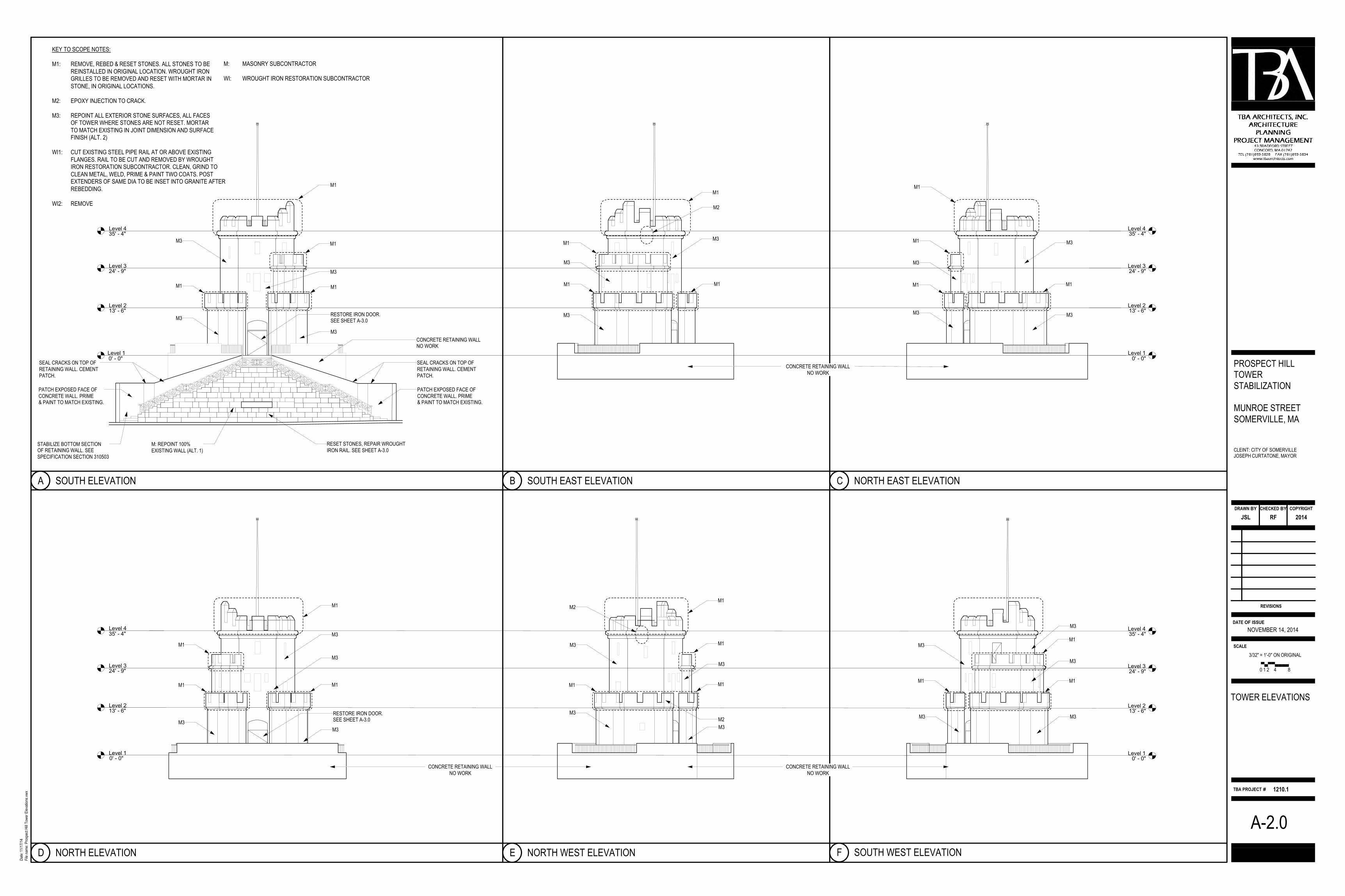
SOUTH ELEVATION SOUTH EAST ELEVATION
NORTH ELEVATION NORTH WEST ELEVATION
NORTH EAST ELEVATION
SOUTH WEST ELEVATION
Level 10' - 0"
Level 213' - 6"
Level 324' - 9"
Level 435' - 4"
Level 10' - 0"
Level 213' - 6"
Level 324' - 9"
Level 435' - 4"
Level 10' - 0"
Level 213' - 6"
Level 324' - 9"
Level 435' - 4"
Level 10' - 0"
Level 213' - 6"
Level 324' - 9"
Level 435' - 4"
RESTORE IRON DOOR.SEE SHEET A-3.0
M1
M1
M1M1
M3
M3
M3
M3
M: REPOINT 100% EXISTING WALL (ALT. 1)
RESET STONES, REPAIR WROUGHTIRON RAIL. SEE SHEET A-3.0
CONCRETE RETAINING WALLNO WORK
SEAL CRACKS ON TOP OF RETAINING WALL. CEMENT PATCH.
PATCH EXPOSED FACE OF CONCRETE WALL. PRIME& PAINT TO MATCH EXISTING.
STABILIZE BOTTOM SECTION OF RETAINING WALL. SEE SPECIFICATION SECTION 310503
SEAL CRACKS ON TOP OF RETAINING WALL. CEMENT PATCH.
PATCH EXPOSED FACE OF CONCRETE WALL. PRIME& PAINT TO MATCH EXISTING.
M1
M1M1
M1
M3
M3
M3
M2
M3
M1
M1
M3
M3
M1
M1
M3
CONCRETE RETAINING WALLNO WORK
CONCRETE RETAINING WALLNO WORK
CONCRETE RETAINING WALLNO WORK
RESTORE IRON DOOR.SEE SHEET A-3.0
M1
M1
M1 M1
M3
M3
M3
M3
M1
M1M1
M3
M3
M3M3
M3
M1
M1
M1
M2
M1
M3
M3
M3
M3
M2
A B C
D E F
Date
: 11/
17/1
4Fi
le na
me:
Pro
spec
t Hill
Towe
r Elev
ation
s.vwx
DATE OF ISSUE
SCALE
TBA PROJECT #
REVISIONS
DRAWN BY CHECKED BY COPYRIGHT
PROSPECT HILL TOWER STABILIZATION
MUNROE STREETSOMERVILLE, MA
CLEINT: CITY OF SOMERVILLEJOSEPH CURTATONE, MAYOR
1210.1
NOVEMBER 14, 2014
CLIENT:
JSL RF 2014
TOWER ELEVATIONS
A-2.0
KEY TO SCOPE NOTES:
M1: REMOVE, REBED & RESET STONES. ALL STONES TO BE REINSTALLED IN ORIGINAL LOCATION. WROUGHT IRON GRILLES TO BE REMOVED AND RESET WITH MORTAR INSTONE, IN ORIGINAL LOCATIONS.
M2: EPOXY INJECTION TO CRACK.
M3: REPOINT ALL EXTERIOR STONE SURFACES, ALL FACES OF TOWER WHERE STONES ARE NOT RESET. MORTAR TO MATCH EXISTING IN JOINT DIMENSION AND SURFACE FINISH (ALT. 2)
WI1: CUT EXISTING STEEL PIPE RAIL AT OR ABOVE EXISTING FLANGES. RAIL TO BE CUT AND REMOVED BY WROUGHT IRON RESTORATION SUBCONTRACTOR. CLEAN, GRIND TO CLEAN METAL, WELD, PRIME & PAINT TWO COATS. POST EXTENDERS OF SAME DIA TO BE INSET INTO GRANITE AFTER REBEDDING.
WI2: REMOVE
0 1 2 4 8
3/32" = 1'-0" ON ORIGINAL
KEY TO SCOPE NOTES:
M1 REMOVE, REBED & RESET STONES. ALL STONES TO BE REINSTALLED IN ORIGINAL LOCATION. WROUGHT IRON RAILS TO BE REPLACED IN EXISTING FLANGES. RESTORED RAIL TO BE REINSTALLED INTO GRANITE THROUGH EXISTING FLANGE IN ORIGINAL LOCATIONS.
M2 EPOXY INJECTION TO CRACK.
WI1 CUT EXISTING STEEL PIPE RAIL AT OR ABOVE EXISTING FLANGES. RAIL TO BE CUT AND REMOVED BY WROUGHT IRON RESTORATION SUBCONTRACTOR. CLEAN, GRIND TO CLEAN METAL & WELD NEW SLEEVE TO SECURE RAIL TO POST AND/OR CONTINUING RAIL. GRIND, WELD, SMOOTH, PRIME & PAINT TWO COATS.
M: MASONRY SUBCONTRACTOR
WI: WROUGHT IRON RESTORATION SUBCONTRACTOR

REMOVE SECTIONS?REMOVE SECTIONS? REMOVE SECTIONS?
NEW CHEMICAL ANCHORS THROUGH POST FLANGESINTO GRANITE. (TYP. EAST POST)SEE DETAIL 1.
13'-4" 2'-5" 16'-4 1/2" 8'-5" 16'-0" 2'-5" 13'-4"
72'-3 1/2"
LINEAR FEET OF RAIL:ALL DIMENSIONS APPROXIMATE
OVER ALL LENGTH OF RAIL
REMOVE RAIL SECTIONS TO SHOP FORREFINISHING. REINSTALL ON ADJUSTED POSTS AFTER GRANITE RESET (TYP.)
WI1
WI1
WI1
WI1 WI1
WI1
M3M3
PATCH CONCRETE RETAINING WALL
FRONT STAIRWAY RAILING SCALE 1"=1'-0"
FRONT STAIRWAY ELEVATION SCALE 1/4"=1'-0"
WI: NEW STEEL SURFACE MOUNTED BAR STOCK ORNAMENTAL PANELS. BAR STOCK 3/8"x1" TO MATCH ORIGINAL. PLUG WELD TO DOOR.
NOTE:
WI: REMOVE ALL REMAINING ORNAMENTAL PLATES, HINGES, AND OBSOLETE HARDWARE DEVICES. INSTALL NEW HANDLE AND HASPS FOR LOCKS, TOP AND BOTTOM. REPAIR AND RE HANG EXISTING 3/8" STEEL PLATE DOOR. PRIME & PAINT (3 COATS).
WI: NEW HINGES TO MATCH EXISTING, 3/8"x1" THICK WIDTH AND SHAPE TO MATCH EXISTING.BOLTS TO MATCH ORIGINAL IN APPEARANCE.
WI: NEW "C" SHAPE HANDLE. PAINTED TO MATCH DOOR.
1'-0" 1'-0" 1'-0"
5'-6"
4'-0"
1'-0 5
/8"2'-
0"2'-
1"1'-
5 1/2"
7'-0 1
/4"2'-
11 3/
4"
1'-3" 1'-3"
WI: NEW 3/8"x1" HASP TO FIX EXISTING FRAME.
CLEAN & SCRAPE EXISTING FRAME AND GRILLE. GRIND RUST TO BARE METAL. ABRAID ALL PAINT SURFACES, PRIME & PAINT (3 COATS).
WI: NEW 3/8"x1" HASP TO FIX EXISTING FRAME.
CLEAN & SCRAPE EXISTING FRAME AND GRILLE. GRIND RUST TO BARE METAL. ABRAID ALL PAINT SURFACES, PRIME & PAINT (3 COATS).
1'-1"
1'-0"
1'-6 1
/4"1'-
9 3/8"
M: FILL A CONTINUOUS MORTAR JOINT BETWEEN ALL GRANITE & CONCRETE STAIRS. VERTICAL & HORIZONTAL JOINTS TO BE CONTINUOUS.
EXISTING CONCRETESTAIRS TO REMAIN
CONTINUOUS MORTAR JOINTRUNNING ALONG TREAD & RISERS
NEW CHEMICAL ANCHORSINTO GRANITE IN TWOLOCATIONS, ALL POSTS INSET IN ORIGINAL FLANGES.
NOTE:
M: POSITION RAILING POSTS PLUMB AND ALIGN WITH ALL OTHER RAILING POSTS (TYP.)
M: WHERE STONES ARE TIGHT TO EXISTING CONCRETE, DIG OUT JOINT TO 2" MIN. DEPTH FOR CONTINUOUS MORTAR JOINT.
RESET GRANITE ASNOTED ON ELEVATIONS
MORTAR BACK BED TO STABILIZESOIL & BED TO CONTINUOUSCAULK JOINT
STABILIZE SOIL
WI: FABRICATE POST EXTENSIONTO MATCH EXISTING PIPE
WI: WELD POST TO FLANGE
M: MASON TO DRILL THROUGH FLANGE & INTO GRANITE 6" DEEP TO RECEIVE POST. COORDINATE FINAL LOCATION WITH WROUGHT IRON RESTORATION SUBCONTRACTOR.
M: PATCH HOLES FROM RAIL ELEMENTS
WI: REMOVE PRIOR REPAIRS. PATCH STEEL WHERE DAMAGED.
WHERE STONES ARE TIGHT TO EXISTING CONCRETE, DIG OUT JOINT TO 2" MIN. DEPTH FOR MORTAR JOINT
EXISTING STEEL FLANGE TO REMAIN
WI: POST PIPE TO BE SET INTO GRANITE WITH SETTING CEMENT
MASONRY DETAIL SCALE 1 1/2"=1'-0"
WI: CUT CONNECTIONS AT ORNAMENTAL FILIGREE TO ALLOW RAIL REMOVAL
WI: CUT PIPE RAILS TOP & BOTTOM WHERE A CONNECTIONS REMAINTO ALLOW REMOVAL FOR REPAIR & REFINISHING
WI: CUT PIPE RAILS TOP & BOTTOM WHERE A CONNECTIONS REMAINTO ALLOW REMOVAL FOR REPAIR & REFINISHING
FRONT ENTRY WAY SCALE 1/2"=1'-0"
7"
1'-8"
7"
7"
ORNAMENTAL PANELSALL 3/8"x1" BAR STOCK
CONTRACTOR TO VERIFY ALL DIMENSIONS IN FIELD.
KEY TO SCOPE NOTES:
M1 REMOVE, REBED & RESET STONES. ALL STONES TO BE REINSTALLED IN ORIGINAL LOCATION. WROUGHT IRON RAILS TO BE REPLACED IN EXISTING FLANGES. RESTORED RAIL TO BE REINSTALLED INTO GRANITE THROUGH EXISTING FLANGE IN ORIGINAL LOCATIONS.
M2 EPOXY INJECTION TO CRACK.
WI1 CUT EXISTING STEEL PIPE RAIL AT OR ABOVE EXISTING FLANGES. RAIL TO BE CUT AND REMOVED BY WROUGHT IRON RESTORATION SUBCONTRACTOR. CLEAN, GRIND TO CLEAN METAL & WELD NEW SLEEVE TO SECURE RAIL TO POST AND/OR CONTINUING RAIL. GRIND, WELD, SMOOTH, PRIME & PAINT TWO COATS.
M: MASONRY SUBCONTRACTOR
WI: WROUGHT IRON RESTORATION SUBCONTRACTOR
WI2
Date
: 11/
17/1
4Fi
le na
me:
Pro
spec
t Hill
Towe
r Elev
ation
s.vwx
DATE OF ISSUE
SCALE
TBA PROJECT #
REVISIONS
DRAWN BY CHECKED BY COPYRIGHT
PROSPECT HILL TOWER STABILIZATION
MUNROE STREETSOMERVILLE, MA
CLEINT: CITY OF SOMERVILLEJOSEPH CURTATONE, MAYOR
1210.1
NOVEMBER 14, 2014
CLIENT:
JSL RF 2014
STREET STAIR & RAIL ELEVATIONS & DETAILS
A-3.01 2 3
A
AS NOTED
0 1 2 4
0 1 2 4 8
0 1 20 1 2
KEY TO SCOPE NOTES:
M1: REMOVE, REBED & RESET STONES. ALL STONES TO BE REINSTALLED IN ORIGINAL LOCATION. WROUGHT IRON GRILLES TO BE REMOVED AND RESET WITH MORTAR INSTONE, IN ORIGINAL LOCATIONS.
M2: EPOXY INJECTION TO CRACK.
M3: REPOINT ALL EXTERIOR STONE SURFACES, ALL FACES OF TOWER WHERE STONES ARE NOT RESET. MORTAR TO MATCH EXISTING IN JOINT DIMENSION AND SURFACE FINISH (ALT. 2)
WI1: CUT EXISTING STEEL PIPE RAIL AT OR ABOVE EXISTING FLANGES. RAIL TO BE CUT AND REMOVED BY WROUGHT IRON RESTORATION SUBCONTRACTOR. CLEAN, GRIND TO CLEAN METAL, WELD, PRIME & PAINT TWO COATS. POST EXTENDERS OF SAME DIA TO BE INSET INTO GRANITE AFTER REBEDDING.
WI2: REMOVE

ILLUSTRATIVE TOWER SCALE 3/16"=1'-0"
Date
: 11/1
7/14
File
nam
e: P
rosp
ect H
ill To
wer P
lans.v
wx
DATE OF ISSUE
SCALE
TBA PROJECT #
REVISIONS
DRAWN BY CHECKED BY COPYRIGHT
PROSPECT HILL TOWER STABILIZATION
MUNROE STREETSOMERVILLE, MA
CLEINT: CITY OF SOMERVILLEJOSEPH CURTATONE, MAYOR
1210.1
NOVEMBER 14, 2014
CLIENT:
JSL RF 2014
TOWER SECTION
A-4.0
6"10
"
EXISTING CONCRETE SLAB, LOWER DECK
NEW CONCRETE SLAB, UPPER DECK
EXISTING 3 3/4" OD GALVANIZED STEEL PIPE 0.313 WALL THICKNESS A500/513 STEEL PIPE BUSHWICK METALS INC. OR EQUALS
1/2" S/S HILTI BOLT, 4 PER FLANGE INTO NEW DECK
CITY TO REINSTALL EXISTING FIBERGLASS POLE
REINSTALL EXISTING 12" X 12" X 1/2" GALVANIZED STEEL PLATE. EXISTING PIPE DIMENSION, SEE DETAIL TO LEFT.
REUSE EXISTING THREADED STAINLESS STEEL ROD, PASS THROUGH EXISTING HOLES IN FLAGPOLE WHEN FLAGPOLE IS REINSTALLED
NEW NEOPRENE GASKET ON BOTH SIDES
EXISTING 1/2" S/S HILTI BOLT, 4 PER FLANGE
EXISTING 12" X 12" X 1/2" GALVANIZED STEEL PLATE SITTING UNDER EXISTING PIPE
MODIFY PLATE TO FIT STAIR AND RAIL AS REQUIRED
MODIFY PLATE TO FIT STAIR AND RAIL AS REQUIRED
CONTINUOUS WELD BETWEEN PLATE AND PIPE SLEEVE AND BETWEEN PLATE SECTIONS
WHERE BOLT SITS ABOVE I BEAM, WELD 1/2" THREADED ROD TO TOP OF I BEAM. PATCH CONCRETE. SECURE WITH GALVANIZED WASHER & NUT.
NEW EPDM BOOT OVER GALVANIZED PLATE GLUED TO FLAGPOLE & DECK
12'-0
" GAL
VANI
ZED
STEE
L PIP
E
8"
REUSE EXISTING 12" X 12" X 1/2" GALVANIZED STEEL PLATE
NOTE:
UPPER DECK PLATE TO BE WELDED TO NEW SLEEVE PIPE.
CITY TO REMOVE FLAGPOLE TO ACCOMODATE WORK.
CONTRACTOR TO REMOVE ALL FLAGPOLE ATTACHMENT DEVICES AND REINSTALL IN NEW WORK.
NEW __" GALVANIZED STEEL SLEEVE PLACED IN NEW SLAB FLAGPOLE SUPPORT.
EXISTING BASE PLATE
EXISTING BALUSTER & RAIL
CUT RAIL
REMOVE FOR RESTORATION. REINSTALL & RECONNECT RAIL AT BASE, GRIND SMOOTH, PAINT & PRIME
Level 1
0' - 0"
Level 2
13' - 6"
Level 3
24' - 9"
Level 4
35' - 4"
WI: RESTORED RAIL TO BE FIELD WELDED ON REINSTALLATION. GRIND SMOOTH, PRIME & PAINT (3 COATS).
STEEL & STAIR SUPPORT BETWEEN WFSTRUCTURE & UNDERSIDE OF STAIR PLATFORM
WI: EXISTING SPIRAL STAIR & RAIL (15 RISERS) TO REMAIN IN PLACE. MECHANICALLY SCRAPE & GRIND TO REMOVE LOOSE & FLAKING PAINT, ELIMINATE ALL RUST, PRIME & PAINT
WI: REMOVE EXISTING RAIL. SANDBLAST TO BARE METAL. PRIME & PAINT
REMOVE & REINSTALL RAIL BASE PLATE ON NEW SLAB.
EXISTING PLATE, STEEL STAIRS, POSTS & RAIL TO BE SCRAPED, PRIMED & PAINTED.
EXISTING C.I FLOOR DRAIN STACK
APPROACH STAIR & RAILNO WORK
RESECURE EXISTING RAILING TO STONE WALL. RESTORE STRUCTURAL INTEGRITY TO RAIL. SCRAPE OR GRIND TO BARE METALAT REPAIR. REMOVE LOOSE & FLAKING PAINT,ABRADE TO RECEIVE NEW PAINT. PRIME & PAINT RAIL AND STAIR
WF
1'-6"
NEW C.I FLOOR DRAIN & 4" STACK SECTION, NESTED INTO EXISTING C.I STACK APPROX. 27 INCHES FROM BOTTOM OF SLAB.
M2
RESTORE STRUCTURAL INTEGRITY TO RAILING (ROUND TO PLATE)
WI: EXISTING SPIRAL STAIR & RAIL (14 RISERS) TO REMAIN IN PLACE. MECHANICALLY SCRAPE & GRIND TO REMOVE LOOSE & FLAKING PAINT, ELIMINATE ALL RUST, PRIME & PAINT
FLAGPOLE AXON DETAIL
LEVEL FOUR ENLARGED PLAN SCALE 1/2"=1'-0"
NOTE:
UPPER DECK PLATE TO BE WELDED TO NEW SLEEVE PIPE.
CITY TO REMOVE FLAGPOLE TO ACCOMODATE WORK.
CONTRACTOR TO REMOVE ALL FLAGPOLE ATTACHMENT DEVICES AND REINSTALL IN NEW WORK.
GENERAL NOTES:
1. CONTRACTOR TO VERIFY ALL DIMENSIONS.2. GRIND WHERE GALVANIZED FOR WELD.3. EXPOSED STEEL & FILLET WITH ZRC.4. EPOXY ANCHORS IN TO CONCRETE
FLAGPOLE SECTION DETAIL
5'-4"
REMOVE & REPLACE EXISTING STEEL STAIR SUPPORT WELDED TO WEB OF NEW STEEL WF CONNECTED TO UNDERSIDE OF STAIR PLATFORM. PRIME & PAINT.
EXISTING TOP RAIL, BALUSTERS & BASE PLATE TO BE CUT FROM STAIR RAIL & PLATFORM, REMOVED BY WI SUBCONTRACTOR, SANDBLASTED, REFINISHED & REINSTALLED AFTER CONCRETE DECK IS REPLACED
EDGE OF CONCRETE SLAB 52" DIAMETER. CONTRACTOR TO VERIFY IN FIELD.
EXISTING FLAGPOLE AND SUPPORTS REMOVED AND REPLACED IN SAME LOCATION. SEE SHEET A-4.0 DETAILS 5 & 6.
M2 M2
A/A-
4.0
CUT RAIL
A 4
CUT RAIL
AS NOTED
0 2 4 8 0 1 2 4
5 6
KEY TO SCOPE NOTES:
M1: REMOVE, REBED & RESET STONES. ALL STONES TO BE REINSTALLED IN ORIGINAL LOCATION. WROUGHT IRON GRILLES TO BE REMOVED AND RESET WITH MORTAR INSTONE, IN ORIGINAL LOCATIONS.
M2: EPOXY INJECTION TO CRACK.
M3: REPOINT ALL EXTERIOR STONE SURFACES, ALL FACES OF TOWER WHERE STONES ARE NOT RESET. MORTAR TO MATCH EXISTING IN JOINT DIMENSION AND SURFACE FINISH (ALT. 2)
WI1: CUT EXISTING STEEL PIPE RAIL AT OR ABOVE EXISTING FLANGES. RAIL TO BE CUT AND REMOVED BY WROUGHT IRON RESTORATION SUBCONTRACTOR. CLEAN, GRIND TO CLEAN METAL, WELD, PRIME & PAINT TWO COATS. POST EXTENDERS OF SAME DIA TO BE INSET INTO GRANITE AFTER REBEDDING.
WI2: REMOVE
M: MASONRY SUBCONTRACTOR
WI: WROUGHT IRON SUBCONTRACTOR

GENERAL
1. Structural work shall conform to the requirements of the Commonwealth ofMassachusetts State Building Code, 8th Edition, 2009 International BuildingCode w/Massachusetts Amendments, 2009 International Existing BuildingCode w/Massachusetts Amendments.
2. Examine architectural, mechanical, plumbing and electrical drawings forverification of location and dimensions of chases, inserts, openings, sleeves,washes, drips, reveals depressions and other project requirements not shown onstructural drawings.
3. Contractor shall verify and coordinate all dimensions on the project.4. Openings in slabs or walls less than 12 inches in diameter are generally not
shown. Openings shown on structural drawings shall not be revised withoutwritten approval from the engineer.
5. Openings in slabs, walls and roof deck in addition to those shown on thestructural drawings shall be incorporated into the work as required by thearchitectural contract documents.
6. Details not specifically shown shall be similar to those shown for the mostnearly similar situation as determined by the engineer.
7. unless noted elsewhere in the contract documents, requirements noted belowshall apply.
CONCRETE
1. Concrete work shall conform to ACI 318-08 "Building Code Requirements forStructural Concrete and ACI 301-08 "Specifications for Structural Concrete forBuildings.
2. Concrete shall be controlled concrete, proportioned, mixed and placed underthe supervision of an approved testing agency.
3. Concrete shall have the following minimum compressive strength at 28 days:(A) all concrete .................................................. 4000 psi
4. Concrete shall have the following nominal dry density:(a) normal weight................... 145 pcf
5. Concrete to be exposed to weather in the finished project shall be air-entrained.6. The use of construction joints where shown on the drawings is mandatory.
Omissions, additions or changes shall not be made except with the submissionof a written request together with drawings of the proposed joint locations forapproval by the architect.
7. Where construction joints are not shown, drawings showing location ofconstruction joints and concrete placing sequence shall be submitted to theengineer for approval prior to preparation of the reinforcement shop drawings.
8. Concrete slabs, including slabs on steel deck, shall be cast so that the slabthickness is at no point less than that indicated on the drawings.
9. Concrete shall be placed without horizontal construction joints except whereshown or noted.
REINFORCEMENT
1. Detailing, fabrication and erection of reinforcement shall conform to ACI 318-08"Building Code Requirements for Structural Concrete" and ACI 315-05 "Manual ofStandard Practice for Detailing Reinforced Concrete Structures".
2. Steel reinforcement shall conform to ASTM 615 Grade 60 (yield stress = 60,000psi)
3. Welded wire fabric reinforcement shall conform to ASTM 1854. Provide and schedule on shop drawings all necessary accessories to hold
reinforcement securely in position. minimum requirements shall be: high chairs,3'-0" on center; #5 support bar on high chairs; slab bolsters, 3'-0" on center.
5. Minimum concrete cover for reinforcement unless otherwise noted shall be asfollows:
Unformed surfaces in contact with ground or exposed to weather (footings,slabs on grade) 3"
Formed surfaces in contact with ground or exposed to weather. 2"Interior slabs 1.5"
STRUCTURAL STEEL
1. Structural steel work shall conform to 2010 AISC "Specification for StructuralSteel buildings", 2010 AISC "Code of Standard Practice for Steel Buildings andBridges" and 2010 AWS D1.1 "Structural Welding Code - Steel".
2. Structural steel shall be detailed in accordance with the AISC "Detailing for SteelConstruction" (AISC-2009) and designed in accordance with references notedabove.
3. Structural steel shall be new steel conforming to the following:(a) Unless otherwise noted ASTM A992 Grade 50 (Fy = 50 KSI)(b) Angles, channels, Tee, etc. ASTM A36 Grade 36 (Fy = 36 KSI)(c) Tubes ASTM A500 Grade B (Fy = 46 KSI)(d) Pipes ASTM A501 Type or S, Grade B or
ASTM A53(e) Anchor Bolts ASTM F1554 Grade 50(f) High strength bolts ASTM A325
4. Bolted connections shall be as follows:a) Minimum bolt diameter -3/4", two bolts minimum.b) Standard, oversized or horizontal short slotted holes in webs of beams.c) Simple shear connections shall be capable of end rotation per AISC requirements
for "Unrestrained Members"5. Welded connections shall be made by approved certified welders using filler metal
conforming to E70XX or F7X-EXXX with low hydrogen.6. Welds shall develop full strength of the materials being welded unless otherwise
noted.7. Welding shall conform to the American Welding Society code (AWS). All fillet
welds shall be made with a return leg on the weld end. The minimum size of filletwelds shall be determined in accordance with the AISC specifications for structuralsteel buildings. Provide backing bars and or spacers as required for satisfactorywelding.
8. Anchor bolts, leveling plates, or bearing plates shall be located and built intoconnecting work, preset by templates or similar methods. plates shall be set in fullbeds of non-shrink grout. wet setting shall not be allowed.
9. All steel exposed to weather shall be hot dipped galvanized.10. Structural steel details not specifically shown shall be similar to those shown for
most nearly similar situations as determined by the engineer.11. Field cutting of structural steel or any field modifications to structural steel shall
not be made without approval by the engineer for each specific case.12. Structural steel framing shall be true and plumb before connections are finally
bolted or welded.13. Temporary erection bracing and supports shall be provided to hold structural steel
framing securely in position. such temporary bracing and supports shall not beremoved until permanent bracing has been installed and floor slabs have attained75 percent of specified concrete strength.
ABBREVIATIONS
ABBREVIATION WORD
ASD ALLOWABLE STRESS DESIGN
ALT ALTERNATE
AASHTO AMERICAN ASSOCIATION OF STATE HIGHWAY
& TRANSPORTATION OFFICIALS
ACI AMERICAN CONCRETE INSTITUTE
AIA AMERICAN INSTITUTE OF ARCHITECTS
AISC AMERICAN INSTITUTE OF STEEL
CONSTRUCTION
AITC AMERICAN INSTITUTE OF TIMBER
CONSTRUCTION
ARCH ARCHITECTURAL
ASCE AMERICAN SOCIETY OF CIVIL ENGINEERS
ASTM AMERICAN SOCIETY FOR TESTING MATERIALS
AWS AMERICAN WELDING SOCIETY
AB ANCHOR BOLT
@ AT RATE OF
BAL BALANCE
BM BEAM
BRG BEARING
BLK BLOCK
B OR BOT BOTTOM
BEW BOTTOM EACH WAY
BRKT BRACKET
BLDG BUILDING
CIP CAST-IN-PLACE
CG CENTER OF GRAVITY
CTRD CENTERED
CO CLEAN OUT
C CENTERLINE
CLR CLEAR
COL COLUMN
CONC CONCRETE
CMU CONCRETE MASONRY UNIT
CRSI CONCRETE REINFORCING STEEL INST.
CONN CONNECTION
CONST CONSTRUCTION
CONST JT OR C CONSTRUCTION JOINT
CONT CONTINUOUS
CJ CONTROL JOINTS
DEPR DEPRESSION
DET DETAIL
DL DEVELOPMENT LENGTH
DIA OR Ø DIAMETER
DIM DIMENSION
DIR DIRECTION
DO DITTO
DWLS DOWELS
DN DOWN
DWG DRAWING
EA EACH
EE EACH END
EF EACH FACE
ES EACH SIDE
EW EACH WAY
EL ELEVATION
ELEV ELEVATOR
EC EPOXY COATED
EQ EQUAL
EXP BOLT EXPANSION BOLT
EXP JT EXPANSION JOINT
EXT EXTERIOR
FF FAR FACE
FT FEET OR FOOT
FIN FINISH
FIN FL FINISHED FLOOR
FPRF FIREPROOF
FL FLOOR
FD FLOOR DRAIN
FTG FOOTING
FND FOUNDATION
GALV GALVANIZED
GA GAGE OR GAUGE
GR GRADE
GB GRADE BEAM
HT HEIGHT
HP HIGH POINT
HS HIGH STRENGTH
H OR HORIZ HORIZONTAL
HEF HORIZONTAL EACH FACE
HIF HORIZONTAL INSIDE FACE
HOF HORIZONTAL OUTSIDE FACE
IN INCH
INCL INCLUSIVE OR INCLUDING
INFO INFO
ID INSIDE DIAMETER
INSUL INSULATION
IBC INTERNATIONAL BUILDING CODE
INV INVERT
JT JOINT
K KIP (1000 POUNDS)
LE LEFT END
LW LIGHTWEIGHT
LWC LIGHTWEIGHT CONC
LRFD LOAD & RESISTANCE FACTOR DESIGN
LOC LOCATION
LLV LONG LEG VERTICAL
LP LOW POINT
LL LOWER LAYER
MFR MANUFACTURER
MAS MASONRY
MATL MATERIAL
MECH MECHANICAL
MEP MECHANICAL, ELECTRICAL, PLUMBING
MEZZ MEZZANINE
MID MIDDLE
MID-PT MIDPOINT
NFoPA NATIONAL FOREST PRODUCTS ASSOCIATION
NF NEAR FACE
NWC NORMALWEIGHT CONCRETE
NIC NOT IN CONTRACT
NTS NOT TO SCALE
NO OR # NUMBER
OSHA OCCUPATIONAL SAFETY & HEALTH
ADMINISTRATION
OC ON CENTER
OPNG OPENING
OH OPPOSITE HAND
OD OUTSIDE DIAMETER
PC PILE CAP
PL PLATE
PT POINT
PVC POLYVYNYL CHLORIDE
PCA PORTLAND CEMENT ASSOCIATION
P/T POST TENSIONED
PSF POUNDS PER SQUARE FOOT
PSI POUNDS PER SQUARE INCH
P/C PRECAST CONCRETE
PCI PRECAST CONCRETE INSTITUTE
PTW PRESSURE TREATED WOOD
P/S PRESTRESSED
R RADIUS
REF REFERENCE
REINF REINFORCE or REINFORCEMENT/ING
REM REMAINDER
RETG RETAINING
RET RETURN
RE RIGHT END
RD ROOF DRAIN
SECT SECTION
SC SHEAR CONNECTOR
SHT SHEET
SLV SHORT LEG VERTICAL
SIM SIMILAR
SOG SLAB ON GRADE
SPA SPACES
SPECS SPECIFICATIONS
SL SPLICE LENGTH
SQ SQUARE
SS STAINLESS STEEL
STD STANDARD
STL STEEL
SDI STEEL DECK INSTITUTE
SJI STEEL JOIST INSTITUTE
SF STEP FOOTING
STIFF STIFFENER
STR STRUCTURAL
SP SUMP PIT
SUP SUPPORT
SYM SYMMETRICAL
TEMP TEMPERATURE
THK THICK OR THICKNESS
THRD THREADED
TB TIE BEAM
TIM TIMBER
T TOP
T&B TOP & BOTTOM
TOC TOP OF CONCRETE
TOS TOP OF STEEL
TOW TOP OF WALL
TYP TYPICAL
UNO UNLESS NOTED OTHERWISE
UL UPPER LAYER
U.L. UNDERWRITERS LABORATORIES
V OR VERT VERTICAL
VEF VERTICAL EACH FACE
VIF VERTICAL INSIDE FACE
VOF VERTICAL OUTSIDE FACE
WPG WATERPROOFING
WWF WELDED WIRE FABRIC
WWPA WESTERN WOOD PRODUCTS ASSOCIATION
W/ WITH
WP WORKING POINT
WS WATERSTOP
DESIGN LOADS
Loads shall conform to the requirements of the Massachusetts State Building Code, 8thEdition W/Amendments to IBC 2009
1. Floor live loads
Floors 100 psf
2. Roof live loads
Observation Deck 100 psf
3. Wind loads
Basic wind speed (three-second gust): v = 110 mphImportance factor: (Iw) = 1.0Occupancy category: IIIWind exposure category: b
4. Seismic
Importance factor: I = 1.0, Occupancy category IIIMapped spectral response accelerations: Ss = 0.29, S 1 = 0.068Site class: ????Spectral response coefficients: SDS = 0.40Seismic design category: DBasic seismic force resisting system: Ordinary plain masonry shear walls.Response modification factor: R = 1.5Analysis procedure: Per Appendix A1, Section A110 - IEBC
TBA ARCHITECTS, INC.ARCHITECTURE
PLANNINGPROJECT MANAGEMENT
43 BRADFORD STREETCONCORD, MA 01742
TEL (781)893-5828 FAX (781)893-5834www.tbaarchitects.com
DATE OF ISSUE
SCALE
NOT FOR CONSTRUCTION
TBA PROJECT #
REVISIONS
DRAWN BY CHECKED BY COPYRIGHT
PROSPECT HILLTOWERSTABILIZATION
MUNROE STREETSOMERVILLE, MA
CLEINT: CITY OF SOMERVILLEJOSEPH CURTATONE, MAYOR
1210.1
NOVEMBER 14, 2014
CLIENT:
2014DB RWM
NONE
GENERAL NOTES& ABBREVIATIONS
S-1.0

TBA ARCHITECTS, INC.ARCHITECTURE
PLANNINGPROJECT MANAGEMENT
43 BRADFORD STREETCONCORD, MA 01742
TEL (781)893-5828 FAX (781)893-5834www.tbaarchitects.com
DATE OF ISSUE
SCALE
NOT FOR CONSTRUCTION
TBA PROJECT #
REVISIONS
DRAWN BY CHECKED BY COPYRIGHT
PROSPECT HILLTOWERSTABILIZATION
MUNROE STREETSOMERVILLE, MA
CLEINT: CITY OF SOMERVILLEJOSEPH CURTATONE, MAYOR
1210.1
NOVEMBER 14, 2014
CLIENT:
2014DB RWM
AS NOTED
LEVEL FOUR PLANAND SECTIONS
S-2.0