cinemática inversa 6-rus
TRANSCRIPT
22nd International Congress of Mechanical Engineering (COBEM 2013)November 3-7, 2013, Ribeirão Preto, SP, Brazil
Copyright c© 2013 by ABCM
INVERSE KINEMATICS FOR GENERAL 6-RUS PARALLEL ROBOTSAPPLIED ON UDESC-CEART FLIGHT SIMULATOR
Alexandre CamposGuilherme de FaveriClodoaldo Schutel Furtado NetoUniversidade do Estado de Santa Catarina (UDESC), Centro de Ciências Tecnológicas (CCT), Joinville, [email protected]@[email protected]
Alexandre ReisAlejandro GarciaUniversidade do Estado de Santa Catarina (UDESC), Centro de Artes (CEART), Florianópolis, [email protected]@gmail.comAbstract. Abstract. The growth of brazilian aviation industry led to implementation of new manufacturing plants as wellas equipment aiming at provide training for pilots. Manufacturing plants will be located in Lages -SC, additionally theUniversidade do Estado de Santa Catarina built a flight simulator based on 6-DoF parallel robot which incorporatesvirtual reality immersion environment. Parallel robots are closed-loop mechanisms presenting very good performancesin terms of accuracy, rigidity and ability to manipulate large loads. This paper states a method to compute the inversekinematics for a generic 6-RUS parallel robot (i.e. 6 serial chains with Rotational, Universal and Spherical joints respec-tively) based in geometrical constructive aspects. This method manipulates algebraically closed loop equations which ledto univocal solution with low computational cost. Additionally, the method is useful tool to compute the flight simulatorwork space for different orientations.
Keywords:Parallel Robot, Flight Simulator, Inverse Kinematic Problem.
1. INTRODUCTION
Flight simulation has been used in flying industry for many years. Due to the aircraft and pilots training costs, develop-ment of many flying training devices became necessary, thus in the decade 1960 use of flight simulator became an integralpart of all commercial airline operation and for both safety and training effectiveness, it became no longer practical totrain in the actual aircraft (Page, 2010).
Early flight simulators were attempted to achieve the early training effects that was based in graded exercises sequencewhIch are realized by the pilot in real aircraft. So the first trainers were ground-based devices able to react to aerodynamicforces, like Sanders Teacher device developed in 1910 (Page, 2010).
Graphic computing progress led flight simulation into virtual reality, but only simulation in virtual environment doesnot expose pilot to real forces during flight, which cause nausea and discomfort after some hours due to sensorial dis-connection between sight and space perception detected by vestibular system, located in inner ear (Carlos S.M. Coelho,2007).
Other devices used as flight simulators include 3 DoF or 6DoF parallel robots. The spatial parallel robot (6 DoF)are convenient due to full motion possibility. The most used 6 DoF platform is Stewart-Gough platform which is basedin 6-UPS (i.e. 6 serial chains with Universal - Prismatic - Spherical joints respectively), that was developed to be usedas a full flight simulator. Second most common parallel robot architecture used for flight simulation is 6-RUS, which isapproached in this paper.
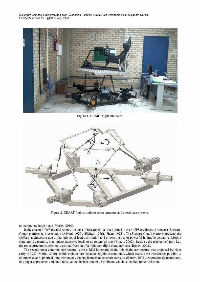
In Fig. 1 is presented CEART flight simulator and in Fig. 2 the parallel robot structure and the cordinates systemsattached to fixed base fO and to move platform mO.
2. PARALLEL ROBOTS
Parallel robots, also named parallel manipulators, typically consist by a moving platform connected to a fixed base byseveral limbs or legs (Merlet, 2010).
An n-DOF (n-degree-of-freedom) fully-parallel mechanism is composed of n independent legs connecting the mobileplatform to the base. Each of these legs is a serial kinematic chain that hosts one or more motors which actuates, directlyor indirectly, the chain (Bonev, 2002).
Due to distribution of external load, parallel robots present good performances in terms of accuracy, rigidity and ability
Alexandre Campos, Guilherme de Faveri, Clodoaldo Schutel Furtado Neto, Alexandre Reis, Alejandro GarciaInverse Kinematic for 6-RUS parallel robot
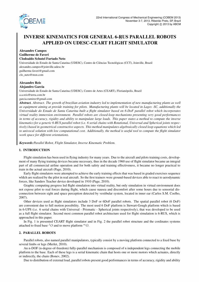
Figure 1. CEART flight simulator.
Figure 2. CEART flight simulator robot structure and coordinate systems.
to manipulate large loads (Merlet, 2010).In the area of 6-DoF parallel robots, the most of researches has been aimed to the 6-UPS architecture known as Stewart-
Gough platform as presented in (Advani, 1998), (Fichter, 1986), (Haan, 1995) . The Stewart-Gough platform presents thestiffness architecture due to the only axial load distribution and allows the use of powerful hydraulic actuators. Motionsimulators, generally, manipulate excessive loads of up to tens of tons (Bonev, 2002). Besides, the mechanical part, i.e.,the robot structure is often only a small fraction of a high-tech flight simulator cost (Bonev, 2002).
The second most common architecture is the 6-RUS kinematic chain, this chain architecture was proposed by Huntearly in 1983 (Merlet, 2010). In this architecture the actuated joint is rotational, which leads to the interchange possibilityof universal and spherical joint without any change in mechanism characteristics (Bonev, 2002). As previously mentioned,this paper approaches a method to solve the inverse kinematic problem, which is detailed in next session.
22nd International Congress of Mechanical Engineering (COBEM 2013)November 3-7, 2013, Ribeirão Preto, SP, Brazil
3. INVERSE KINEMATIC PROBLEM
For inverse kinematic problem the vector describing moving platform position in cartesian coordinates system andorientation by roll, pitch and yaw angles respectively is given by P = [Px Py Pz ϕ ϑ ψ].
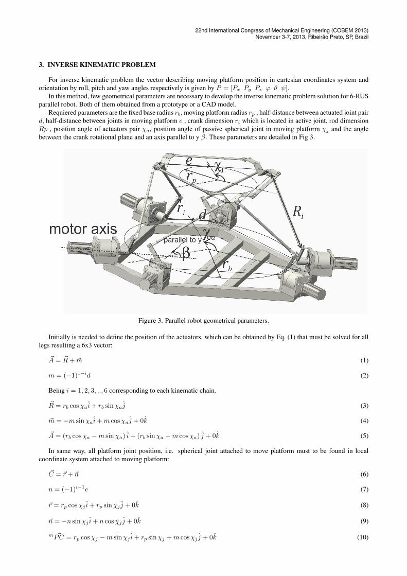
In this method, few geometrical parameters are necessary to develop the inverse kinematic problem solution for 6-RUSparallel robot. Both of them obtained from a prototype or a CAD model.
Requiered parameters are the fixed base radius rb, moving platform radius rp , half-distance between actuated joint paird, half-distance between joints in moving platform e , crank dimension ri which is located in active joint, rod dimensionRp , position angle of actuators pair χa, position angle of passive spherical joint in moving platform χj and the anglebetween the crank rotational plane and an axis parallel to y β. These parameters are detailed in Fig 3.
Figure 3. Parallel robot geometrical parameters.
Initially is needed to define the position of the actuators, which can be obtained by Eq. (1) that must be solved for alllegs resulting a 6x3 vector:
~A = ~R+ ~m (1)
m = (−1)1−id (2)
Being i = 1, 2, 3, .., 6 corresponding to each kinematic chain.
~R = rb cosχai+ rb sinχaj (3)
~m = −m sinχai+m cosχaj + 0k (4)
~A = (rb cosχa −m sinχa) i+ (rb sinχa +m cosχa) j + 0k (5)
In same way, all platform joint position, i.e. spherical joint attached to move platform must to be found in localcoordinate system attached to moving platform:
~C = ~r + ~n (6)
n = (−1)i−1e (7)
~r = rp cosχj i+ rp sinχj j + 0k (8)
~n = −n sinχj i+ n cosχj j + 0k (9)
m ~PC = rp cosχj −m sinχj i+ rp sinχj +m cosχj j + 0k (10)
Alexandre Campos, Guilherme de Faveri, Clodoaldo Schutel Furtado Neto, Alexandre Reis, Alejandro GarciaInverse Kinematic for 6-RUS parallel robot
The rotational transformation using roll, pitch and yaw angles notation as defined in (Bruno Siciliano, 2009) is used inorder to find m ~PC from Tool Center Point, attached to move platform origin mO to spherical joint in general coordinatesystem attached to fixed base origin f ~O.
rot =
cϕcθ cϕsϑsψ − sϕcψ cϕsϑcψ + sϕcψsϕcθ sϕsϑsψ + sϕcψ sϕsϑcψ − cϕsψ−sϑ cϑsψ cϑcψ
(11)
f ~PC = rot m ~PC (12)
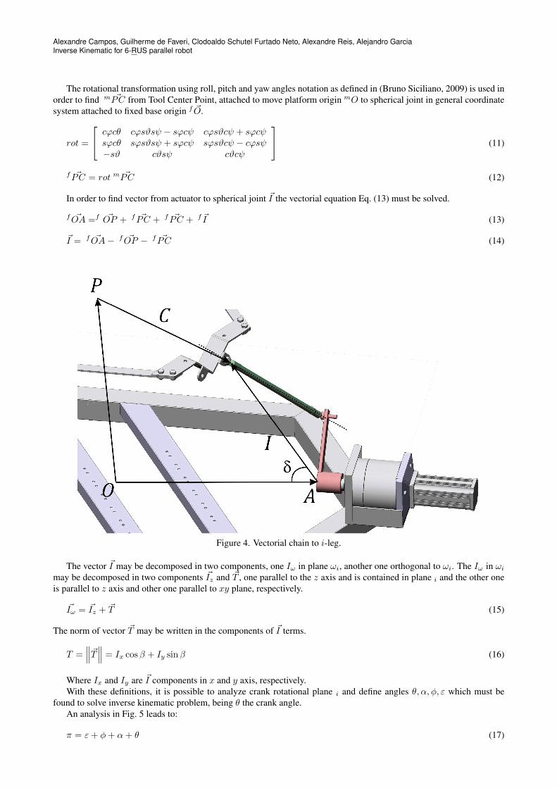
In order to find vector from actuator to spherical joint ~I the vectorial equation Eq. (13) must be solved.
f ~OA =f ~OP + f ~PC + f ~PC + f ~I (13)
~I = f ~OA− f ~OP − f ~PC (14)
Figure 4. Vectorial chain to i-leg.
The vector ~I may be decomposed in two components, one Iω in plane ωi, another one orthogonal to ωi. The Iω in ωi
may be decomposed in two components ~Iz and ~T , one parallel to the z axis and is contained in plane i and the other oneis parallel to z axis and other one parallel to xy plane, respectively.
~Iω = ~Iz + ~T (15)
The norm of vector ~T may be written in the components of ~I terms.
T =∥∥∥~T∥∥∥ = Ix cosβ + Iy sinβ (16)
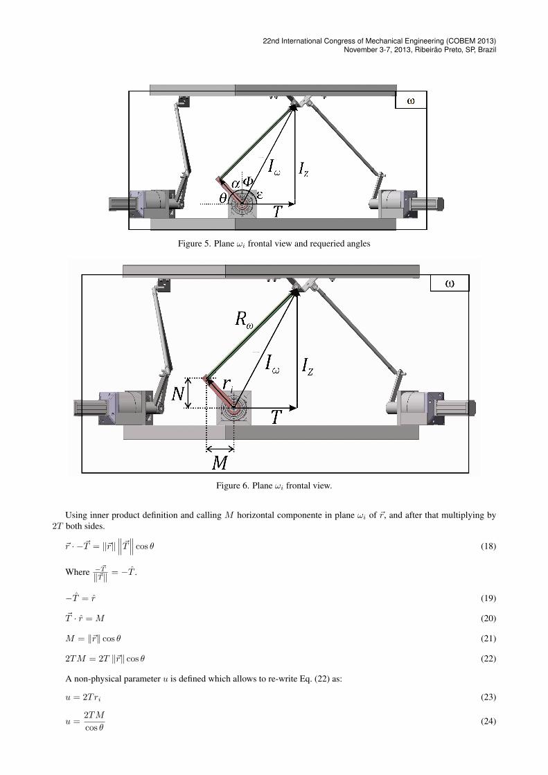
Where Ix and Iy are ~I components in x and y axis, respectively.With these definitions, it is possible to analyze crank rotational plane i and define angles θ, α, φ, ε which must be
found to solve inverse kinematic problem, being θ the crank angle.An analysis in Fig. 5 leads to:
π = ε+ φ+ α+ θ (17)
22nd International Congress of Mechanical Engineering (COBEM 2013)November 3-7, 2013, Ribeirão Preto, SP, Brazil
Figure 5. Plane ωi frontal view and requeried angles
Figure 6. Plane ωi frontal view.
Using inner product definition and calling M horizontal componente in plane ωi of ~r, and after that multiplying by2T both sides.
~r · −~T = ‖~r‖∥∥∥~T∥∥∥ cos θ (18)
Where −~T
‖~T‖ = −T .
−T = r (19)
~T · r =M (20)
M = ‖~r‖ cos θ (21)
2TM = 2T ‖~r‖ cos θ (22)
A non-physical parameter u is defined which allows to re-write Eq. (22) as:
u = 2Tri (23)
u =2TM
cos θ(24)
Alexandre Campos, Guilherme de Faveri, Clodoaldo Schutel Furtado Neto, Alexandre Reis, Alejandro GarciaInverse Kinematic for 6-RUS parallel robot
Using same method, other non-physical parameter v is defined, however the equation is multiplied by 2Iz .
v = −2Iz ‖~r‖ (25)
~r · Iz = ‖~r‖∥∥∥~Iz∥∥∥ cosα (26)
N = ‖~r‖ cosα (27)
Where N is vertical component of ~r and the formutaion is similarly to M .
2IzN = 2Iz ‖~r‖ cosα (28)
v =2IzN
cosα(29)
In these terms is it possible to define the relation between uv and determinate angle φ.
φ = arctanT
Iz(30)
u
v=
2TM cosα
2IzN cos θ(31)
M
N=
cos θ
cosα(32)
u
v= − T
Iz(33)
φ = − arctanu
v(34)
It is not necessary use this method to find φ once Iz and T are known, however since parameters u and v are usedafter, it is convenient to show the formulation.
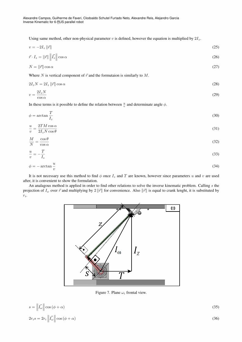
An analagous method is applied in order to find other relations to solve the inverse kinematic problem. Calling s theprojection of Iω over ~r and multiplying by 2 ‖~r‖ for convenience. Also ‖~r‖ is equal to crank lenght, it is substituted byri.
Figure 7. Plane ωi frontal view.
s =∥∥∥ ~Iω∥∥∥ cos (φ+ α) (35)
2ris = 2ri
∥∥∥ ~Iω∥∥∥ cos (φ+ α) (36)
22nd International Congress of Mechanical Engineering (COBEM 2013)November 3-7, 2013, Ribeirão Preto, SP, Brazil
Using the closed-loop equation it leads:∥∥∥~R∥∥∥2 =∥∥∥~I∥∥∥2 + ‖~r‖2 − ∥∥∥~I∥∥∥ ‖~r‖ cos δ (37)
Being δ the real angle crank and vector ~I . Analysing Eq. (37) in crank rotational plane, it is possible to affirm thatδ = α+ φ, and then is defined w, a non-physical parameter.
w = −2 ‖~r‖∥∥∥ ~Iω∥∥∥ cos δ (38)
w = R2i −
∥∥∥~I∥∥∥− r2i (39)
Also, it is possible to manipulate properly the geometrical equations of triangle rectangle showed in Fig. 7.
s2 =
(−w2ri
)2
(40)
u2 + v2 = (2Tri)2+ (−2Izri)2 (41)
u2 + v2 = (2ri)2(Iω)
2 (42)
From triangle rectangle showed in Fig. 7
z2 + s2 =∥∥∥ ~Iω∥∥∥2 (43)
(2ri)2z2 + (2ri)
2s2 = (2ri)
2∥∥∥ ~Iω∥∥∥2 (44)
Then is defined other non-physical parameter q and Eq. (44) re-written.
q = 2riz (45)
q2 + (2ri)2s2 = (2ri)
2∥∥∥ ~Iω∥∥∥2 (46)
Substituting Eq. (40) into Eq. (46):
q2 + w2 = (2ri)2∥∥∥ ~Iω∥∥∥2 (47)
q2 = (2ri)2
(∥∥∥ ~Iω∥∥∥2 − ∥∥∥ ~Iω∥∥∥2 cos (φ+ α)
)(48)
q2 = (2ri)2∥∥∥ ~Iω∥∥∥2 sin (φ+ α) (49)
q2
w2=
(2 ‖~r‖)2∥∥∥ ~Iω∥∥∥2 cos2 (φ+ α)
(2 ‖~r‖)2∥∥∥ ~Iω∥∥∥2 sin2 (φ+ α)
(50)
tan (φ+ α) =q
w(51)
φ+ α = arctanq
w(52)
Returning to Eq. (17).
π = ε+ φ+ α+ θ (53)
ε =π
2− φ (54)
π =(π2− φ
)+ (φ+ α) + θ (55)
θ =π
2+ φ− (φ+ α) (56)
θ =π
2− arctan
u
v− arctan
q
w(57)
In these terms, it is solved the inverse kinematic problem. Once function arctan has a dubious response, it is conve-nient to use atan2 function.
Alexandre Campos, Guilherme de Faveri, Clodoaldo Schutel Furtado Neto, Alexandre Reis, Alejandro GarciaInverse Kinematic for 6-RUS parallel robot
4. Results
This paper presented a method to solve the Inverse Kinematic Problem for a 6-RUS parallel robot using some non-physical parameters defined based on the vectorial equation to the chains. Tough the prove of the method is extensive, theapplication is simple. An algorithm that compute the joint and actuators position and compute the parameter u, v, w andq as presented solve the inverse kinematic problem using really low computational coast.
For convenience Eq. (23), Eq. (25), Eq. (39), Eq. (47) and Eq. (42) may be re-written to compute u, v, w and q basedin previously values and apply in Eq. (57).
u = 2ri (Ix cosβ + Iy sinβ) (58)
v = −2riIz (59)
w = R2i − r2i − I2x − I2y − I2z (60)
u2 + v2 = q2 + w2 (61)
q =√u2 + v2 − w2 (62)
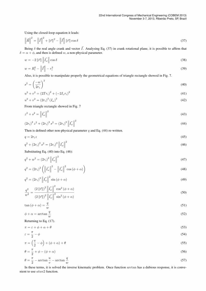
The same algorithm is useful to find the workspace to a given orientation using some increments to Px, Py and Pz
and solving the Inverse Kinematic Problem repeatedly it is possible to find the workspace of the parallel robot to a givenorientation. The CEART - Flight Simulator workspace is presented in Fig. 8 to a orientation ϕ, ϑ and ψ equal to zerodegrees.
Figure 8. Flight Simulator workspace to ϕ = 0, ϑ = 0, ψ = 0
5. REFERENCES
Advani, S.K., 1998. The Kinematic Design of Flight Simulatior Motion-Mases. Master’s thesis, University of Toronto.
22nd International Congress of Mechanical Engineering (COBEM 2013)November 3-7, 2013, Ribeirão Preto, SP, Brazil
Bonev, I.A., 2002. Geometric Analysis of Parallel Mechanisms. Ph.D. thesis, Facult’e des Sciences et de Gt’enie Univer-salt’e Laval.
Bruno Siciliano, Lorenzo Sciavicco, L.V.G.O., 2009. Robotics Modeling, Planning and Control. Springer.Carlos S.M. Coelho, Jorge A. Santos, C.F.d.S., 2007. “Enjoo de movimento: Etiologia, factores predisponentes e adap-
tação”. In Psicologia, Saúde & Doenças.Fichter, E., 1986. “A stewart based manipulator: General theory and pratical construction”. Internal Journal of Robotics
Research, Vol. 5, pp. 157–182.Haan, P., 1995. Design of the Motion System Gimbals of the SIMONA Research Simulator. Master’s thesis, Faculty of
Aerospace Engineering, Delft University of Technology.Merlet, J.P., 2010. Parallel Robots. Springer, Dordrecht, The Netherlands, 2nd edition.Page, R.L., 2010. “Brief history of flight simulation”. In SimTechT 2000 Proceedings.
6. RESPONSIBILITY NOTICE
The authors are the only responsible for the printed material included in this paper.