chapter 3: addressing modes · pdf file04.10.2012 · chapter objectives...
TRANSCRIPT

Addressing Modes

Introduction• Efficient software development for the
microprocessor requires a complete familiaritywith the addressing modes employed by eachinstruction.• This chapter explains the operation of the stack
memory so that the PUSH and POP instructionsand other stack operations willbe understood.
2

Chapter Objectives
• Explain the operation of each data-addressingmode.• Use the data-addressing modes to form assembly
language statements.• Explain the operation of each program memory-
addressing mode.• Use the program memory-addressing modes to
form assembly and machine language statements.
Upon completion of this chapter, you will be able to:
3

Chapter Objectives
• Select the appropriate addressing mode toaccomplish a given task.• Detail the difference between addressing memory
data using real mode and pro-tected modeoperation.• Describe sequence of events that place data onto
the stack or remove data from the stack.• Explain how a data structure is placed in memory
and used with software.
Upon completion of this chapter, you will be able to:
(cont.)
4

DATA ADDRESSING MODES• MOV instruction is a common and flexible instruction.– provides a basis for explanation of data-addressing modes
• Figure 3–1 illustrates the MOV instruction and definesthe direction of data flow.• Source is to the right and destination the left, next to
the opcode MOV.– an opcode, or operation code, tells the microprocessor
which operation to perform
5

Figure 3–1 The MOV instruction showing the source, destination, and direction of data flow.
6

• Figure 3–2 shows all possible variations of thedata-addressing modes using MOV.• These data-addressing modes are found with all
versions of the Intel microprocessor.– except for the scaled-index-addressing mode, found
only in 80386 through Core2
• RIP relative addressing mode is not illustrated.– only available on the Pentium 4 and Core2
in the 64-bit mode
7

Figure 3–2 8086–Core2 data-addressing modes.
8

Register Addressing• The most common form of data addressing.– once register names learned, easiest to apply.
• The microprocessor contains these 8-bit registernames used with register addressing: AH, AL, BH,BL, CH, CL, DH, and DL.• 16-bit register names: AX, BX, CX, DX, SP, BP, SI,
and DI.
9

• In 80386 & above, extended 32-bit register namesare: EAX, EBX, ECX, EDX, ESP, EBP, EDI, and ESI.• 64-bit mode register names are: RAX, RBX, RCX,
RDX, RSP, RBP, RDI, RSI, and R8 through R15.• Important for instructions to use registers that are
the same size.– never mix an 8-bit \with a 16-bit register, an 8- or a 16-
bit register with a 32-bit register– this is not allowed by the microprocessor and results
in an error when assembled
10

Figure 3–3 The effect of executing the MOV BX, CX instruction at the point just before the BXregister changes. Note that only the rightmost 16 bits of register EBX change.
11

• Figure 3–3 shows the operation of the MOV BX,CX instruction.• The source register’s contents do not change.– the destination register’s contents do change
• The contents of the destination register ordestination memory location change for allinstructions except the CMP and TESTinstructions.• The MOV BX, CX instruction does not affect the
leftmost 16 bits of register EBX.
12

Immediate Addressing• Term immediate implies that data immediately
follow the hexadecimal opcode in the memory.– immediate data are constant data– data transferred from a register or memory location
are variable data
• Immediate addressing operates upon a byte orword of data.• Figure 3–4 shows the operation of a MOV
EAX,13456H instruction.
13

Figure 3–4 The operation of the MOV EAX,3456H instruction. This instruction copies theimmediate data (13456H) into EAX.
• As with the MOV instruction illustrated in Figure3–3, the source data overwrites the destinationdata.
14
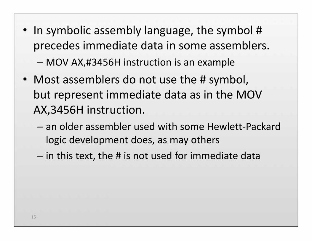
• In symbolic assembly language, the symbol #precedes immediate data in some assemblers.–MOV AX,#3456H instruction is an example
• Most assemblers do not use the # symbol,but represent immediate data as in the MOVAX,3456H instruction.– an older assembler used with some Hewlett-Packard
logic development does, as may others– in this text, the # is not used for immediate data
15

• The symbolic assembler portrays immediate datain many ways.• The letter H appends hexadecimal data.• If hexadecimal data begin with a letter, the
assembler requires the data start with a 0.– to represent a hexadecimal F2, 0F2H is used
in assembly language
• Decimal data are represented as is and require nospecial codes or adjustments.– an example is the 100 decimal in the
MOV AL,100 instruction
16

• An ASCII-coded character or characters may bedepicted in the immediate form if the ASCII dataare enclosed in apostrophes.– be careful to use the apostrophe (‘) for ASCII
data and not the single quotation mark (‘)
• Binary data are represented if the binary numberis followed by the letter B.– in some assemblers, the letter Y
17

• Each statement in an assembly language programconsists of four parts or fields.• The leftmost field is called the label.– used to store a symbolic name for the memory
location it represents
• All labels must begin with a letter or one of thefollowing special characters: @, $, -, or ?.– a label may any length from 1 to 35 characters
• The label appears in a program to identify thename of a memory location for storing data andfor other purposes.
18

• The next field to the right is the opcode field.– designed to hold the instruction, or opcode– the MOV part of the move data instruction is an
example of an opcode
• Right of the opcode field is the operand field.– contains information used by the opcode– the MOV AL,BL instruction has the opcode MOV and
operands AL and BL
• The comment field, the final field, contains acomment about the instruction(s).– comments always begin with a semicolon (;)
19

Direct Data Addressing• Applied to many instructions in a typical program.• Two basic forms of direct data addressing:– direct addressing, which applies to a MOV between a
memory location and AL, AX, or EAX– displacement addressing, which applies to almost any
instruction in the instruction set
• Address is formed by adding the displacement tothe default data segment address or an alternatesegment address.
20

Direct Addressing• Direct addressing with a MOV instruction transfers
data between a memory location, located withinthe data segment, and the AL (8-bit), AX (16-bit),or EAX (32-bit) register.– usually a 3-byte long instruction
• MOV AL,DATA loads AL from the data segmentmemory location DATA (1234H).– DATA is a symbolic memory location, while
1234H is the actual hexadecimal location
21

Figure 3–5 The operation of the MOV AL,[1234H] instruction when DS=1000H .
• This instruction transfers a copy contents ofmemory location 11234H into AL.– the effective address is formed by adding
1234H (the offset address) and 10000H(the data segment address of 1000H times10H) in a system operating in the real mode
22

Displacement Addressing• Almost identical to direct addressing, except the
instruction is 4 bytes wide instead of 3.• In 80386 through Pentium 4, this instruction can
be up to 7 bytes wide if a 32-bit register and a 32-bit displacement are specified.• This type of direct data addressing is much more
flexible because most instructions use it.
23

Register Indirect Addressing• Allows data to be addressed at any memory
location through an offset address held in any ofthe following registers: BP, BX, DI, and SI.• In addition, 80386 and above allow register
indirect addressing with any extended registerexcept ESP.• In the 64-bit mode, the segment registers serve no
purpose in addressing a locationin the flat model.
24

Figure 3–6 The operation of the MOV AX,[BX] instruction when BX = 1000H and DS = 0100H.Note that this instruction is shown after the contents of memory are transferred to AX.
25

• The data segment is used by default with registerindirect addressing or any other mode that usesBX, DI, or SI to address memory.• If the BP register addresses memory, the stack
segment is used by default.– these settings are considered the default for
these four index and base registers
• For the 80386 and above, EBP addresses memoryin the stack segment by default.• EAX, EBX, ECX, EDX, EDI, and ESI address memory
in the data segment by fault.
26

• When using a 32-bit register to address memoryin the real mode, contents of the register mustnever exceed 0000FFFFH.• In the protected mode, any value can be used in a
32-bit register that is used to indirectly addressmemory.– as long as it does not access a location outside
the segment, dictated by the access rights byte
• In the 64-bit mode, segment registers arenot used in address calculation; the registercontains the actual linear memory address.
27

• In some cases, indirect addressing requiresspecifying the size of the data by the specialassembler directive BYTE PTR, WORD PTR,DWORD PTR, or QWORD PTR.– these directives indicate the size of the memory data
addressed by the memory pointer (PTR)
• The directives are with instructions that address amemory location through apointer or index register with immediate data.• With SIMD instructions, the octal OWORD PTR,
represents a 128-bit-wide number.
28

• Indirect addressing often allows a program torefer to tabular data located in memory.• Figure 3–7 shows the table and the BX register
used to sequentially address each location in thetable.• To accomplish this task, load the starting location
of the table into the BX registerwith a MOV immediate instruction.• After initializing the starting address of the table,
use register indirect addressing tostore the 50 samples sequentially.
29

Figure 3–7 An array (TABLE) containing 50 bytes that are indirectly addressed throughregister BX.
30

Base-Plus-Index Addressing• Similar to indirect addressing because it indirectly
addresses memory data.• The base register often holds the beginning
location of a memory array.– the index register holds the relative position
of an element in the array– whenever BP addresses memory data, both the stack
segment register and BP generate the effective address
31

Locating Data with Base-Plus-IndexAddressing
• Figure 3–8 shows how data are addressed by theMOV DX,[BX + DI] instruction when themicroprocessor operates in the real mode.• The Intel assembler requires this addressing mode
appear as [BX][DI] instead of [BX + DI].• The MOV DX,[BX + DI] instruction is MOV
DX,[BX][DI] for a program written for the Intel ASMassembler.
32

Figure 3–8 An example showing how the base-plus-index addressing mode functions for the MOV DX,[BX+ DI] instruction. Notice that memory address 02010H is accessed because DS=0100H, BX=100H and
DI=0010H.
33

Locating Array Data Using Base-Plus-IndexAddressing
• A major use is to address elements in a memoryarray.• To accomplish this, load the BX register (base) with
the beginning address of the array and the DIregister (index) with the element number to beaccessed.• Figure 3–9 shows the use of BX and DI to access an
element in an array of data.
34

Figure 3–9 An example of the base-plus-index addressing mode. Here an element (DI) of anARRAY (BX) is addressed.
35

Register Relative Addressing• Similar to base-plus-index addressing and
displacement addressing.– data in a segment of memory are addressed by adding
the displacement to the contents of a base or an indexregister (BP, BX, DI, or SI)
• Figure 3–10 shows the operation of the MOVAX,[BX+1000H] instruction.• A real mode segment is 64K bytes long.
36

Figure 3–10 The operation of the MOV AX, [BX+1000H] instruction, when BX=1000H andDS=0200H .
37

Addressing Array Data with Register Relative
• It is possible to address array data with registerrelative addressing.– such as with base-plus-index addressing
• In Figure 3–11, register relative addressing isillustrated with the same example as for base-plus-index addressing.– this shows how the displacement ARRAY adds
to index register DI to generate a reference toan array element
38

Figure 3–11 Register relative addressing used to address an element of ARRAY. Thedisplacement addresses the start of ARRAY, and DI accesses an element.
39

Base Relative-Plus-Index Addressing
• Similar to base-plus-index addressing.– adds a displacement– uses a base register and an index register to
form the memory address
• This type of addressing mode often addresses atwo-dimensional array of memory data.
40

Addressing Data with Base Relative-Plus-Index
• Least-used addressing mode.• Figure 3–12 shows how data are referenced if the
instruction executed by the microprocessor isMOV AX,[BX + SI + 100H].– displacement of 100H adds to BX and SI to form the
offset address within the data segment
• This addressing mode is too complex for frequentuse in programming.
41

Figure 3–12 An example of base relative-plus-index addressing using a MOVAX,[BX+SI=1000H] instruction. Note: DS=1000H
42

Addressing Arrays with Base Relative-Plus-Index
• Suppose a file of many records exists in memory,each record with many elements.– displacement addresses the file, base register
addresses a record, the index register addresses anelement of a record
• Figure 3–13 illustrates this very complex form ofaddressing.
43

Figure 3–13 Base relative-plus-index addressing used to access a FILE that contains multiplerecords (REC).
44

Scaled-Index Addressing• Unique to 80386 - Core2 microprocessors.– uses two 32-bit registers (a base register and
an index register) to access the memory
• The second register (index) is multiplied by ascaling factor.– the scaling factor can be 1x, 2x, 4x, 8x
• A scaling factor of is implied and need not beincluded in the assembly language instruction(MOV AL,[EBX + ECX]).
45

RIP Relative Addressing• Uses the 64-bit instruction pointer register in the
64-bit mode to address a linear locationin the flat memory model.• Inline assembler program available to Visual does
not contain any way of using this mode or anyother 64-bit addressing mode.• The Microsoft Visual does not at present support
developing 64-bit assembly code.
46

Data Structures• Used to specify how information is stored in a
memory array.– a template for data
• The start of a structure is identified with theSTRUC assembly language directive and the endwith the ENDS statement.
47

PROGRAM MEMORY-ADDRESSING MODES
• Used with the JMP (jump) and CALL instructions.• Consist of three distinct forms:– direct, relative, and indirect
48

Direct Program Memory Addressing• Used for all jumps and calls by early
microprocessor; also used in high-level languages,such as BASIC.– GOTO and GOSUB instructions
• The microprocessor uses this form, but not asoften as relative and indirect program memoryaddressing.• The instructions for direct program memory
addressing store the address with the opcode.
49

Figure 3–14 The 5-byte machine language version of a JMP [10000H] instruction.
50

• This JMP instruction loads CS with 1000H and IPwith 0000H to jump to memory location 10000Hfor the next instruction.– an intersegment jump is a jump to any memory
location within the entire memory system
• Often called a far jump because it can jump to anymemory location for the next instruction.– in real mode, any location within the first 1M byte– In protected mode operation, the far jump can jump
to any location in the 4G-byte addressrange in the 80386 - Core2 microprocessors
51

• The only other instruction using direct programaddressing is the intersegment or far CALLinstruction.• Usually, the name of a memory address, called a
label, refers to the location that is called orjumped to instead of the actual numeric address.• When using a label with the CALL or JMP
instruction, most assemblers select the best formof program addressing.
52

Relative Program Memory Addressing
• Not available in all early microprocessors, but it isavailable to this family of microprocessors.• The term relative means “relative to the
instruction pointer (IP)”.• The JMP instruction is a 1-byte instruction, with a
1-byte or a 2-byte displacement that adds to theinstruction pointer.• An example is shown in Figure 3–15.
53

Figure 3–15 A JMP [2] instruction. This instruction skips over the 2 bytes of memory thatfollow the JMP instruction.
54

Indirect Program Memory Addressing
• The microprocessor allows several forms ofprogram indirect memory addressing for the JMPand CALL instructions.• In 80386 and above, an extended register can be
used to hold the address or indirect address of arelative JMP or CALL.– for example, the JMP EAX jumps to the
location address by register EAX
55

• If a relative register holds the address, the jump isconsidered to be an indirect jump.• For example, JMP [BX] refers to the memory
location within the data segment at the offsetaddress contained in BX.– at this offset address is a 16-bit number used as the
offset address in the intrasegment jump– this type of jump is sometimes called an indirect-
indirect or double-indirect jump• Figure 3–16 shows a jump table that is stored,
beginning at memory location TABLE.
56

Figure 3–16 A jump table that stores addresses of various programs. The exact addresschosen from the TABLE is determined by an index stored with the jump instruction.
57

STACK MEMORY-ADDRESSING MODES
• The stack plays an important role in allmicroprocessors.– holds data temporarily and stores return addresses
used by procedures
• Stack memory is LIFO (last-in, first-out) memory– describes the way data are stored and removed from
the stack
58

• Data are placed on the stack with a PUSHinstruction; removed with a POP instruction.• Stack memory is maintained by two registers:– the stack pointer (SP or ESP)– the stack segment register (SS)
• Whenever a word of data is pushed onto the stack,the high-order 8 bits are placed in the locationaddressed by SP – 1.– low-order 8 bits are placed in the location addressed by
SP – 2
59

• The SP is decremented by 2 so the next word isstored in the next available stack location.– the SP/ESP register always points to an area of memory
located within the stack segment.• In protected mode operation, the SS register holds
a selector that accesses a descriptor for the baseaddress of the stack segment.• When data are popped from the stack, the low-
order 8 bits are removed from the locationaddressed by SP.– high-order 8 bits are removed; the SP register is
incremented by 2
60

Figure 3–17 The PUSH and POP instructions: (a) PUSH BX places the contents of BX onto the stack; (b)POP CX removes data from the stack and places them into CX. Both instructions are shown after
execution.
61

• Note that PUSH and POP store or retrieve wordsof data—never bytes—in 8086 - 80286.• 80386 and above allow words or doublewords to
be transferred to and from the stack.• Data may be pushed onto the stack from any 16-
bit register or segment register.– in 80386 and above, from any 32-bit extended register
• Data may be popped off the stack into anyregister or any segment register except CS.
62

• PUSHA and POPA instructions push or pop allexcept segment registers, on the stack.• Not available on early 8086/8088 processors.• 80386 and above allow extended registers to be
pushed or popped.– 64-bit mode for Pentium and Core2 does not contain a
PUSHA or POPA instruction
63