chapter 1 the princple for efi and actuator - tu sitio de...
TRANSCRIPT
Chery QQ Maintenance Manual 372 EFI System
Chery Automobile Co., Ltd
1
Chapter 1 The princple for EFI and actuator
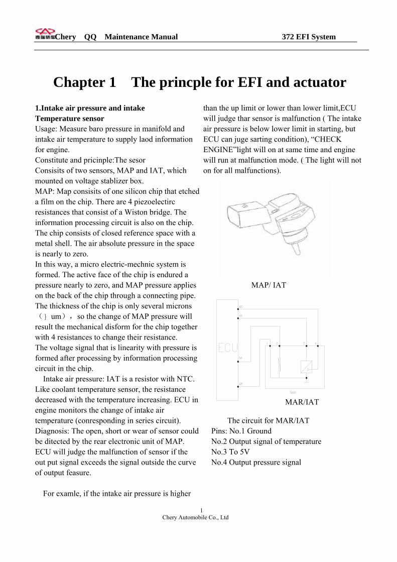
1.Intake air pressure and intake Temperature sensor Usage: Measure baro pressure in manifold and intake air temperature to supply laod information for engine. Constitute and pricinple:The sesor Consisits of two sensors, MAP and IAT, which mounted on voltage stablizer box. MAP: Map consisits of one silicon chip that etched a film on the chip. There are 4 piezoelectirc resistances that consist of a Wiston bridge. The information processing circuit is also on the chip. The chip consists of closed reference space with a metal shell. The air absolute pressure in the space is nearly to zero. In this way, a micro electric-mechnic system is formed. The active face of the chip is endured a pressure nearly to zero, and MAP pressure applies on the back of the chip through a connecting pipe. The thickness of the chip is only several microns( um),so the change of MAP pressure will result the mechanical disform for the chip together with 4 resistances to change their resistance. The voltage signal that is linearity with pressure is formed after processing by information processing circuit in the chip.
Intake air pressure: IAT is a resistor with NTC. Like coolant temperature sensor, the resistance decreased with the temperature increasing. ECU in engine monitors the change of intake air temperature (conresponding in series circuit). Diagnosis: The open, short or wear of sensor could be ditected by the rear electronic unit of MAP. ECU will judge the malfunction of sensor if the out put signal exceeds the signal outside the curve of output feasure.
For examle, if the intake air pressure is higher
than the up limit or lower than lower limit,ECU will judge thar sensor is malfunction ( The intake air pressure is below lower limit in starting, but ECU can juge sarting condition), “CHECK ENGINE”light will on at same time and engine will run at malfunction mode. ( The light will not on for all malfunctions).
MAP/ IAT
进气压力温度传感器
The circuit for MAR/IAT
MAR/IAT
Pins: No.1 Ground No.2 Output signal of temperature No.3 To 5V No.4 Output pressure signal
Chery QQ Maintenance Manual 372 EFI System
Chery Automobile Co., Ltd
2
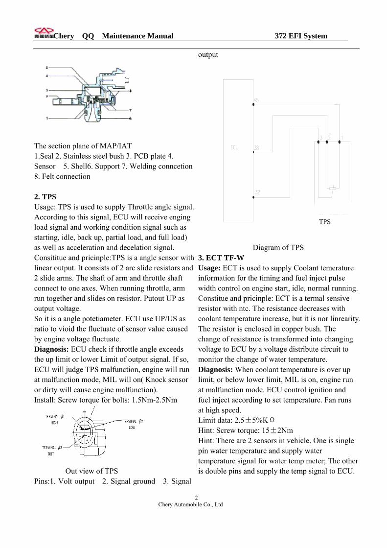
The section plane of MAP/IAT 1.Seal 2. Stainless steel bush 3. PCB plate 4. Sensor 5. Shell6. Support 7. Welding conncetion 8. Felt connection 2. TPS Usage: TPS is used to supply Throttle angle signal. According to this signal, ECU will receive enging load signal and working condition signal such as starting, idle, back up, partial load, and full load) as well as acceleration and decelation signal. Consititue and pricinple:TPS is a angle sensor with linear output. It consists of 2 arc slide resistors and 2 slide arms. The shaft of arm and throttle shaft connect to one axes. When running throttle, arm run together and slides on resistor. Putout UP as output voltage. So it is a angle potetiameter. ECU use UP/US as ratio to vioid the fluctuate of sensor value caused by engine voltage fluctuate. Diagnosis: ECU check if throttle angle exceeds the up limit or lower Limit of output signal. If so, ECU will judge TPS malfunction, engine will run at malfunction mode, MIL will on( Knock sensor or dirty will cause engine malfunction). Install: Screw torque for bolts: 1.5Nm-2.5Nm
Out view of TPS
Pins:1. Volt output 2. Signal ground 3. Signal
output
节气门位置传感器
PS
Diagram of TPS 3. ECT TF-W Usage: ECT is used to supply Coolaninformation for the timing and fuel inwidth control on engine start, idle, noConstitue and pricinple: ECT is a termresistor with ntc. The resistance decrecoolant temperature increase, but it isThe resistor is enclosed in copper buschange of resistance is transformed involtage to ECU by a voltage distributmonitor the change of water temperatDiagnosis: When coolant temperaturelimit, or below lower limit, MIL is onat malfunction mode. ECU control ignfuel inject according to set temperaturat high speed. Limit data: 2.5±5%KΩ Hint: Screw torque: 15±2Nm Hint: There are 2 sensors in vehicle. Opin water temperature and supply wattemperature signal for water temp meis double pins and supply the temp sig
T
t temerature ject pulse rmal running. al sensive
ases with nor linrearity. h. The to changing e circuit to ure. is over up , engine run ition and e. Fan runs
ne is single er ter; The other nal to ECU.

Chery QQ Maintenance Manual 372 EFI System
Chery Automobile Co., Ltd
3
Diagram of ECT
Pins: There are 3 pins which could be interexchangable. a. EFI water temperature signal pin, resistance
is 2.45KΩ at 200C. b. Instrument water temperature signal pin,
resistance is 0.05KΩ at 800C. c. Signal ground
接仪表
b
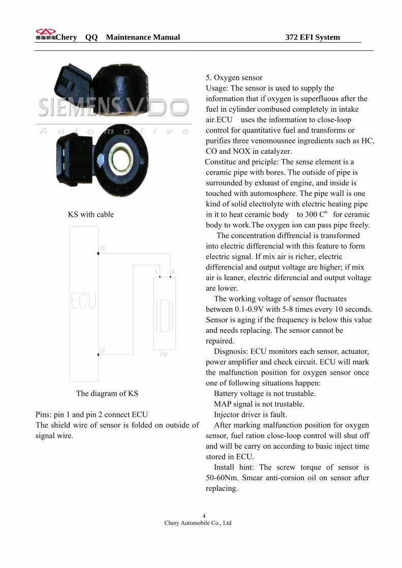
Circuit diagram of ECT Hint: There are 1 water temperature sensor with 3 lines on it. One is ower line, two are signal lines which one to ECU and the other to instrument. 4. KS Usage: Supply knock signal to ECU for knock control. Consititution and principle: KS is vibration accelaration sensor mounted
onengine. The sense element is a piezoelectricity element. The vibration of cylinder is transformed to piezoelectrical crystal through mass block in sensor. The pressure of crystal produce voltage on two polar faces and change vibration signal into output AC voltage signal. Because the frequency of vibration caused by engine knock is much higher than normal frequency of engine vibration signal, so ECU can distingquish knock and unknock signals after filtering the signal of KS. When engine load, speed and coolant temperature exceed gate value, and not set KS malfunction information record, the signal of KS will be used to close loop control for knocking. When the control is actuated, the signal of KS will input to ECU for integral after amplify and filter. When certain integral value in crank angle exceeds gate value, ECU will consider the knock happens, and reduce 1 degree of ignitionadvanced-angle. If knock happens on next cycle, ECU will reduce 1 degree of ignitionadvanced-angle again; If no knocks happen in next cycles, ECU will resume the angle to normal value. Diagnosis: ECU monitors each sensor, actuator, power amplifier and check circuit. KS will mark malfunction position once following situations happen:
KS malfunction KS control data process circuit malfunction Cyinder identification signal is untrustable
After KS marks the malfunction position, knock close loop control will shut off and reduce 1 safty degree for ignition advanced-angle stored in ECU. When wrong frenquency is below set value, malfunction position will resume. Hint: Screw torque 20± 5Nm .
Chery QQ Maintenance Manual 372 EFI System
KS with cable
震传感器
The diagram of KS Pins: pin 1 and pin 2 connect ECU The shield wire of sensor is folded signal wire.
5. Oxygen sensor Usage: The sensor is used to supply the information that if oxygen is superfluous after the fuel in cylinder combused completely in intake air.ECU uses the information to close-loop control for quantitative fuel and transforms or purifies three venomousnee ingredients such as HC, CO and NOX in catalyzer. Constitue and priciple: The sense element is a ceramic pipe with bores. The outside of pipe is surrounded by exhaust of engine, and inside is touched with automosphere. The pipe wall is one kind of solid electrolyte with electric heating pipe in it to heat ceramic body to 300 Cº for ceramic body to work.The oxygen ion can pass pipe freely.
The concentration diffrencial is transformed into electric differencial with this feature to form electric signal. If mix air is richer, electric differencial and output voltage are higher; if mix air is leaner, electric diferencial and output voltage are lower.
The working voltage of sensor fluctuates between 0.1-0.9V with 5-8 times every 10 seconds. Sensor is aging if the frequency is below this value and needs replacing. The sensor cannot be repaired. Disgnosis: ECU monitors each sensor, actuator, power amplifier and check circuit. ECU will mark
爆Chery Automobile Co., Ltd
4
on outside of
the malfunction position for oxygen sensor once one of following situations happen: Battery voltage is not trustable. MAP signal is not trustable. Injector driver is fault. After marking malfunction position for oxygen sensor, fuel ration close-loop control will shut off and will be carry on according to basic inject time stored in ECU. Install hint: The screw torque of sensor is 50-60Nm. Smear anti-corsion oil on sensor after replacing.
Chery QQ Maintenance Manual 372 EFI System
Chery Automobile Co., Ltd
5
Oxygen sensor
主继电器
氧传感器
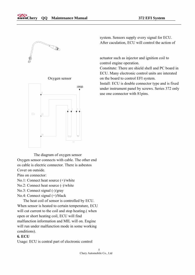
The diagram of oxygen sensor
Oxygen sensor connects with cable. The other end os cable is electric connector. There is asbestos Cover on outside. Pins on connector: No.1: Connect heat source (+)/white No.2: Connect heat source (-)/white No.3: Connect signal (-)/gray No.4: Connect signal (+)/black The heat coil of sensor is controlled by ECU. When sensor is heated to certain temperature, ECU will cut current to the coil and stop heating.( when open or short heating coil, ECU will find malfunction information and MIL will on. Engine will run under malfunction mode in some working conditions). 6. ECU Usage: ECU is central part of electronic control
system. Sensors supply every signal for ECU. After caculation, ECU will control the action of actuator such as injector and ignition coil to control engine operation. Constitute: There are shield shell and PC board in ECU. Many electronic control units are interated on the board to control EFI system. Install: ECU is double connector type and is fixed under instrument panel by screws. Series 372 only use one connector with 81pins.

Chery QQ Maintenance Manual 372 EFI System
Chery Automobile Co., Ltd
6
ECU pins: 1. Battery ground 29. CKP input 57. Not used 2. Battery ground 30. CMP ground 58. A/C apply 3. 3 Ignition coil 3 31.Water temperaturesignal 59.O2 ground 4. Ignition coil 1 32.TPS input 60. IAT ground 5. Ignition coil2 33. Not used 61. Injector of No.2 cylinder2 6. Can Bus lowCAN 34. Not used 62. Not used 7. Canbus highCAN 35. Step motor B+ 63. ECU powerECU) 8. O2 sensor 36. Step motor B - 64.High speed fan relay control output 9. Not used 37. Not used 10. KS signal 38. TPS ground 65. High Speed fan relay control output 11. Not used 39 Speed signal 66. Engine speed input signal 12. Evaporator temperature sensor input 40. Not used 67. Main relay control output 13. Evaporator temperature sensor ground 41. Not used 68. A/Crelay control output 14. Not used 42. Not used 69. Fuel pump relay output 15. Not used 43.O2 sensor 70. Trouble lamp 16. Not used 44. ECU power(+12V BAT) 71. Not used 17. Not used 45.TPS power supply(+5V) 18. Not used 46. IAT power supply(+5V) 19. Step motor A + 47. Not used 72. CKP input 20. Step motor A - 48 IAT ground 73. Water teperature sensor ground 21. Main relay power supply 49. Not used 74. Power steering pressure switch signal 22. Ignition switch power supply 50. 75. Not used 23. No.3 injection nozzle 51. Not used 76. Not used 24. No.1 injection nozzle 52 Not used 77. Diagnostic(K wire) 25. Not used 53. Not used 78. Not used 26. Canistor relay 54. KS ground 79. Not used 27. CKP ground 55. Ignition coil ground 80. Not used 28. Not used 56. IAT signal 81. Not used
Pins and out view of connector
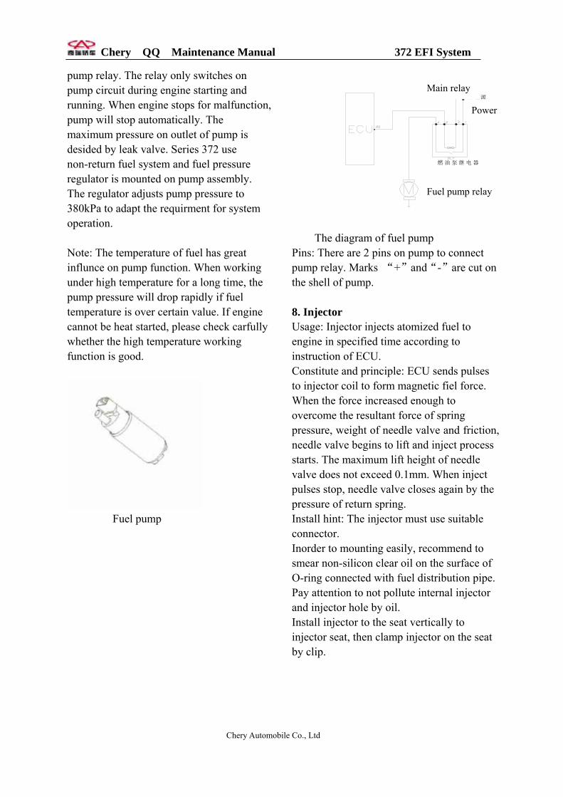
7. Fuel pump Usage: Fuel pump feeds fuel with certain pressure and quantity to engine. The temperature and voltage have great influnce on pump. Constitute and principle: The pump
consistsof DC motro, vane motor and cover( together with stop return valve, leak valve and anti-electromaganatic
interference elements). The pump and motor are mounted on same shaft and sealed in same shell. Pump and motor in
shell are surouned by fuel for radiation and lubrication. Battery supplies voltage to pump through
Chery QQ Maintenance Manual 372 EFI System
pump relay. The relay only switches on pump circuit during engine starting and running. When engine stops for malfunction, pump will stop automatically. The maximum pressure on outlet of pump is desided by leak valve. Series 372 use non-return fuel system and fuel pressure regulator is mounted on pump assembly. The regulator adjusts pump pressure to 380kPa to adapt the requirment for system operation.
Note: The temperature of fuel has great influnce on pump function. When working under high temperature for a long time, the pump pressure will drop rapidly if fuel temperature is over certain value. If engine cannot be heat started, please check carfully whether the high temperature working function is good.
Fuel pump
燃油泵继电器
主继电器
主电源
Main relay
Power
Fuel pump relay
The diagram of fuel pump Pins: There are 2 pins on pump to connect pump relay. Marks “+”and“-”are cut on the shell of pump. 8. Injector Usage: Injector injects atomized fuel to engine in specified time according to instruction of ECU. Constitute and principle: ECU sends pulses to injector coil to form magnetic fiel force. When the force increased enough to overcome the resultant force of spring pressure, weight of needle valve and friction, needle valve begins to lift and inject process starts. The maximum lift height of needle valve does not exceed 0.1mm. When inject pulses stop, needle valve closes again by the pressure of return spring. Install hint: The injector must use suitable connector. Inorder to mounting easily, recommend to smear non-silicon clear oil on the surface of O-ring connected with fuel distribution pipe. Pay attention to not pollute internal injector and injector hole by oil. Install injector to the seat vertically to injector seat, then clamp injector on the seat by clip.
Chery Automobile Co., Ltd

Chery QQ Maintenance Manual 372 EFI System
Note: For long stopped vehicle, please check carefully if the fuel cohered blocks injector. Diagnosis: S11 EFI system does not diagnose the injector itself, but diagnoses for injector driver. When injector driver is short to battery voltage or overload, short to ground or open, ECU will mark malfunction position. Oxygen sensor close-loop control and self-study pre-control will shut off. The last self-study data is effective. After troubleshooting, malfunction position resumes.
Injector
主继电器
缸 缸 缸
喷油器组
The diagram of injector
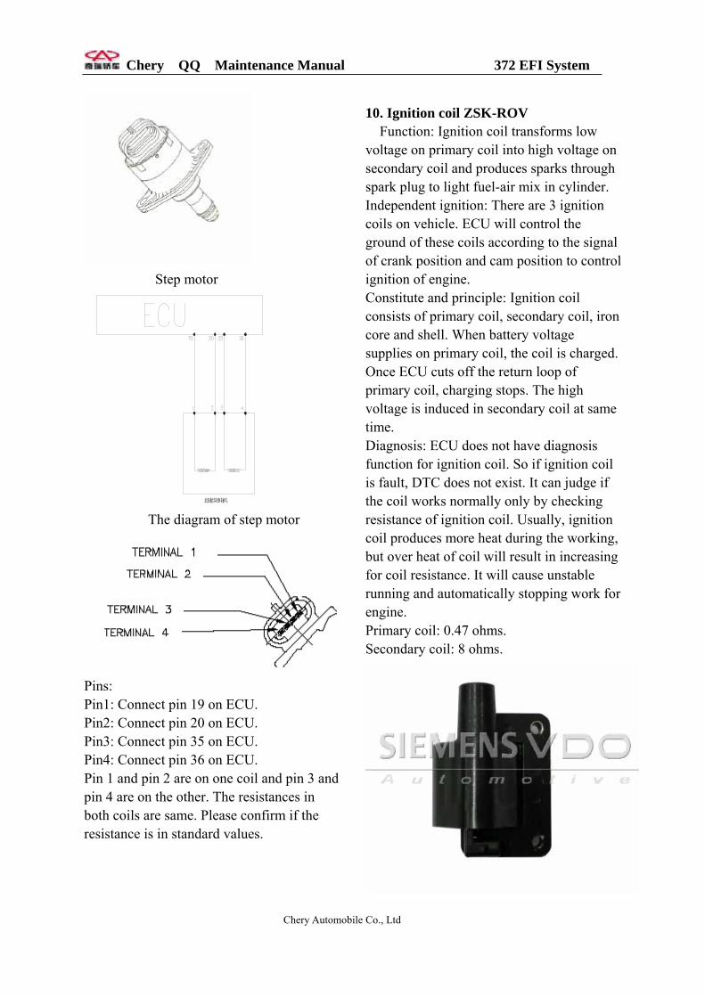
Pins: There are 2 pins on each injector. One of pins marked (+) on side of shell connects pin 87 on pump relay, and another connects pin 23,24 or 61 on ECU. 9. Step motor DLA Function: Step motor with idle actuator offers by-pass intake air channel. When throttle closes, air will enter engine through the channel. ECU can regulate the section of chennel to adjust mass airflow and adjust inject fuel amount. When engine works, ECU will control step motor according to different working conditions to change the operation of engine. Constitute and principle: Step motor is a micro motor that consists of several steel stators and one rotor. A coil is reeled on each stator. Rotor is a perminent maganet with a nut on the center. All stator coils is always connected with electricity. If changing current direction in one coil, rotor will turn a degree. When current direction in each stator coil is changed in suitable order, revolutionary field is formed to run rotor in certain direction. Disgnosis: ECU can monitor the short or open of two coils for step motor and lights MIL. Engine runs at malfunction mode. Some time use test can find the steps changing, but engine still does not work normally. Please check if intake air pressure changes to confirm is the piston of step motor works.
Chery Automobile Co., Ltd
Chery QQ Maintenance Manual 372 EFI System
Step motor
怠速步进电机 The diagram of step motor
Pins: Pin1: Connect pin 19 on ECU. Pin2: Connect pin 20 on ECU. Pin3: Connect pin 35 on ECU. Pin4: Connect pin 36 on ECU. Pin 1 and pin 2 are on one coil and pin 3 and pin 4 are on the other. The resistances in both coils are same. Please confirm if the resistance is in standard values.
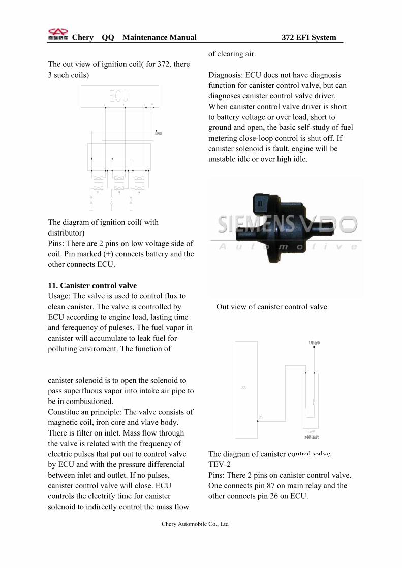
10. Ignition coil ZSK-ROV Function: Ignition coil transforms low voltage on primary coil into high voltage on secondary coil and produces sparks through spark plug to light fuel-air mix in cylinder. Independent ignition: There are 3 ignition coils on vehicle. ECU will control the ground of these coils according to the signal of crank position and cam position to control ignition of engine. Constitute and principle: Ignition coil consists of primary coil, secondary coil, iron core and shell. When battery voltage supplies on primary coil, the coil is charged. Once ECU cuts off the return loop of primary coil, charging stops. The high voltage is induced in secondary coil at same time. Diagnosis: ECU does not have diagnosis function for ignition coil. So if ignition coil is fault, DTC does not exist. It can judge if the coil works normally only by checking resistance of ignition coil. Usually, ignition coil produces more heat during the working, but over heat of coil will result in increasing for coil resistance. It will cause unstable running and automatically stopping work for engine. Primary coil: 0.47 ohms. Secondary coil: 8 ohms.
Chery Automobile Co., Ltd
Chery QQ Maintenance Manual 372 EFI System
The out view of ignition coil( for 372, there 3 such coils)
主继电器
The diagram of ignition coil( with distributor) Pins: There are 2 pins on low voltage side of coil. Pin marked (+) connects battery and the other connects ECU. 11. Canister control valve Usage: The valve is used to control flux to clean canister. The valve is controlled by ECU according to engine load, lasting time and ferequency of puleses. The fuel vapor in canister will accumulate to leak fuel for polluting enviroment. The function of canister solenoid is to open the solenoid to pass superfluous vapor into intake air pipe to be in combustioned. Constitue an principle: The valve consists of magnetic coil, iron core and vlave body. There is filter on inlet. Mass flow through the valve is related with the frequency of electric pulses that put out to control valve by ECU and with the pressure differencial between inlet and outlet. If no pulses, canister control valve will close. ECU controls the electrify time for canister solenoid to indirectly control the mass flow
of clearing air. Diagnosis: ECU does not have diagnosis function for canister control valve, but can diagnoses canister control valve driver. When canister control valve driver is short to battery voltage or over load, short to ground and open, the basic self-study of fuel metering close-loop control is shut off. If canister solenoid is fault, engine will be unstable idle or over high idle.
Out view of canister control valve
炭罐电磁阀
主继电器
The diagram of canister con rol valve TEV-2 Pins: There 2 pins on canistOne connects pin 87 on maother connects pin 26 on EC
Chery Automobile Co., Ltd
t
er control valve. in relay and the U.
Chery QQ Maintenance Manual 372 EFI System
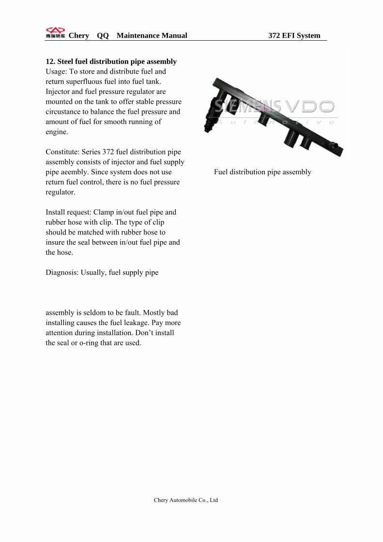
12. Steel fuel distribution pipe assembly Usage: To store and distribute fuel and return superfluous fuel into fuel tank. Injector and fuel pressure regulator are mounted on the tank to offer stable pressure circustance to balance the fuel pressure and amount of fuel for smooth running of engine. Constitute: Series 372 fuel distribution pipe assembly consists of injector and fuel supply pipe aeembly. Since system does not use return fuel control, there is no fuel pressure regulator. Install request: Clamp in/out fuel pipe and rubber hose with clip. The type of clip should be matched with rubber hose to insure the seal between in/out fuel pipe and the hose. Diagnosis: Usually, fuel supply pipe assembly is seldom to be fault. Mostly bad installing causes the fuel leakage. Pay more attention during installation. Don’t install the seal or o-ring that are used.
Fuel distribution pipe assembly
Chery Automobile Co., Ltd
Chery QQ Maintenance Manual 372 EFI System
Chapter 2 Basic principle for diagnosis of EFI (1) Fault information record ECU continually detect the sensors, actuator, related circuit, MIL and battery voltage as well as ECU itself, and carry on reliability test for sensor output signal, actuator drive signal and internal signal such as oxygen close loop control, knock control, idle control and battery voltage control. Once the malfunction in one point is found, or one signal is not true, ECU will set the malfunction information record on RAM memory. The record exists as DTC form and displays as the order of DTC appearing. Malfunction can de divided as stable malfunction or temporary malfunction such as the fault caused by short-lived, harness open or bad contact for inserters according to the frequency (2) Malfunction statues If the lasting time for one malfunction detected exceeds stable time settled, ECU will consider it as a stable fault and stores it as “stable malfunction”. If it disappears, ECU will store it as “temporary malfunction” or “not existing”. If it is detected again, it will be “temporary malfunction”, but the existing history malfunction does not influence the normal use of engine. (3) Malfunction types Short to positive pole of battery Short to ground Open (In the case of up or down resistors, ECU will identify the open fault in input terminal as short between input terminal and battery positive pole or short to ground).
(4) Limp drive home For some important faults detected, if their lasting time exceeds the setting stable time, ECU will apply some software methods, for example, to close some control function of oxygen sensor close loop control and set substitute value for some unbelievable value. At the moment, through the working condition of engine is not so good, but the vehicle can be drive home. In this way, vehicle can drive home or service station for repairing to void stop on road. Once the fault detected disappears and Hz deducted to 40, the normal values will be used again.
(5) Warning
Some 372 of MS200 system vehicles equip MIL. When some important parts such as ECU, MAP, TPS, ECT, KS, O2, phase sensor, injector, idle actuator, 2 drive poles of step motor, canister control valve, fan repay are fault, ECU will turn MIL on and warning until the faults disappear.
Chery Automobile Co., Ltd
Chery QQ Maintenance Manual 372 EFI System
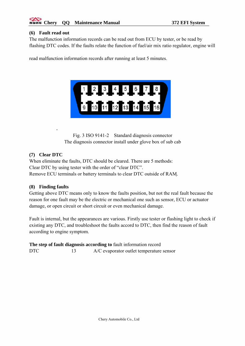
(6) Fault read out The malfunction information records can be read out from ECU by tester, or be read by flashing DTC codes. If the faults relate the function of fuel/air mix ratio regulator, engine will read malfunction information records after running at least 5 minutes.
Fig. 3 ISO 9141-2 Standard diagnosis connector
The diagnosis connector install under glove box of sub cab
(7) Clear DTC When eliminate the faults, DTC should be cleared. There are 5 methods: Clear DTC by using tester with the order of “clear DTC”. Remove ECU terminals or battery terminals to clear DTC outside of RAM. (8) Finding faults Getting above DTC means only to know the faults position, but not the real fault because the reason for one fault may be the electric or mechanical one such as sensor, ECU or actuator damage, or open circuit or short circuit or even mechanical damage. Fault is internal, but the appearances are various. Firstly use tester or flashing light to check if existing any DTC, and troubleshoot the faults accord to DTC, then find the reason of fault according to engine symptom. The step of fault diagnosis according to fault information record DTC 13 A/C evaporator outlet temperature sensor
Chery Automobile Co., Ltd

Chery QQ Maintenance Manual 372 EFI System
The diagram for A/C evaporator temperature sensor
No. Operation steps Test
results
Next step
1 Turn on ignition key. Next
Yes Next 2 Pull out connector of A/C evaporator
temperature sensor, measure if the volt
between 2 pins is 5V with multimeter.
No 4
Yes Replace sensor 3 Check any open or short between 2 pins
with multimeter.
No Replace ECU
Yes Repair or replace
harness
4 ECU and harness, check any open or short
between pin 30 , 39 of ECU and pin (1) and
(2) of sensor with multimeter. No Replace ECU
Chery Automobile Co., Ltd

Chery QQ Maintenance Manual 372 EFI System
DTC 14 TPS
The diagram of TPS
No. Operation steps
1 Turn on ignition key. 2 Pull out connector of A/C evaporator
temperature sensor, measure if the volt between 2 pins is 5V with multimeter.
3 Measure the resistance between pin (1) and (2) if in 1.6 to 2.4k with multimeter.
4 Run slowly TPS from one end to another and check any open or short between pin (1) and (3).
5 Connect adaptor between ECU and harness, check any open or short between pin 12 , 30 of ECU and pin (1) and (2) of sensor with multimeter.
KS
Chery Automobile Co., Ltd
Test results
Next step
Next Yes Next
No
5
Yes Next
No Replace sensor
Yes Replace sensor
No Replace ECU
Yes Repair or replace harness
No Replace ECU
Chery QQ Maintenance Manual 372 EFI System
爆震传感器
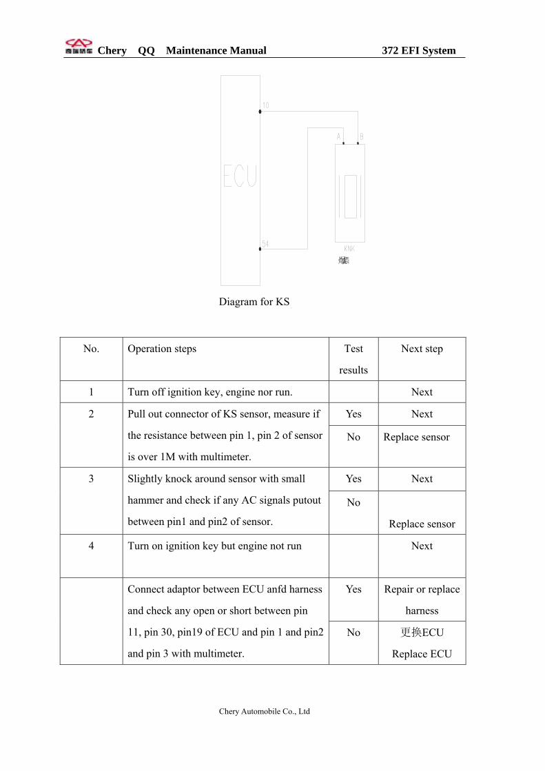
Diagram for KS
No. Operation steps Test
results
Next step
1 Turn off ignition key, engine nor run. Next
Yes Next 2 Pull out connector of KS sensor, measure if
the resistance between pin 1, pin 2 of sensor
is over 1M with multimeter.
No Replace sensor
Yes Next 3 Slightly knock around sensor with small
hammer and check if any AC signals putout
between pin1 and pin2 of sensor.
No
Replace sensor
4 Turn on ignition key but engine not run Next
Yes Repair or replace
harness
Connect adaptor between ECU anfd harness
and check any open or short between pin
11, pin 30, pin19 of ECU and pin 1 and pin2
and pin 3 with multimeter.
No 更换ECU
Replace ECU
Chery Automobile Co., Ltd
Chery QQ Maintenance Manual 372 EFI System
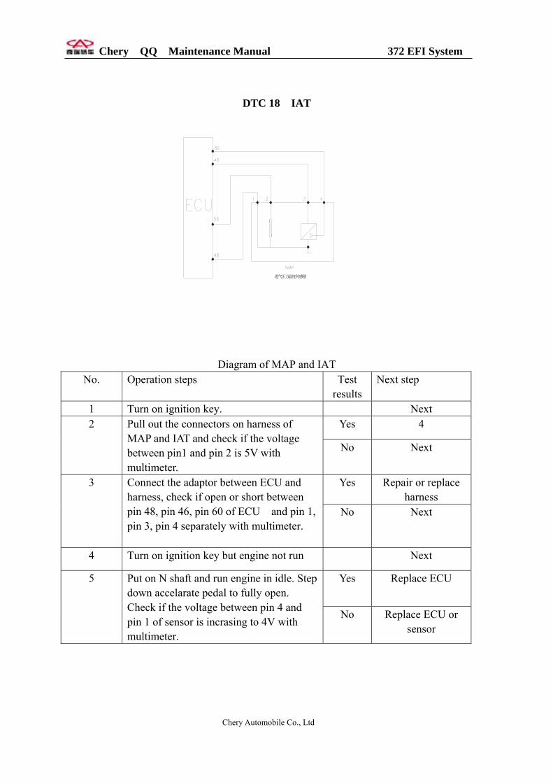
DTC 18 IAT
进气压力温度传感器
Diagram of MAP and IAT No. Operation steps Test
results Next step
1 Turn on ignition key. Next Yes 4 2 Pull out the connectors on harness of
MAP and IAT and check if the voltage between pin1 and pin 2 is 5V with multimeter.
No Next
Yes Repair or replace harness
3 Connect the adaptor between ECU and harness, check if open or short between pin 48, pin 46, pin 60 of ECU and pin 1, pin 3, pin 4 separately with multimeter.
No Next
4 Turn on ignition key but engine not run Next
Yes Replace ECU
5 Put on N shaft and run engine in idle. Step down accelarate pedal to fully open. Check if the voltage between pin 4 and pin 1 of sensor is incrasing to 4V with multimeter.
No Replace ECU or sensor
Chery Automobile Co., Ltd

Chery QQ Maintenance Manual 372 EFI System
Oxygen sensor
主继电器
氧传感器
The diagram of oxygen sensor No. Operation steps Test
result 1 Turn on ignition key.
Yes 2 Put out the connector on oxygen sensor and check if the voltage between pin 1 and pin 2 is 12 V.
No Yes 3 Check if the resistance between pin 1 and pin 2 on
oxygen sensor is from 6 to 25. No Yes 4 Check if the fuse in oxygen sensor heating circuit
is burn out. No Yes R5 Check if open or short between pin 1 on sensor
and pin 87 on fuel pump relay, check open or short between pin 2 and pin 59. No
6 Insert the connector of oxygen sensor harness. Put N shaft and run engine in idle to normal coolant temperature.
Yes 7 Put out the connectors of oxygen sensor from harness. Check if output 0.1-0.9V voltage between pin 4(+) and pin 3(-) Yes
Yes R8 Connect the adaptor between ECU and harness. Check if open or short between pin 43, pin 59 on ECU and pin 3, pin 4 separately No
Oxygen sensor
Chery Automobile Co., Ltd
Next step
Next Next
4 Replace ECU
Replace sensor Replace fuse
Next epair or replace
harness
Next
Next
Next
Repalce sensor
epair or replace harness
更换 Replace ECU

Chery QQ Maintenance Manual 372 EFI System
DTC 18 IAT
进气压力温度传感器
The diagram of MAP and IAT
No. Operation Steps Test
result
Next step
1 Turn on ignition key. Next
Yes Next 2 Put out the connectors on MAP and IAT
harness.Check if the voltage between pin 1
and pin 2 is 5 V.
No 4
Yes Replace ECU 3 Check if the resistance between pin 1 and
pin 2 is suit to the temperature ( see related
parts in this manual).
No Replace sensor
Yes Repair or replace
harness
4 Connect the adaptor between ECU and
harness. Check if open or short between pin
30, pin 12, pin 44 on ECU and pin 1, pin 3,
pin 2 separately.
No Replace ECU
Coolant temperature sensor
Chery Automobile Co., Ltd

Chery QQ Maintenance Manual 372 EFI System
接仪表
b
The diagram of CTS
No. Operation steps Test
result
Next step
1 Turn on ignition key. Next
Yes Next 2 Put out the connector on CTS harness,
check if the voltage between pin and pin c is
5V.
No 4
Yes Replace ECU 3 Check if the resistance between pin a and
pin c is suit to the temperature ( see related
parts in this manual).
No Replace sensor
Yes Repair or replace
harness
4 Connect the adaptor between ECU and
harness. Check if open or short between pin
73, pin 31 on ECU and pin a, pin c
separately.
No Replace ECU
Injector
Chery Automobile Co., Ltd
Chery QQ Maintenance Manual 372 EFI System
主继电器
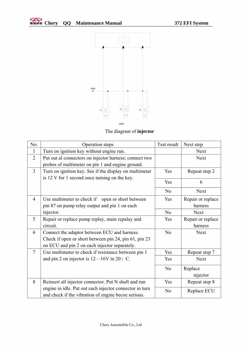
缸 缸 缸
喷油器组 The diagram of injector
No. Operation steps Test result Next step 1 Turn on ignition key without engine run. Next 2 Put out al connectors on injector harness; connect two
probes of multimeter on pin 1 and engine ground. Next
Yes Repeat step 2
Yes 6
3 Turn on ignition key. See if the display on multimeter is 12 V for 1 second once turning on the key.
No Next Yes Repair or replace
harness 4 Use multimeter to check if open or short between
pin 87 on pump relay output and pin 1 on each injector. No Next
5 Repair or replace pump replay, main repalay and circuit.
Yes Repair or replace harness
6 Connect the adaptor between ECU and harness. Check if open or short between pin 24, pin 61, pin 23 on ECU and pin 2 on each injector separately.
No Next
Yes Repeat step 7 Yes Next
7 Use multimeter to check if resistance between pin 1 and pin 2 on injector is 12—16V in 20 C . No Replace
injector Yes Repeat step 8 8 Reinsert all injector connector. Put N shaft and run
engine in idle. Put out each injector connector in turn and check if the vibration of engine becoe serious.
No Replace ECU
Chery Automobile Co., Ltd

Chery QQ Maintenance Manual 372 EFI System
Canistor control driver
Diagram of canistor control valve
No. Operation steps Test
result
Next step 1 Run engine in idle to normal coolant
temperature. Next
Yes Next 2 Put out the connector on canistor valve and check if the voltage between two pins is 12 V.
No 5(Check live wire)
Yes Next 3 Reinsert conncetor of canistor valve harness. Run engine to 1500 RPM. Touch valve with hand and check if any slightly viabration or impact on valve.
No 7(Check ground wire)
Yes ReplaceECU 4 Use multimeter to check if resistance between pin 1 and pin 2 is 22—30.
No Replace canister control valve
Yes Repair or replace harness
5 Use multimeter to check if open or short between pin 87 on main relay and pin 1 on valve. No Next
6 Repair or replace main relay and circuit.
Yes Repair or replace harness
7 Shut off engine. Connect adaptor between ECU and harness. Use multimeter to check if open or short between pin 26 on ECU and pin 2 on valve.
No Replace ECU
Chery Automobile Co., Ltd

Chery QQ Maintenance Manual 372 EFI System
MIL driver
The diagram of MIL
NO. Operation steps Test result
Next step
1 Turn on ignition key Next Yes Next 2 Remove instrument panel. Put out MIL
bulb. Use multimeter to check if the voltage in MIL socket is 12 V.
No 5(Check live wire)
Yes Next 3 Use multimeter to check if MIL bulb is good. No Replace bulb.
Yes Repair or replace harness
4 Connect the adaptor between ECU and harness. Check if open or short between pin 70 on ECU and input connector of MIL. No Replace ECU
Yes Replace fuse 5 Check if the fuse in oxygen heating circuit is burn out. No Next
Yes Repair or replace harness
6 Use multimeter to check if open or short between pin 87 on main relay and pin 1 on MIL socket. No Next
7 Repair or replace main relay and circuit.
Chery Automobile Co., Ltd
Chery QQ Maintenance Manual 372 EFI System
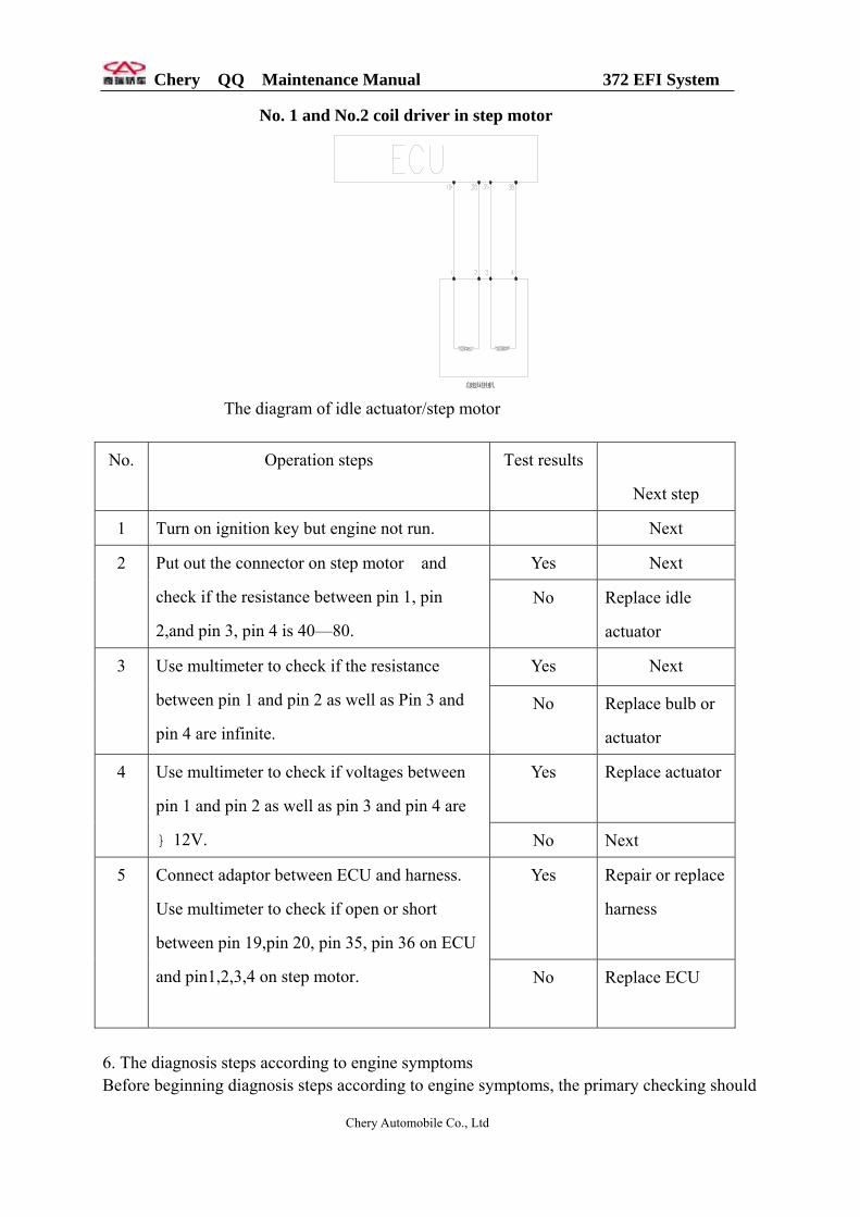
No. 1 and No.2 coil driver in step motor
怠速步进电机 The diagram of idle actuator/step motor
No. Operation steps Test results
Next step
1 Turn on ignition key but engine not run. Next
Yes Next 2 Put out the connector on step motor and
check if the resistance between pin 1, pin
2,and pin 3, pin 4 is 40—80.
No Replace idle
actuator
Yes Next 3 Use multimeter to check if the resistance
between pin 1 and pin 2 as well as Pin 3 and
pin 4 are infinite.
No Replace bulb or
actuator
Yes Replace actuator
4 Use multimeter to check if voltages between
pin 1 and pin 2 as well as pin 3 and pin 4 are
12V . No Next
Yes Repair or replace
harness
5 Connect adaptor between ECU and harness.
Use multimeter to check if open or short
between pin 19,pin 20, pin 35, pin 36 on ECU
and pin1,2,3,4 on step motor. No Replace ECU
6. The diagnosis steps according to engine symptoms Before beginning diagnosis steps according to engine symptoms, the primary checking should
Chery Automobile Co., Ltd

Chery QQ Maintenance Manual 372 EFI System
be carried out: (1) Make any abnormal situation for ECU and MIL (except vehicle without MIL). (2) Use diagnoses instrument or flashlight to check to insure no any malfunction information
records. (3) Use diagnoses instrument to check the idle data on heated engine of EFI system to insure
everything is OK. (4) Make sure the sysptoms that driver told exisist and check the exact position of sysptom.
Then begin appearance check: Check if clear or substance on harness ground. Check if any break, tweast in vaccum pipe or if connect correctly. Check if any block in vaccum pipe. Check if any stave or damage on intake air pipe. Check if the seal between throttle body and manifold is good. Check if any break, aging on high voltage line in ignition system or connect correctly. Check if the connection of wires is correct or any loose/bad contact on connector. 1) Engine does not run or run slowly on startin No. Operation steps Test step Next step
Yes Next 1 Check if the voltage between two poles on battery is 10—12.5 V. No Repair or replace battery
Yes Next 2 Turn on ignition key. Check if the voltage on positive poles of battery connected with the key is 10—12.5 V.
No Repair poles or replace wires
Yes Next 3 Keep ignition key on start position. Check if the voltage on positive pole of stater connected with ignition key is 8V.
No Replace bulb, replace actuator, repair or replace ignition key
Yes Next 4 Keep ignition key on start position. Check if the voltage on positive pole of stater is 8V.
No Repair poles or replace wires
Yes Repair or replace start motor
5 Use multimeter to check if open or short for starter.
No Next
Yes Trouble shooting 6 Check if engine blocks for bad lubrication. No Next
Yes Replace suitable oil 7 If in winter, check if the resistance of starter is too big that resulted by wrong lubricant or gear oil.
No Repair or replace timing belt
2)Engine can run but cannot start successfully (with distributor) No. Operation steps Check step Next step
Chery Automobile Co., Ltd
Chery QQ Maintenance Manual 372 EFI System
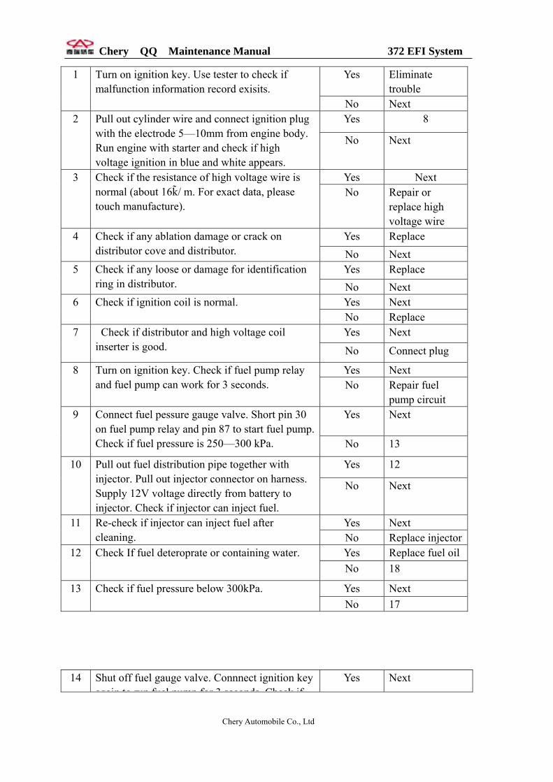
Yes Eliminate trouble
1 Turn on ignition key. Use tester to check if malfunction information record exisits.
No Next Yes 8 2 Pull out cylinder wire and connect ignition plug
with the electrode 5—10mm from engine body. Run engine with starter and check if high voltage ignition in blue and white appears.
No Next
Yes Next 3 Check if the resistance of high voltage wire is normal (about 16k / m. For exact data, please touch manufacture).
No Repair or replace high voltage wire
Yes Replace 4 Check if any ablation damage or crack on distributor cove and distributor. No Next
Yes Replace 5 Check if any loose or damage for identification ring in distributor. No Next
Yes Next 6 Check if ignition coil is normal. No Replace
Yes Next 7 Check if distributor and high voltage coil inserter is good. No Connect plug
Yes Next 8 Turn on ignition key. Check if fuel pump relay and fuel pump can work for 3 seconds. No Repair fuel
pump circuit Yes Next 9 Connect fuel pessure gauge valve. Short pin 30
on fuel pump relay and pin 87 to start fuel pump. Check if fuel pressure is 250—300 kPa. No 13
Yes 12 10 Pull out fuel distribution pipe together with injector. Pull out injector connector on harness. Supply 12V voltage directly from battery to injector. Check if injector can inject fuel.
No Next
Yes Next 11 Re-check if injector can inject fuel after cleaning. No Replace injector
Yes Replace fuel oil12 Check If fuel deteroprate or containing water. No 18
Yes Next 13 Check if fuel pressure below 300kPa. No 17
14 Shut off fuel gauge valve. Connnect ignition key
again to run fuel pump for 3 seconds Check ifYes Next
Chery Automobile Co., Ltd
Chery QQ Maintenance Manual 372 EFI System
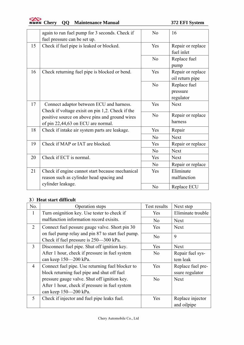
again to run fuel pump for 3 seconds. Check if fuel pressure can be set up.
No 16
Yes Repair or replace fuel inlet
15 Check if fuel pipe is leaked or blocked.
No Replace fuel pump
Yes Repair or replace oil return pipe
16 Check returning fuel pipe is blocked or bend.
No Replace fuel pressure regulator
Yes Next 17 Connect adaptor between ECU and harness. Check if voltage exisit on pin 1,2. Check if the positive source on above pins and ground wires of pin 22,44,63 on ECU are normal.
No Repair or replace harness
Yes Repair 18 Check if intake air system parts are leakage. No Next Yes Repair or replace19 Check if MAP or IAT are blocked. No Next Yes Next 20 Check if ECT is normal. No Repair or replaceYes Eliminate
malfunction 21 Check if engine cannot start because mechanical
reason such as cylinder head spacing and cylinder leakage. No Replace ECU
3)Heat start difficult No. Operation steps Test results Next step
Yes Eliminate trouble1 Turn onignition key. Use tester to check if malfunction information record exisits. No Next
Yes Next 2 Connect fuel pessure gauge valve. Short pin 30 on fuel pump relay and pin 87 to start fuel pump. Check if fuel pressure is 250—300 kPa.
No 9
Yes Next 3 Disconnect fuel pipe. Shut off ignition key. After 1 hour, check if pressure in fuel system can keep 150—200 kPa.
No Repair fuel sys- tem leak
Yes Replace fuel pre-ssure regulator
4 Connect fuel pipe. Use returning fuel blocker to block returning fuel pipe and shut off fuel pressure gauge valve. Shut off ignition key. After 1 hour, check if pressure in fuel system can keep 150—200 kPa.
No Next
5 Check if injector and fuel pipe leaks fuel. Yes Replace injector and oilpipe
Chery Automobile Co., Ltd

Chery QQ Maintenance Manual 372 EFI System
No Next Yes Check coolant
temperature and circuit
6 Pull out water temperature sensor connector and run engine. Check if engine can start.
No Next Yes Next 7 Connect adaptor between ECU and harness.
Check if voltage exisit on pin 1,2. Check if the positive source on above pins and ground wires of pin 22,44,63 on ECU are normal.
No Repair or replace harness
Yes Harness 8 Replace fuel and heat start engine again. Check if engine can start. No Replace ECU
Yes Next 9 Check if fuel pipe blocked or bend, or if fuel pump regulator can work normally. No Repair or replace
Yes Next 10 Use multimeter tocheck if voltages between two ends of fuel pump inserter exists. No Repair or replace
fuel pump relay and leading line
Yes Next 11 Check if fuel pump resistance is correct. No Replace fuel
pump Yes Replace fuel
pump 12
Check if fuel pump blocked. No Replace ECU
4)RPM is normal but difficult in starting No. Operation steps Test results Next step
Yes Eliminate malfunction
1 Turn on ignition key. Use tester to check if malfunction information record exists.
No Next Yes Next 2 Check if air filter is through. No Replace Yes Next 3 Check if MAP pressure is 35—65 kPa in idle
after start. No Eliminate intake system leak
4 Step down throttle slightly and check engine can start easily.
Yes Replace or check throttle valve and idle pass
Yes Next 5 Connect fuel pressure gauge valve. Short pin 30 on fuel pump relay and pin 87 to start fuel pump. Check if fuel pressure is 250—300 kPa.
No 9
6 Yes 8
Chery Automobile Co., Ltd

Chery QQ Maintenance Manual 372 EFI System
Use special connector to supply 12 V voltage from battery to injector and check if injector works normally.
No Next
Yes Next 7 Re-check if injector can inject fuel after cleaning. No Replace injector
Yes Replace fuel 8 Replace fuel. Check If fuel deteriorate or containing water. No 14
Yes Next 9 Check if fuel pressure below 250kPa. No 13 Yes Next 10 Shut off fuel gauge valve. Connect ignition key
again to run fuel pump for 3 seconds. Check if fuel pressure can be set up.
No 12
Yes Replace fuel pressure regulator
11 Open fuel gauge valve, use return fuel blocker to clamp fuel pipe for no returning fuel. Check if fuel pressure can be set up soon.
No Repair and replace injector or fuel pipe
Yes Repair and replace fuel pipe
12 Connect fuel pessure gauge valve. Short pin 30 on fuel pump relay and pin 87 to start fuel pump. Check if fuel pressure is 250—300 kPa No Replace fuel
pump Yes Repair or replace
returning fuel pipe
13 Check returning fuel pipe is blocked or bend.
No Replace fuel prassure regulator
Yes Next 14 Pull out idle actuator connector before coolant temperature reaches 35 C and check if engine speed is dropping.
No Repair or replace idle actuator
Yes Next 15 Turn on ignition key. Check voltages on following pins are normal: 12 V for pin 27 and zreo for pin 14 and 19.
No Check harness or connector
Yes Next 16 Run engine in idle. When coolant temperature reaches normal, ground pin 51 and check if ignition advance angle is 6.75 crank angle.
No Adjust ignition advance angle
Yes Next 17 Check if cylinder compressed pressure is normal. No Trouble shooting
18 Yes Repair or replace
Chery Automobile Co., Ltd
Chery QQ Maintenance Manual 372 EFI System
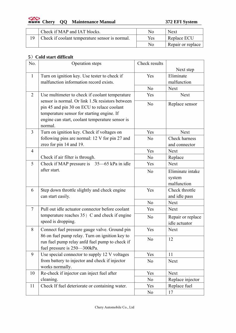
Check if MAP and IAT blocks. No Next Yes Replace ECU 19 Check if coolant temperature sensor is normal. No Repair or replace
5)Cold start difficult No. Operation steps Check results
Next step Yes Eliminate
malfunction 1 Turn on ignition key. Use tester to check if
malfunction information record exists. No Next Yes Next 2 Use multimeter to check if coolant temperature
sensor is normal. Or link 1.5k resistors between pin 45 and pin 30 on ECU to relace coolant temperature sensor for starting engine. If engine can start, coolant temperature sensor is normal.
No Replace sensor
Yes Next 3 Turn on ignition key. Check if voltages on following pins are normal: 12 V for pin 27 and zreo for pin 14 and 19.
No Check harness and connector
Yes Next 4 Check if air filter is through. No Replace
Yes Next 5 Check if MAP pressure is 35—65 kPa in idle after start.
No Eliminate intake system malfunction
Yes Check throttle and idle pass
6
Step down throttle slightly and check engine can start easily.
No Next Yes Next 7 Pull out idle actuator connector before coolant
temperature reaches 35 C and check if engine speed is dropping.
No Repair or replace idle actuator
Yes Next 8 Connect fuel pressure gauge valve. Ground pin 86 on fuel pump relay. Turn on ignition key to run fuel pump relay anfd fuel pump to check if fuel pressure is 250—300kPa.
No 12
Yes 11 9 Use special connector to supply 12 V voltages from battery to injector and check if injector works normally.
No Next
Yes Next 10 Re-check if injector can inject fuel after cleaning. No Replace injector
Yes Replace fuel 11 Check If fuel deteriorate or containing water. No 17
Chery Automobile Co., Ltd
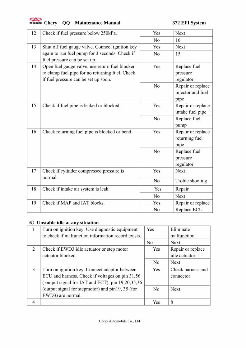
Chery QQ Maintenance Manual 372 EFI System
Yes Next 12 Check if fuel pressure below 250kPa. No 16 Yes Next 13 Shut off fuel gauge valve. Connect ignition key
again to run fuel pump for 3 seconds. Check if fuel pressure can be set up.
No 15
Yes Replace fuel pressure regulator
14 Open fuel gauge valve, use return fuel blocker to clamp fuel pipe for no returning fuel. Check if fuel pressure can be set up soon.
No Repair or replace injector and fuel pipe
Yes Repair or replace intake fuel pipe
15 Check if fuel pipe is leaked or blocked.
No Replace fuel pump
Yes Repair or replace returning fuel pipe
16 Check returning fuel pipe is blocked or bend.
No Replace fuel pressure regulator
Yes Next 17 Check if cylinder compressed pressure is normal.
No Troble shooting
Yes Repair 18 Check if intake air system is leak. No Next Yes Repair or replace19 Check if MAP and IAT blocks. No Replace ECU
6)Unstable idle at any situation
Yes Eliminate malfunction
1 Turn on ignition key. Use diagnostic equipment to check if malfunction information record exists.
No Next Yes Repair or replace
idle actuator 2 Check if EWD3 idle actuator or step motor
actuator blocked. No Next Yes Check harness and
connector
3 Turn on ignition key. Connect adaptor between ECU and harness. Check if voltages on pin 31,56 ( output signal for IAT and ECT), pin 19,20,35,36 (output signal for stepmotor) and pin19, 35 (for EWD3) are normal.
No Next
4 Yes 8
Chery Automobile Co., Ltd
Chery QQ Maintenance Manual 372 EFI System
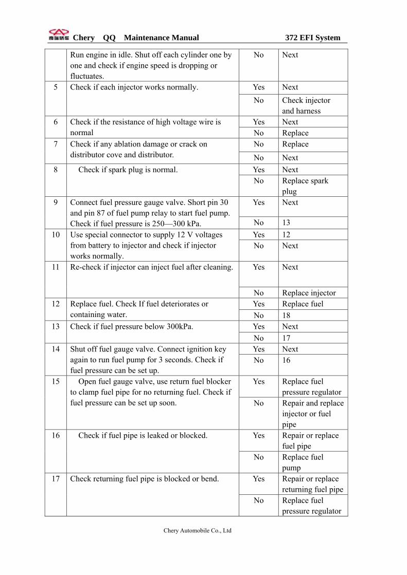
Run engine in idle. Shut off each cylinder one by one and check if engine speed is dropping or fluctuates.
No Next
Yes Next 5 Check if each injector works normally. No Check injector
and harness Yes Next 6 Check if the resistance of high voltage wire is
normal No Replace No Replace 7 Check if any ablation damage or crack on
distributor cove and distributor. No Next Yes Next 8 Check if spark plug is normal. No Replace spark
plug Yes Next 9 Connect fuel pressure gauge valve. Short pin 30
and pin 87 of fuel pump relay to start fuel pump. Check if fuel pressure is 250—300 kPa. No 13
Yes 12 10 Use special connector to supply 12 V voltages from battery to injector and check if injector works normally.
No Next
Yes Next 11 Re-check if injector can inject fuel after cleaning.
No Replace injector Yes Replace fuel 12 Replace fuel. Check If fuel deteriorates or
containing water. No 18 Yes Next 13 Check if fuel pressure below 300kPa. No 17 Yes Next 14 Shut off fuel gauge valve. Connect ignition key
again to run fuel pump for 3 seconds. Check if fuel pressure can be set up.
No 16
Yes Replace fuel pressure regulator
15 Open fuel gauge valve, use return fuel blocker to clamp fuel pipe for no returning fuel. Check if fuel pressure can be set up soon. No Repair and replace
injector or fuel pipe
Yes Repair or replace fuel pipe
16 Check if fuel pipe is leaked or blocked.
No Replace fuel pump
Yes Repair or replace returning fuel pipe
17 Check returning fuel pipe is blocked or bend.
No Replace fuel pressure regulator
Chery Automobile Co., Ltd

Chery QQ Maintenance Manual 372 EFI System
Yes Cleaning 18 Check if sensor holes on MAP and IAT block. No Next Yes Next 19 Run engine in idle. After coolant temperature
reaches actuating temperature for closed loop control, check if oxygen sensor works normally.
No Check oxygen sensor and harness
Yes Eliminate leak 20
Chec if intake air system leaks. No Next
Yes Next 21 Check if cylinder pressure is normal. No Trouble shooting
7) Unstable idle at heat engine
Yes Eliminate malfunction
1 Turn on ignition key. Use diagnostic equipment to check if malfunction information record exists.
No Next Yes Next 2 Check if air filter is through.
No Replace Yes Next
3 Check if MAP pressure is 35—65 kPa at idle in
heating engine process. No Eliminate intake
system malfunction
Yes Next 4 Shut off engine ,turn on ignition key. Connect adaptor between ECU and harness. Check if voltages on pin 31,56 ( output signal for IAT and ECT) is normal.
No Check
Yes Next 5 Pull out idle actuator connector before heat engine finish and check if engine speed is normal No Replace idle
actuator Yes Next 6 Check if coolant temperatuer sensor is normal No Replace
Chery Automobile Co., Ltd
Chery QQ Maintenance Manual 372 EFI System
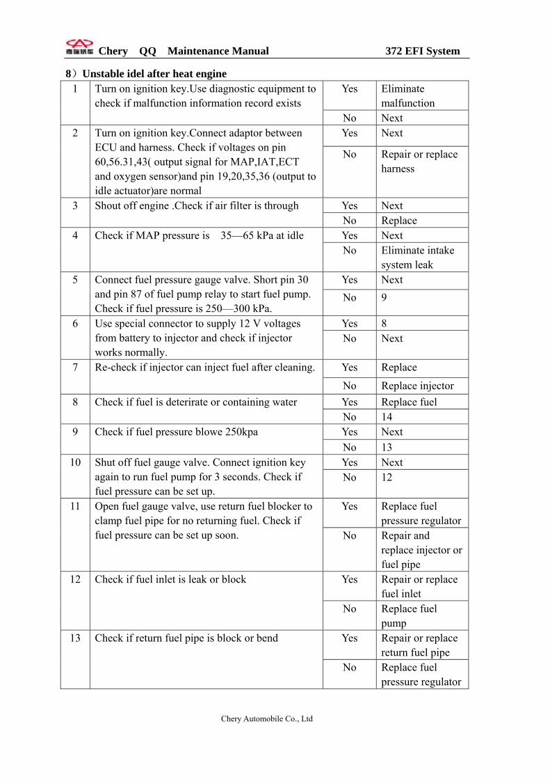
8)Unstable idel after heat engine Yes Eliminate
malfunction 1 Turn on ignition key.Use diagnostic equipment to
check if malfunction information record exists No Next Yes Next 2 Turn on ignition key.Connect adaptor between
ECU and harness. Check if voltages on pin 60,56.31,43( output signal for MAP,IAT,ECT and oxygen sensor)and pin 19,20,35,36 (output to idle actuator)are normal
No Repair or replace harness
Yes Next 3 Shout off engine .Check if air filter is through No Replace Yes Next 4 Check if MAP pressure is 35—65 kPa at idle No Eliminate intake
system leak Yes Next 5 Connect fuel pressure gauge valve. Short pin 30
and pin 87 of fuel pump relay to start fuel pump. Check if fuel pressure is 250—300 kPa.
No 9
Yes 8 6 Use special connector to supply 12 V voltages from battery to injector and check if injector works normally.
No Next
Yes Replace 7 Re-check if injector can inject fuel after cleaning.
No Replace injector Yes Replace fuel 8 Check if fuel is deterirate or containing water No 14 Yes Next 9 Check if fuel pressure blowe 250kpa No 13 Yes Next 10 Shut off fuel gauge valve. Connect ignition key
again to run fuel pump for 3 seconds. Check if fuel pressure can be set up.
No 12
Yes Replace fuel pressure regulator
11 Open fuel gauge valve, use return fuel blocker to clamp fuel pipe for no returning fuel. Check if fuel pressure can be set up soon. No Repair and
replace injector or fuel pipe
Yes Repair or replace fuel inlet
12 Check if fuel inlet is leak or block
No Replace fuel pump
Yes Repair or replace return fuel pipe
13 Check if return fuel pipe is block or bend
No Replace fuel pressure regulator
Chery Automobile Co., Ltd

Chery QQ Maintenance Manual 372 EFI System
Yes Replace coolant temperature sensor
14 Pull out coolant temperature sensor and check if engine is normal
No Next Yes Next 15 Check if cylinder compression pressure of engine
is normal No Trouble shooting Yes Next 16 Check if the resistance of high voltage wire is
normal (about 16k / m. For exact data, please touch manufacture).。
No Replace
Yes Replace 17 Check if any ablation damage or crack on distributor cover and distributor No Next
Yes Replace ECU 18 Check if spark plug is normal No Replace spark
plug 9)Unstable idel or switch off
Yes Eliminate malfunction
1 Turn on ignition key.Use diagnostic equipment to check if malfunction information record exists
No Next Yes Next 2 Turn on A/C switch. Turn on ignition
key.Connect adaptor between ECU and harness. Check if pin 50 and 58(A/C switch) have signal input
No Repair A/C circuit
Yes Next 3 Check if A/C system pressure,magnetic clutch of compressor and A/C pump are normal No Repair or replace
Yes Next 4 Turn on ignition key. Check if voltage on pin19,20,35,36(output to idle actuator)are normal No Check control
circuit Yes Repair or replace
stepmotor 5 Remove stepmotor and check if stepmotor is
jamming or does not work flexibly No Next Yes Replace ECU 6 Turn engine and open A/C .Check if idle actuator
is normal No Replace idle actuator
Chery Automobile Co., Ltd
Chery QQ Maintenance Manual 372 EFI System
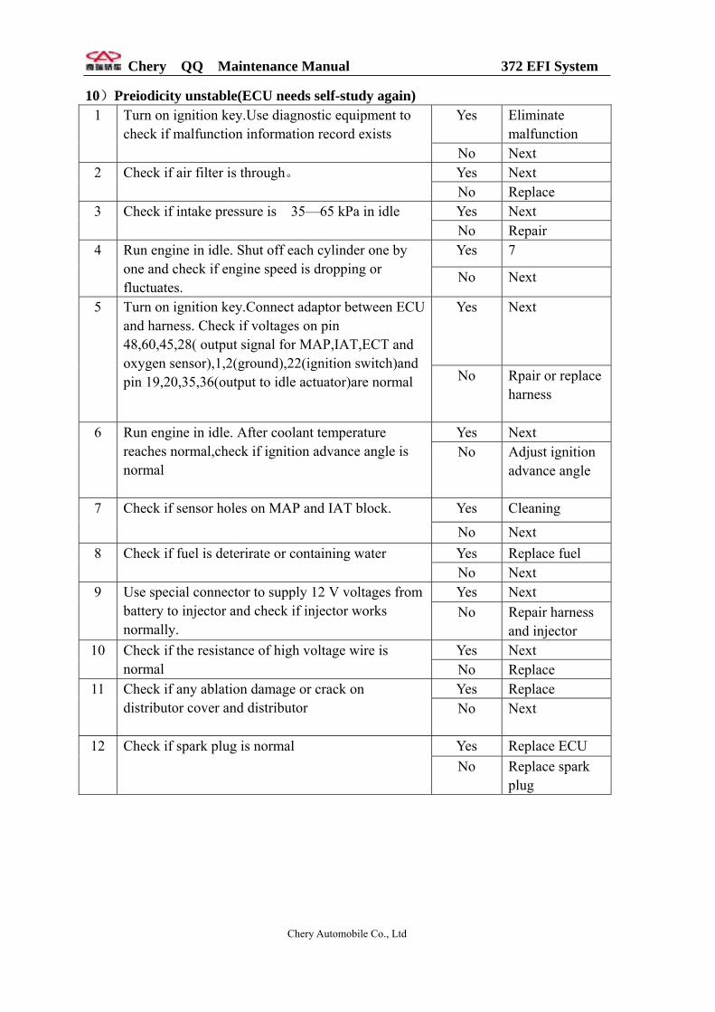
10)Preiodicity unstable(ECU needs self-study again) Yes Eliminate
malfunction 1 Turn on ignition key.Use diagnostic equipment to
check if malfunction information record exists No Next Yes Next 2 Check if air filter is through。
No Replace Yes Next 3 Check if intake pressure is 35—65 kPa in idle No Repair Yes 7 4 Run engine in idle. Shut off each cylinder one by
one and check if engine speed is dropping or fluctuates.
No Next
Yes Next 5 Turn on ignition key.Connect adaptor between ECU and harness. Check if voltages on pin 48,60,45,28( output signal for MAP,IAT,ECT and oxygen sensor),1,2(ground),22(ignition switch)and pin 19,20,35,36(output to idle actuator)are normal
No Rpair or replace harness
Yes Next 6 Run engine in idle. After coolant temperature reaches normal,check if ignition advance angle is normal
No Adjust ignition advance angle
Yes Cleaning 7 Check if sensor holes on MAP and IAT block.
No Next Yes Replace fuel 8 Check if fuel is deterirate or containing water
No Next Yes Next 9 Use special connector to supply 12 V voltages from
battery to injector and check if injector works normally.
No Repair harness and injector
Yes Next 10 Check if the resistance of high voltage wire is normal No Replace
Yes Replace 11 Check if any ablation damage or crack on distributor cover and distributor
No Next
Yes Replace ECU 12 Check if spark plug is normal No Replace spark
plug
Chery Automobile Co., Ltd
Chery QQ Maintenance Manual 372 EFI System
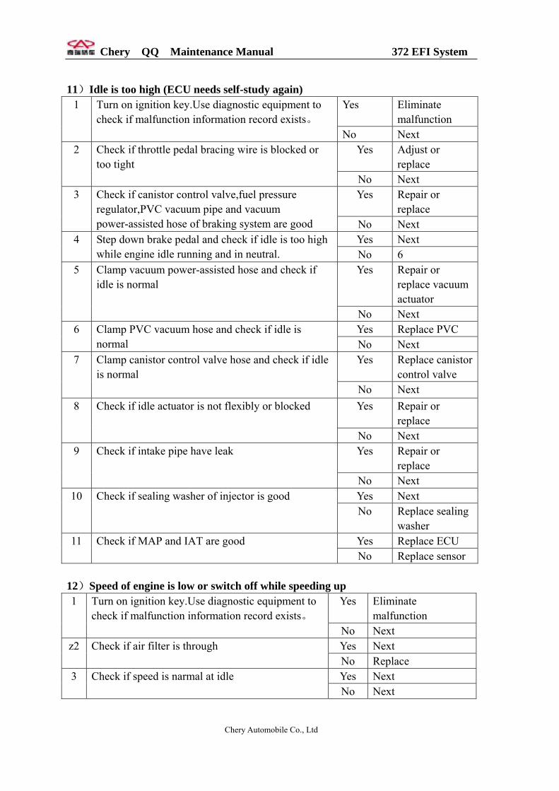
11)Idle is too high (ECU needs self-study again)
Yes Eliminate malfunction
1 Turn on ignition key.Use diagnostic equipment to check if malfunction information record exists。
No Next Yes Adjust or
replace 2 Check if throttle pedal bracing wire is blocked or
too tight No Next
Yes Repair or replace
3 Check if canistor control valve,fuel pressure regulator,PVC vacuum pipe and vacuum power-assisted hose of braking system are good No Next
Yes Next 4 Step down brake pedal and check if idle is too high while engine idle running and in neutral. No 6
Yes Repair or replace vacuum actuator
5 Clamp vacuum power-assisted hose and check if idle is normal
No Next Yes Replace PVC 6 Clamp PVC vacuum hose and check if idle is
normal No Next Yes Replace canistor
control valve 7 Clamp canistor control valve hose and check if idle
is normal No Next Yes Repair or
replace 8 Check if idle actuator is not flexibly or blocked
No Next Yes Repair or
replace 9 Check if intake pipe have leak
No Next Yes Next 10 Check if sealing washer of injector is good No Replace sealing
washer Yes Replace ECU 11 Check if MAP and IAT are good No Replace sensor
12)Speed of engine is low or switch off while speeding up
Yes Eliminate malfunction
1 Turn on ignition key.Use diagnostic equipment to check if malfunction information record exists。
No Next Yes Next z2 Check if air filter is through No Replace Yes Next 3 Check if speed is narmal at idle No Next
Chery Automobile Co., Ltd

Chery QQ Maintenance Manual 372 EFI System
Yes Next 4 Check if intake pressure is 35—65 kPa in idle No Repair Yes Next 5 Run engine in idle. After coolant temperature
reaches normal, check if ignition advance angle is normal
No Adjust ignition advance angle
Yes Next 6 Connect fuel pessure gauge valve. Short pin 30 on fuel pump relay and pin 87 to start fuel pump. Check if fuel pressure is 250—300 kPa
No 10
Yes 9 7 Use special connector to supply 12 V voltages from battery to injector and check if injector works normally.
No Next
Yes Next 8 Re-check if injector can inject fuel after cleaning. No Replace injector
Yes Replace fuel 9 Check if fuel is deterirate or containing water 。 No 15
Yes Next 10 Check if fuel pressure below 250kPa. No 14
Yes Next 11 Shut off fuel gauge valve. Connect ignition key again to run fuel pump for 3 seconds. Check if fuel pressure can be set up.
No 13
Yes Replace fuel pressure regulator
12 Open fuel gauge valve, use return fuel blocker to clamp fuel pipe for no returning fuel. Check if fuel pressure can be set up soon。
No Replace and repair injector or fuel pipe
Yes Repair or replace fuel inlet
13 Check if fuel pipe is leaked or blocked.
No Replace fuel pump
Yes Repair or replace returning fuel pipe
14 Check returning fuel pipe is blocked or bend.
No Replace fuel pressure regulator
Yes Next 15 Turn on ignition key. Connect adaptor between ECU and harness. Check if voltages on pin 32( output signal for TPS) ,pin 38 (ground connection)and pin 45( for 4.5-5V power of sensor) are normal.
No Repair or replace harness
Yes Replace ECU 16 Check if ignition coil,distrbutor,high voltage wire and spark plug are normal No Repair or replace
relate unit
Chery Automobile Co., Ltd

Chery QQ Maintenance Manual 372 EFI System
13)Speeding up is slow Yes Eliminate malfunction 1 Turn on ignition key.Use diagnostic equipment to
check if malfunction information record exists No Next Yes Next 2 Shout off engine .Check if air filter is through No Replace Yes Next 3 Check if speed is narmal in idle No Refer to trouble
shooting of idle systemYes Next 4 Check if intake pressure is 35—65 kPa in idle No Repair Yes Next 5 Turn on ignition key. Connect adaptor between
ECU and harness. Check if voltages on pin 32( output signal for TPS) ,pin38 (ground connection)and pin 45( 4.5-5V power for sensor) are normal.
No Repair or replace
Yes Next 6 Run engine in idle. After coolant temperature reaches normal, check if ignition advance angle is normal
No Adjust ignition advance angle
Yes Next 7 Connect fuel pessure gauge valve. Short pin 30 on fuel pump relay and pin 87 to start fuel pump. Check if fuel pressure is 250—300 kPa
No 11
Yes 10 8 Use special connector to supply 12 V voltages from battery to injector and check if injector works normally.
No Next
Yes Next 9 Re-check if injector can inject fuel after cleaning. No Replace injector
Yes Replace fuel 10 Check if fuel is deterirate or containing water No 16
Yes Next 11 Check if fuel pressure below 250kPa. No 15
Yes Next 12 Shut off fuel gauge valve. Connect ignition key again to run fuel pump for 3 seconds. Check if fuel pressure can be set up.
No 14
Yes Replace pressure regulator
13 Open fuel gauge valve, use return fuel blocker to clamp fuel pipe for no returning fuel. Check if fuel pressure can be set up soon No Repair and replace
injector or fuel pipe Yes Repair or replace fuel
pipe 14 Check if fuel pipe is leaked or blocked.
No Replace fuel pump
Chery Automobile Co., Ltd
Chery QQ Maintenance Manual 372 EFI System
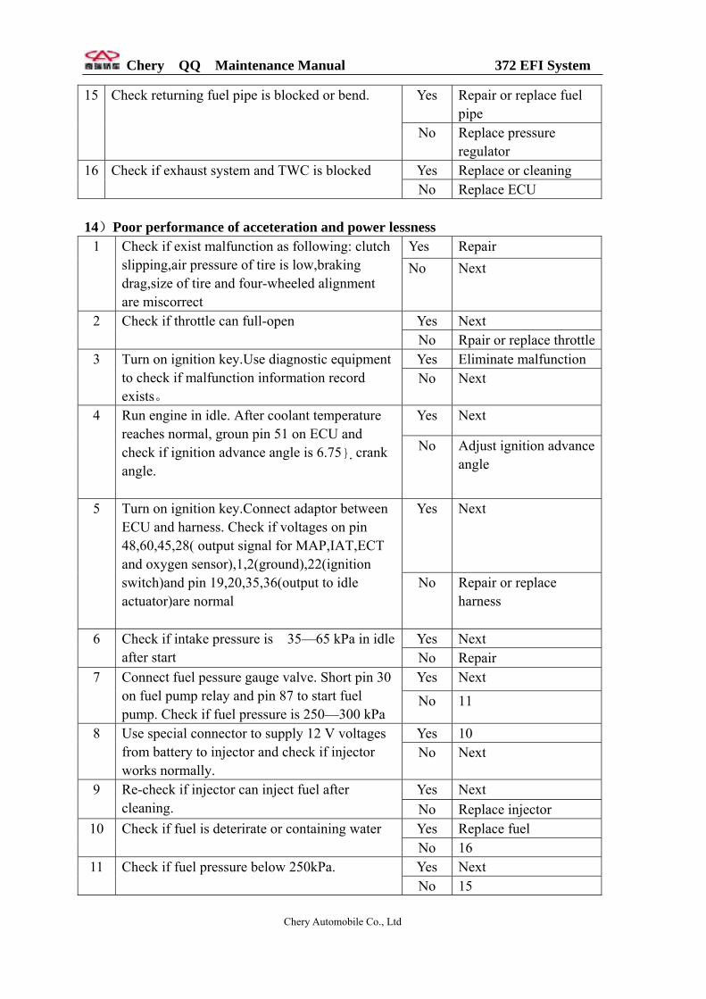
Yes Repair or replace fuel pipe
15 Check returning fuel pipe is blocked or bend.
No Replace pressure regulator
Yes Replace or cleaning 16 Check if exhaust system and TWC is blocked No Replace ECU
14)Poor performance of acceteration and power lessness
Yes Repair 1 Check if exist malfunction as following: clutch slipping,air pressure of tire is low,braking drag,size of tire and four-wheeled alignment are miscorrect
No Next
Yes Next 2 Check if throttle can full-open No Rpair or replace throttle
Yes Eliminate malfunction 3 Turn on ignition key.Use diagnostic equipment to check if malfunction information record exists。
No Next
Yes Next 4 Run engine in idle. After coolant temperature reaches normal, groun pin 51 on ECU and check if ignition advance angle is 6.75 crank angle.
No Adjust ignition advance angle
Yes Next 5 Turn on ignition key.Connect adaptor between ECU and harness. Check if voltages on pin 48,60,45,28( output signal for MAP,IAT,ECT and oxygen sensor),1,2(ground),22(ignition switch)and pin 19,20,35,36(output to idle actuator)are normal
No Repair or replace harness
Yes Next 6 Check if intake pressure is 35—65 kPa in idle after start No Repair
Yes Next 7 Connect fuel pessure gauge valve. Short pin 30 on fuel pump relay and pin 87 to start fuel pump. Check if fuel pressure is 250—300 kPa
No 11
Yes 10 8 Use special connector to supply 12 V voltages from battery to injector and check if injector works normally.
No Next
Yes Next 9 Re-check if injector can inject fuel after cleaning. No Replace injector
Yes Replace fuel 10 Check if fuel is deterirate or containing water No 16 Yes Next 11 Check if fuel pressure below 250kPa.
No 15
Chery Automobile Co., Ltd
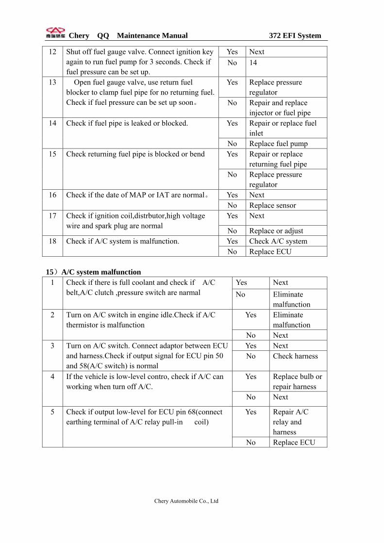
Chery QQ Maintenance Manual 372 EFI System
Yes Next 12 Shut off fuel gauge valve. Connect ignition key again to run fuel pump for 3 seconds. Check if fuel pressure can be set up.
No 14
Yes Replace pressure regulator
13 Open fuel gauge valve, use return fuel blocker to clamp fuel pipe for no returning fuel. Check if fuel pressure can be set up soon。 No Repair and replace
injector or fuel pipe Yes Repair or replace fuel
inlet 14 Check if fuel pipe is leaked or blocked.
No Replace fuel pump Yes Repair or replace
returning fuel pipe 15 Check returning fuel pipe is blocked or bend
No Replace pressure regulator
Yes Next 16 Check if the date of MAP or IAT are normal。 No Replace sensor Yes Next 17
Check if ignition coil,distrbutor,high voltage wire and spark plug are normal No Replace or adjust
Yes Check A/C system 18 Check if A/C system is malfunction. No Replace ECU
15)A/C system malfunction
Yes Next 1 Check if there is full coolant and check if A/C belt,A/C clutch ,pressure switch are narmal No Eliminate
malfunction Yes Eliminate
malfunction 2 Turn on A/C switch in engine idle.Check if A/C
thermistor is malfunction No Next Yes Next 3 Turn on A/C switch. Connect adaptor between ECU
and harness.Check if output signal for ECU pin 50 and 58(A/C switch) is normal
No Check harness
Yes Replace bulb or repair harness
4 If the vehicle is low-level contro, check if A/C can working when turn off A/C.
No Next
Yes Repair A/C relay and harness
5 Check if output low-level for ECU pin 68(connect earthing terminal of A/C relay pull-in coil)
No Replace ECU
Chery Automobile Co., Ltd

Chery QQ Maintenance Manual 372 EFI System
8. Precaution for service 1) Precaution for service EFI (1) Controler removal request Remove controller before welding or painting; Turn off ignition switch when removing controller to void gamage; Don’t remove power wires from battery when engine running or electric appliance is in using; Don’t start engine with high current; Note that the ambient temperature of controller could not exceed 80Cº (2) Clean request: Please observe following regulations: Put removed parts on clean place and cover them with suitable cloth. Only allowed to pull out ot insert each harness or tester harness after ignition switch turns off. Make sure the correction for connecting wires when measuring voltage or ground for electronic control system; Removing power wires from battery or pulling out controller connector will cause losing the information for diagnosis and self-study stored in memory (3) Precaution for fuel system service When removing or installing fuel pump in fully or partial fully fuel tank, pay close attention to: Mounting equipment that could absorb leaked fuel on tank outlet before operation; Avoid skin touch with fuel directly; Cover or block out the opened parts if not be used at once; Take out parts only before installing. Don’t use the parts witout pakage; Don’t damage o-ring during installing injector. Smear a little lubricant on o-ring for beteer fitting; Don’t use compressed air or move vehicle when opening system. 2) Safety precaution In order to avoid personal hurt or damage injector and ignition unit, pay close attentionto: (1) Don’t touch otr pull out ignition harness if engine is running or starting; (2) Pull bout harness connector if engine is started by starter motor (for example in the situation of checking compressed air).
Chery Automobile Co., Ltd