chapter 1 chief architect
TRANSCRIPT
8/4/2019 Chapter 1 Chief Architect
http://slidepdf.com/reader/full/chapter-1-chief-architect 1/54
1
The Chief Architect User Interface
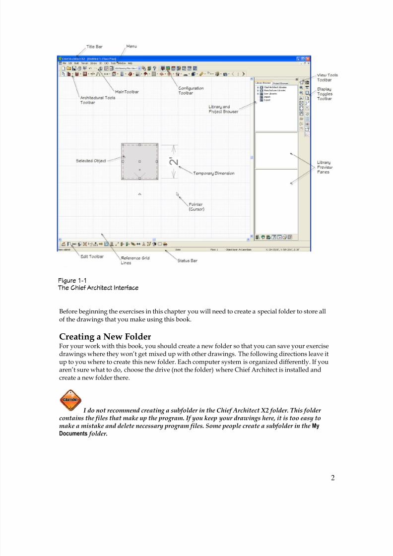
You have installed Chief Architect X2 on your computer. It will looksomething like Figure 1-1. In this first chapter you will get a good look at theinterface of Chief Architect (when I say Chief Architect I’m referring to Chief
Architect X2). You will learn about the different parts, and the differenttoolbars. There will be a section on preferences and defaults. The chapter willinclude everything you will need to know to get set up and get started with theprogram.
In this chapter, you won’t be drawing much of anything. Instead I will beshowing you Chief Architect’s interface. It is important to understand theinterface in Chief Architect because if you understand how the programworks, how it is thinking, what kind of files is it generating, and where it isthat you are storing things, then the process of keeping things straight andworking more effectively with Chief Architect will be easier.
This book is about Chief Architect X2. If you are still using Chief Architect X1or Chief Architect X, you will find that there will be some differences. As youget into this book, you may determine that it may be worth the cost to upgradeto X2. Both X1 and X2 are very good programs once you get used to thechanges that were made from Chief Architect X. There are some things that area little more difficult than in some of the previous versions, not many, but justa couple of things. But generally, overall, all the added features and thefunction make X1 and X2 so much better and easier to use. Just like in any newversion you just have to learn the new things and how to use them.
♦ ♦ ♦
In This Chapter
The Chief Architect UserInterface
Start Up Screen Options
Using the Help Options
Getting Bonus Content
Toolbars and Menus
Hot Keys
♦ ♦ ♦
1CHAPTER
© 2009 Terry Munson, All Rights Reserved.
8/4/2019 Chapter 1 Chief Architect
http://slidepdf.com/reader/full/chapter-1-chief-architect 2/54
2
Before beginning the exercises in this chapter you will need to create a special folder to store allof the drawings that you make using this book.
Creating a New FolderFor your work with this book, you should create a new folder so that you can save your exercisedrawings where they won’t get mixed up with other drawings. The following directions leave itup to you where to create this new folder. Each computer system is organized differently. If youaren’t sure what to do, choose the drive (not the folder) where Chief Architect is installed andcreate a new folder there.
I do not recommend creating a subfolder in the Chief Architect X2 folder. This folder contains the files that make up the program. If you keep your drawings here, it is too easy tomake a mistake and delete necessary program files. Some people create a subfolder in the My
Documents folder.
Figure 1-1 The Chief Architect Interface
8/4/2019 Chapter 1 Chief Architect
http://slidepdf.com/reader/full/chapter-1-chief-architect 3/54
3
STEPS: Creating a new folder
1. Move the mouse cursor down to the bottom of your screen and right-click the Start button.
2. Choose Explore.
3. In the left pane of Windows Explorer, click the drive where you want to create the newfolder. If you don’t know where to create the folder, choose the drive where Chief Architect isinstalled. If you’re on a network, choose the drive that represents your computer.
4. If you want to make a subfolder (a folder within a folder), choose the folder where you wantto create the subfolder.
5. From the Explorer menu, choose File New Folder . A new, highlighted folder, named New
Folder , appears in the right pane. You may have to scroll down to see it.
6. Type Chief Architect Step By Step for the folder name and press ENTER.
Save all drawings that you create for this book in your Chief Architect Step By Step folder.
Creating a folder for your drawings as described in the previous steps is essential beforeyou go on to exercises in the rest of this book.
Start Up Screen Options
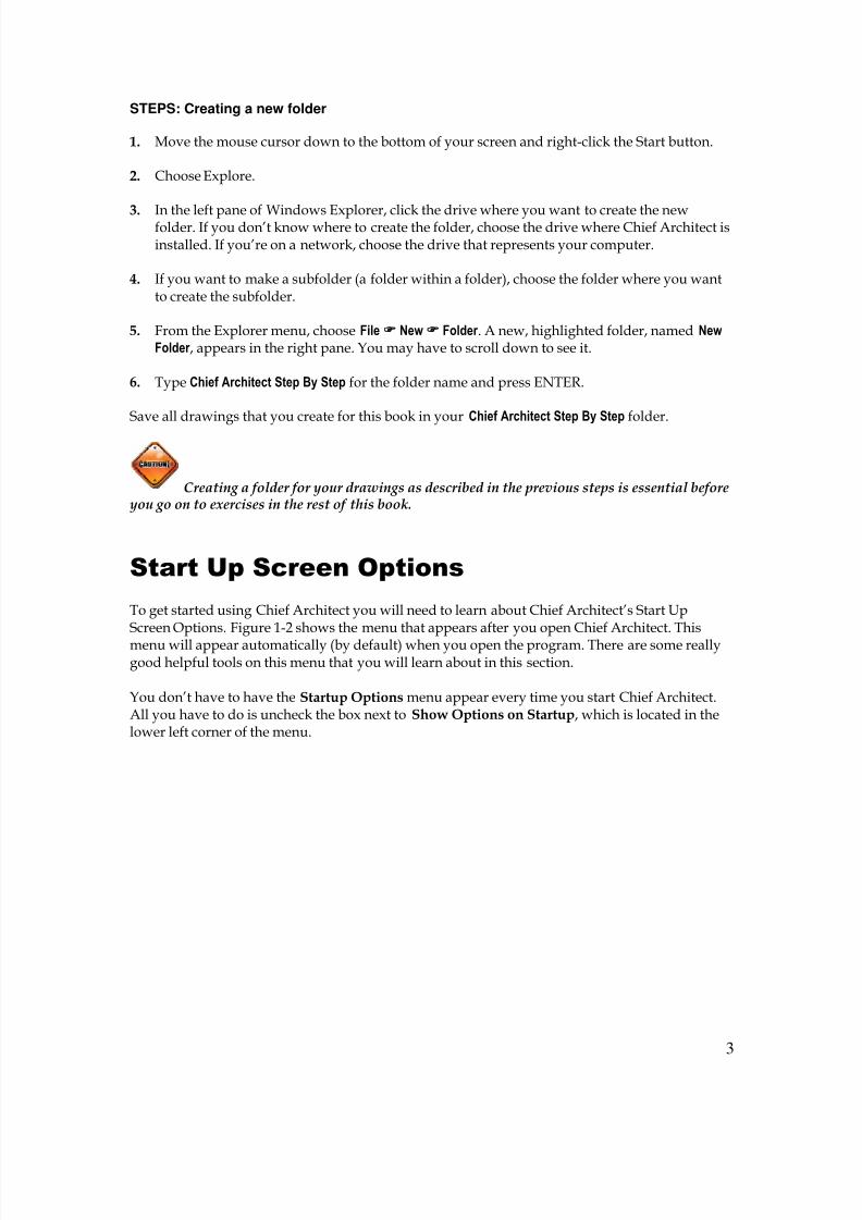
To get started using Chief Architect you will need to learn about Chief Architect’s Start UpScreen Options. Figure 1-2 shows the menu that appears after you open Chief Architect. This
menu will appear automatically (by default) when you open the program. There are some reallygood helpful tools on this menu that you will learn about in this section.
You don’t have to have the Startup Options menu appear every time you start Chief Architect.All you have to do is uncheck the box next to Show Options on Startup, which is located in thelower left corner of the menu.
8/4/2019 Chapter 1 Chief Architect
http://slidepdf.com/reader/full/chapter-1-chief-architect 4/54
4
Opening a New PlanIn the File section of the Startup Options menu clicking the New Plan button will open a newplan. This will be a new blank plan but what will actually happen is Chief Architect will open acopy of a template. A template is really a copy of a plan.
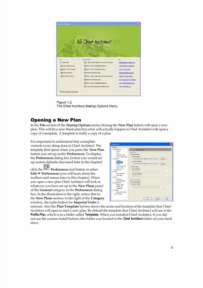
It is important to understand that a templatecontrols every thing done in Chief Architect. The
template that opens when you press the New Plan button was set up under Preferences. To displaythe Preferences dialog box (where you would setup system defaults discussed later in the chapter)
click the Preferences tool button or selectEdit Preferences (you will learn about thetoolbars and menus later in this chapter). Whenyou open a new plan Chief Architect will look atwhatever you have set up in the New Plans panelof the General category in the Preferences dialogbox. In the illustration to the right, notice that inthe New Plans section, to the right of the Category
window, the radio button for Imperial Units isselected. Also the Plan Template list box shows the name and location of the template that ChiefArchitect will open to start a new plan. By default the template that Chief Architect will use is theProfile.Plan, which is in a folder called Templates. When you installed Chief Architect, if you didnot use the custom install feature, this folder was located in the Chief Architect folder on your harddrive.
Figure 1-2 The Chief Architect Startup Options Menu
8/4/2019 Chapter 1 Chief Architect
http://slidepdf.com/reader/full/chapter-1-chief-architect 5/54
5
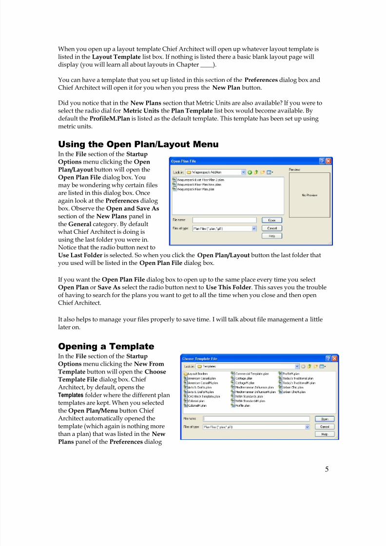
When you open up a layout template Chief Architect will open up whatever layout template islisted in the Layout Template list box. If nothing is listed there a basic blank layout page willdisplay (you will learn all about layouts in Chapter ____).
You can have a template that you set up listed in this section of the Preferences dialog box andChief Architect will open it for you when you press the New Plan button.
Did you notice that in the New Plans section that Metric Units are also available? If you were toselect the radio dial for Metric Units the Plan Template list box would become available. Bydefault the ProfileM.Plan is listed as the default template. This template has been set up usingmetric units.
Using the Open Plan/Layout MenuIn the File section of the StartupOptions menu clicking the OpenPlan/Layout button will open theOpen Plan File dialog box. Youmay be wondering why certain files
are listed in this dialog box. Onceagain look at the Preferences dialogbox. Observe the Open and Save As section of the New Plans panel inthe General category. By defaultwhat Chief Architect is doing isusing the last folder you were in.Notice that the radio button next toUse Last Folder is selected. So when you click the Open Plan/Layout button the last folder thatyou used will be listed in the Open Plan File dialog box.
If you want the Open Plan File dialog box to open up to the same place every time you select
Open Plan or Save As select the radio button next to Use This Folder. This saves you the troubleof having to search for the plans you want to get to all the time when you close and then openChief Architect.
It also helps to manage your files properly to save time. I will talk about file management a littlelater on.
Opening a TemplateIn the File section of the StartupOptions menu clicking the New FromTemplate button will open the Choose
Template File dialog box. ChiefArchitect, by default, opens theTemplates folder where the different plantemplates are kept. When you selectedthe Open Plan/Menu button ChiefArchitect automatically opened thetemplate (which again is nothing morethan a plan) that was listed in the NewPlans panel of the Preferences dialog
8/4/2019 Chapter 1 Chief Architect
http://slidepdf.com/reader/full/chapter-1-chief-architect 6/54
6
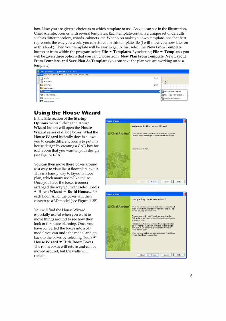
box. Now you are given a choice as to which template to use. As you can see in the illustration,Chief Architect comes with several templates. Each template contains a unique set of defaults,such as different colors, woods, cabinets, etc. When you make you own template, one that bestrepresents the way you work, you can store it in this template file (I will show you how later onin this book). Then your template will be easy to get to. Just select the New From Template button or from within the program select File Templates. By selecting File Templates you
will be given three options that you can choose from: New Plan From Template, New LayoutFrom Template, and Save Plan As Template (you can save the plan you are working on as atemplate).
Using the House Wizard In the File section of the StartupOptions menu clicking the House
Wizard button will open the House Wizard series of dialog boxes. What theHouse Wizard basically does is allowsyou to create different rooms to put in ahouse design by creating a CAD box foreach room that you want in your design(see Figure 1-3A).
You can then move these boxes around
as a way to visualize a floor plan layout.This is a handy way to layout a floorplan, which many users like to use.Once you have the boxes (rooms)arranged the way you want select Tools House Wizard Build House…foreach floor. All of the boxes will thenconvert to a 3D model (see Figure 1-3B).
You will find the House Wizardespecially useful when you want tomove things around to see how they
look or for space planning. Once youhave converted the boxes into a 3Dmodel you can undo the model and goback to the boxes by selecting Tools House Wizard Hide Room Boxes.The room boxes will return and can bemoved around, but the walls willremain.
8/4/2019 Chapter 1 Chief Architect
http://slidepdf.com/reader/full/chapter-1-chief-architect 7/54
7
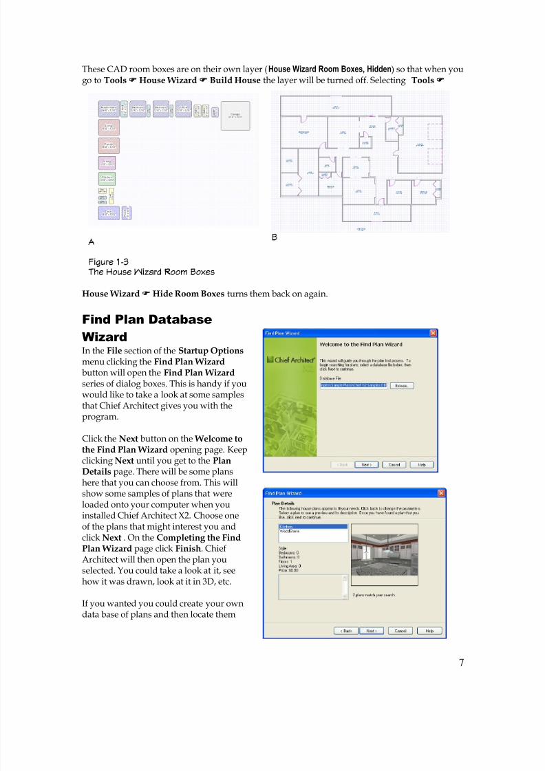
These CAD room boxes are on their own layer (House Wizard Room Boxes, Hidden) so that when yougo to Tools House Wizard Build House the layer will be turned off. Selecting Tools
House Wizard Hide Room Boxes turns them back on again.
Find Plan Database
WizardIn the File section of the Startup Options menu clicking the Find Plan Wizard button will open the Find Plan Wizardseries of dialog boxes. This is handy if youwould like to take a look at some samples
that Chief Architect gives you with theprogram.
Click the Next button on the Welcome tothe Find Plan Wizard opening page. Keepclicking Next until you get to the PlanDetails page. There will be some planshere that you can choose from. This willshow some samples of plans that wereloaded onto your computer when youinstalled Chief Architect X2. Choose oneof the plans that might interest you and
click Next . On the Completing the FindPlan Wizard page click Finish. ChiefArchitect will then open the plan youselected. You could take a look at it, seehow it was drawn, look at it in 3D, etc.
If you wanted you could create your owndata base of plans and then locate them
A
Figure 1-3
The House Wizard Room Boxes
B
8/4/2019 Chapter 1 Chief Architect
http://slidepdf.com/reader/full/chapter-1-chief-architect 8/54
8
using the Find Plan Wizard. I will show you how later in the book.
Setting Up Recent Files
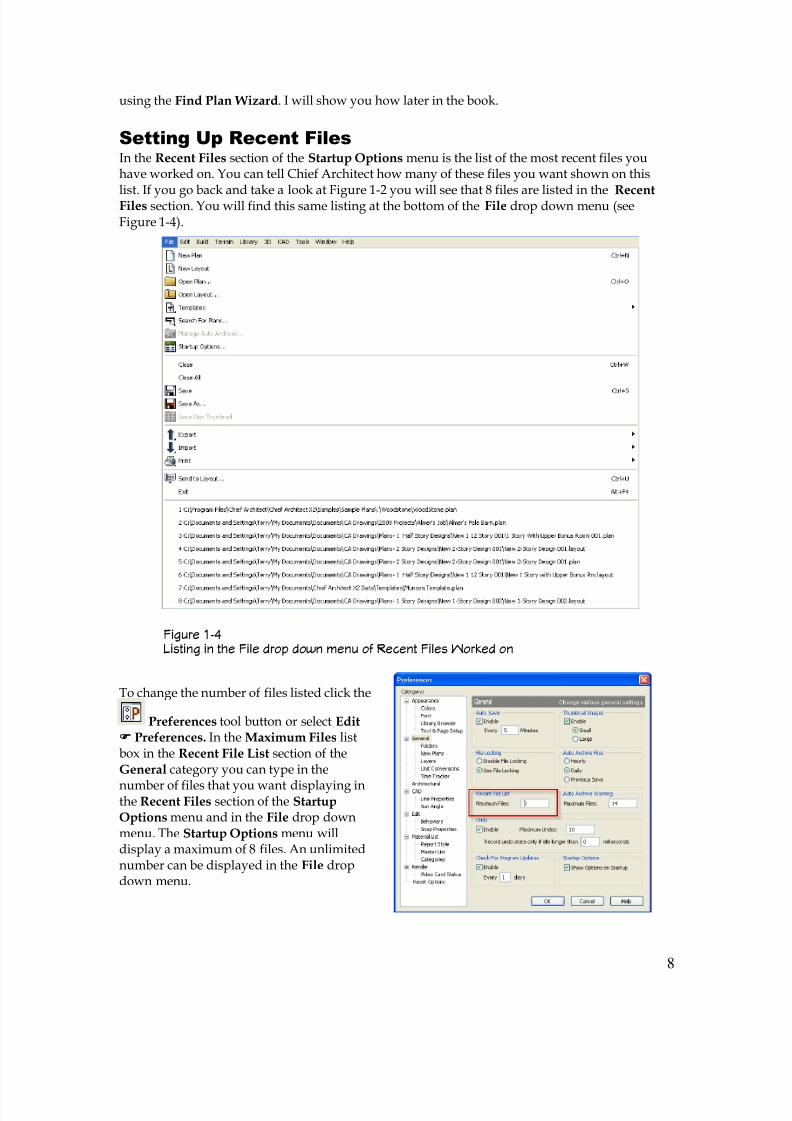
In the Recent Files section of the Startup Options menu is the list of the most recent files youhave worked on. You can tell Chief Architect how many of these files you want shown on this
list. If you go back and take a look at Figure 1-2 you will see that 8 files are listed in the RecentFiles section. You will find this same listing at the bottom of the File drop down menu (seeFigure 1-4).
To change the number of files listed click the
Preferences tool button or select Edit Preferences. In the Maximum Files listbox in the Recent File List section of theGeneral category you can type in the
number of files that you want displaying inthe Recent Files section of the StartupOptions menu and in the File drop downmenu. The Startup Options menu willdisplay a maximum of 8 files. An unlimitednumber can be displayed in the File dropdown menu.
Figure 1-4 Listing in the File drop down menu of Recent Files Worked on
8/4/2019 Chapter 1 Chief Architect
http://slidepdf.com/reader/full/chapter-1-chief-architect 9/54
9
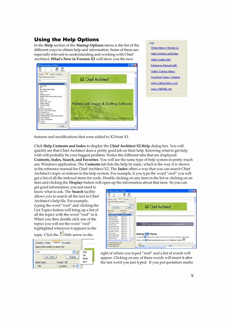
Using the Help Options
In the Help section of the Startup Options menu is the list of thedifferent ways to obtain help and information. Some of these are
especially relevant to understanding and working with ChiefArchitect. What’s New in Version X2 will show you the new
features and modifications that were added to X2 from X1.
Click Help Contents and Index to display the Chief Architect X2 Help dialog box. You willquickly see that Chief Architect does a pretty good job on their help. Knowing what to get helpwith will probably be your biggest problem. Notice the different tabs that are displayed:Contents, Index, Search, and Favorites. You will see the same type of help system in pretty muchany Windows application. The Contents tab lists the help by topic, which is the way it is shown
in the reference manual for Chief Architect X2. The Index offers a way that you can search ChiefArchitect’s topic or indexes in the help system. For example, if you type the word “roof” you willget a list of all the indexed items for roofs. Double clicking on any item in the list or clicking on anitem and clicking the Display button will open up the information about that item. So you canget good information, you just need toknow what to ask. The Search facilityallows you to search all the text in ChiefArchitect’s help file. For example,typing the word “roof” and clicking theList Topics button will bring up a list ofall the topics with the word “roof” in it.When you then double click one of the
topics you will see the word “roof”highlighted wherever it appears in the
topic. Click the little arrow to the
right of where you typed “roof” and a list of words willappear. Clicking on any of these words will insert it afterthe last word you just typed. If you put quotation marks
8/4/2019 Chapter 1 Chief Architect
http://slidepdf.com/reader/full/chapter-1-chief-architect 10/54
10
around a group of words that you typed, help will search for the phrase. To get rid of thehighlighting in the help document, right click the document and then click Refresh and thehighlighting will go away.
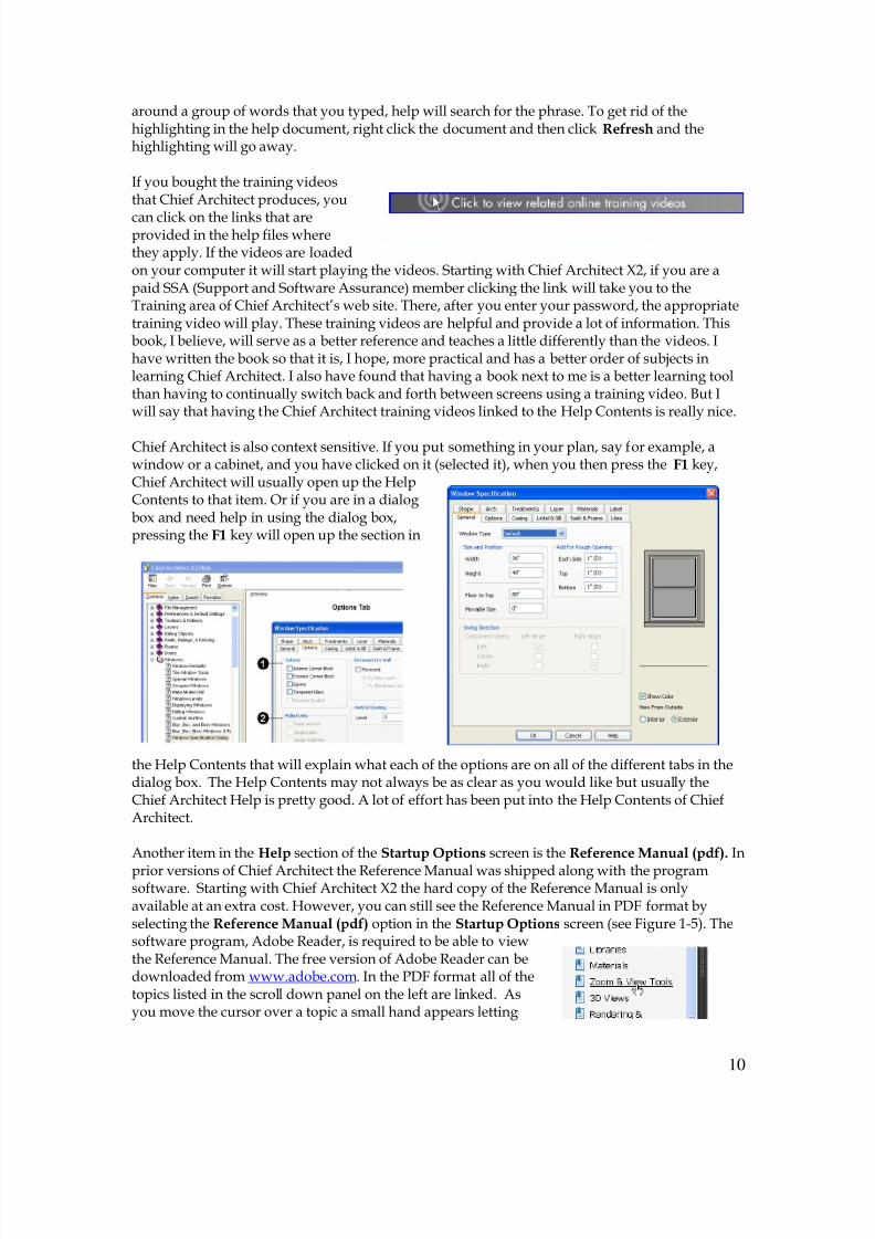
If you bought the training videosthat Chief Architect produces, you
can click on the links that areprovided in the help files wherethey apply. If the videos are loadedon your computer it will start playing the videos. Starting with Chief Architect X2, if you are apaid SSA (Support and Software Assurance) member clicking the link will take you to theTraining area of Chief Architect’s web site. There, after you enter your password, the appropriatetraining video will play. These training videos are helpful and provide a lot of information. Thisbook, I believe, will serve as a better reference and teaches a little differently than the videos. Ihave written the book so that it is, I hope, more practical and has a better order of subjects inlearning Chief Architect. I also have found that having a book next to me is a better learning toolthan having to continually switch back and forth between screens using a training video. But Iwill say that having the Chief Architect training videos linked to the Help Contents is really nice.
Chief Architect is also context sensitive. If you put something in your plan, say for example, awindow or a cabinet, and you have clicked on it (selected it), when you then press the F1 key,Chief Architect will usually open up the HelpContents to that item. Or if you are in a dialogbox and need help in using the dialog box,pressing the F1 key will open up the section in
the Help Contents that will explain what each of the options are on all of the different tabs in thedialog box. The Help Contents may not always be as clear as you would like but usually theChief Architect Help is pretty good. A lot of effort has been put into the Help Contents of ChiefArchitect.
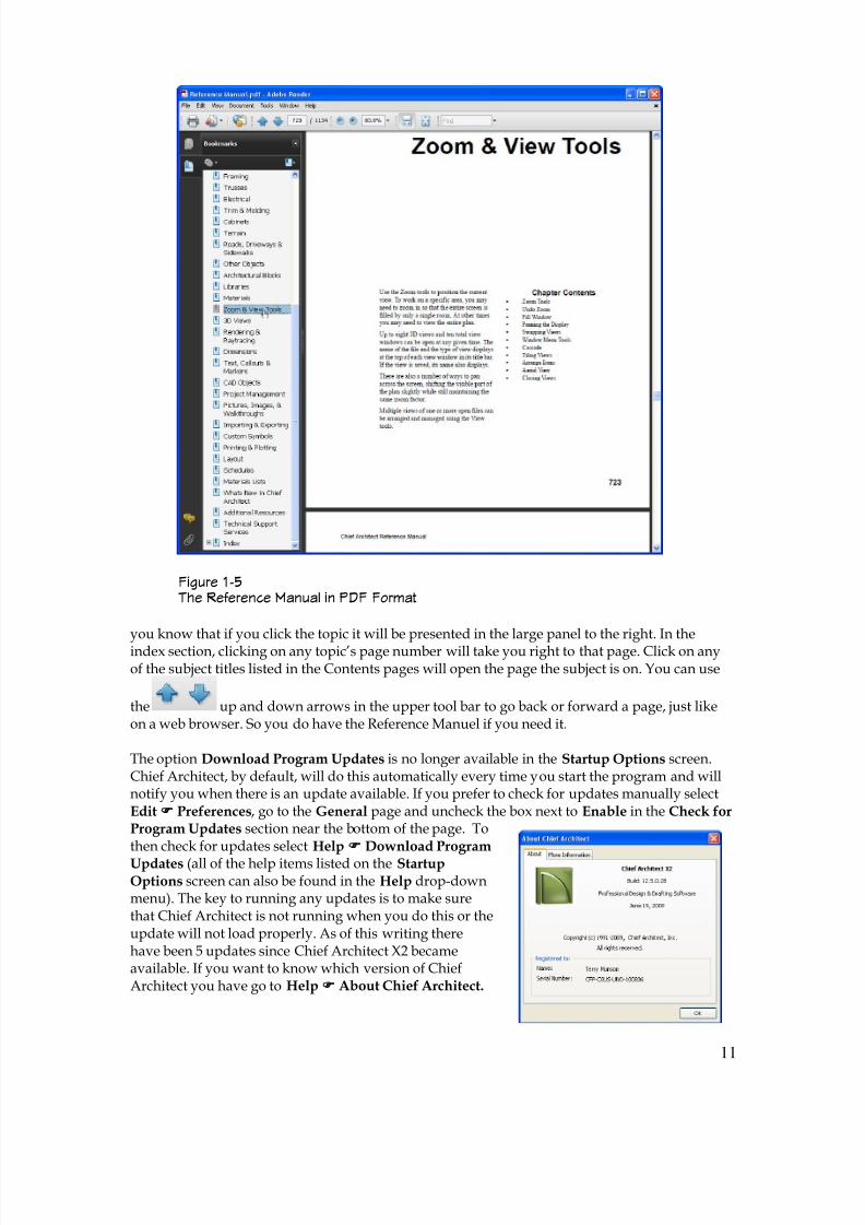
Another item in the Help section of the Startup Options screen is the Reference Manual (pdf). In
prior versions of Chief Architect the Reference Manual was shipped along with the programsoftware. Starting with Chief Architect X2 the hard copy of the Reference Manual is onlyavailable at an extra cost. However, you can still see the Reference Manual in PDF format byselecting the Reference Manual (pdf) option in the Startup Options screen (see Figure 1-5). Thesoftware program, Adobe Reader, is required to be able to viewthe Reference Manual. The free version of Adobe Reader can bedownloaded from www.adobe.com. In the PDF format all of thetopics listed in the scroll down panel on the left are linked. Asyou move the cursor over a topic a small hand appears letting
8/4/2019 Chapter 1 Chief Architect
http://slidepdf.com/reader/full/chapter-1-chief-architect 11/54
11
you know that if you click the topic it will be presented in the large panel to the right. In theindex section, clicking on any topic’s page number will take you right to that page. Click on anyof the subject titles listed in the Contents pages will open the page the subject is on. You can use
the up and down arrows in the upper tool bar to go back or forward a page, just likeon a web browser. So you do have the Reference Manuel if you need it.
The option Download Program Updates is no longer available in the Startup Options screen.Chief Architect, by default, will do this automatically every time you start the program and willnotify you when there is an update available. If you prefer to check for updates manually selectEdit Preferences, go to the General page and uncheck the box next to Enable in the Check forProgram Updates section near the bottom of the page. Tothen check for updates select Help Download Program
Updates (all of the help items listed on the StartupOptions screen can also be found in the Help drop-downmenu). The key to running any updates is to make surethat Chief Architect is not running when you do this or theupdate will not load properly. As of this writing therehave been 5 updates since Chief Architect X2 becameavailable. If you want to know which version of ChiefArchitect you have go to Help About Chief Architect.
Figure 1-5 The Reference Manual in PDF Format
8/4/2019 Chapter 1 Chief Architect
http://slidepdf.com/reader/full/chapter-1-chief-architect 12/54
12
The About Chief Architect dialog box will display showing you the current version of ChiefArchitect that you have installed on your computer. Whenever, a new software product becomesavailable and people begin using it and find issues, which, if then reported to the makers of ChiefArchitect, a “patch” can then be made to fix whatever the issue was. This is a pretty normalprocedure for most software products. You always want to make sure that you have the latestupdate and Chief Architect makes this easy for you to do by now making checking for updates
automatic.
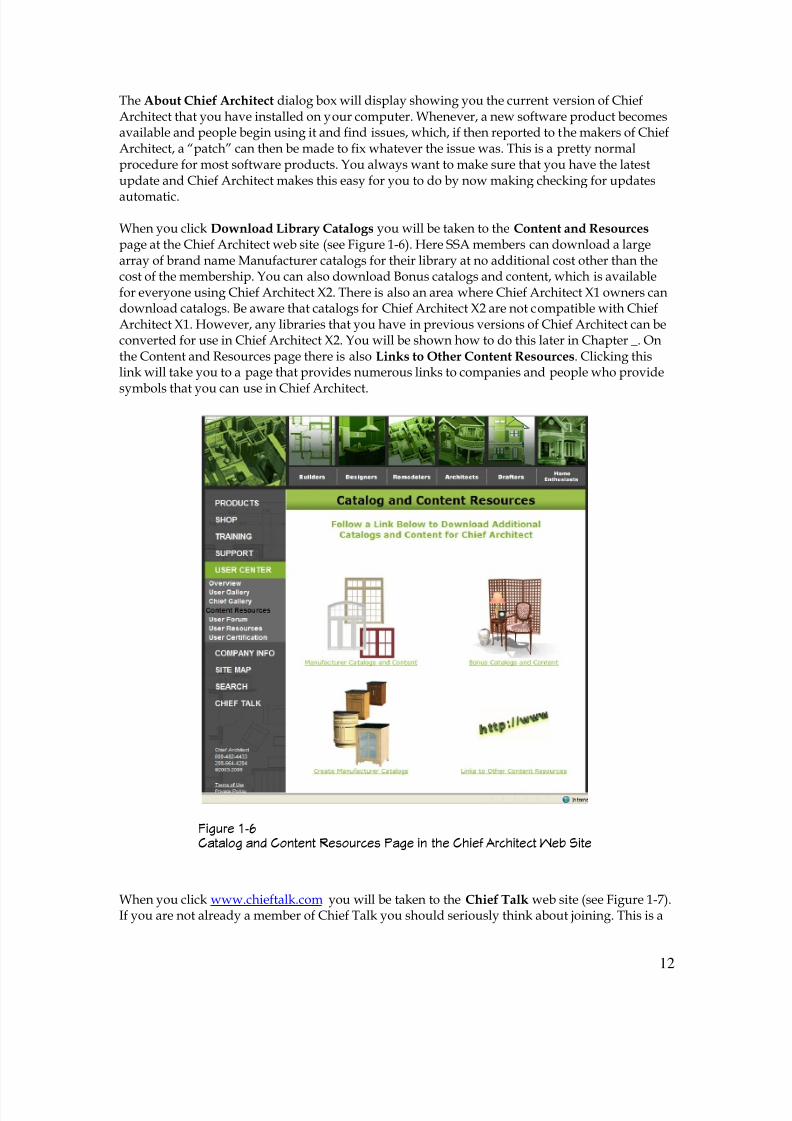
When you click Download Library Catalogs you will be taken to the Content and Resources page at the Chief Architect web site (see Figure 1-6). Here SSA members can download a largearray of brand name Manufacturer catalogs for their library at no additional cost other than thecost of the membership. You can also download Bonus catalogs and content, which is availablefor everyone using Chief Architect X2. There is also an area where Chief Architect X1 owners candownload catalogs. Be aware that catalogs for Chief Architect X2 are not compatible with ChiefArchitect X1. However, any libraries that you have in previous versions of Chief Architect can beconverted for use in Chief Architect X2. You will be shown how to do this later in Chapter _. Onthe Content and Resources page there is also Links to Other Content Resources. Clicking thislink will take you to a page that provides numerous links to companies and people who provide
symbols that you can use in Chief Architect.
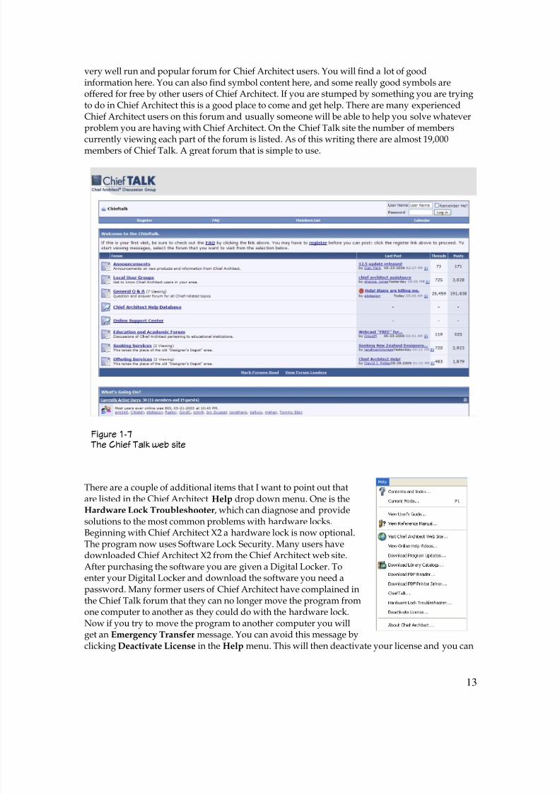
When you click www.chieftalk.com you will be taken to the Chief Talk web site (see Figure 1-7).If you are not already a member of Chief Talk you should seriously think about joining. This is a
Figure 1-6 Catalog and Content Resources Page in the Chief Architect Web Site
8/4/2019 Chapter 1 Chief Architect
http://slidepdf.com/reader/full/chapter-1-chief-architect 13/54
13
very well run and popular forum for Chief Architect users. You will find a lot of goodinformation here. You can also find symbol content here, and some really good symbols areoffered for free by other users of Chief Architect. If you are stumped by something you are tryingto do in Chief Architect this is a good place to come and get help. There are many experiencedChief Architect users on this forum and usually someone will be able to help you solve whateverproblem you are having with Chief Architect. On the Chief Talk site the number of members
currently viewing each part of the forum is listed. As of this writing there are almost 19,000members of Chief Talk. A great forum that is simple to use.
There are a couple of additional items that I want to point out thatare listed in the Chief Architect Help drop down menu. One is theHardware Lock Troubleshooter, which can diagnose and providesolutions to the most common problems with hardware locks.Beginning with Chief Architect X2 a hardware lock is now optional.The program now uses Software Lock Security. Many users have
downloaded Chief Architect X2 from the Chief Architect web site.After purchasing the software you are given a Digital Locker. Toenter your Digital Locker and download the software you need apassword. Many former users of Chief Architect have complained inthe Chief Talk forum that they can no longer move the program fromone computer to another as they could do with the hardware lock.Now if you try to move the program to another computer you willget an Emergency Transfer message. You can avoid this message byclicking Deactivate License in the Help menu. This will then deactivate your license and you can
Figure 1-7 The Chief Talk web site
8/4/2019 Chapter 1 Chief Architect
http://slidepdf.com/reader/full/chapter-1-chief-architect 14/54
14
then move the program to another computer and reactivate the license on that computer. Alicense of Chief Architect can only be active on one computer at any given time. You are limitedas to how many emergency transfers that you can do so it is important to avoid doing anemergency transfer unless it is actually an emergency such as a hard drive that quits to operate.
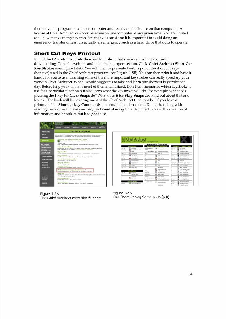
Short Cut Keys Printout In the Chief Architect web site there is a little sheet that you might want to considerdownloading. Go to the web site and go to their support section. Click Chief Architect Short-CutKey Strokes (see Figure 1-8A). You will then be presented with a pdf of the short cut keys(hotkeys) used in the Chief Architect program (see Figure. 1-8B). You can then print it and have ithandy for you to use. Learning some of the more important keystrokes can really speed up yourwork in Chief Architect. What I would suggest is to take and learn one shortcut keystroke perday. Before long you will have most of them memorized. Don’t just memorize which keystroke touse for a particular function but also learn what the keystroke will do. For example, what doespressing the 1 key for Clear Snaps do? What does S for Skip Snaps do? Find out about that andlearn it. The book will be covering most of the Chief Architect functions but if you have aprintout of the Shortcut Key Commands go through it and master it. Doing that along withreading the book will make you very proficient at using Chief Architect. You will learn a ton ofinformation and be able to put it to good use.
Figure 1-8A The Chief Architect Web Site Support
Figure 1-8B The Shortcut Key Commands (pdf)
8/4/2019 Chapter 1 Chief Architect
http://slidepdf.com/reader/full/chapter-1-chief-architect 15/54
15
Chief Architect X2 Toolbars and Menus
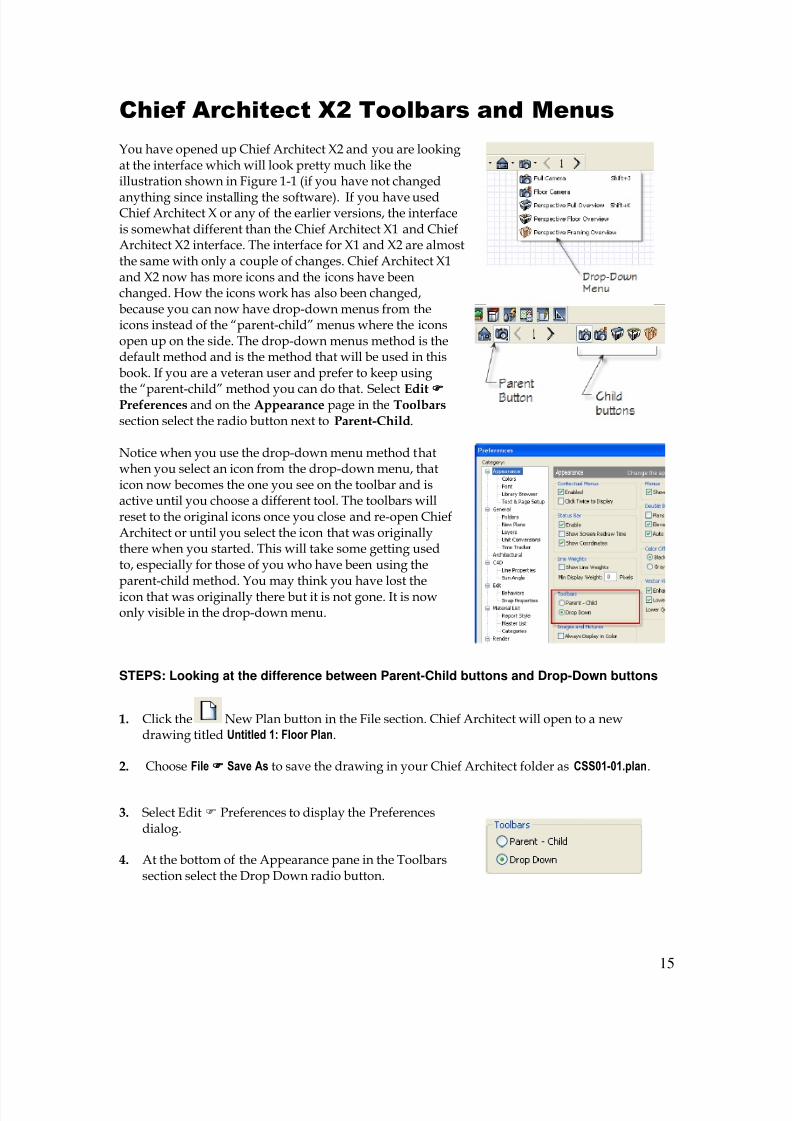
You have opened up Chief Architect X2 and you are lookingat the interface which will look pretty much like theillustration shown in Figure 1-1 (if you have not changed
anything since installing the software). If you have usedChief Architect X or any of the earlier versions, the interfaceis somewhat different than the Chief Architect X1 and ChiefArchitect X2 interface. The interface for X1 and X2 are almostthe same with only a couple of changes. Chief Architect X1and X2 now has more icons and the icons have beenchanged. How the icons work has also been changed,because you can now have drop-down menus from theicons instead of the “parent-child” menus where the iconsopen up on the side. The drop-down menus method is thedefault method and is the method that will be used in thisbook. If you are a veteran user and prefer to keep using
the “parent-child” method you can do that. Select Edit
Preferences and on the Appearance page in the Toolbars section select the radio button next to Parent-Child.
Notice when you use the drop-down menu method thatwhen you select an icon from the drop-down menu, thaticon now becomes the one you see on the toolbar and isactive until you choose a different tool. The toolbars willreset to the original icons once you close and re-open ChiefArchitect or until you select the icon that was originallythere when you started. This will take some getting usedto, especially for those of you who have been using theparent-child method. You may think you have lost theicon that was originally there but it is not gone. It is nowonly visible in the drop-down menu.
STEPS: Looking at the difference between Parent-Child buttons and Drop-Down buttons
1. Click the New Plan button in the File section. Chief Architect will open to a newdrawing titled Untitled 1: Floor Plan.
2. Choose File Save As to save the drawing in your Chief Architect folder as CSS01-01.plan.
3. Select Edit Preferences to display the Preferencesdialog.
4. At the bottom of the Appearance pane in the Toolbarssection select the Drop Down radio button.
8/4/2019 Chapter 1 Chief Architect
http://slidepdf.com/reader/full/chapter-1-chief-architect 16/54
16
5. Click OK.
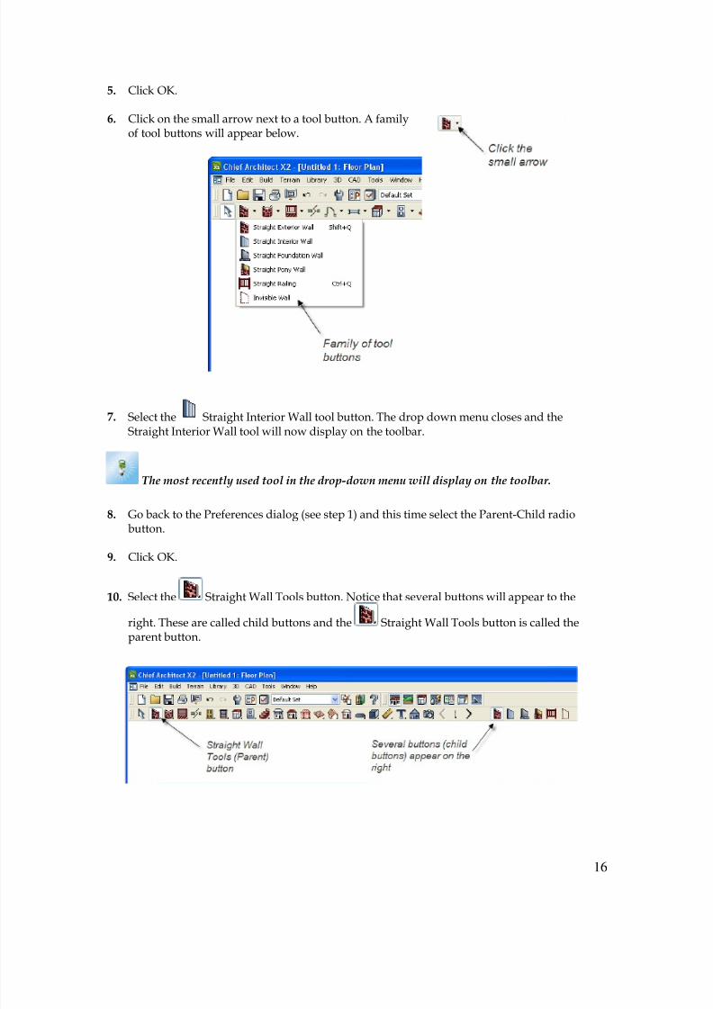
6. Click on the small arrow next to a tool button. A familyof tool buttons will appear below.
7. Select the Straight Interior Wall tool button. The drop down menu closes and theStraight Interior Wall tool will now display on the toolbar.
The most recently used tool in the drop-down menu will display on the toolbar.
8. Go back to the Preferences dialog (see step 1) and this time select the Parent-Child radio
button.
9. Click OK.
10. Select the Straight Wall Tools button. Notice that several buttons will appear to the
right. These are called child buttons and the Straight Wall Tools button is called theparent button.
8/4/2019 Chapter 1 Chief Architect
http://slidepdf.com/reader/full/chapter-1-chief-architect 17/54
17
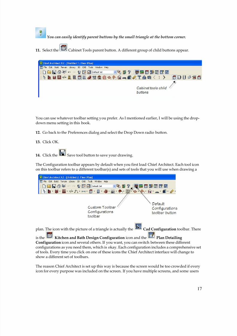
You can easily identify parent buttons by the small triangle at the bottom corner.
11. Select the Cabinet Tools parent button. A different group of child buttons appear.
You can use whatever toolbar setting you prefer. As I mentioned earlier, I will be using the drop-down menu setting in this book.
12. Go back to the Preferences dialog and select the Drop Down radio button.
13. Click OK.
14. Click the Save tool button to save your drawing.
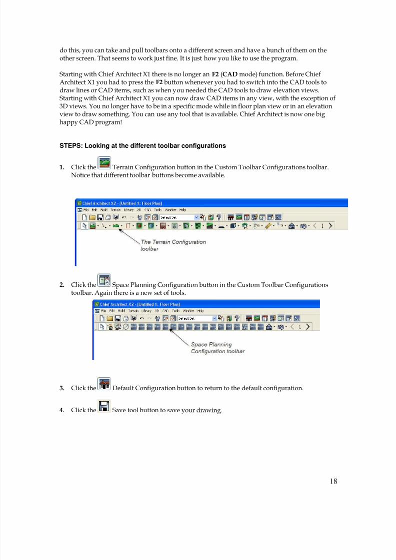
The Configuration toolbar appears by default when you first load Chief Architect. Each tool iconon this toolbar refers to a different toolbar(s) and sets of tools that you will use when drawing a
plan. The icon with the picture of a triangle is actually the Cad Configuration toolbar. There
is the Kitchen and Bath Design Configuration icon and the Plan Detailing Configuration icon and several others. If you want, you can switch between these differentconfigurations as you need them, which is okay. Each configuration includes a comprehensive setof tools. Every time you click on one of these icons the Chief Architect interface will change toshow a different set of toolbars.
The reason Chief Architect is set up this way is because the screen would be too crowded if everyicon for every purpose was included on the screen. If you have multiple screens, and some users
8/4/2019 Chapter 1 Chief Architect
http://slidepdf.com/reader/full/chapter-1-chief-architect 18/54
18
do this, you can take and pull toolbars onto a different screen and have a bunch of them on theother screen. That seems to work just fine. It is just how you like to use the program.
Starting with Chief Architect X1 there is no longer an F2 (CAD mode) function. Before ChiefArchitect X1 you had to press the F2 button whenever you had to switch into the CAD tools todraw lines or CAD items, such as when you needed the CAD tools to draw elevation views.
Starting with Chief Architect X1 you can now draw CAD items in any view, with the exception of3D views. You no longer have to be in a specific mode while in floor plan view or in an elevationview to draw something. You can use any tool that is available. Chief Architect is now one bighappy CAD program!
STEPS: Looking at the different toolbar configurations
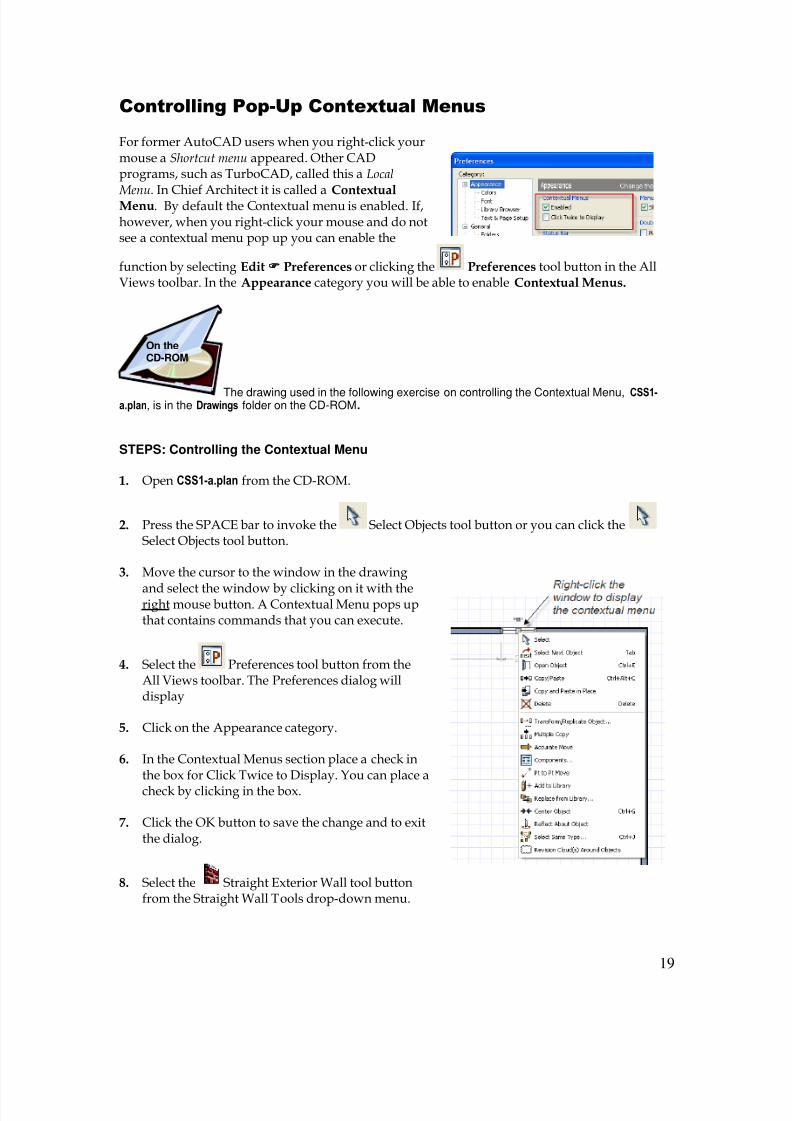
1. Click the Terrain Configuration button in the Custom Toolbar Configurations toolbar.Notice that different toolbar buttons become available.
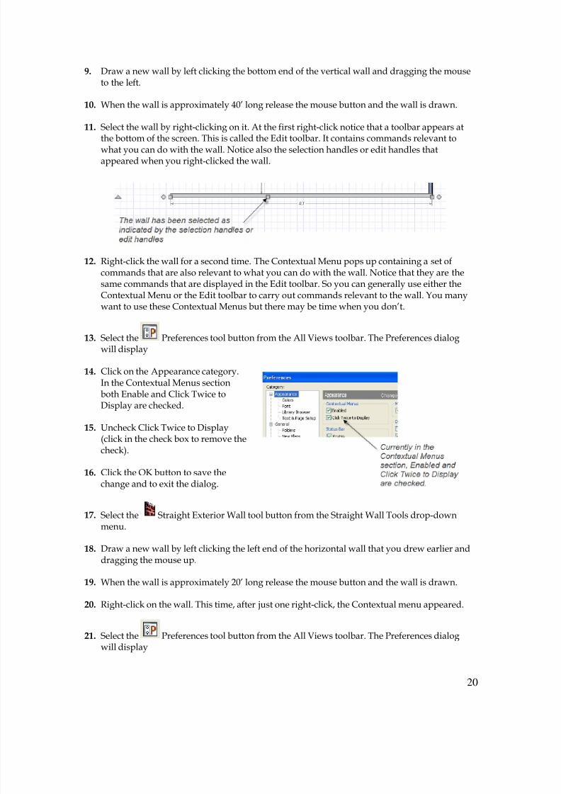
2. Click the Space Planning Configuration button in the Custom Toolbar Configurations
toolbar. Again there is a new set of tools.
3. Click the Default Configuration button to return to the default configuration.
4. Click the Save tool button to save your drawing.
8/4/2019 Chapter 1 Chief Architect
http://slidepdf.com/reader/full/chapter-1-chief-architect 19/54
19
Controlling Pop-Up Contextual Menus
For former AutoCAD users when you right-click yourmouse a Shortcut menu appeared. Other CADprograms, such as TurboCAD, called this a Local
Menu. In Chief Architect it is called a ContextualMenu. By default the Contextual menu is enabled. If,however, when you right-click your mouse and do notsee a contextual menu pop up you can enable the
function by selecting Edit Preferences or clicking the Preferences tool button in the AllViews toolbar. In the Appearance category you will be able to enable Contextual Menus.
The drawing used in the following exercise on controlling the Contextual Menu, CSS1-a.plan, is in the Drawings folder on the CD-ROM.
STEPS: Controlling the Contextual Menu
1. Open CSS1-a.plan from the CD-ROM.
2. Press the SPACE bar to invoke the Select Objects tool button or you can click theSelect Objects tool button.
3. Move the cursor to the window in the drawing
and select the window by clicking on it with theright mouse button. A Contextual Menu pops upthat contains commands that you can execute.
4. Select the Preferences tool button from theAll Views toolbar. The Preferences dialog willdisplay
5. Click on the Appearance category.
6. In the Contextual Menus section place a check inthe box for Click Twice to Display. You can place acheck by clicking in the box.
7. Click the OK button to save the change and to exitthe dialog.
8. Select the Straight Exterior Wall tool buttonfrom the Straight Wall Tools drop-down menu.
On theCD-ROM
8/4/2019 Chapter 1 Chief Architect
http://slidepdf.com/reader/full/chapter-1-chief-architect 20/54
20
9. Draw a new wall by left clicking the bottom end of the vertical wall and dragging the mouseto the left.
10. When the wall is approximately 40’ long release the mouse button and the wall is drawn.
11. Select the wall by right-clicking on it. At the first right-click notice that a toolbar appears at
the bottom of the screen. This is called the Edit toolbar. It contains commands relevant towhat you can do with the wall. Notice also the selection handles or edit handles thatappeared when you right-clicked the wall.
12. Right-click the wall for a second time. The Contextual Menu pops up containing a set ofcommands that are also relevant to what you can do with the wall. Notice that they are thesame commands that are displayed in the Edit toolbar. So you can generally use either theContextual Menu or the Edit toolbar to carry out commands relevant to the wall. You manywant to use these Contextual Menus but there may be time when you don’t.
13. Select the Preferences tool button from the All Views toolbar. The Preferences dialogwill display
14. Click on the Appearance category.In the Contextual Menus sectionboth Enable and Click Twice toDisplay are checked.
15. Uncheck Click Twice to Display(click in the check box to remove thecheck).
16. Click the OK button to save thechange and to exit the dialog.
17. Select the Straight Exterior Wall tool button from the Straight Wall Tools drop-downmenu.
18. Draw a new wall by left clicking the left end of the horizontal wall that you drew earlier and
dragging the mouse up.
19. When the wall is approximately 20’ long release the mouse button and the wall is drawn.
20. Right-click on the wall. This time, after just one right-click, the Contextual menu appeared.
21. Select the Preferences tool button from the All Views toolbar. The Preferences dialogwill display
8/4/2019 Chapter 1 Chief Architect
http://slidepdf.com/reader/full/chapter-1-chief-architect 21/54
21
22. Click on the Appearance category.
23. In the Contextual Menus section, uncheck Enabled.
24. Click the OK button to save the change and to exit the dialog.
25. Right click the vertical wall you just drew. Now the Contextual Menu does not appear. Thecommands, however, are still available in the Edit toolbar, which displays when you eitherright-click or left-click to select the wall or any object.
26. Go back to the Preferences dialog and in the Contextual Menus section re-check Enabled.
27. Close the drawing. Select No when asked if you want to save the modifications.
So whenever you want to modify the display of Contextual Menus go to Edit Preferences or
select the Preferences tool button from the All Views toolbar. Then go to the Appearance category and the options you choose will remain selected every time you use Chief Architectuntil you change them again.
Extended Tool Configuration
The following exercise will display the Extended Tool Configuration setup on your display of theChief Architect X2 interface. I believe that this configuration set-up will save you time whenworking with Chief Architect X2. I will be using this configuration for the rest of the book.
STEPS: Looking at the Extended Tool Configuration
1. Open your CSS01-01.plan if it is not already open. If you did not create this drawing you canuse CSS1-b.plan that is on the CD.
2. Move the cursor over any tool button in any of the
toolbars and right-click.
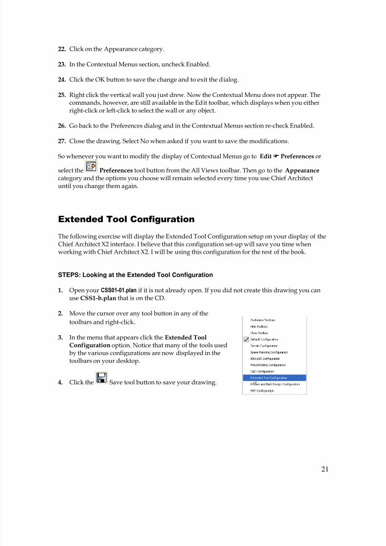
3. In the menu that appears click the Extended ToolConfiguration option. Notice that many of the tools usedby the various configurations are now displayed in thetoolbars on your desktop.
4. Click the Save tool button to save your drawing.
8/4/2019 Chapter 1 Chief Architect
http://slidepdf.com/reader/full/chapter-1-chief-architect 22/54
22
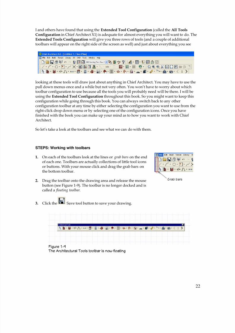
Figure 1-9 The Architectural Tools toolbar is now floating
I and others have found that using the Extended Tool Configuration (called the All ToolsConfiguration in Chief Architect X1) is adequate for almost everything you will want to do. TheExtended Tools Configuration will give you three rows of tools (and a couple of additionaltoolbars will appear on the right side of the screen as well) and just about everything you see
looking at these tools will draw just about anything in Chief Architect. You may have to use thepull down menus once and a while but not very often. You won’t have to worry about whichtoolbar configuration to use because all the tools you will probably need will be there. I will beusing the Extended Tool Configuration throughout this book. So you might want to keep thisconfiguration while going through this book. You can always switch back to any otherconfiguration toolbar at any time by either selecting the configuration you want to use from theright-click drop down menu or by selecting one of the configuration icons. Once you have
finished with the book you can make up your mind as to how you want to work with ChiefArchitect.
So let’s take a look at the toolbars and see what we can do with them.
STEPS: Working with toolbars
1. On each of the toolbars look at the lines or grab bars on the endof each one. Toolbars are actually collections of little tool iconsor buttons. With your mouse click and drag the grab bars onthe bottom toolbar.
2. Drag the toolbar onto the drawing area and release the mousebutton (see Figure 1-9). The toolbar is no longer docked and iscalled a floating toolbar .
3. Click the Save tool button to save your drawing.
8/4/2019 Chapter 1 Chief Architect
http://slidepdf.com/reader/full/chapter-1-chief-architect 23/54
23
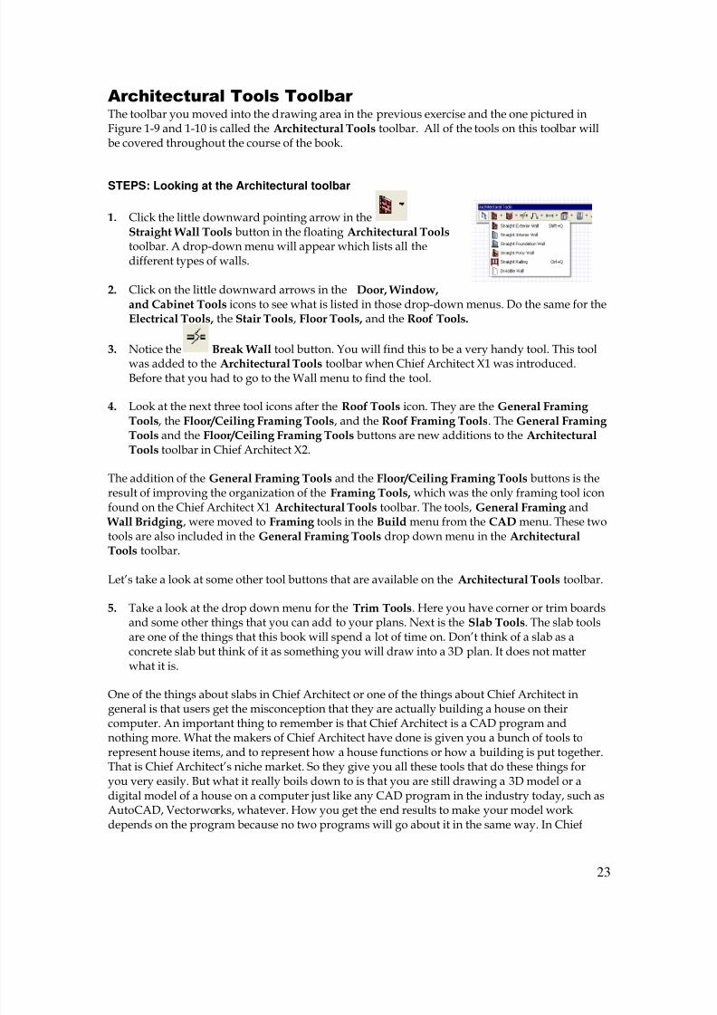
Architectural Tools Toolbar The toolbar you moved into the drawing area in the previous exercise and the one pictured inFigure 1-9 and 1-10 is called the Architectural Tools toolbar. All of the tools on this toolbar willbe covered throughout the course of the book.
STEPS: Looking at the Architectural toolbar
1. Click the little downward pointing arrow in theStraight Wall Tools button in the floating Architectural Tools toolbar. A drop-down menu will appear which lists all thedifferent types of walls.
2. Click on the little downward arrows in the Door, Window,and Cabinet Tools icons to see what is listed in those drop-down menus. Do the same for theElectrical Tools, the Stair Tools, Floor Tools, and the Roof Tools.
3.
Notice the Break Wall tool button. You will find this to be a very handy tool. This toolwas added to the Architectural Tools toolbar when Chief Architect X1 was introduced.Before that you had to go to the Wall menu to find the tool.
4. Look at the next three tool icons after the Roof Tools icon. They are the General Framing Tools, the Floor/Ceiling Framing Tools, and the Roof Framing Tools. The General Framing Tools and the Floor/Ceiling Framing Tools buttons are new additions to the ArchitecturalTools toolbar in Chief Architect X2.
The addition of the General Framing Tools and the Floor/Ceiling Framing Tools buttons is theresult of improving the organization of the Framing Tools, which was the only framing tool iconfound on the Chief Architect X1 Architectural Tools toolbar. The tools, General Framing and
Wall Bridging , were moved to Framing tools in the Build menu from the CAD menu. These two
tools are also included in the General Framing Tools drop down menu in the ArchitecturalTools toolbar.
Let’s take a look at some other tool buttons that are available on the Architectural Tools toolbar.
5. Take a look at the drop down menu for the Trim Tools. Here you have corner or trim boardsand some other things that you can add to your plans. Next is the Slab Tools. The slab toolsare one of the things that this book will spend a lot of time on. Don’t think of a slab as aconcrete slab but think of it as something you will draw into a 3D plan. It does not matterwhat it is.
One of the things about slabs in Chief Architect or one of the things about Chief Architect in
general is that users get the misconception that they are actually building a house on theircomputer. An important thing to remember is that Chief Architect is a CAD program andnothing more. What the makers of Chief Architect have done is given you a bunch of tools torepresent house items, and to represent how a house functions or how a building is put together.That is Chief Architect’s niche market. So they give you all these tools that do these things foryou very easily. But what it really boils down to is that you are still drawing a 3D model or adigital model of a house on a computer just like any CAD program in the industry today, such asAutoCAD, Vectorworks, whatever. How you get the end results to make your model workdepends on the program because no two programs will go about it in the same way. In Chief

8/4/2019 Chapter 1 Chief Architect
http://slidepdf.com/reader/full/chapter-1-chief-architect 24/54
24
Architect’s case you have tools for walls, cabinets, etc. So Chief Architect has made some toolsthat really make drawing a building relatively easy. Sure, you will run into some difficulties andhave to deal with some quirks in the program but all and all it works very well. The slab tool willlet you draw lots of elements in your plan that can represent molding, trim, for back splashes, fortiles, for whatever. You can even use it to fix walls. You can use the slab tools to do a lot ofdifferent things.
Let’s continue on with looking at the Architectural Tools toolbar.
6. In Chief Architect X1 the Primitive Tools were added to the program. Click the arrow forthe drop down menu and you will see tools that you can use to make boxes, spheres,cylinders, cones and any polyline solid. There are specific ways to use the primitive tools andthis book will cover some of those ways.
7. Next are the Dimension Tools and the Text Tools. Take a look at those. You will be usingthese tools to add dimensions and text to your plans.
8. Take a look at the two camera tools. They have been renamed in Chief Architect X2. In Chief
Architect X2 all overviews can now be either perspective or orthographic. The VectorCamera View tools are now called the Perspective View Tools and the Render Camera ViewTools are now called the Orthographic View Tools.
9. Click the Save tool button to save your drawing.
The Perspective View Tools do everything mathematically and the Orthographic Tools doeverything with photos or textures. Anytime you hear the word texture in Chief Architect or inany CAD program or in any program actually, what they are really saying is photos. A texture isa picture of something. That is all it is. The way textures work in CAD and in all programs is, sayyou might have a small picture of some roof shingles or bricks, the program will take that pictureand tile it over the surface of an object in the drawing. It will keep tiling it over and over until the
entire surface is covered. If you have a good picture it will look seamless. That is how a textureworks.
So you have just seen some of the tools that are available in the Architectural Tools toolbar. The
last item at the very right end of the toolbar is an iconthat will allow you to go from one floor in your plan to the nextfloor and back again. Clicking on the floor number will displaythe Change Floor Reference dialog box. You can use this dialogbox to change the floor you are viewing and which floor will showup in reference. Reference gives you the ability to; for example, seethe walls on the first floor in the plan while you are on the second
floor in the plan. The reference function, beginning with ChiefArchitect X1 is handled differently than in all of the previousversions of Chief. You will see how the reference function works inChapter _.
8/4/2019 Chapter 1 Chief Architect
http://slidepdf.com/reader/full/chapter-1-chief-architect 25/54
25
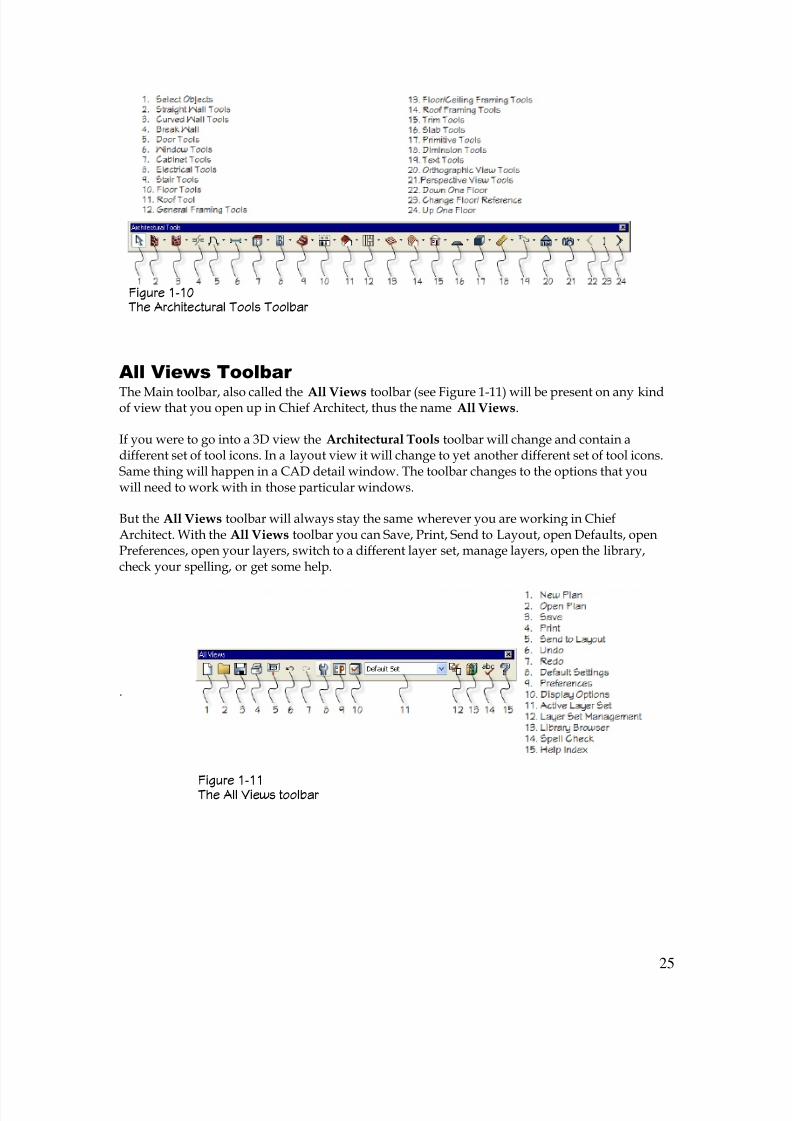
All Views Toolbar
The Main toolbar, also called the All Views toolbar (see Figure 1-11) will be present on any kindof view that you open up in Chief Architect, thus the name All Views.
If you were to go into a 3D view the Architectural Tools toolbar will change and contain adifferent set of tool icons. In a layout view it will change to yet another different set of tool icons.Same thing will happen in a CAD detail window. The toolbar changes to the options that youwill need to work with in those particular windows.
But the All Views toolbar will always stay the same wherever you are working in ChiefArchitect. With the All Views toolbar you can Save, Print, Send to Layout, open Defaults, openPreferences, open your layers, switch to a different layer set, manage layers, open the library,check your spelling, or get some help.
.
Figure 1-11 The All Views toolbar
Figure 1-10 The Architectural Tools Toolbar
8/4/2019 Chapter 1 Chief Architect
http://slidepdf.com/reader/full/chapter-1-chief-architect 26/54
26
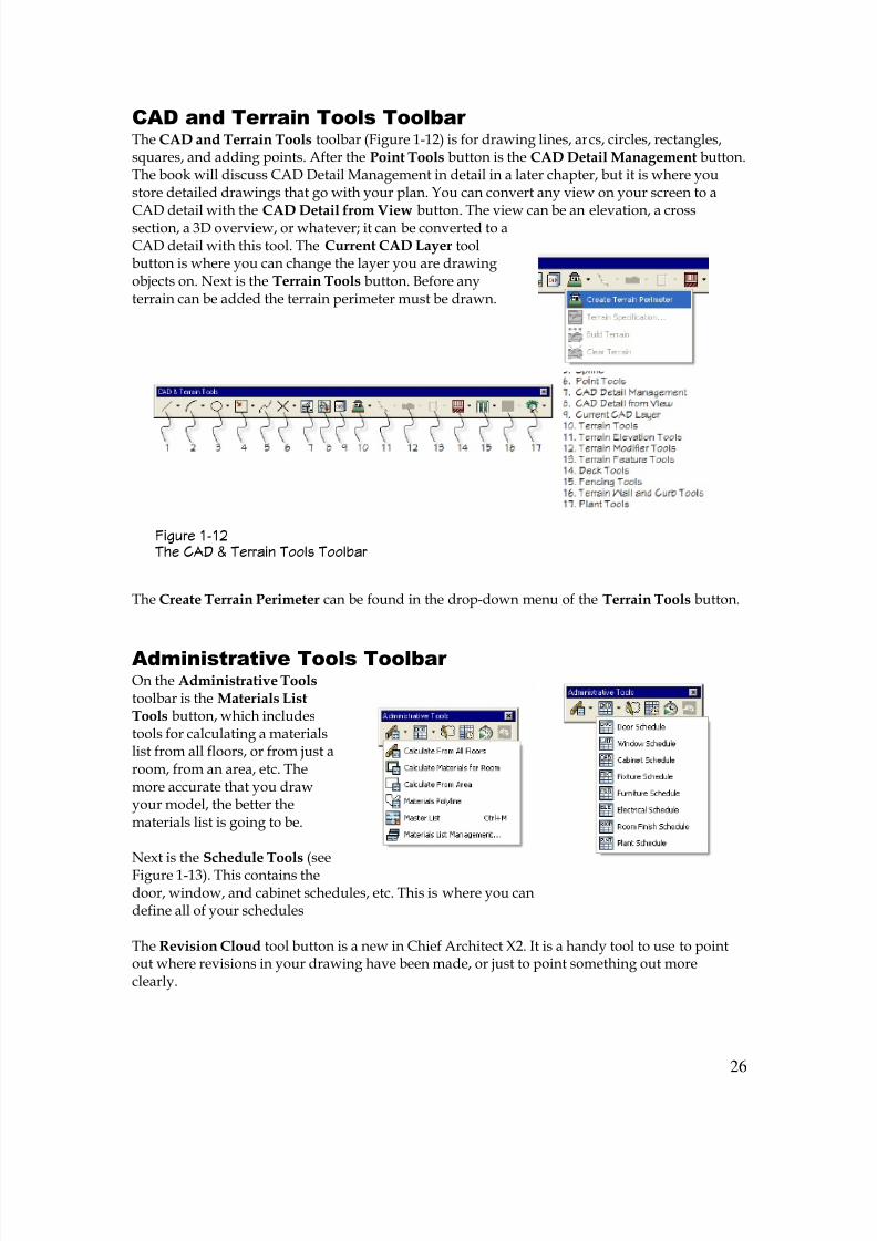
CAD and Terrain Tools Toolbar The CAD and Terrain Tools toolbar (Figure 1-12) is for drawing lines, arcs, circles, rectangles,squares, and adding points. After the Point Tools button is the CAD Detail Management button.The book will discuss CAD Detail Management in detail in a later chapter, but it is where youstore detailed drawings that go with your plan. You can convert any view on your screen to a
CAD detail with the CAD Detail from View button. The view can be an elevation, a crosssection, a 3D overview, or whatever; it can be converted to aCAD detail with this tool. The Current CAD Layer toolbutton is where you can change the layer you are drawingobjects on. Next is the Terrain Tools button. Before anyterrain can be added the terrain perimeter must be drawn.
The Create Terrain Perimeter can be found in the drop-down menu of the Terrain Tools button.
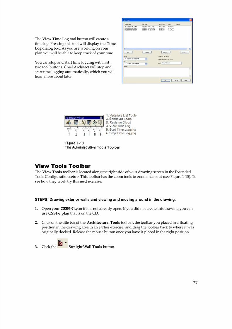
Administrative Tools Toolbar On the Administrative Tools toolbar is the Materials ListTools button, which includestools for calculating a materialslist from all floors, or from just aroom, from an area, etc. Themore accurate that you drawyour model, the better thematerials list is going to be.
Next is the Schedule Tools (see
Figure 1-13). This contains thedoor, window, and cabinet schedules, etc. This is where you candefine all of your schedules
The Revision Cloud tool button is a new in Chief Architect X2. It is a handy tool to use to pointout where revisions in your drawing have been made, or just to point something out moreclearly.
Figure 1-12 The CAD & Terrain Tools Toolbar
8/4/2019 Chapter 1 Chief Architect
http://slidepdf.com/reader/full/chapter-1-chief-architect 27/54

8/4/2019 Chapter 1 Chief Architect
http://slidepdf.com/reader/full/chapter-1-chief-architect 28/54
28
4. Move the cursor into the drawing area. Notice that the cursor changes into a small cross.Click near the left side of the drawing area and then drag the cursor to the right. A wall witha temporary dimension follows the cursor as you drag. When the temporary dimension
shows 30’-0” click the mouse button. A wall 30’ long is displayed.
5. Start another wall by clicking on the end of the first
wall and drag downward. Click again when thetemporary dimension shows 20’-0”. Continue in acounterclockwise direction to form a building that is30’ x 20’ as shown to the right. When you drawexterior walls in Chief Architect try to draw them in acounterclockwise direction. That way the exteriormaterial (siding, brick, etc.) will display on the exteriorside of the wall.
6. Click the Zoom tool (the hotkey for this tool isSHIFT + Z) in the View Tools toolbar. Move thecursor into the drawing area. The cursor resembles a
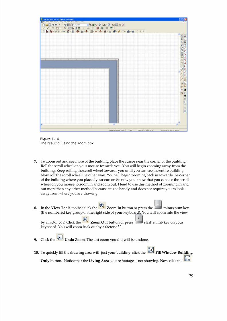
magnifying glass. Click a point to the left and abovethe top right corner of the building and then dragthe cursor to the right and below the buildingcorner. A shaded rectangle forms giving you avisual on which area you are zooming in on. Releasethe mouse button. The screen will fill with the areathat you drew a rectangle or zoom box around (seeFigure 1-14).
8/4/2019 Chapter 1 Chief Architect
http://slidepdf.com/reader/full/chapter-1-chief-architect 29/54
29
7. To zoom out and see more of the building place the cursor near the corner of the building.Roll the scroll wheel on your mouse towards you. You will begin zooming away from thebuilding. Keep rolling the scroll wheel towards you until you can see the entire building.Now roll the scroll wheel the other way. You will begin zooming back in towards the cornerof the building where you placed your cursor. So now you know that you can use the scrollwheel on you mouse to zoom in and zoom out. I tend to use this method of zooming in andout more than any other method because it is so handy and does not require you to lookaway from where you are drawing.
8. In the View Tools toolbar click the Zoom In button or press the minus num key(the numbered key group on the right side of your keyboard). You will zoom into the view
by a factor of 2. Click the Zoom Out button or press slash numb key on yourkeyboard. You will zoom back out by a factor of 2.
9. Click the Undo Zoom. The last zoom you did will be undone.
10. To quickly fill the drawing area with just your building, click the Fill Window Building
Only button. Notice that the Living Area square footage is not showing. Now click the
Figure 1-14 The result of using the zoom box

8/4/2019 Chapter 1 Chief Architect
http://slidepdf.com/reader/full/chapter-1-chief-architect 30/54
30
Fill Window (the hotkey is F6) button. The drawing window will be filled but it will nowinclude everything in your drawing. You can now see the Living Area square footage.
11. Click the Pan Window tool icon. Move the cursor into the drawing area. The cursor
looks like a hand. Click the left mouse button and you will be able to move the screenaround. This is called panning the drawing. Click the mouse button again. You can no longer
pan. You must click the Pan Window tool icon again to pan. Here again is where thescroll wheel on your mouse becomes a very handy tool. Press the scroll wheel. The cursorlooks like a hand and you can pan the drawing as long as you press the scroll wheel.
12. Click the Save tool button to save your drawing.
If the scroll wheel on your mouse also tilts to the left or right you can use that function to movethe screen in Chief Architect back and forth.
Being able to use the scroll wheel to pan was a new feature that came out with Chief Architect X1.This tool can be used in any view you are in.
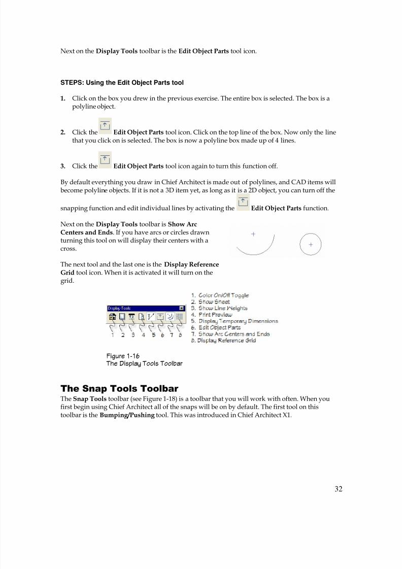
Display Tools Toolbar Let’s take a look at the Display Tools toolbar (see Figure 1-16). The Color On/Off toggle icon(the hotkey is F8) turns the color on and off in all the different views. This includes photos youhave in your plan.
The next tool is the Show Sheet tool. If you have your printer set up and you have your sheetsize set to a certain size clicking this tool will show the sheet on your screen. Generally you don’tneed to worry about this tool unless you are on a layout page. You would rarely need to use this
tool while in floor plan.
STEPS: Looking at the Show Line Weights tool
1. Open your CSS01-01.plan if it is not already open. If you did not create this drawing you canuse CSS1-d.plan that is on the CD.
Figure 1-15 The View Tools Toolbar
8/4/2019 Chapter 1 Chief Architect
http://slidepdf.com/reader/full/chapter-1-chief-architect 31/54
31
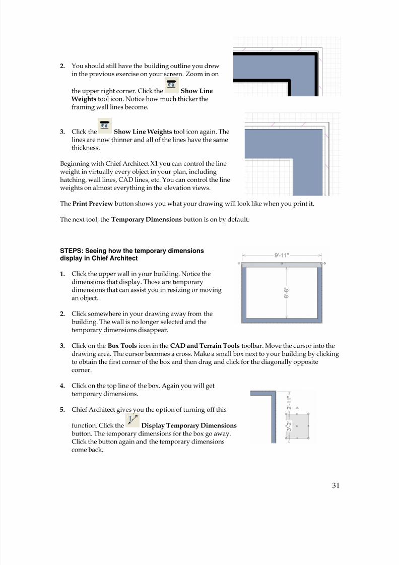
2. You should still have the building outline you drewin the previous exercise on your screen. Zoom in on
the upper right corner. Click the Show Line
Weights tool icon. Notice how much thicker theframing wall lines become.
3. Click the Show Line Weights tool icon again. Thelines are now thinner and all of the lines have the samethickness.
Beginning with Chief Architect X1 you can control the lineweight in virtually every object in your plan, includinghatching, wall lines, CAD lines, etc. You can control the lineweights on almost everything in the elevation views.
The Print Preview button shows you what your drawing will look like when you print it.
The next tool, the Temporary Dimensions button is on by default.
STEPS: Seeing how the temporary dimensionsdisplay in Chief Architect
1. Click the upper wall in your building. Notice thedimensions that display. Those are temporarydimensions that can assist you in resizing or moving
an object.
2. Click somewhere in your drawing away from thebuilding. The wall is no longer selected and thetemporary dimensions disappear.
3. Click on the Box Tools icon in the CAD and Terrain Tools toolbar. Move the cursor into thedrawing area. The cursor becomes a cross. Make a small box next to your building by clickingto obtain the first corner of the box and then drag and click for the diagonally oppositecorner.
4. Click on the top line of the box. Again you will get
temporary dimensions.
5. Chief Architect gives you the option of turning off this
function. Click the Display Temporary Dimensionsbutton. The temporary dimensions for the box go away.Click the button again and the temporary dimensionscome back.
8/4/2019 Chapter 1 Chief Architect
http://slidepdf.com/reader/full/chapter-1-chief-architect 32/54
32
Next on the Display Tools toolbar is the Edit Object Parts tool icon.
STEPS: Using the Edit Object Parts tool
1. Click on the box you drew in the previous exercise. The entire box is selected. The box is apolyline object.
2. Click the Edit Object Parts tool icon. Click on the top line of the box. Now only the linethat you click on is selected. The box is now a polyline box made up of 4 lines.
3. Click the Edit Object Parts tool icon again to turn this function off.
By default everything you draw in Chief Architect is made out of polylines, and CAD items willbecome polyline objects. If it is not a 3D item yet, as long as it is a 2D object, you can turn off the
snapping function and edit individual lines by activating the Edit Object Parts function.
Next on the Display Tools toolbar is Show ArcCenters and Ends. If you have arcs or circles drawnturning this tool on will display their centers with across.
The next tool and the last one is the Display ReferenceGrid tool icon. When it is activated it will turn on thegrid.
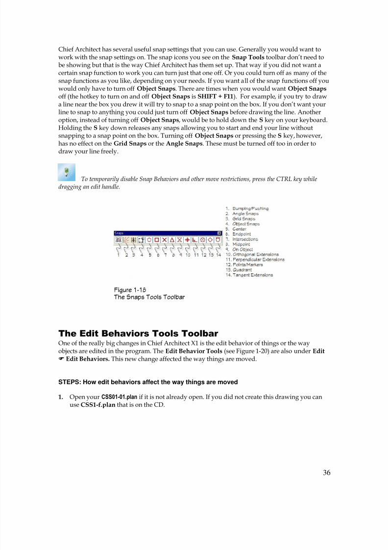
The Snap Tools Toolbar
The Snap Tools toolbar (see Figure 1-18) is a toolbar that you will work with often. When youfirst begin using Chief Architect all of the snaps will be on by default. The first tool on thistoolbar is the Bumping/Pushing tool. This was introduced in Chief Architect X1.
Figure 1-16 The Display Tools Toolbar

8/4/2019 Chapter 1 Chief Architect
http://slidepdf.com/reader/full/chapter-1-chief-architect 33/54
33
STEPS: Working with the Bumping/Pushing function
1. Click the Cabinet Tools icon on the Architectural Tools toolbar. Move the cursor tothe middle area of your building and left click to place the cabinet. Press the SPACE bar on
your keyboard to engage the Select Objects tool.
2. Select the cabinet. Notice the little square in themiddle of the cabinet? This is the center edit handle for the cabinet.
3. Place the cursor over the top of this edit handle.The cursor will change to a4-way arrow symbol. Clickthe left mouse button anddrag the cabinet to the rightwall of the building. When
you get to the wall thecabinet will stop. If youcontinue to try and drag thecabinet to the right and you drag far enough it willeventually go through the wall. But when you first bumped against the wall the cabinetstopped.
4. Move the cabinet back to the middle part of the building. Click the Bumping/Pushing tool. Now click and drag the cabinet to the right wall. This time the cabinet will go right
through the wall without stopping. Click the Bumping/Pushing tool again to turn it
back on.
5. Click the Save tool button to save your drawing.
In prior versions of Chief Architect (prior to Chief Architect X1) you had to push the CTRL key tobe able to drag a cabinet through a wall. In the earlier versions unless you pressed the CTRL keythe cabinet would stop at the wall.
The next tool is the Angle Snaps button. By default, with this tool on, Chief Architect will snap to
a point in 15° increments. This can be changed to 7 ½°. If this tool is turned off you can snap toany angle. This is for everything in your plan; walls, doors, cabinets, etc.
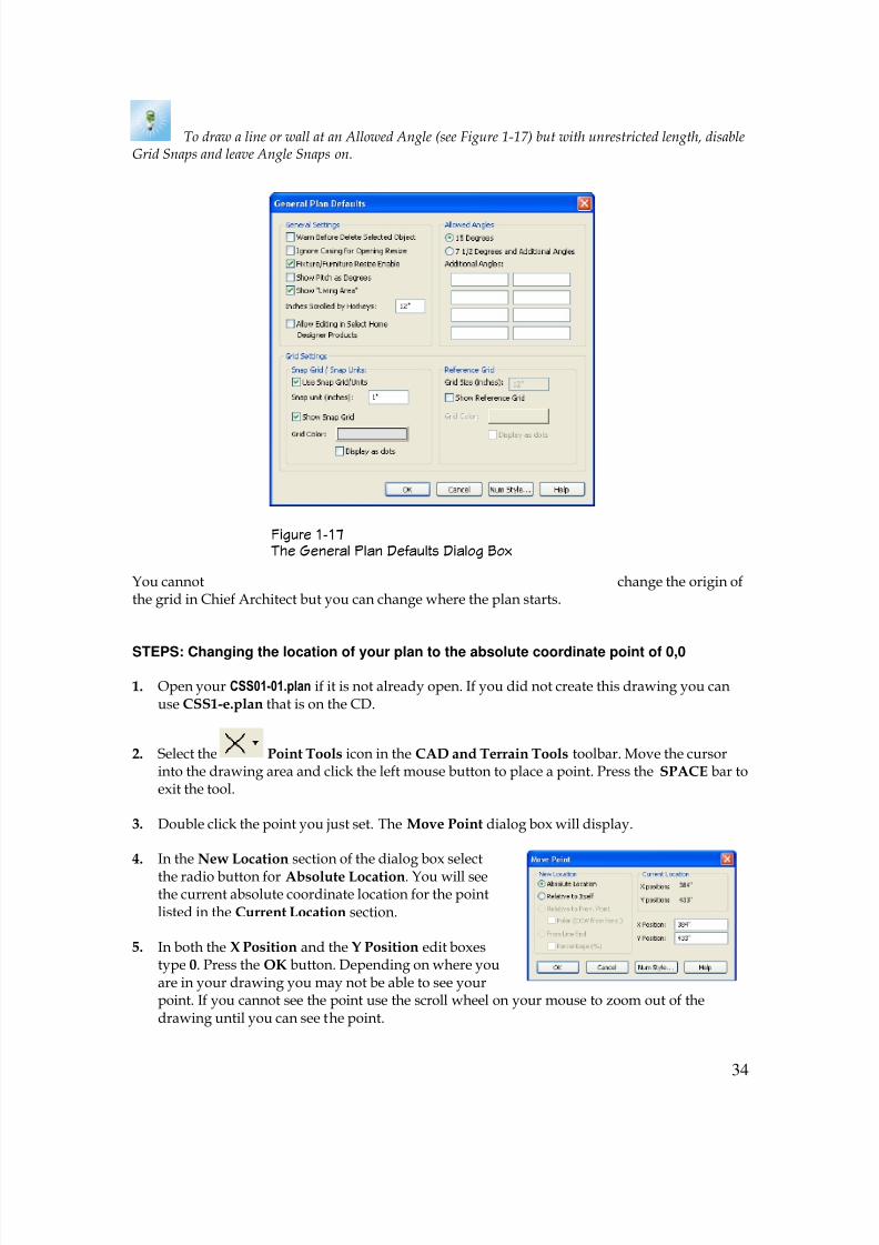
If you don’t want to be snapping to a grid turn the Grid Snaps tool button off. By default ChiefArchitect has a grid that you can snap to. You can adjust the size of the grid snaps and the size ofthe grid as it appears on your screen using the General Plan Defaults dialog box (see Figure 1-
17). You can display this dialog box by double clicking the Select Objects tool. In the GridSetting section you can change the snap units by double clicking the number showing in the
Snap unit (inches) edit list box. By default the grid snap is set to snap at every 1”. For a smallergrid snap you can change this to ½”, ¼”, 1/16”, or whatever.
8/4/2019 Chapter 1 Chief Architect
http://slidepdf.com/reader/full/chapter-1-chief-architect 34/54
34
To draw a line or wall at an Allowed Angle (see Figure 1-17) but with unrestricted length, disableGrid Snaps and leave Angle Snaps on.
You cannot change the origin ofthe grid in Chief Architect but you can change where the plan starts.
STEPS: Changing the location of your plan to the absolute coordinate point of 0,0
1. Open your CSS01-01.plan if it is not already open. If you did not create this drawing you canuse CSS1-e.plan that is on the CD.
2. Select the Point Tools icon in the CAD and Terrain Tools toolbar. Move the cursorinto the drawing area and click the left mouse button to place a point. Press the SPACE bar toexit the tool.
3. Double click the point you just set. The Move Point dialog box will display.
4. In the New Location section of the dialog box select
the radio button for Absolute Location. You will seethe current absolute coordinate location for the pointlisted in the Current Location section.
5. In both the X Position and the Y Position edit boxestype 0. Press the OK button. Depending on where youare in your drawing you may not be able to see yourpoint. If you cannot see the point use the scroll wheel on your mouse to zoom out of thedrawing until you can see the point.
Figure 1-17 The General Plan Defaults Dialog Box

8/4/2019 Chapter 1 Chief Architect
http://slidepdf.com/reader/full/chapter-1-chief-architect 35/54
35
This is the point where you would probably want to start a plan from. Placing the point at theabsolute coordinate of 0, 0 puts you right in the center of the grid. Maybe you want to move over½” or some other value. This is how you can use the snap setting for the grid. Find the origin ofthe grid and work with it from there.
Object Snaps is the next snap function on the Snap Tools toolbar. You will find that Chief
Architect X1 and X2 now have very good snap functions. Later in the book you will find out indetail how to snap things together.
STEPS: Working with snaps
1. Zoom back into the box that you drew earlier.
2. A tool must be selected in order for the snap functions to work. Select the Point Tools icon in the CAD and Terrain Tools toolbar.
3. Move your cursor to the box you drew earlier. With the cursortrace the perimeter of the box. Notice the red symbols thatdisplay as you move the cursor around the perimeter. Thesymbols represent the snap function that will be applied if youclick the mouse button.
4. Move the cursor to the middle of the top line. A little red triangle will display. This is theMid Point snap indicator. Move the cursor to one of the corners of the box. A red square willdisplay. This is the Endpoint snap indicator. As you move from the corner towards themidpoint of a side an hourglass symbol will display. This is the On Object snap indicator.
5. Place the cursor on the midpoint of the top line of the box. You will know you are at the
midpoint when the Mid Point snap indicator displays. Move your cursor down and a dashedline will follow it. When you are near the center of the box move thecursor to the right side of the box. When you see the Mid Point snapindicator display for the right side move the cursor back towards thecenter of the box. Again, a dashed line follows your cursor. Whenyou are near the center of the box a vertical line extending from themidpoint of the top line of the box will intersect the line extendingfrom the midpoint of the right line of the box. Where these two linesmeet is the exact center of the box. Click the mouse button to snap apoint to this exact center of the box. This is a result of theOrthogonal Extensions snap setting.
6.
Move the cursor to the top right corner of the box until the Endpoint snap indicator displays.Now move the cursor to the right. A line follows the cursor allowing you to keep in an exactline with the top line of the box. Click to snap a point. Go back to the corner. Move the cursorupwards and again a line follows the cursor allowing you to keep in line, this time with theright line of the box. Click to snap another point.
7. Click the Save tool button to save your drawing.
8/4/2019 Chapter 1 Chief Architect
http://slidepdf.com/reader/full/chapter-1-chief-architect 36/54
36
Chief Architect has several useful snap settings that you can use. Generally you would want towork with the snap settings on. The snap icons you see on the Snap Tools toolbar don’t need tobe showing but that is the way Chief Architect has them set up. That way if you did not want acertain snap function to work you can turn just that one off. Or you could turn off as many of thesnap functions as you like, depending on your needs. If you want all of the snap functions off youwould only have to turn off Object Snaps. There are times when you would want Object Snaps
off (the hotkey to turn on and off Object Snaps is SHIFT + F11). For example, if you try to drawa line near the box you drew it will try to snap to a snap point on the box. If you don’t want yourline to snap to anything you could just turn off Object Snaps before drawing the line. Anotheroption, instead of turning off Object Snaps, would be to hold down the S key on your keyboard.Holding the S key down releases any snaps allowing you to start and end your line withoutsnapping to a snap point on the box. Turning off Object Snaps or pressing the S key, however,has no effect on the Grid Snaps or the Angle Snaps. These must be turned off too in order todraw your line freely.
To temporarily disable Snap Behaviors and other move restrictions, press the CTRL key whiledragging an edit handle.
The Edit Behaviors Tools Toolbar One of the really big changes in Chief Architect X1 is the edit behavior of things or the wayobjects are edited in the program. The Edit Behavior Tools (see Figure 1-20) are also under Edit Edit Behaviors. This new change affected the way things are moved.
STEPS: How edit behaviors affect the way things are moved
1. Open your CSS01-01.plan if it is not already open. If you did not create this drawing you canuse CSS1-f.plan that is on the CD.
Figure 1-18 The Snaps Tools Toolbar
8/4/2019 Chapter 1 Chief Architect
http://slidepdf.com/reader/full/chapter-1-chief-architect 37/54
37
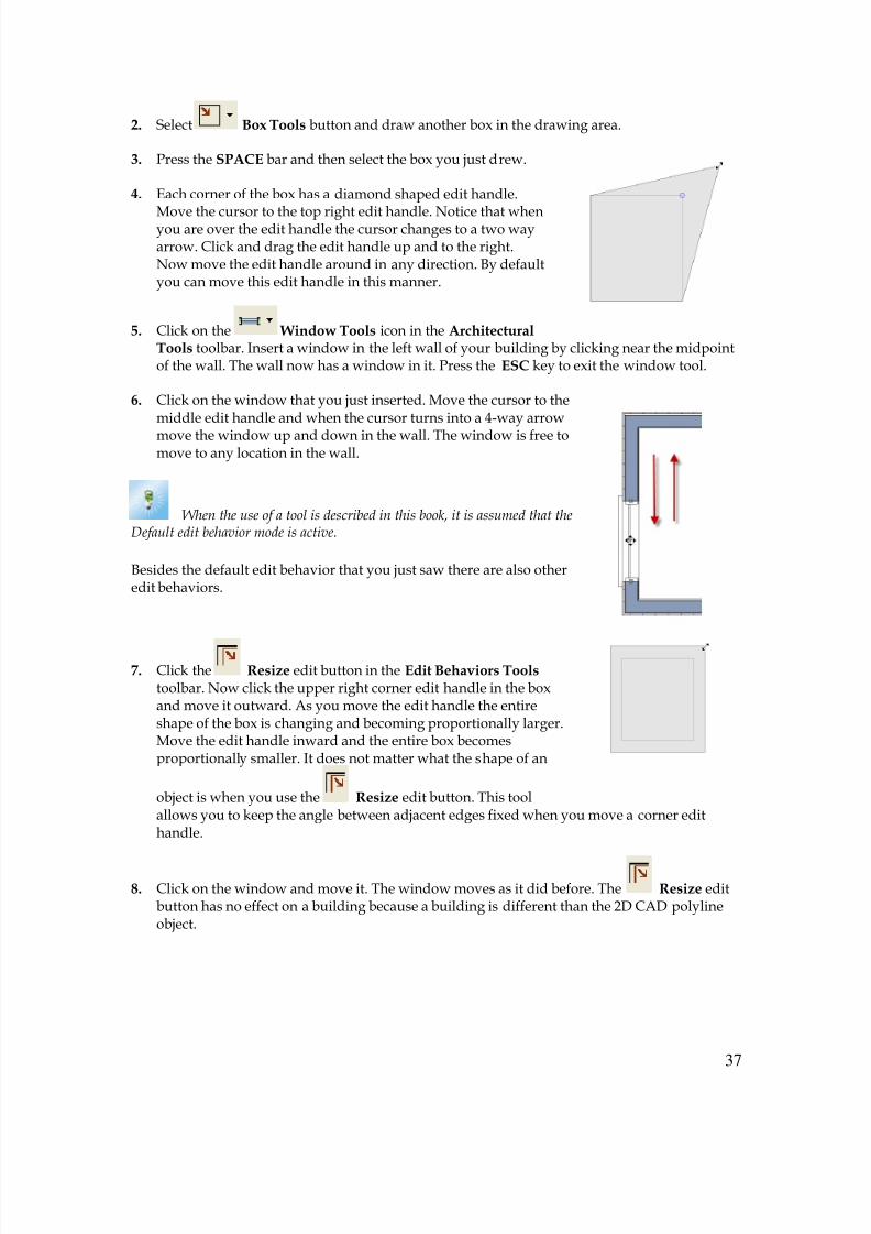
2. Select Box Tools button and draw another box in the drawing area.
3. Press the SPACE bar and then select the box you just drew.
4. Each corner of the box has a diamond shaped edit handle.
Move the cursor to the top right edit handle. Notice that whenyou are over the edit handle the cursor changes to a two wayarrow. Click and drag the edit handle up and to the right.Now move the edit handle around in any direction. By defaultyou can move this edit handle in this manner.
5. Click on the Window Tools icon in the ArchitecturalTools toolbar. Insert a window in the left wall of your building by clicking near the midpointof the wall. The wall now has a window in it. Press the ESC key to exit the window tool.
6. Click on the window that you just inserted. Move the cursor to themiddle edit handle and when the cursor turns into a 4-way arrow
move the window up and down in the wall. The window is free tomove to any location in the wall.
When the use of a tool is described in this book, it is assumed that theDefault edit behavior mode is active.
Besides the default edit behavior that you just saw there are also otheredit behaviors.
7. Click the Resize edit button in the Edit Behaviors Tools toolbar. Now click the upper right corner edit handle in the boxand move it outward. As you move the edit handle the entireshape of the box is changing and becoming proportionally larger.Move the edit handle inward and the entire box becomesproportionally smaller. It does not matter what the shape of an
object is when you use the Resize edit button. This toolallows you to keep the angle between adjacent edges fixed when you move a corner edithandle.
8. Click on the window and move it. The window moves as it did before. The Resize editbutton has no effect on a building because a building is different than the 2D CAD polylineobject.
8/4/2019 Chapter 1 Chief Architect
http://slidepdf.com/reader/full/chapter-1-chief-architect 38/54
38
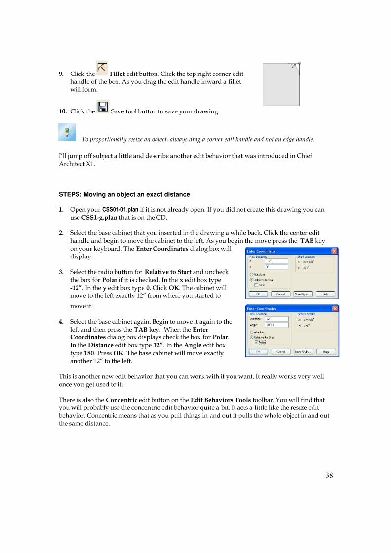
9. Click the Fillet edit button. Click the top right corner edithandle of the box. As you drag the edit handle inward a filletwill form.
10. Click the Save tool button to save your drawing.
To proportionally resize an object, always drag a corner edit handle and not an edge handle.
I’ll jump off subject a little and describe another edit behavior that was introduced in ChiefArchitect X1.
STEPS: Moving an object an exact distance
1. Open your CSS01-01.plan if it is not already open. If you did not create this drawing you canuse CSS1-g.plan that is on the CD.
2. Select the base cabinet that you inserted in the drawing a while back. Click the center edithandle and begin to move the cabinet to the left. As you begin the move press the TAB keyon your keyboard. The Enter Coordinates dialog box willdisplay.
3. Select the radio button for Relative to Start and uncheckthe box for Polar if it is checked. In the x edit box type
-12”. In the y edit box type 0. Click OK. The cabinet willmove to the left exactly 12” from where you started to
move it.
4. Select the base cabinet again. Begin to move it again to theleft and then press the TAB key. When the EnterCoordinates dialog box displays check the box for Polar.In the Distance edit box type 12”. In the Angle edit boxtype 180. Press OK. The base cabinet will move exactlyanother 12” to the left.
This is another new edit behavior that you can work with if you want. It really works very well
once you get used to it.
There is also the Concentric edit button on the Edit Behaviors Tools toolbar. You will find thatyou will probably use the concentric edit behavior quite a bit. It acts a little like the resize editbehavior. Concentric means that as you pull things in and out it pulls the whole object in and outthe same distance.
8/4/2019 Chapter 1 Chief Architect
http://slidepdf.com/reader/full/chapter-1-chief-architect 39/54
39
STEPS: Working with the Concentric edit behavior
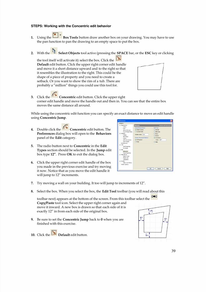
1. Using the Box Tools button draw another box on your drawing. You may have to usethe pan function to pan the drawing to an empty space to put the box.
2. With the Select Objects tool active (pressing the SPACE bar, or the ESC key or clicking
the tool itself will activate it) select the box. Click theDefault edit button. Click the upper right corner edit handleand move it a short distance upward and to the right so thatit resembles the illustration to the right. This could be theshape of a piece of property and you need to create asetback. Or you want to show the rim of a tub. There areprobably a “million” things you could use this tool for.
3. Click the Concentric edit button. Click the upper right
corner edit handle and move the handle out and then in. You can see that the entire boxmoves the same distance all around.
While using the concentric edit function you can specify an exact distance to move an edit handleusing Concentric Jump.
4. Double click the Concentric edit button. ThePreferences dialog box will open to the Behaviors panel of the Edit category.
5. The radio button next to Concentric in the EditTypes section should be selected. In the Jump edit
box type 12”. Press OK to exit the dialog box.
6. Click the upper right corner edit handle of the boxyou made in the previous exercise and try movingit now. Notice that as you move the edit handle itwill jump to 12” increments.
7. Try moving a wall on your building. It too will jump to increments of 12”.
8. Select the box. When you select the box, the Edit Tool toolbar (you will read about this
toolbar next) appears at the bottom of the screen. From this toolbar select the
Copy/Paste tool icon. Select the upper right corner again andmove it inward. A new box is drawn so that each side of it isexactly 12” in from each side of the original box.
9. Be sure to set the Concentric Jump back to 0 when you arefinished with this exercise.
10. Click the Default edit button.
8/4/2019 Chapter 1 Chief Architect
http://slidepdf.com/reader/full/chapter-1-chief-architect 40/54
40
11. Click the Save tool button to save your drawing.
To concentrically resize an object with no restrictions, set the Concentric Jump value on the EditBehaviors panel of the Preferences dialog to zero and turn off Grid Snaps
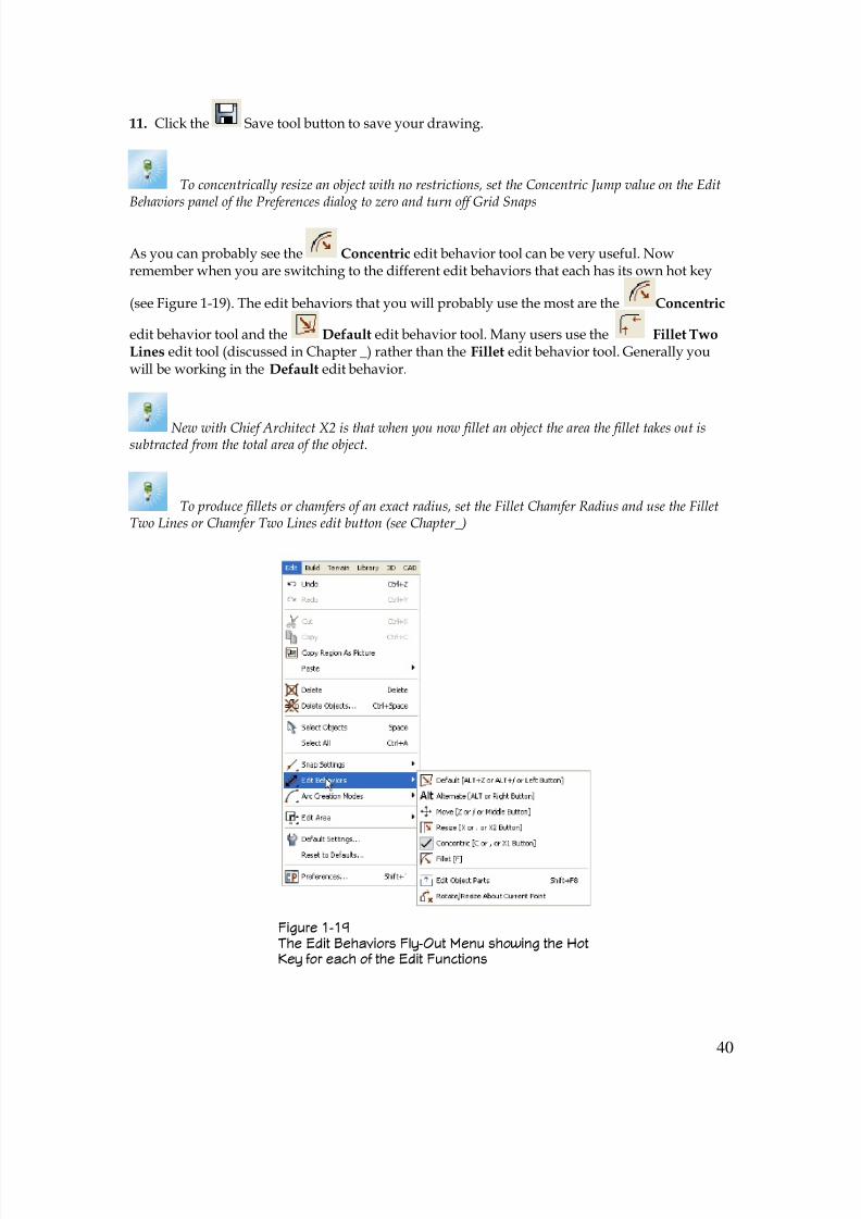
As you can probably see the Concentric edit behavior tool can be very useful. Nowremember when you are switching to the different edit behaviors that each has its own hot key
(see Figure 1-19). The edit behaviors that you will probably use the most are the Concentric
edit behavior tool and the Default edit behavior tool. Many users use the Fillet TwoLines edit tool (discussed in Chapter _) rather than the Fillet edit behavior tool. Generally youwill be working in the Default edit behavior.
New with Chief Architect X2 is that when you now fillet an object the area the fillet takes out issubtracted from the total area of the object.
To produce fillets or chamfers of an exact radius, set the Fillet Chamfer Radius and use the FilletTwo Lines or Chamfer Two Lines edit button (see Chapter_)
Figure 1-19 The Edit Behaviors Fly-Out Menu showing the HotKey for each of the Edit Functions
8/4/2019 Chapter 1 Chief Architect
http://slidepdf.com/reader/full/chapter-1-chief-architect 41/54
41
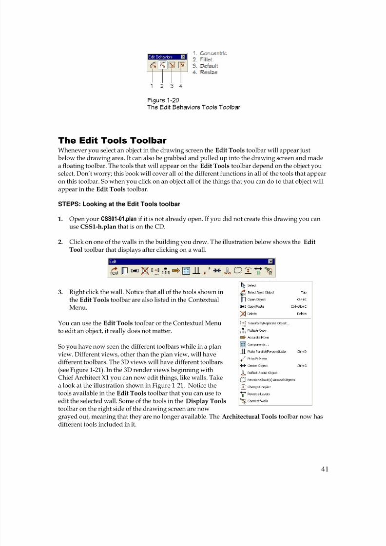
The Edit Tools Toolbar Whenever you select an object in the drawing screen the Edit Tools toolbar will appear justbelow the drawing area. It can also be grabbed and pulled up into the drawing screen and madea floating toolbar. The tools that will appear on the Edit Tools toolbar depend on the object youselect. Don’t worry; this book will cover all of the different functions in all of the tools that appearon this toolbar. So when you click on an object all of the things that you can do to that object will
appear in the Edit Tools toolbar.
STEPS: Looking at the Edit Tools toolbar
1. Open your CSS01-01.plan if it is not already open. If you did not create this drawing you canuse CSS1-h.plan that is on the CD.
2. Click on one of the walls in the building you drew. The illustration below shows the EditTool toolbar that displays after clicking on a wall.
3. Right click the wall. Notice that all of the tools shown inthe Edit Tools toolbar are also listed in the ContextualMenu.
You can use the Edit Tools toolbar or the Contextual Menuto edit an object, it really does not matter.
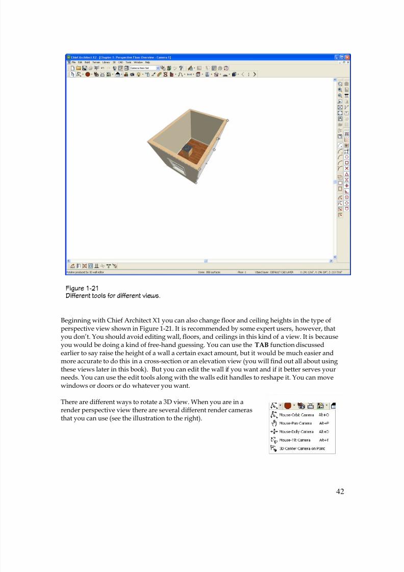
So you have now seen the different toolbars while in a planview. Different views, other than the plan view, will havedifferent toolbars. The 3D views will have different toolbars(see Figure 1-21). In the 3D render views beginning withChief Architect X1 you can now edit things, like walls. Takea look at the illustration shown in Figure 1-21. Notice thetools available in the Edit Tools toolbar that you can use toedit the selected wall. Some of the tools in the Display Tools toolbar on the right side of the drawing screen are nowgrayed out, meaning that they are no longer available. The Architectural Tools toolbar now hasdifferent tools included in it.
Figure 1-20 The Edit Behaviors Tools Toolbar
8/4/2019 Chapter 1 Chief Architect
http://slidepdf.com/reader/full/chapter-1-chief-architect 42/54
42
Figure 1-21 Different tools for different views.
Beginning with Chief Architect X1 you can also change floor and ceiling heights in the type ofperspective view shown in Figure 1-21. It is recommended by some expert users, however, thatyou don’t. You should avoid editing wall, floors, and ceilings in this kind of a view. It is becauseyou would be doing a kind of free-hand guessing. You can use the TAB function discussedearlier to say raise the height of a wall a certain exact amount, but it would be much easier andmore accurate to do this in a cross-section or an elevation view (you will find out all about usingthese views later in this book). But you can edit the wall if you want and if it better serves yourneeds. You can use the edit tools along with the walls edit handles to reshape it. You can movewindows or doors or do whatever you want.
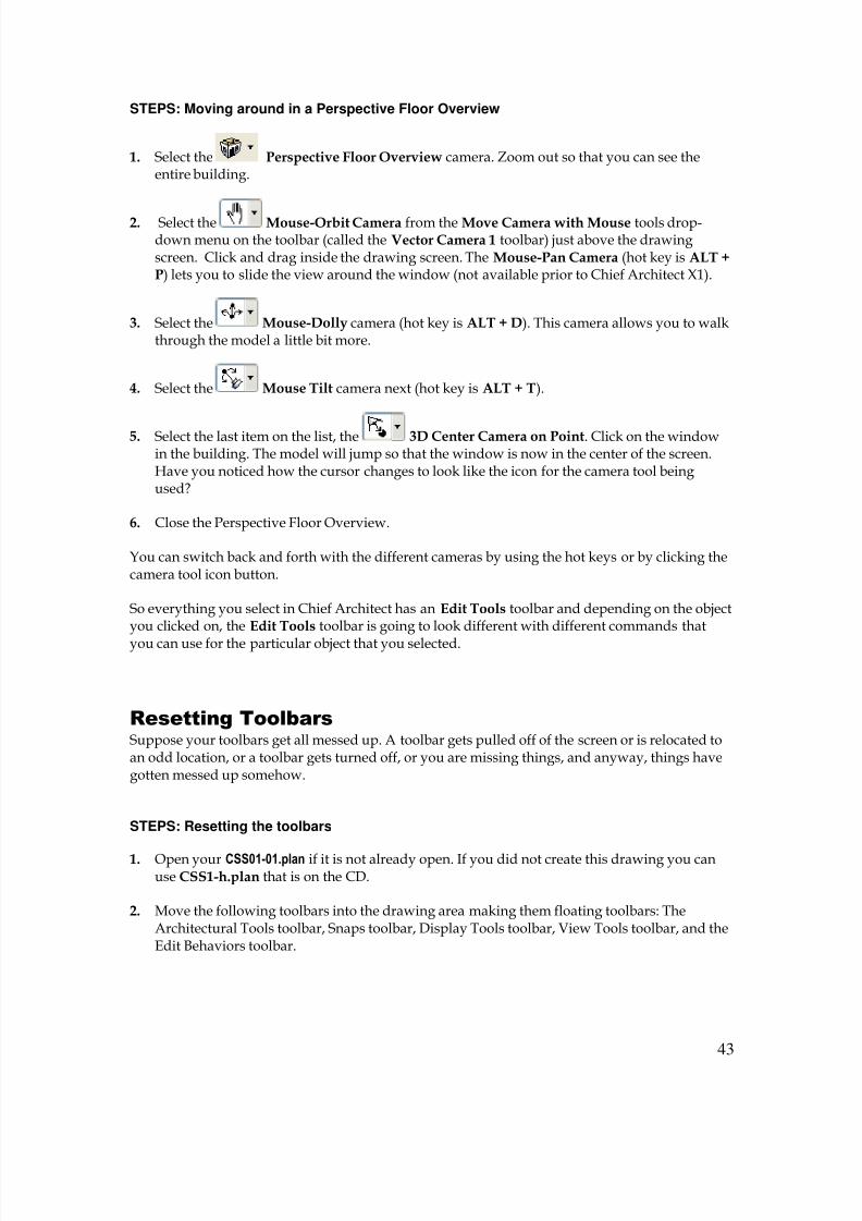
There are different ways to rotate a 3D view. When you are in arender perspective view there are several different render camerasthat you can use (see the illustration to the right).
8/4/2019 Chapter 1 Chief Architect
http://slidepdf.com/reader/full/chapter-1-chief-architect 43/54
43
STEPS: Moving around in a Perspective Floor Overview
1. Select the Perspective Floor Overview camera. Zoom out so that you can see theentire building.
2. Select the Mouse-Orbit Camera from the Move Camera with Mouse tools drop-down menu on the toolbar (called the Vector Camera 1 toolbar) just above the drawingscreen. Click and drag inside the drawing screen. The Mouse-Pan Camera (hot key is ALT +P) lets you to slide the view around the window (not available prior to Chief Architect X1).
3. Select the Mouse-Dolly camera (hot key is ALT + D). This camera allows you to walkthrough the model a little bit more.
4. Select the Mouse Tilt camera next (hot key is ALT + T).
5. Select the last item on the list, the 3D Center Camera on Point. Click on the windowin the building. The model will jump so that the window is now in the center of the screen.Have you noticed how the cursor changes to look like the icon for the camera tool beingused?
6. Close the Perspective Floor Overview.
You can switch back and forth with the different cameras by using the hot keys or by clicking thecamera tool icon button.
So everything you select in Chief Architect has an Edit Tools toolbar and depending on the objectyou clicked on, the Edit Tools toolbar is going to look different with different commands that
you can use for the particular object that you selected.
Resetting Toolbars
Suppose your toolbars get all messed up. A toolbar gets pulled off of the screen or is relocated toan odd location, or a toolbar gets turned off, or you are missing things, and anyway, things havegotten messed up somehow.
STEPS: Resetting the toolbars
1. Open your CSS01-01.plan if it is not already open. If you did not create this drawing you canuse CSS1-h.plan that is on the CD.
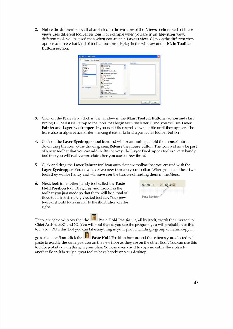
2. Move the following toolbars into the drawing area making them floating toolbars: TheArchitectural Tools toolbar, Snaps toolbar, Display Tools toolbar, View Tools toolbar, and theEdit Behaviors toolbar.

8/4/2019 Chapter 1 Chief Architect
http://slidepdf.com/reader/full/chapter-1-chief-architect 44/54
44
3. Select Tools Toolbars & Hotkeys Customize Toolbars. Or you could right-click on atool icon and select Customize Toolbars from the drop-down menu that appears. TheToolbar Customization dialog box will display.
4. Go to the Toolbar tab. In the Views section youwill see all of the different types of views. On
the right side is the Reset Toolbars button. Clickthe Reset Toolbars button. You will get a
Warning dialog box asking “Are you sure youwant to restore the default toolbars.” Click OK.Chief Architect will reload the original toolbarsfor the configuration that you selected (to seewhat configuration is selected go to the Configuration tab) that were present when you firstopened the program. If you have been following the exercises the Extended ToolsConfiguration will have been selected as the current configuration for your toolbars.Remember you would only want to do this as a last resort to fix a mess as any othercustomization you have done will be lost. Since you have not yet done any customizationyou don’t need to worry.
5. Select Close to exit the dialog box.
Create Custom Toolbars
You can create your own custom toolbars and tool icons. If you want to have a toolbar that hasthe tools that you use all the time then you would want to create a custom toolbar.
STEPS: Creating a custom toolbar
1. Right click a tool icon and select Customize Toolbars from the drop down menu (also knowas a Context Sensitive Menu, or the Local Menu, or the Short Cut Menu). The ToolbarCustomization dialog box will display.
8/4/2019 Chapter 1 Chief Architect
http://slidepdf.com/reader/full/chapter-1-chief-architect 45/54
45
2. Notice the different views that are listed in the window of the Views section. Each of theseviews uses different toolbar buttons. For example when you are in an Elevation view,different tools will be used than when you are in a Layout view. Click on the different viewoptions and see what kind of toolbar buttons display in the window of the Main ToolbarButtons section.
3. Click on the Plan view. Click in the window in the Main Toolbar Buttons section and starttyping L. The list will jump to the tools that begin with the letter L and you will see LayerPainter and Layer Eyedropper. If you don’t then scroll down a little until they appear. Thelist is also in alphabetical order, making it easier to find a particular toolbar button.
4. Click on the Layer Eyedropper tool icon and while continuing to hold the mouse buttondown drag the icon to the drawing area. Release the mouse button. The icon will now be partof a new toolbar that you can add to. By the way, the Layer Eyedropper tool is a very handytool that you will really appreciate after you use it a few times.
5. Click and drag the Layer Painter tool icon onto the new toolbar that you created with theLayer Eyedropper. You now have two new icons on your toolbar. When you need these two
tools they will be handy and will save you the trouble of finding them in the Menu.
6. Next, look for another handy tool called the PasteHold Position tool. Drag it up and drop it in thetoolbar you just made so that there will be a total ofthree tools in this newly created toolbar. Your newtoolbar should look similar to the illustration on theright.
There are some who say that the Paste Hold Position is, all by itself, worth the upgrade toChief Architect X1 and X2. You will find that as you use the program you will probably use this
tool a lot. With this tool you can take anything in your plan, including a group of items, copy it,
go to the next floor, click the Paste Hold Position button, and those items you selected willpaste to exactly the same position on the new floor as they are on the other floor. You can use thistool for just about anything in your plan. You can even use it to copy an entire floor plan toanother floor. It is truly a great tool to have handy on your desktop.

8/4/2019 Chapter 1 Chief Architect
http://slidepdf.com/reader/full/chapter-1-chief-architect 46/54
46
As you can see it is pretty easy to add tools to your desktop. If you have or discover other toolsthat you use often, using the Toolbar Customization dialog box will make it simple to place thetool on your desktop.
You can create a toolbar that has a group of appliances that you use all the time, such as a showeror a tub, etc.
STEPS: Creating a toolbar with a group of appliances from the library
1. Go to the Main Toolbar Buttons section of the Tools tab of the Toolbars Customization dialog box (see steps 1-3 of the previous exercise). Type Pl and click on Place Library Object.What you want to do is place something from the Chief Architect library that will beavailable to you all the time.
2. Pull the Place Library icon onto the screen someplace. Pull the same icon onto the newtoolbar twice more so that there is a total of 3 Place Library icons on the new toolbar.
3.
Start a different toolbar by pulling the Place Library icon onto the screen away from the toolbar you justcreated. Place a total of 3 Place Library icons on this
one as well.
4. Click the Close button to close the dialog box.
5. Click on one of the Place Library icon that you placed. TheLibrary Object Button Specification dialog box will display.
6. Click the Library button in the Library Object section. TheSelect Library Object (see Figure 1-22) dialog box will
display.
7. Click on Standard (right) for the Standard Tubs option in the Bathtub subcategory underFixtures, which is in the Architectural category.Clicking on the small + sign in front of eachcategory will display the items in each category.
8. Click OK and the picture of the bathtub appearsin the window of the Library Object ButtonSpecification dialog box.
9. Highlight Automatic 1 and press the OK button.
Figure 1-22 Select Library Object dialog box
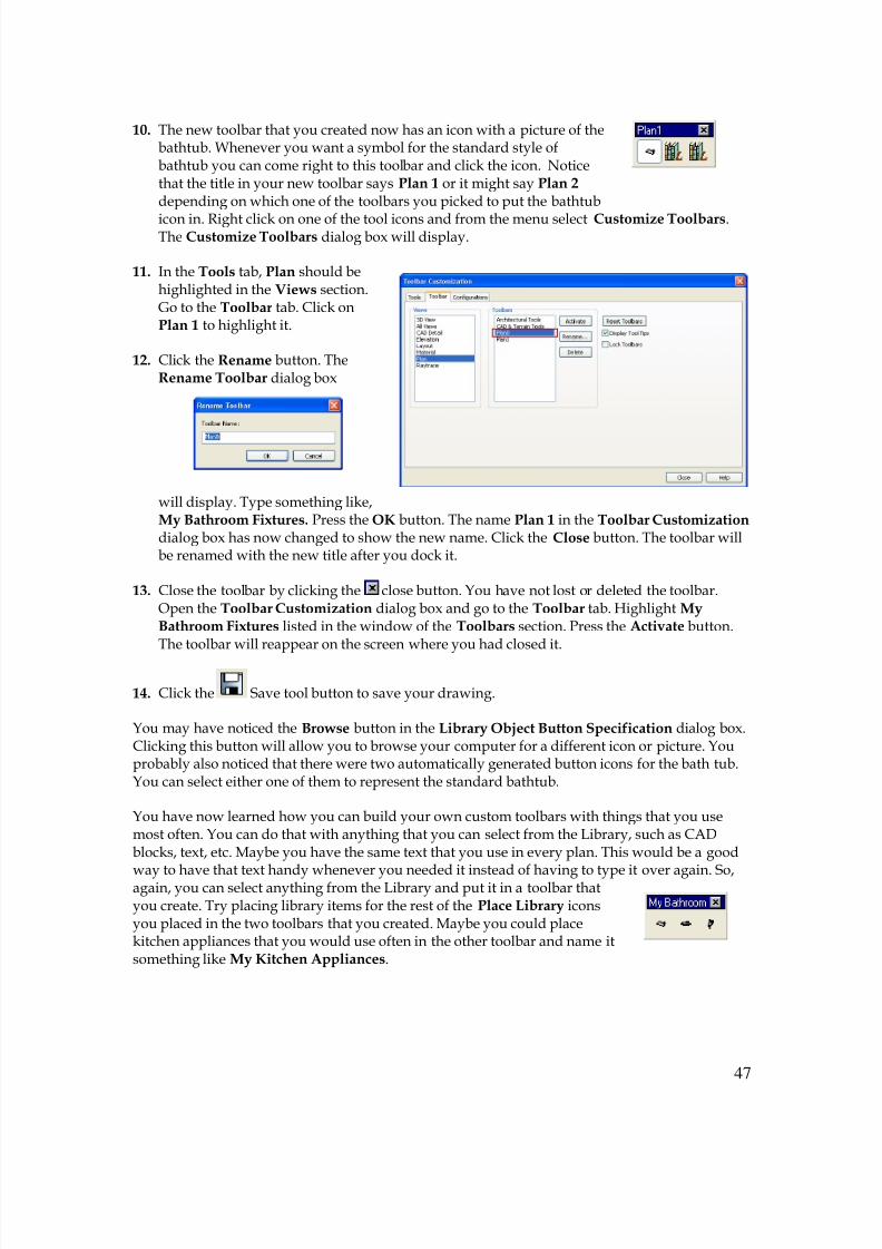
8/4/2019 Chapter 1 Chief Architect
http://slidepdf.com/reader/full/chapter-1-chief-architect 47/54
47
10. The new toolbar that you created now has an icon with a picture of thebathtub. Whenever you want a symbol for the standard style ofbathtub you can come right to this toolbar and click the icon. Noticethat the title in your new toolbar says Plan 1 or it might say Plan 2 depending on which one of the toolbars you picked to put the bathtub
icon in. Right click on one of the tool icons and from the menu select Customize Toolbars.The Customize Toolbars dialog box will display.
11. In the Tools tab, Plan should behighlighted in the Views section.Go to the Toolbar tab. Click onPlan 1 to highlight it.
12. Click the Rename button. TheRename Toolbar dialog box
will display. Type something like,My Bathroom Fixtures. Press the OK button. The name Plan 1 in the Toolbar Customization dialog box has now changed to show the new name. Click the Close button. The toolbar willbe renamed with the new title after you dock it.
13. Close the toolbar by clicking the close button. You have not lost or deleted the toolbar.Open the Toolbar Customization dialog box and go to the Toolbar tab. Highlight MyBathroom Fixtures listed in the window of the Toolbars section. Press the Activate button.The toolbar will reappear on the screen where you had closed it.
14. Click the Save tool button to save your drawing.
You may have noticed the Browse button in the Library Object Button Specification dialog box.Clicking this button will allow you to browse your computer for a different icon or picture. Youprobably also noticed that there were two automatically generated button icons for the bath tub.You can select either one of them to represent the standard bathtub.
You have now learned how you can build your own custom toolbars with things that you usemost often. You can do that with anything that you can select from the Library, such as CADblocks, text, etc. Maybe you have the same text that you use in every plan. This would be a good
way to have that text handy whenever you needed it instead of having to type it over again. So,again, you can select anything from the Library and put it in a toolbar thatyou create. Try placing library items for the rest of the Place Library iconsyou placed in the two toolbars that you created. Maybe you could placekitchen appliances that you would use often in the other toolbar and name itsomething like My Kitchen Appliances.
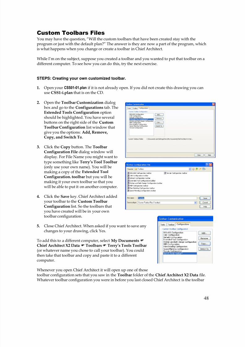
8/4/2019 Chapter 1 Chief Architect
http://slidepdf.com/reader/full/chapter-1-chief-architect 48/54
48
Custom Toolbars Files
You may have the question, “Will the custom toolbars that have been created stay with theprogram or just with the default plan?” The answer is they are now a part of the program, whichis what happens when you change or create a toolbar in Chief Architect.
While I’m on the subject, suppose you created a toolbar and you wanted to put that toolbar on adifferent computer. To see how you can do this, try the next exercise.
STEPS: Creating your own customized toolbar.
1. Open your CSS01-01.plan if it is not already open. If you did not create this drawing you canuse CSS1-i.plan that is on the CD.
2. Open the Toolbar Customization dialogbox and go to the Configurations tab. TheExtended Tools Configuration optionshould be highlighted. You have several
buttons on the right side of the CustomToolbar Configuration list window thatgive you the options: Add, Remove,Copy, and Switch To.
3. Click the Copy button. The ToolbarConfiguration File dialog window willdisplay. For File Name you might want to
type something like Terry’s Tool Toolbar (only use your own name). You will bemaking a copy of the Extended ToolConfiguration. toolbar but you will be
making it your own toolbar so that youwill be able to put it on another computer.
4. Click the Save key. Chief Architect addedyour toolbar to the Custom ToolbarConfiguration list. So the toolbars thatyou have created will be in your owntoolbar configuration.
5. Close Chief Architect. When asked if you want to save anychanges to your drawing, click Yes.
To add this to a different computer, select My Documents Chief Architect X2 Data Toolbars Terry’s Tools Toolbar (or whatever name you chose to call your toolbar). You couldthen take that toolbar and copy and paste it to a differentcomputer.
Whenever you open Chief Architect it will open up one of thosetoolbar configuration sets that you saw in the Toolbar folder of the Chief Architect X2 Data file.Whatever toolbar configuration you were in before you last closed Chief Architect is the toolbar

8/4/2019 Chapter 1 Chief Architect
http://slidepdf.com/reader/full/chapter-1-chief-architect 49/54
49
configuration you will see when you reopen Chief Architect. In this case if you went to theConfiguration tab of the Toolbar Customization dialog box the toolbar configuration that you
just named would be highlighted and that would be the configuration you would see on yourscreen.
You could set up different materials, different colors, and literally hundreds of pallets of toolbars
on your computer if you really wanted to.
Hotkeys
Using a keyboard shortcut, or hotkey, is a convenient way to execute commands in ChiefArchitect. Many people prefer to keep their hands on thekeyboard rather than going back and forth from thekeyboard to the mouse. Many of the Chief Architect toolshave a keyboard shortcut, or hotkey, associated with them. Ifa tool has a hotkey it will be listed to the right of the tool’sname in the menu. Not all of the keyboard shortcuts are very intuitive and so you will need to dosome memory work. Later, in this section, I will show you how to print a list of all the hotkeys
being utilized in Chief Architect. If you start learning the keyboard shortcuts and using them itwill save you some time. Hotkeys are new to Chief Architect X1 and were not available inprevious versions of Chief Architect. In order to use a hotkey, all you have to do is press the appropriate key or combination of keyson your keyboard. This will select the tool you want to use instead of selecting the menu item orclicking the toolbar button. For example, pressing the CTRL key and then the Z key will executethe Undo command.
When you get to working on a plan and the plan starts to grow every time you bring up a 3Dview your computer can take a while to create the view. Of course how long this will take willdepend on your computer. Chief Architect has a function that allows you to use low detail when
bringing up a 3D view. Using low detail will make a big difference in how fast your computercan generate the view. For example look at the render view of the house in Figure 1.2. This wasdone in low detail. Notice how everything looks boxy; the columns are just straight boxes. So a
nice hotkey to have would be for the function Toggle Low Detail Mode. You can then usethe hotkey to quickly locate just the right view you want in a render view. Chief Architect storesa file for hotkeys on your hard drive. There is a file for the icons also.

8/4/2019 Chapter 1 Chief Architect
http://slidepdf.com/reader/full/chapter-1-chief-architect 50/54

8/4/2019 Chapter 1 Chief Architect
http://slidepdf.com/reader/full/chapter-1-chief-architect 51/54
51
to generate a 6 sided box. Chief Architect can then pop the view right out and you can rotateit and get right to the view that you are looking for.
7.7.7.7. Click the OK button to close the dialog box.
Now every time you bring up a 3D view you can quickly rotate it to the position you want, then
press the ALT + 1 hot key and the view is rendered into high detail. This will save you a lot oftime.
If you noticed, many of the functions you saw listed in Command window of the CustomizeHotkey dialog box are not assigned any hot keys. You may, early on, want to assign hot keys tosome of these functions. You may also want to change some of the hotkey assignments so thatthey are easier for you to remember.
In the Tool Available In section of the Customize Hotkeys dialog box is a list of the view typesthat the tool can be used in. A description of the tool is listed in the Tool Description section. Youcan remove the hotkey for any command by selecting the command and clicking the Removebutton.
Nearly all commands can be assigned custom hotkeys; however, a few cannot. Delete and Enter Coordinates are two notable examples.
Create a Hot Key List
One of the chief disadvantages to using hotkey is trying to remember them all. Chief Architecthas included a way to create a list containing all of the hotkeys. This list can be printed and thenused as a reference to aid you in using the hotkeys. Once you have used a hotkey enough timesyou will remember it.
STEPS: Creating a list of hotkeys
1. Select Tools Toolbars & Hotkeys Create Hotkey List. The Save Hotkey List File dialogbox will display. This is a standard Save dialog box.
2. In the Save In drop-down list box finda convenient location for the hotkeylist. In the File Name edit box give thefile a name, such as, “CA HotkeyList”. Click the Save button.
3. Find the location that you just savedthe hotkey list and open it. Notice thatthe list is quite long. Also notice thatthe hotkey you created for the BoxTools-Cross Box is listed. You can now print this list.
8/4/2019 Chapter 1 Chief Architect
http://slidepdf.com/reader/full/chapter-1-chief-architect 52/54
52
The ESC Key as a Hotkey
The ESC key has a special function introduced in Chief Architect X2. Using the ESC key as ahotkey, you have the ability to restore previous commands. To see how this works try this nextexercise.
STEPS: Using the ESC key function.
1. Select the Base Cabinet tool and click in a blank drawing area to place a base cabinet.
2. Select the Wall Cabinet tool and place it in the drawing next to the base cabinet.
3. Select the Full Height cabinet tool and place it near the other two cabinets.
4. After placing the full height cabinet Chief Architect is waiting for you to place another fullheight cabinet unless you select a different tool. Press the ESC key on your keyboard. You areswitched back to the wall cabinet command, which was the previous command. You can nowplace another wall cabinet. If you press the ESC key again you are switched back to the nextprevious command, which was the base cabinet command.
5. Press SHIFT + ESC. You now go forward to the wall cabinet command. Press SHIFT+ESC again to go forward another command, which is the full height cabinet command.
6. Select the Select Objects tool and use this tool to select the base cabinet. Press the ESC key. The base cabinet is deselected. Press the ESC key again without selecting anything. Youare switched to the previous command, the full height cabinet command.

8/4/2019 Chapter 1 Chief Architect
http://slidepdf.com/reader/full/chapter-1-chief-architect 53/54
53

8/4/2019 Chapter 1 Chief Architect
http://slidepdf.com/reader/full/chapter-1-chief-architect 54/54