the chief architect user interface 1x2-webinar-series.s3.amazonaws.com/chapter 1.pdf1 the chief...
TRANSCRIPT
1
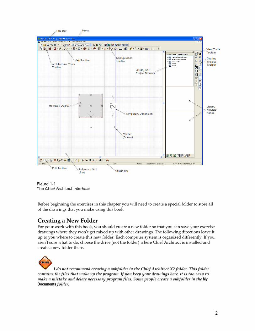
The Chief Architect User Interface You have installed Chief Architect X2 on your computer. It will look something like Figure 1-1. In this first chapter you will get a good look at the interface of Chief Architect (when I say Chief Architect I’m referring to Chief Architect X2). You will learn about the different parts, and the different toolbars. There will be a section on preferences and defaults. The chapter will include everything you will need to know to get set up and get started with the program. In this chapter, you won’t be drawing much of anything. Instead I will be showing you Chief Architect’s interface. It is important to understand the interface in Chief Architect because if you understand how the program works, how it is thinking, what kind of files is it generating, and where it is that you are storing things, then the process of keeping things straight and working more effectively with Chief Architect will be easier. This book is about Chief Architect X2. If you are still using Chief Architect X1 or Chief Architect X, you will find that there will be some differences. As you get into this book, you may determine that it may be worth the cost to upgrade to X2. Both X1 and X2 are very good programs once you get used to the changes that were made from Chief Architect X. There are some things that are a little more difficult than in some of the previous versions, not many, but just a couple of things. But generally, overall, all the added features and the function make X1 and X2 so much better and easier to use. Just like in any new version you just have to learn the new things and how to use them.
♦ ♦ ♦ ♦ In This Chapter
The Chief Architect User Interface
Start Up Screen Options
Using the Help Options
Getting Bonus Content
Toolbars and Menus
Hot Keys
♦ ♦ ♦ ♦
1
CHAPTER
© 2009 Terry Munson, All Rights Reserved.
2
Before beginning the exercises in this chapter you will need to create a special folder to store all of the drawings that you make using this book.
Creating a New Folder For your work with this book, you should create a new folder so that you can save your exercise drawings where they won’t get mixed up with other drawings. The following directions leave it up to you where to create this new folder. Each computer system is organized differently. If you aren’t sure what to do, choose the drive (not the folder) where Chief Architect is installed and create a new folder there.
I do not recommend creating a subfolder in the Chief Architect X2 folder. This folder contains the files that make up the program. If you keep your drawings here, it is too easy to make a mistake and delete necessary program files. Some people create a subfolder in the My Documents folder.
������ �� �� ���� ��������� ����� ���
3
STEPS: Creating a new folder
1. Move the mouse cursor down to the bottom of your screen and right-click the Start button.
2. Choose Explore.
3. In the left pane of Windows Explorer, click the drive where you want to create the new folder. If you don’t know where to create the folder, choose the drive where Chief Architect is installed. If you’re on a network, choose the drive that represents your computer.
4. If you want to make a subfolder (a folder within a folder), choose the folder where you want to create the subfolder.
5. From the Explorer menu, choose File ���� New ���� Folder. A new, highlighted folder, named New Folder, appears in the right pane. You may have to scroll down to see it.
6. Type Chief Architect Step By Step for the folder name and press ENTER.
Save all drawings that you create for this book in your Chief Architect Step By Step folder.
Creating a folder for your drawings as described in the previous steps is essential before you go on to exercises in the rest of this book.
Start Up Screen Options
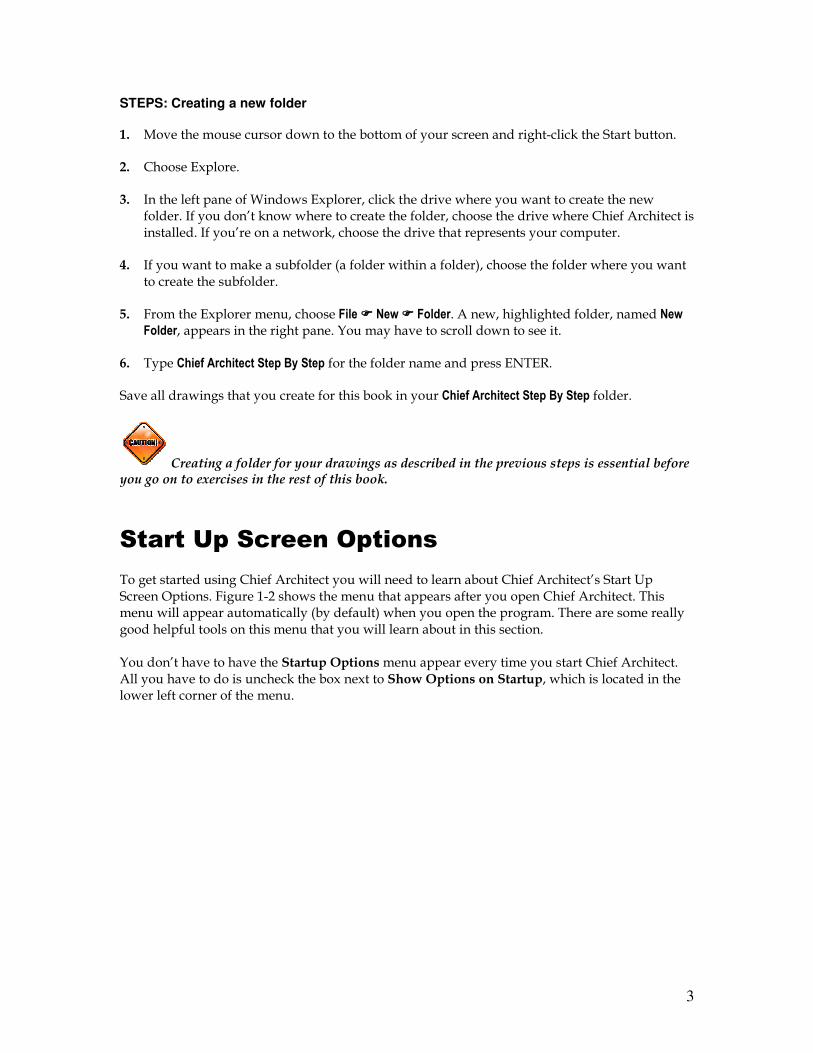
To get started using Chief Architect you will need to learn about Chief Architect’s Start Up Screen Options. Figure 1-2 shows the menu that appears after you open Chief Architect. This menu will appear automatically (by default) when you open the program. There are some really good helpful tools on this menu that you will learn about in this section. You don’t have to have the Startup Options menu appear every time you start Chief Architect. All you have to do is uncheck the box next to Show Options on Startup, which is located in the lower left corner of the menu.
4
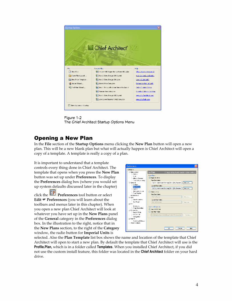
Opening a New Plan In the File section of the Startup Options menu clicking the New Plan button will open a new plan. This will be a new blank plan but what will actually happen is Chief Architect will open a copy of a template. A template is really a copy of a plan. It is important to understand that a template controls every thing done in Chief Architect. The template that opens when you press the New Plan button was set up under Preferences. To display the Preferences dialog box (where you would set up system defaults discussed later in the chapter)
click the Preferences tool button or select Edit ���� Preferences (you will learn about the toolbars and menus later in this chapter). When you open a new plan Chief Architect will look at whatever you have set up in the New Plans panel of the General category in the Preferences dialog box. In the illustration to the right, notice that in the New Plans section, to the right of the Category window, the radio button for Imperial Units is selected. Also the Plan Template list box shows the name and location of the template that Chief Architect will open to start a new plan. By default the template that Chief Architect will use is the Profile.Plan, which is in a folder called Templates. When you installed Chief Architect, if you did not use the custom install feature, this folder was located in the Chief Architect folder on your hard drive.
������ �� �� ���� ��������� ������� ������� ����
5
When you open up a layout template Chief Architect will open up whatever layout template is listed in the Layout Template list box. If nothing is listed there a basic blank layout page will display (you will learn all about layouts in Chapter ____).
You can have a template that you set up listed in this section of the Preferences dialog box and Chief Architect will open it for you when you press the New Plan button.
Did you notice that in the New Plans section that Metric Units are also available? If you were to select the radio dial for Metric Units the Plan Template list box would become available. By default the ProfileM.Plan is listed as the default template. This template has been set up using metric units.
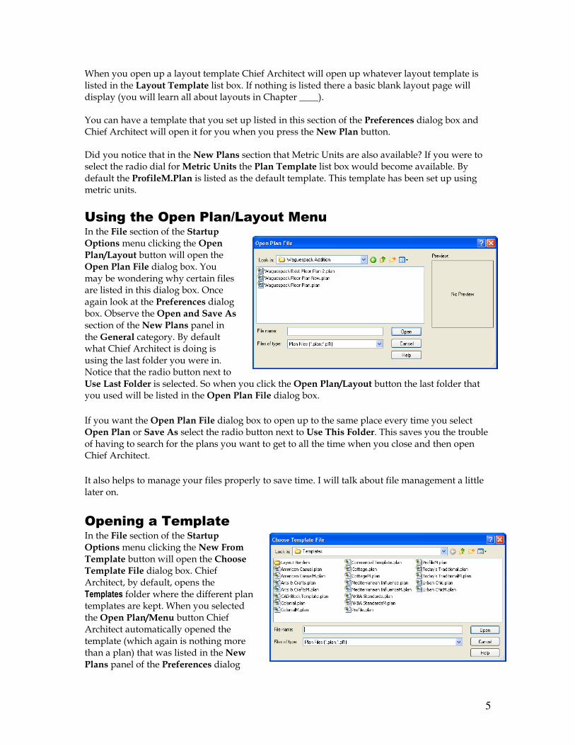
Using the Open Plan/Layout Menu In the File section of the Startup Options menu clicking the Open Plan/Layout button will open the Open Plan File dialog box. You may be wondering why certain files are listed in this dialog box. Once again look at the Preferences dialog box. Observe the Open and Save As section of the New Plans panel in the General category. By default what Chief Architect is doing is using the last folder you were in. Notice that the radio button next to Use Last Folder is selected. So when you click the Open Plan/Layout button the last folder that you used will be listed in the Open Plan File dialog box.
If you want the Open Plan File dialog box to open up to the same place every time you select Open Plan or Save As select the radio button next to Use This Folder. This saves you the trouble of having to search for the plans you want to get to all the time when you close and then open Chief Architect.
It also helps to manage your files properly to save time. I will talk about file management a little later on.
Opening a Template In the File section of the Startup Options menu clicking the New From Template button will open the Choose Template File dialog box. Chief Architect, by default, opens the Templates folder where the different plan templates are kept. When you selected the Open Plan/Menu button Chief Architect automatically opened the template (which again is nothing more than a plan) that was listed in the New Plans panel of the Preferences dialog
6
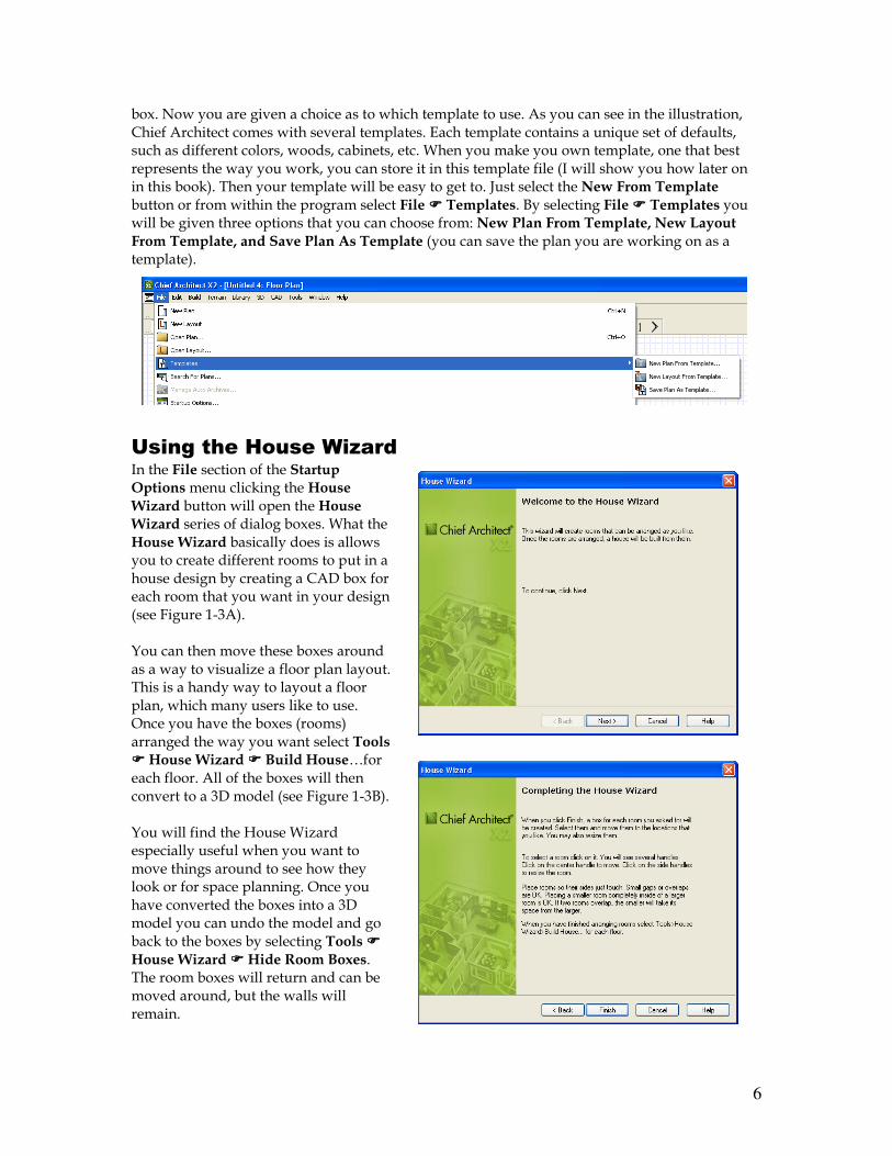
box. Now you are given a choice as to which template to use. As you can see in the illustration, Chief Architect comes with several templates. Each template contains a unique set of defaults, such as different colors, woods, cabinets, etc. When you make you own template, one that best represents the way you work, you can store it in this template file (I will show you how later on in this book). Then your template will be easy to get to. Just select the New From Template button or from within the program select File ���� Templates. By selecting File ���� Templates you will be given three options that you can choose from: New Plan From Template, New Layout From Template, and Save Plan As Template (you can save the plan you are working on as a template).
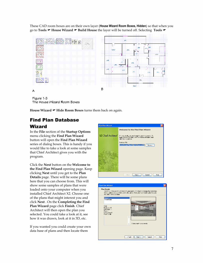
Using the House Wizard In the File section of the Startup Options menu clicking the House Wizard button will open the House Wizard series of dialog boxes. What the House Wizard basically does is allows you to create different rooms to put in a house design by creating a CAD box for each room that you want in your design (see Figure 1-3A). You can then move these boxes around as a way to visualize a floor plan layout. This is a handy way to layout a floor plan, which many users like to use. Once you have the boxes (rooms) arranged the way you want select Tools ���� House Wizard ���� Build House…for each floor. All of the boxes will then convert to a 3D model (see Figure 1-3B). You will find the House Wizard especially useful when you want to move things around to see how they look or for space planning. Once you have converted the boxes into a 3D model you can undo the model and go back to the boxes by selecting Tools ����
House Wizard ���� Hide Room Boxes. The room boxes will return and can be moved around, but the walls will remain.
7
These CAD room boxes are on their own layer (House Wizard Room Boxes, Hidden) so that when you go to Tools ���� House Wizard ���� Build House the layer will be turned off. Selecting Tools ����
House Wizard ���� Hide Room Boxes turns them back on again.
Find Plan Database
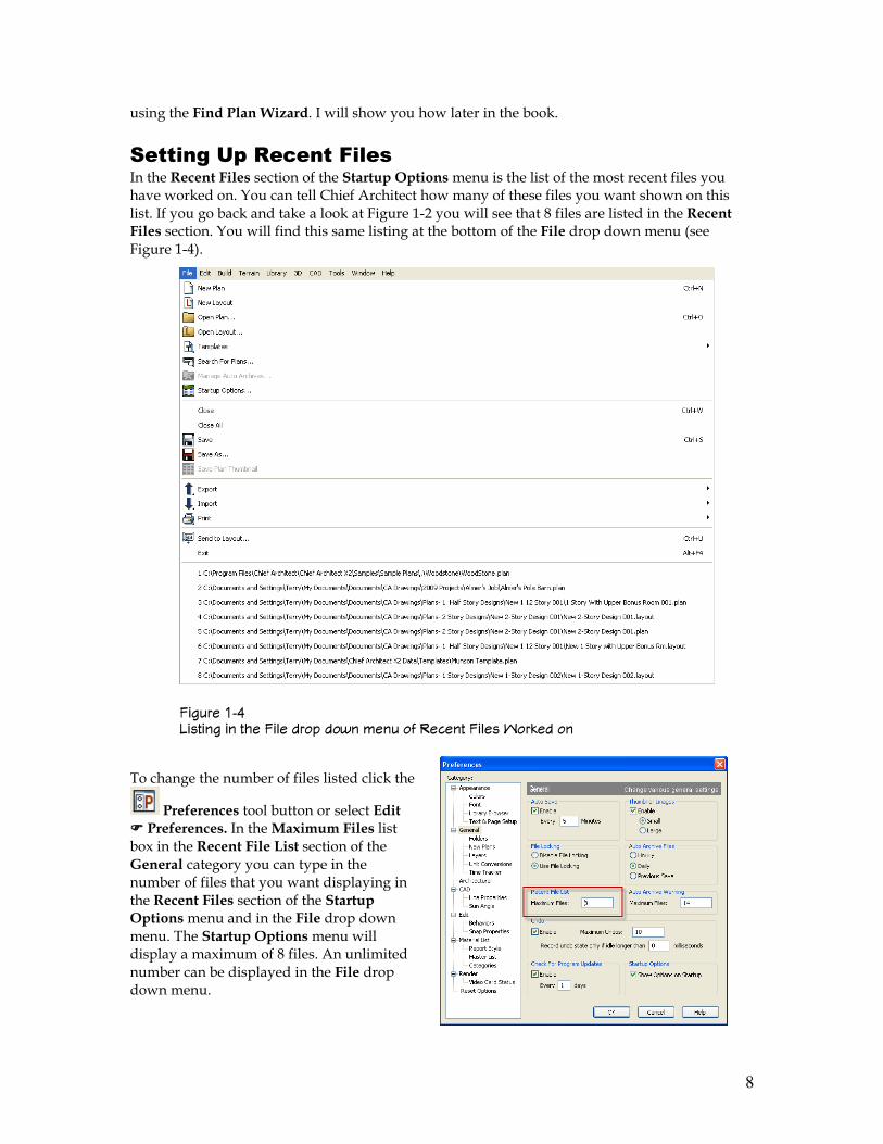
Wizard In the File section of the Startup Options menu clicking the Find Plan Wizard button will open the Find Plan Wizard
series of dialog boxes. This is handy if you would like to take a look at some samples that Chief Architect gives you with the program. Click the Next button on the Welcome to the Find Plan Wizard opening page. Keep clicking Next until you get to the Plan Details page. There will be some plans here that you can choose from. This will show some samples of plans that were loaded onto your computer when you installed Chief Architect X2. Choose one of the plans that might interest you and click Next . On the Completing the Find Plan Wizard page click Finish. Chief Architect will then open the plan you selected. You could take a look at it, see how it was drawn, look at it in 3D, etc. If you wanted you could create your own data base of plans and then locate them
�
������ �� �� ����� ������ ��! "�#��
"
8
using the Find Plan Wizard. I will show you how later in the book.
Setting Up Recent Files
In the Recent Files section of the Startup Options menu is the list of the most recent files you have worked on. You can tell Chief Architect how many of these files you want shown on this list. If you go back and take a look at Figure 1-2 you will see that 8 files are listed in the Recent Files section. You will find this same listing at the bottom of the File drop down menu (see Figure 1-4).
To change the number of files listed click the
Preferences tool button or select Edit ���� Preferences. In the Maximum Files list box in the Recent File List section of the General category you can type in the number of files that you want displaying in the Recent Files section of the Startup Options menu and in the File drop down menu. The Startup Options menu will display a maximum of 8 files. An unlimited number can be displayed in the File drop down menu.
������ �$ %������ �� ��� ��&� ���� ��'� !��� � ����� ��&�� ���(�� ��
9
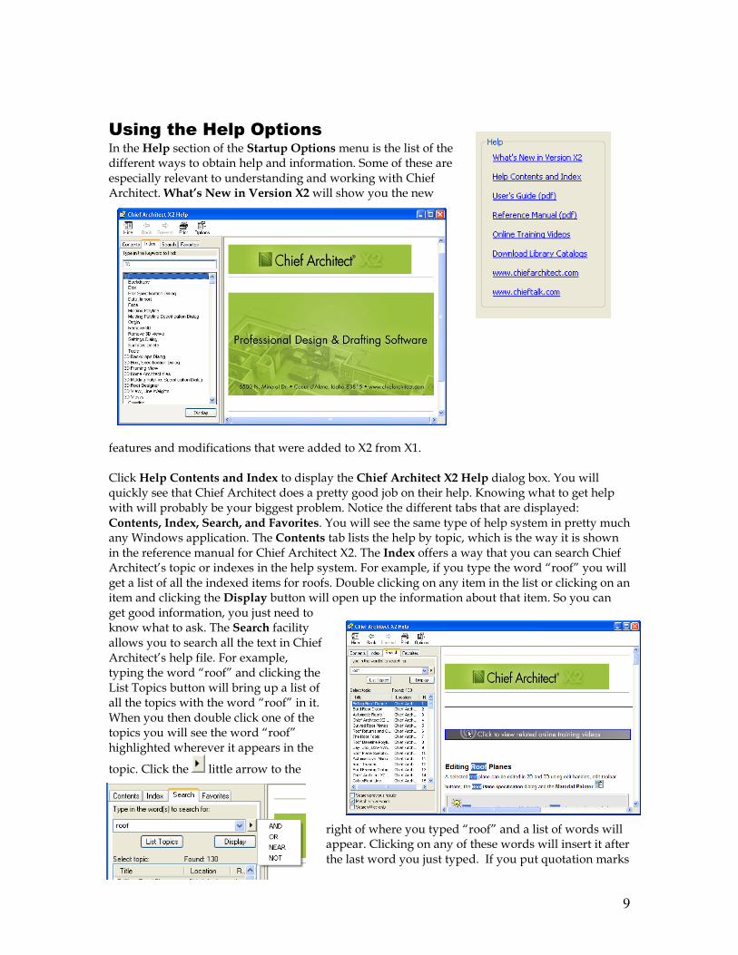
Using the Help Options
In the Help section of the Startup Options menu is the list of the different ways to obtain help and information. Some of these are especially relevant to understanding and working with Chief Architect. What’s New in Version X2 will show you the new
features and modifications that were added to X2 from X1. Click Help Contents and Index to display the Chief Architect X2 Help dialog box. You will quickly see that Chief Architect does a pretty good job on their help. Knowing what to get help with will probably be your biggest problem. Notice the different tabs that are displayed: Contents, Index, Search, and Favorites. You will see the same type of help system in pretty much any Windows application. The Contents tab lists the help by topic, which is the way it is shown in the reference manual for Chief Architect X2. The Index offers a way that you can search Chief Architect’s topic or indexes in the help system. For example, if you type the word “roof” you will get a list of all the indexed items for roofs. Double clicking on any item in the list or clicking on an item and clicking the Display button will open up the information about that item. So you can get good information, you just need to know what to ask. The Search facility allows you to search all the text in Chief Architect’s help file. For example, typing the word “roof” and clicking the List Topics button will bring up a list of all the topics with the word “roof” in it. When you then double click one of the topics you will see the word “roof” highlighted wherever it appears in the
topic. Click the little arrow to the
right of where you typed “roof” and a list of words will appear. Clicking on any of these words will insert it after the last word you just typed. If you put quotation marks
10
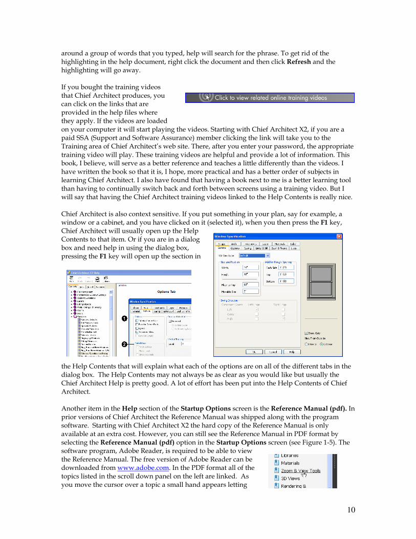
around a group of words that you typed, help will search for the phrase. To get rid of the highlighting in the help document, right click the document and then click Refresh and the highlighting will go away. If you bought the training videos that Chief Architect produces, you can click on the links that are provided in the help files where they apply. If the videos are loaded on your computer it will start playing the videos. Starting with Chief Architect X2, if you are a paid SSA (Support and Software Assurance) member clicking the link will take you to the Training area of Chief Architect’s web site. There, after you enter your password, the appropriate training video will play. These training videos are helpful and provide a lot of information. This book, I believe, will serve as a better reference and teaches a little differently than the videos. I have written the book so that it is, I hope, more practical and has a better order of subjects in learning Chief Architect. I also have found that having a book next to me is a better learning tool than having to continually switch back and forth between screens using a training video. But I will say that having the Chief Architect training videos linked to the Help Contents is really nice. Chief Architect is also context sensitive. If you put something in your plan, say for example, a window or a cabinet, and you have clicked on it (selected it), when you then press the F1 key, Chief Architect will usually open up the Help Contents to that item. Or if you are in a dialog box and need help in using the dialog box, pressing the F1 key will open up the section in
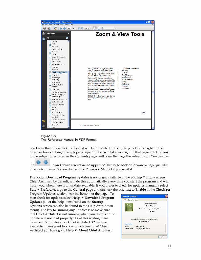
the Help Contents that will explain what each of the options are on all of the different tabs in the dialog box. The Help Contents may not always be as clear as you would like but usually the Chief Architect Help is pretty good. A lot of effort has been put into the Help Contents of Chief Architect. Another item in the Help section of the Startup Options screen is the Reference Manual (pdf). In prior versions of Chief Architect the Reference Manual was shipped along with the program software. Starting with Chief Architect X2 the hard copy of the Reference Manual is only available at an extra cost. However, you can still see the Reference Manual in PDF format by selecting the Reference Manual (pdf) option in the Startup Options screen (see Figure 1-5). The software program, Adobe Reader, is required to be able to view the Reference Manual. The free version of Adobe Reader can be downloaded from www.adobe.com. In the PDF format all of the topics listed in the scroll down panel on the left are linked. As you move the cursor over a topic a small hand appears letting
11
you know that if you click the topic it will be presented in the large panel to the right. In the index section, clicking on any topic’s page number will take you right to that page. Click on any of the subject titles listed in the Contents pages will open the page the subject is on. You can use
the up and down arrows in the upper tool bar to go back or forward a page, just like on a web browser. So you do have the Reference Manuel if you need it. The option Download Program Updates is no longer available in the Startup Options screen. Chief Architect, by default, will do this automatically every time you start the program and will notify you when there is an update available. If you prefer to check for updates manually select Edit ���� Preferences, go to the General page and uncheck the box next to Enable in the Check for Program Updates section near the bottom of the page. To then check for updates select Help ���� Download Program Updates (all of the help items listed on the Startup Options screen can also be found in the Help drop-down menu). The key to running any updates is to make sure that Chief Architect is not running when you do this or the update will not load properly. As of this writing there have been 5 updates since Chief Architect X2 became available. If you want to know which version of Chief Architect you have go to Help ���� About Chief Architect.
������ �) �� � ������ �����& �� *+� ���!��
12
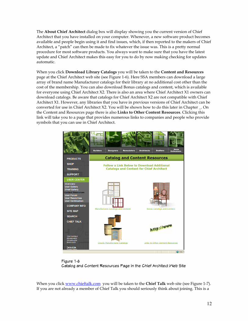
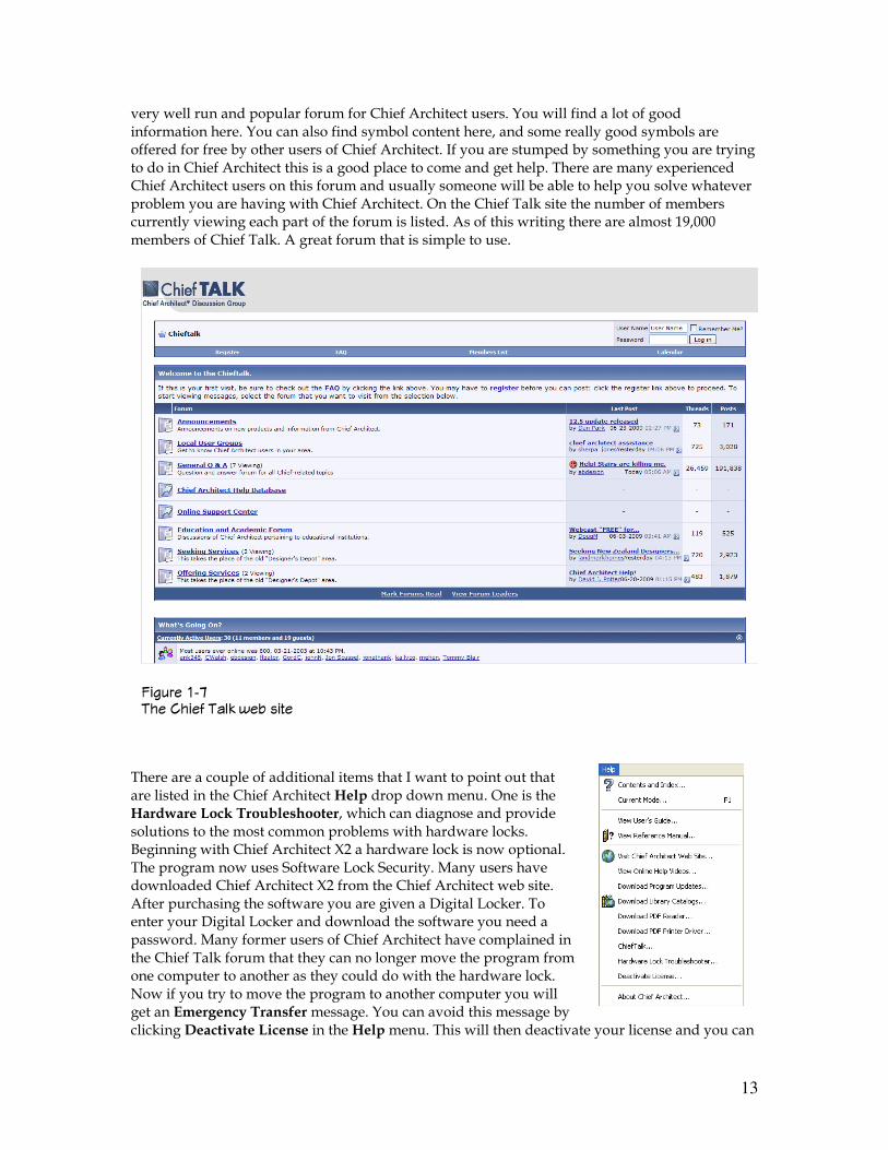
The About Chief Architect dialog box will display showing you the current version of Chief Architect that you have installed on your computer. Whenever, a new software product becomes available and people begin using it and find issues, which, if then reported to the makers of Chief Architect, a “patch” can then be made to fix whatever the issue was. This is a pretty normal procedure for most software products. You always want to make sure that you have the latest update and Chief Architect makes this easy for you to do by now making checking for updates automatic. When you click Download Library Catalogs you will be taken to the Content and Resources page at the Chief Architect web site (see Figure 1-6). Here SSA members can download a large array of brand name Manufacturer catalogs for their library at no additional cost other than the cost of the membership. You can also download Bonus catalogs and content, which is available for everyone using Chief Architect X2. There is also an area where Chief Architect X1 owners can download catalogs. Be aware that catalogs for Chief Architect X2 are not compatible with Chief Architect X1. However, any libraries that you have in previous versions of Chief Architect can be converted for use in Chief Architect X2. You will be shown how to do this later in Chapter _. On the Content and Resources page there is also Links to Other Content Resources. Clicking this link will take you to a page that provides numerous links to companies and people who provide symbols that you can use in Chief Architect. When you click www.chieftalk.com you will be taken to the Chief Talk web site (see Figure 1-7). If you are not already a member of Chief Talk you should seriously think about joining. This is a
������ �, ����&�� ��� ������� �������� *��� �� ��� ���� ��������� ��- ����
13
very well run and popular forum for Chief Architect users. You will find a lot of good information here. You can also find symbol content here, and some really good symbols are offered for free by other users of Chief Architect. If you are stumped by something you are trying to do in Chief Architect this is a good place to come and get help. There are many experienced Chief Architect users on this forum and usually someone will be able to help you solve whatever problem you are having with Chief Architect. On the Chief Talk site the number of members currently viewing each part of the forum is listed. As of this writing there are almost 19,000 members of Chief Talk. A great forum that is simple to use.
There are a couple of additional items that I want to point out that are listed in the Chief Architect Help drop down menu. One is the Hardware Lock Troubleshooter, which can diagnose and provide solutions to the most common problems with hardware locks. Beginning with Chief Architect X2 a hardware lock is now optional. The program now uses Software Lock Security. Many users have downloaded Chief Architect X2 from the Chief Architect web site. After purchasing the software you are given a Digital Locker. To enter your Digital Locker and download the software you need a password. Many former users of Chief Architect have complained in the Chief Talk forum that they can no longer move the program from one computer to another as they could do with the hardware lock. Now if you try to move the program to another computer you will get an Emergency Transfer message. You can avoid this message by clicking Deactivate License in the Help menu. This will then deactivate your license and you can
������ �. �� ���� �&( '�- ����
14
then move the program to another computer and reactivate the license on that computer. A license of Chief Architect can only be active on one computer at any given time. You are limited as to how many emergency transfers that you can do so it is important to avoid doing an emergency transfer unless it is actually an emergency such as a hard drive that quits to operate.
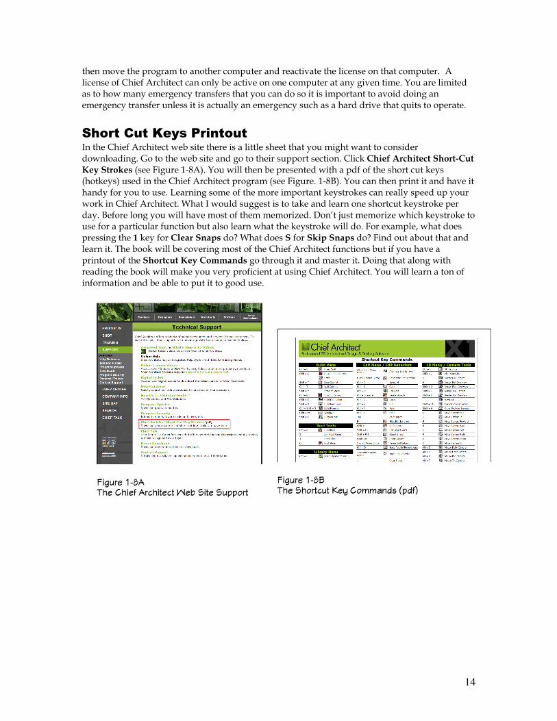
Short Cut Keys Printout In the Chief Architect web site there is a little sheet that you might want to consider downloading. Go to the web site and go to their support section. Click Chief Architect Short-Cut Key Strokes (see Figure 1-8A). You will then be presented with a pdf of the short cut keys (hotkeys) used in the Chief Architect program (see Figure. 1-8B). You can then print it and have it handy for you to use. Learning some of the more important keystrokes can really speed up your work in Chief Architect. What I would suggest is to take and learn one shortcut keystroke per day. Before long you will have most of them memorized. Don’t just memorize which keystroke to use for a particular function but also learn what the keystroke will do. For example, what does pressing the 1 key for Clear Snaps do? What does S for Skip Snaps do? Find out about that and learn it. The book will be covering most of the Chief Architect functions but if you have a printout of the Shortcut Key Commands go through it and master it. Doing that along with reading the book will make you very proficient at using Chief Architect. You will learn a ton of information and be able to put it to good use.
������ �/� �� ���� ��������� ��- ���� �������
������ �/" �� �������� 0�1 ��!!���� 2�� 3
15
Chief Architect X2 Toolbars and Menus
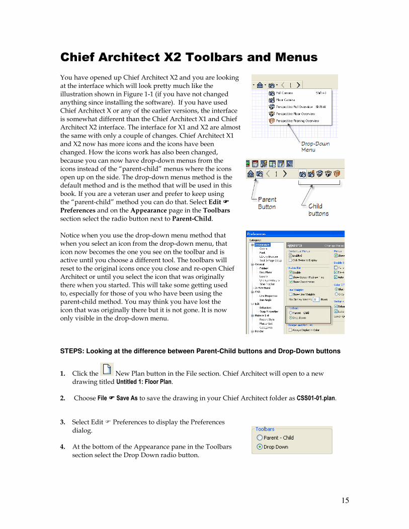
You have opened up Chief Architect X2 and you are looking at the interface which will look pretty much like the illustration shown in Figure 1-1 (if you have not changed anything since installing the software). If you have used Chief Architect X or any of the earlier versions, the interface is somewhat different than the Chief Architect X1 and Chief Architect X2 interface. The interface for X1 and X2 are almost the same with only a couple of changes. Chief Architect X1 and X2 now has more icons and the icons have been changed. How the icons work has also been changed, because you can now have drop-down menus from the icons instead of the “parent-child” menus where the icons open up on the side. The drop-down menus method is the default method and is the method that will be used in this book. If you are a veteran user and prefer to keep using the “parent-child” method you can do that. Select Edit ����
Preferences and on the Appearance page in the Toolbars section select the radio button next to Parent-Child. Notice when you use the drop-down menu method that when you select an icon from the drop-down menu, that icon now becomes the one you see on the toolbar and is active until you choose a different tool. The toolbars will reset to the original icons once you close and re-open Chief Architect or until you select the icon that was originally there when you started. This will take some getting used to, especially for those of you who have been using the parent-child method. You may think you have lost the icon that was originally there but it is not gone. It is now only visible in the drop-down menu. STEPS: Looking at the difference between Parent-Child buttons and Drop-Down buttons
1. Click the New Plan button in the File section. Chief Architect will open to a new drawing titled Untitled 1: Floor Plan.
2. Choose File ���� Save As to save the drawing in your Chief Architect folder as CSS01-01.plan.
3. Select Edit � Preferences to display the Preferences dialog.
4. At the bottom of the Appearance pane in the Toolbars section select the Drop Down radio button.
16
5. Click OK.
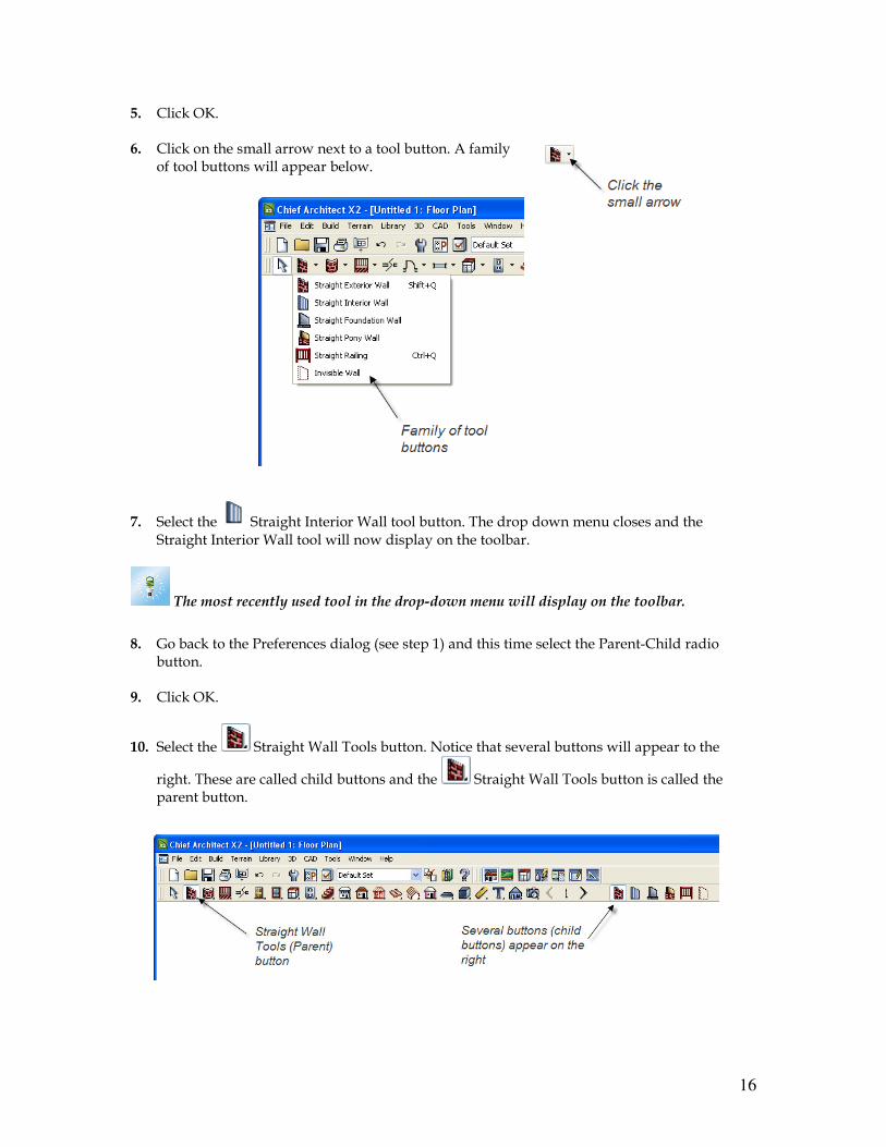
6. Click on the small arrow next to a tool button. A family of tool buttons will appear below.
7. Select the Straight Interior Wall tool button. The drop down menu closes and the Straight Interior Wall tool will now display on the toolbar.
The most recently used tool in the drop-down menu will display on the toolbar.
8. Go back to the Preferences dialog (see step 1) and this time select the Parent-Child radio
button.
9. Click OK.
10. Select the Straight Wall Tools button. Notice that several buttons will appear to the
right. These are called child buttons and the Straight Wall Tools button is called the parent button.
17
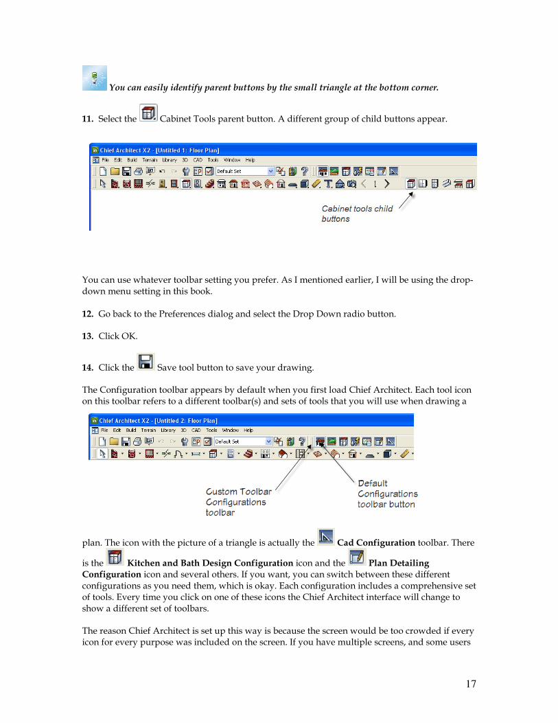
You can easily identify parent buttons by the small triangle at the bottom corner.
11. Select the Cabinet Tools parent button. A different group of child buttons appear.
You can use whatever toolbar setting you prefer. As I mentioned earlier, I will be using the drop-down menu setting in this book. 12. Go back to the Preferences dialog and select the Drop Down radio button.
13. Click OK.
14. Click the Save tool button to save your drawing.
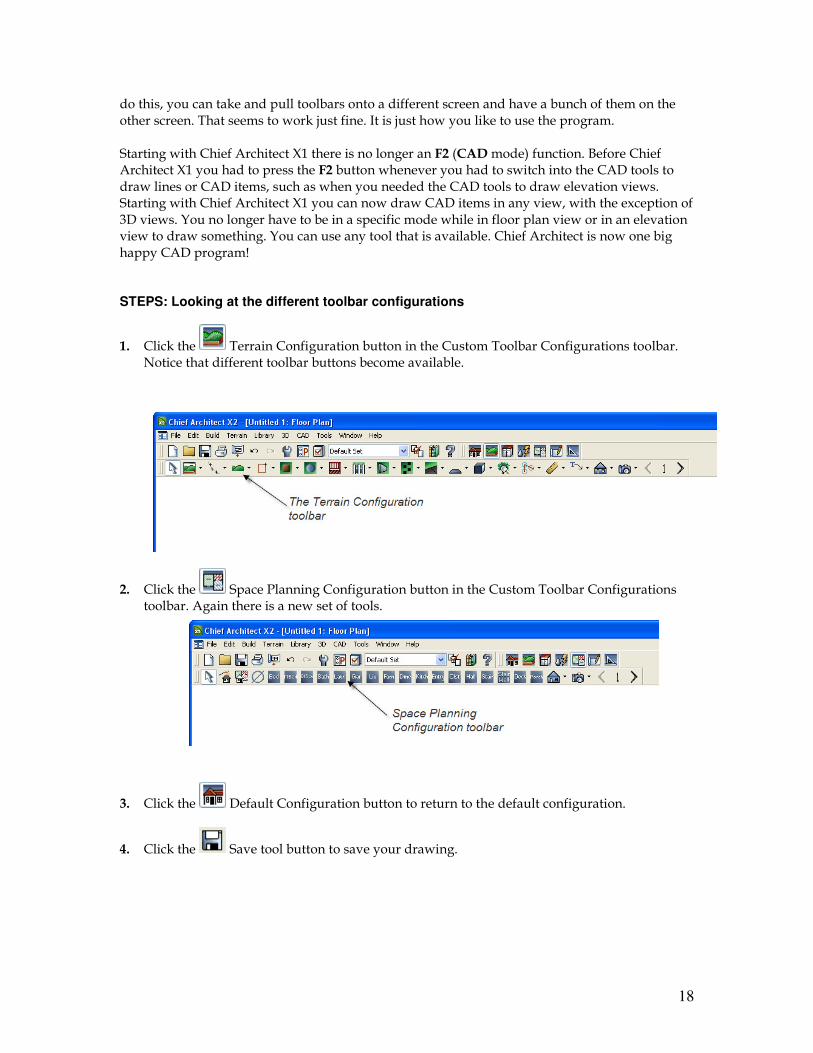
The Configuration toolbar appears by default when you first load Chief Architect. Each tool icon on this toolbar refers to a different toolbar(s) and sets of tools that you will use when drawing a
plan. The icon with the picture of a triangle is actually the Cad Configuration toolbar. There
is the Kitchen and Bath Design Configuration icon and the Plan Detailing Configuration icon and several others. If you want, you can switch between these different configurations as you need them, which is okay. Each configuration includes a comprehensive set of tools. Every time you click on one of these icons the Chief Architect interface will change to show a different set of toolbars.
The reason Chief Architect is set up this way is because the screen would be too crowded if every icon for every purpose was included on the screen. If you have multiple screens, and some users
18
do this, you can take and pull toolbars onto a different screen and have a bunch of them on the other screen. That seems to work just fine. It is just how you like to use the program. Starting with Chief Architect X1 there is no longer an F2 (CAD mode) function. Before Chief Architect X1 you had to press the F2 button whenever you had to switch into the CAD tools to draw lines or CAD items, such as when you needed the CAD tools to draw elevation views. Starting with Chief Architect X1 you can now draw CAD items in any view, with the exception of 3D views. You no longer have to be in a specific mode while in floor plan view or in an elevation view to draw something. You can use any tool that is available. Chief Architect is now one big happy CAD program! STEPS: Looking at the different toolbar configurations
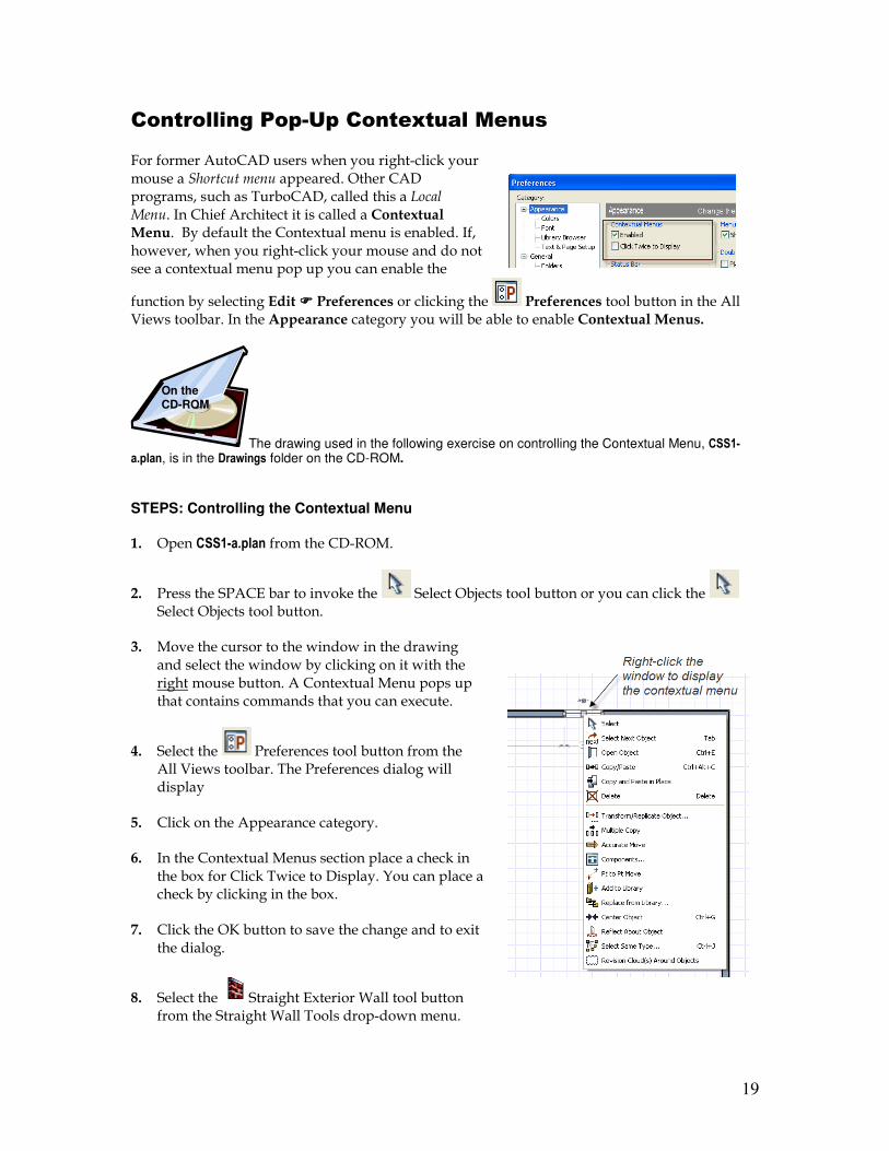
1. Click the Terrain Configuration button in the Custom Toolbar Configurations toolbar. Notice that different toolbar buttons become available.
2. Click the Space Planning Configuration button in the Custom Toolbar Configurations toolbar. Again there is a new set of tools.
3. Click the Default Configuration button to return to the default configuration.
4. Click the Save tool button to save your drawing.
19
Controlling Pop-Up Contextual Menus
For former AutoCAD users when you right-click your mouse a Shortcut menu appeared. Other CAD programs, such as TurboCAD, called this a Local Menu. In Chief Architect it is called a Contextual Menu. By default the Contextual menu is enabled. If, however, when you right-click your mouse and do not see a contextual menu pop up you can enable the
function by selecting Edit ���� Preferences or clicking the Preferences tool button in the All Views toolbar. In the Appearance category you will be able to enable Contextual Menus.
The drawing used in the following exercise on controlling the Contextual Menu, CSS1-a.plan, is in the Drawings folder on the CD-ROM.
STEPS: Controlling the Contextual Menu
1. Open CSS1-a.plan from the CD-ROM.
2. Press the SPACE bar to invoke the Select Objects tool button or you can click the Select Objects tool button.
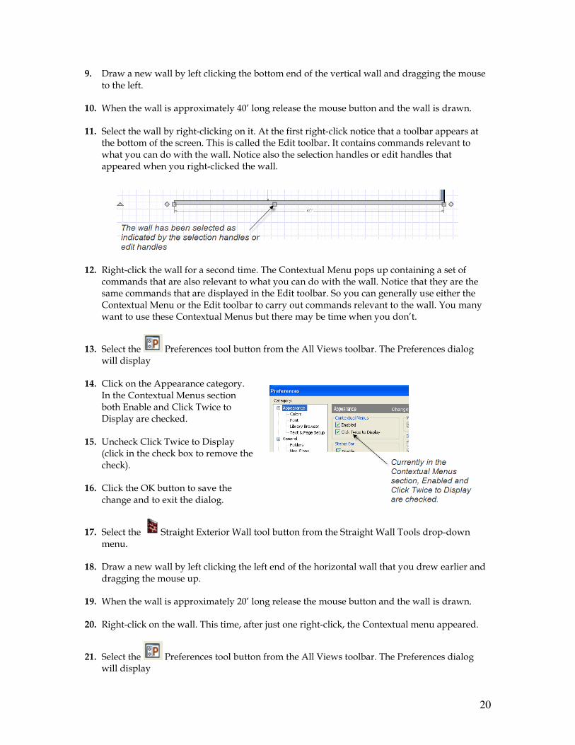
3. Move the cursor to the window in the drawing and select the window by clicking on it with the right mouse button. A Contextual Menu pops up that contains commands that you can execute.
4. Select the Preferences tool button from the All Views toolbar. The Preferences dialog will display
5. Click on the Appearance category.
6. In the Contextual Menus section place a check in the box for Click Twice to Display. You can place a check by clicking in the box.
7. Click the OK button to save the change and to exit the dialog.
8. Select the Straight Exterior Wall tool button from the Straight Wall Tools drop-down menu.
On the CD-ROM
20
9. Draw a new wall by left clicking the bottom end of the vertical wall and dragging the mouse to the left.
10. When the wall is approximately 40’ long release the mouse button and the wall is drawn.
11. Select the wall by right-clicking on it. At the first right-click notice that a toolbar appears at the bottom of the screen. This is called the Edit toolbar. It contains commands relevant to what you can do with the wall. Notice also the selection handles or edit handles that appeared when you right-clicked the wall.
12. Right-click the wall for a second time. The Contextual Menu pops up containing a set of commands that are also relevant to what you can do with the wall. Notice that they are the same commands that are displayed in the Edit toolbar. So you can generally use either the Contextual Menu or the Edit toolbar to carry out commands relevant to the wall. You many want to use these Contextual Menus but there may be time when you don’t.
13. Select the Preferences tool button from the All Views toolbar. The Preferences dialog will display
14. Click on the Appearance category. In the Contextual Menus section both Enable and Click Twice to Display are checked.
15. Uncheck Click Twice to Display (click in the check box to remove the check).
16. Click the OK button to save the change and to exit the dialog.
17. Select the Straight Exterior Wall tool button from the Straight Wall Tools drop-down menu.
18. Draw a new wall by left clicking the left end of the horizontal wall that you drew earlier and dragging the mouse up.
19. When the wall is approximately 20’ long release the mouse button and the wall is drawn.
20. Right-click on the wall. This time, after just one right-click, the Contextual menu appeared.
21. Select the Preferences tool button from the All Views toolbar. The Preferences dialog will display
21
22. Click on the Appearance category.
23. In the Contextual Menus section, uncheck Enabled.
24. Click the OK button to save the change and to exit the dialog.
25. Right click the vertical wall you just drew. Now the Contextual Menu does not appear. The commands, however, are still available in the Edit toolbar, which displays when you either right-click or left-click to select the wall or any object.
26. Go back to the Preferences dialog and in the Contextual Menus section re-check Enabled.
27. Close the drawing. Select No when asked if you want to save the modifications.
So whenever you want to modify the display of Contextual Menus go to Edit ���� Preferences or
select the Preferences tool button from the All Views toolbar. Then go to the Appearance category and the options you choose will remain selected every time you use Chief Architect until you change them again.
Extended Tool Configuration
The following exercise will display the Extended Tool Configuration setup on your display of the Chief Architect X2 interface. I believe that this configuration set-up will save you time when working with Chief Architect X2. I will be using this configuration for the rest of the book. STEPS: Looking at the Extended Tool Configuration 1. Open your CSS01-01.plan if it is not already open. If you did not create this drawing you can
use CSS1-b.plan that is on the CD.
2. Move the cursor over any tool button in any of the
toolbars and right-click.
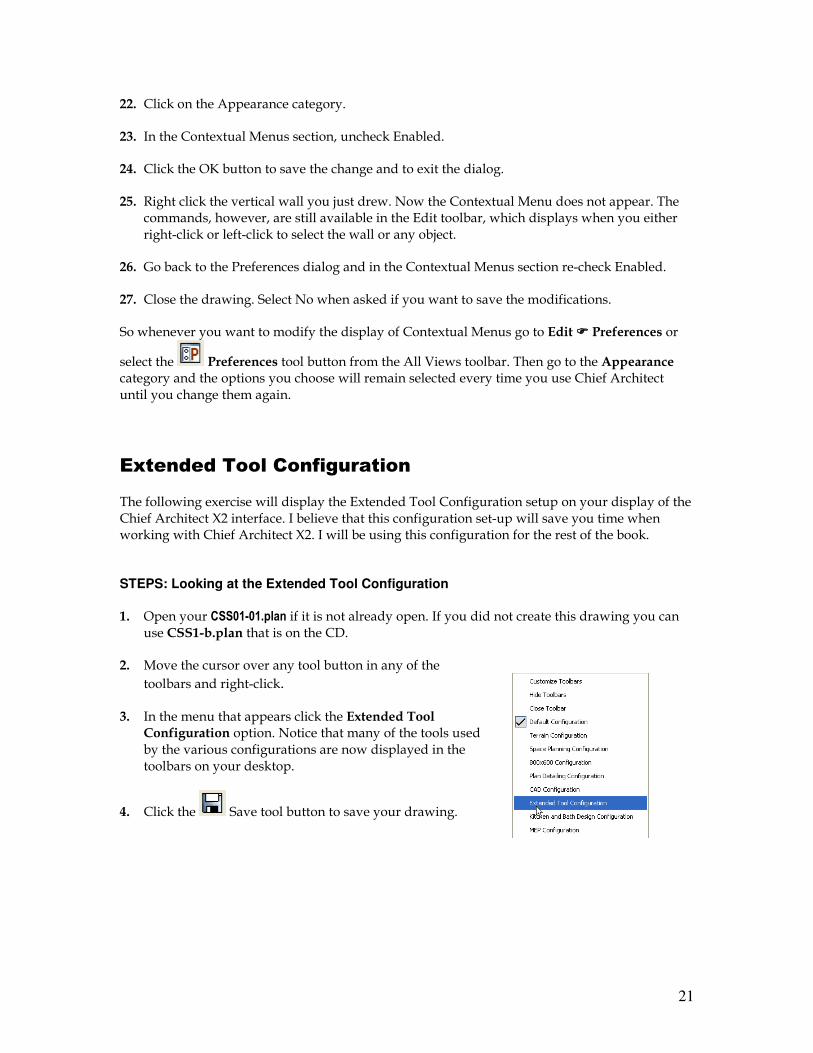
3. In the menu that appears click the Extended Tool Configuration option. Notice that many of the tools used by the various configurations are now displayed in the toolbars on your desktop.
4. Click the Save tool button to save your drawing.
22
������ �4 �� ������������& ��&� ���&-�� �� ��' &������
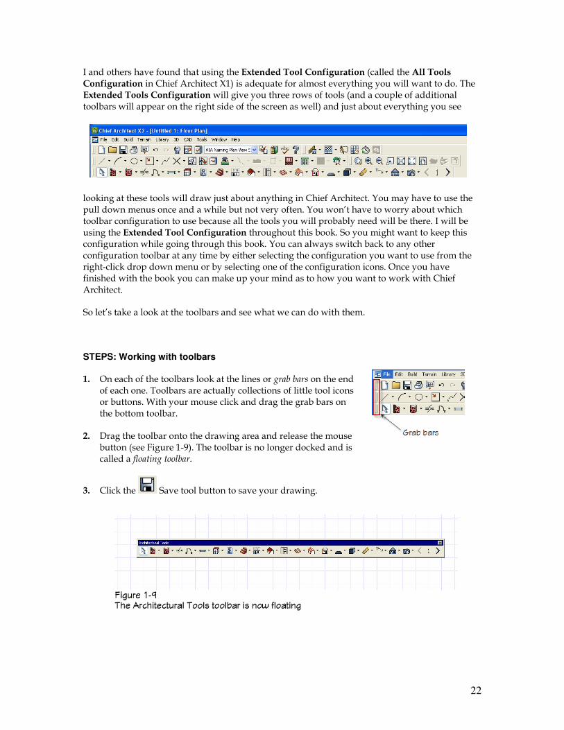
I and others have found that using the Extended Tool Configuration (called the All Tools Configuration in Chief Architect X1) is adequate for almost everything you will want to do. The Extended Tools Configuration will give you three rows of tools (and a couple of additional toolbars will appear on the right side of the screen as well) and just about everything you see
looking at these tools will draw just about anything in Chief Architect. You may have to use the pull down menus once and a while but not very often. You won’t have to worry about which toolbar configuration to use because all the tools you will probably need will be there. I will be using the Extended Tool Configuration throughout this book. So you might want to keep this configuration while going through this book. You can always switch back to any other configuration toolbar at any time by either selecting the configuration you want to use from the right-click drop down menu or by selecting one of the configuration icons. Once you have finished with the book you can make up your mind as to how you want to work with Chief Architect.
So let’s take a look at the toolbars and see what we can do with them.
STEPS: Working with toolbars
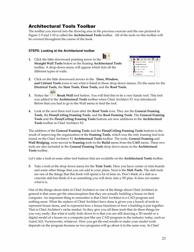
1. On each of the toolbars look at the lines or grab bars on the end of each one. Toolbars are actually collections of little tool icons or buttons. With your mouse click and drag the grab bars on the bottom toolbar.
2. Drag the toolbar onto the drawing area and release the mouse button (see Figure 1-9). The toolbar is no longer docked and is called a floating toolbar.
3. Click the Save tool button to save your drawing.
23
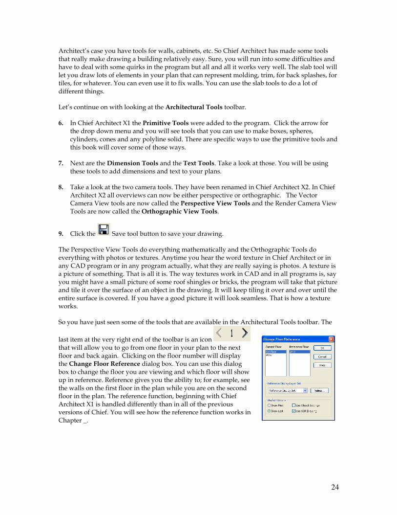
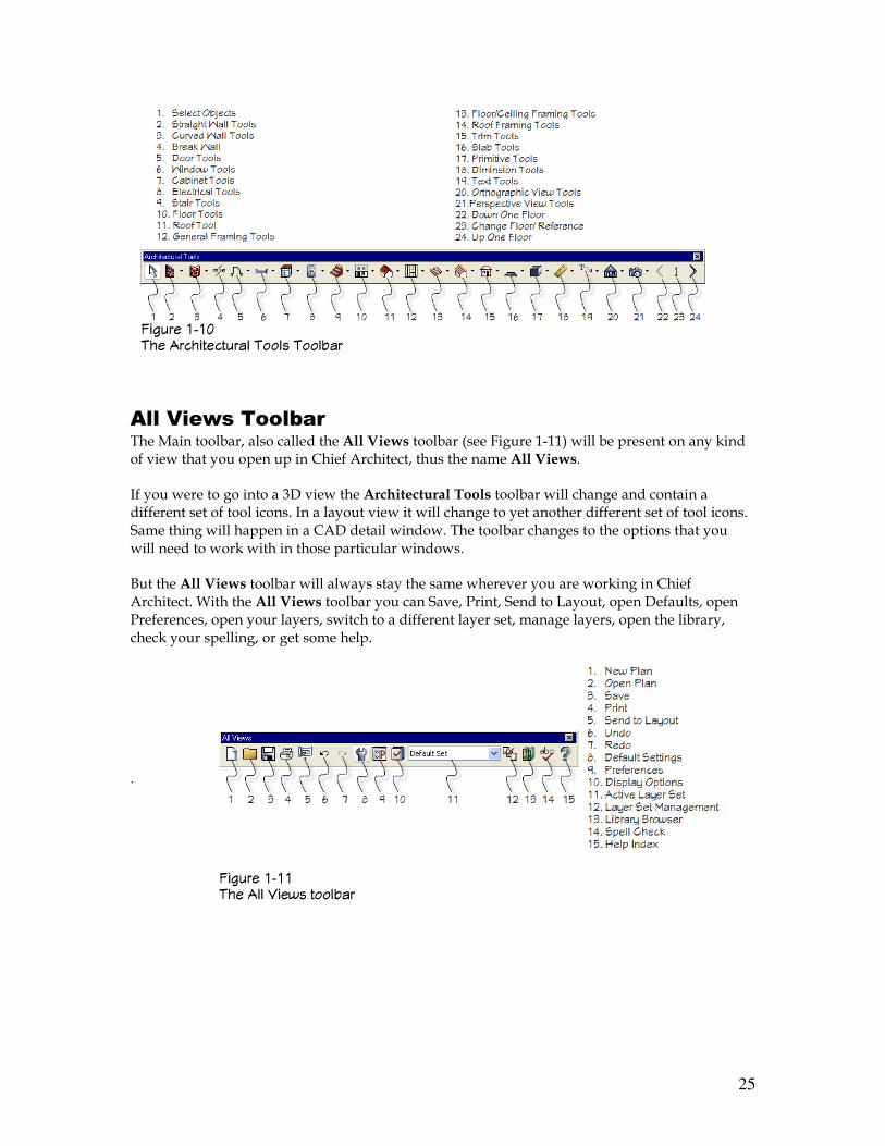
Architectural Tools Toolbar The toolbar you moved into the drawing area in the previous exercise and the one pictured in Figure 1-9 and 1-10 is called the Architectural Tools toolbar. All of the tools on this toolbar will be covered throughout the course of the book. STEPS: Looking at the Architectural toolbar
1. Click the little downward pointing arrow in the Straight Wall Tools button in the floating Architectural Tools toolbar. A drop-down menu will appear which lists all the different types of walls.
2. Click on the little downward arrows in the Door, Window,
and Cabinet Tools icons to see what is listed in those drop-down menus. Do the same for the Electrical Tools, the Stair Tools, Floor Tools, and the Roof Tools.
3. Notice the Break Wall tool button. You will find this to be a very handy tool. This tool was added to the Architectural Tools toolbar when Chief Architect X1 was introduced. Before that you had to go to the Wall menu to find the tool.
4. Look at the next three tool icons after the Roof Tools icon. They are the General Framing Tools, the Floor/Ceiling Framing Tools, and the Roof Framing Tools. The General Framing Tools and the Floor/Ceiling Framing Tools buttons are new additions to the Architectural Tools toolbar in Chief Architect X2.
The addition of the General Framing Tools and the Floor/Ceiling Framing Tools buttons is the result of improving the organization of the Framing Tools, which was the only framing tool icon found on the Chief Architect X1 Architectural Tools toolbar. The tools, General Framing and Wall Bridging, were moved to Framing tools in the Build menu from the CAD menu. These two tools are also included in the General Framing Tools drop down menu in the Architectural Tools toolbar. Let’s take a look at some other tool buttons that are available on the Architectural Tools toolbar.
5. Take a look at the drop down menu for the Trim Tools. Here you have corner or trim boards and some other things that you can add to your plans. Next is the Slab Tools. The slab tools are one of the things that this book will spend a lot of time on. Don’t think of a slab as a concrete slab but think of it as something you will draw into a 3D plan. It does not matter what it is.
One of the things about slabs in Chief Architect or one of the things about Chief Architect in general is that users get the misconception that they are actually building a house on their computer. An important thing to remember is that Chief Architect is a CAD program and nothing more. What the makers of Chief Architect have done is given you a bunch of tools to represent house items, and to represent how a house functions or how a building is put together. That is Chief Architect’s niche market. So they give you all these tools that do these things for you very easily. But what it really boils down to is that you are still drawing a 3D model or a digital model of a house on a computer just like any CAD program in the industry today, such as AutoCAD, Vectorworks, whatever. How you get the end results to make your model work depends on the program because no two programs will go about it in the same way. In Chief
24
Architect’s case you have tools for walls, cabinets, etc. So Chief Architect has made some tools that really make drawing a building relatively easy. Sure, you will run into some difficulties and have to deal with some quirks in the program but all and all it works very well. The slab tool will let you draw lots of elements in your plan that can represent molding, trim, for back splashes, for tiles, for whatever. You can even use it to fix walls. You can use the slab tools to do a lot of different things.
Let’s continue on with looking at the Architectural Tools toolbar.
6. In Chief Architect X1 the Primitive Tools were added to the program. Click the arrow for the drop down menu and you will see tools that you can use to make boxes, spheres, cylinders, cones and any polyline solid. There are specific ways to use the primitive tools and this book will cover some of those ways.
7. Next are the Dimension Tools and the Text Tools. Take a look at those. You will be using these tools to add dimensions and text to your plans.
8. Take a look at the two camera tools. They have been renamed in Chief Architect X2. In Chief Architect X2 all overviews can now be either perspective or orthographic. The Vector Camera View tools are now called the Perspective View Tools and the Render Camera View Tools are now called the Orthographic View Tools.
9. Click the Save tool button to save your drawing.
The Perspective View Tools do everything mathematically and the Orthographic Tools do everything with photos or textures. Anytime you hear the word texture in Chief Architect or in any CAD program or in any program actually, what they are really saying is photos. A texture is a picture of something. That is all it is. The way textures work in CAD and in all programs is, say you might have a small picture of some roof shingles or bricks, the program will take that picture and tile it over the surface of an object in the drawing. It will keep tiling it over and over until the entire surface is covered. If you have a good picture it will look seamless. That is how a texture works.
So you have just seen some of the tools that are available in the Architectural Tools toolbar. The
last item at the very right end of the toolbar is an icon that will allow you to go from one floor in your plan to the next floor and back again. Clicking on the floor number will display the Change Floor Reference dialog box. You can use this dialog box to change the floor you are viewing and which floor will show up in reference. Reference gives you the ability to; for example, see the walls on the first floor in the plan while you are on the second floor in the plan. The reference function, beginning with Chief Architect X1 is handled differently than in all of the previous versions of Chief. You will see how the reference function works in Chapter _.
25
All Views Toolbar The Main toolbar, also called the All Views toolbar (see Figure 1-11) will be present on any kind of view that you open up in Chief Architect, thus the name All Views.
If you were to go into a 3D view the Architectural Tools toolbar will change and contain a different set of tool icons. In a layout view it will change to yet another different set of tool icons. Same thing will happen in a CAD detail window. The toolbar changes to the options that you will need to work with in those particular windows.
But the All Views toolbar will always stay the same wherever you are working in Chief Architect. With the All Views toolbar you can Save, Print, Send to Layout, open Defaults, open Preferences, open your layers, switch to a different layer set, manage layers, open the library, check your spelling, or get some help.
.
������ ��� �� �&& 5��'� ���&-��
������ ��6 �� ������������& ��&� ��&-��
26
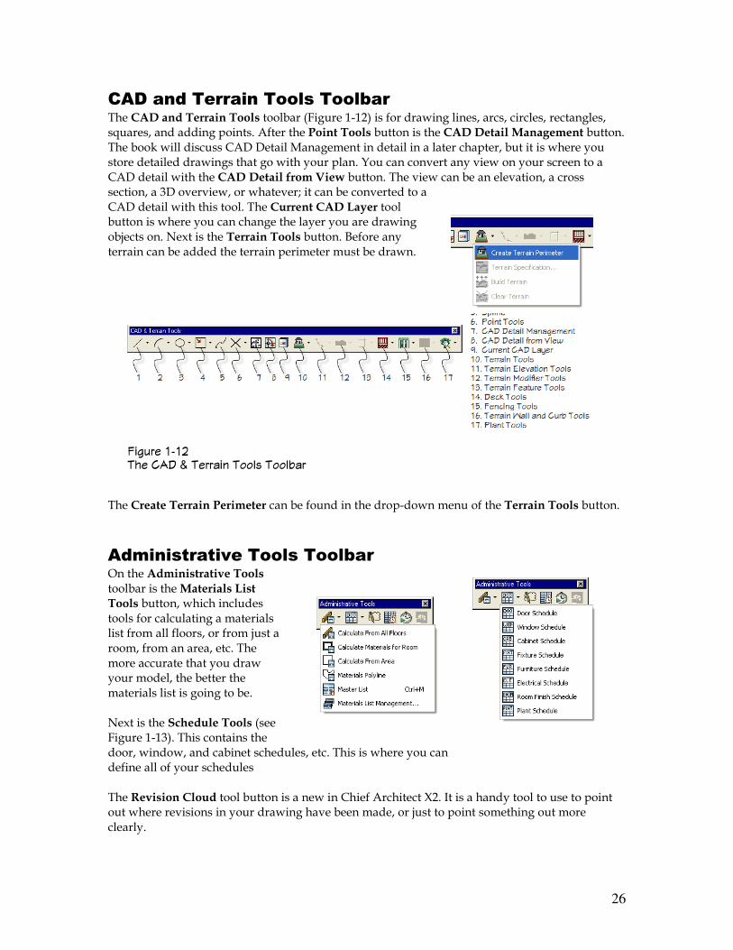
CAD and Terrain Tools Toolbar The CAD and Terrain Tools toolbar (Figure 1-12) is for drawing lines, arcs, circles, rectangles, squares, and adding points. After the Point Tools button is the CAD Detail Management button. The book will discuss CAD Detail Management in detail in a later chapter, but it is where you store detailed drawings that go with your plan. You can convert any view on your screen to a CAD detail with the CAD Detail from View button. The view can be an elevation, a cross section, a 3D overview, or whatever; it can be converted to a CAD detail with this tool. The Current CAD Layer tool button is where you can change the layer you are drawing objects on. Next is the Terrain Tools button. Before any terrain can be added the terrain perimeter must be drawn.
The Create Terrain Perimeter can be found in the drop-down menu of the Terrain Tools button.
Administrative Tools Toolbar On the Administrative Tools toolbar is the Materials List Tools button, which includes tools for calculating a materials list from all floors, or from just a room, from an area, etc. The more accurate that you draw your model, the better the materials list is going to be. Next is the Schedule Tools (see Figure 1-13). This contains the door, window, and cabinet schedules, etc. This is where you can define all of your schedules The Revision Cloud tool button is a new in Chief Architect X2. It is a handy tool to use to point out where revisions in your drawing have been made, or just to point something out more clearly.
������ ��� �� ��+ 7 ������ ��&� ��&-��
27
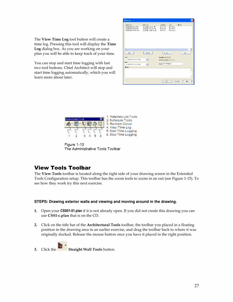
The View Time Log tool button will create a time log. Pressing this tool will display the Time Log dialog box. As you are working on your plan you will be able to keep track of your time. You can stop and start time logging with last two tool buttons. Chief Architect will stop and start time logging automatically, which you will learn more about later.
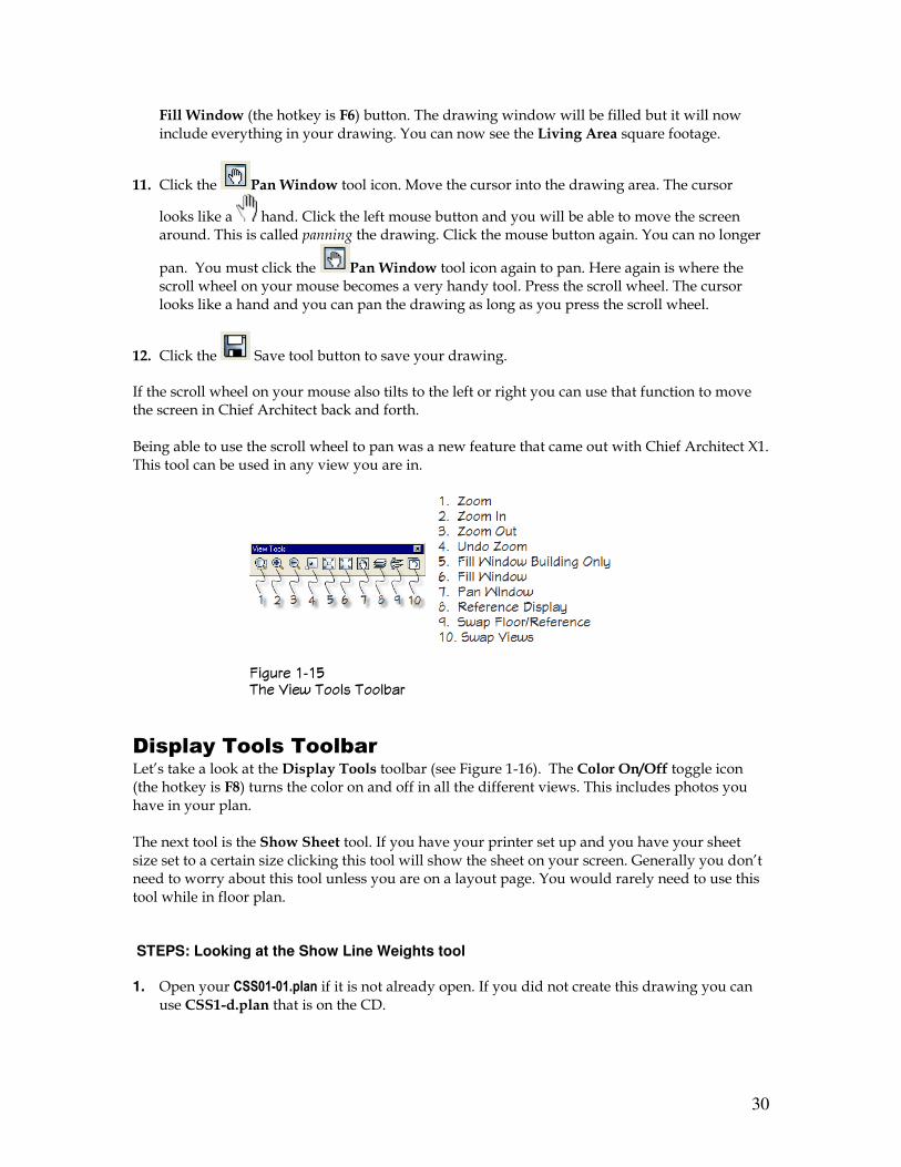
View Tools Toolbar The View Tools toolbar is located along the right side of your drawing screen in the Extended Tools Configuration setup. This toolbar has the zoom tools to zoom in an out (see Figure 1-15). To see how they work try this next exercise.
STEPS: Drawing exterior walls and viewing and moving around in the drawing.
1. Open your CSS01-01.plan if it is not already open. If you did not create this drawing you can use CSS1-c.plan that is on the CD.
2. Click on the title bar of the Architectural Tools toolbar, the toolbar you placed in a floating position in the drawing area in an earlier exercise, and drag the toolbar back to where it was originally docked. Release the mouse button once you have it placed in the right position.
3. Click the Straight Wall Tools button.
������ ��� �� ��!���������8� ��&� ��&-��
28
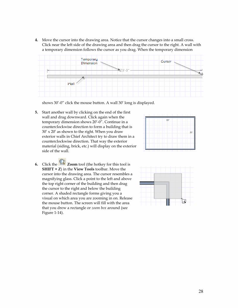
4. Move the cursor into the drawing area. Notice that the cursor changes into a small cross. Click near the left side of the drawing area and then drag the cursor to the right. A wall with a temporary dimension follows the cursor as you drag. When the temporary dimension
shows 30’-0” click the mouse button. A wall 30’ long is displayed.
5. Start another wall by clicking on the end of the first wall and drag downward. Click again when the temporary dimension shows 20’-0”. Continue in a counterclockwise direction to form a building that is 30’ x 20’ as shown to the right. When you draw exterior walls in Chief Architect try to draw them in a counterclockwise direction. That way the exterior material (siding, brick, etc.) will display on the exterior side of the wall.
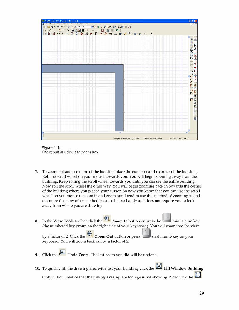
6. Click the Zoom tool (the hotkey for this tool is SHIFT + Z) in the View Tools toolbar. Move the cursor into the drawing area. The cursor resembles a magnifying glass. Click a point to the left and above the top right corner of the building and then drag the cursor to the right and below the building corner. A shaded rectangle forms giving you a visual on which area you are zooming in on. Release the mouse button. The screen will fill with the area that you drew a rectangle or zoom box around (see Figure 1-14).
29
7. To zoom out and see more of the building place the cursor near the corner of the building. Roll the scroll wheel on your mouse towards you. You will begin zooming away from the building. Keep rolling the scroll wheel towards you until you can see the entire building. Now roll the scroll wheel the other way. You will begin zooming back in towards the corner of the building where you placed your cursor. So now you know that you can use the scroll wheel on you mouse to zoom in and zoom out. I tend to use this method of zooming in and out more than any other method because it is so handy and does not require you to look away from where you are drawing.
8. In the View Tools toolbar click the Zoom In button or press the minus num key (the numbered key group on the right side of your keyboard). You will zoom into the view
by a factor of 2. Click the Zoom Out button or press slash numb key on your keyboard. You will zoom back out by a factor of 2.
9. Click the Undo Zoom. The last zoom you did will be undone.
10. To quickly fill the drawing area with just your building, click the Fill Window Building
Only button. Notice that the Living Area square footage is not showing. Now click the
������ ��$ �� ����&� � ����� ��� ���! -�#
30
Fill Window (the hotkey is F6) button. The drawing window will be filled but it will now include everything in your drawing. You can now see the Living Area square footage.
11. Click the Pan Window tool icon. Move the cursor into the drawing area. The cursor
looks like a hand. Click the left mouse button and you will be able to move the screen around. This is called panning the drawing. Click the mouse button again. You can no longer
pan. You must click the Pan Window tool icon again to pan. Here again is where the scroll wheel on your mouse becomes a very handy tool. Press the scroll wheel. The cursor looks like a hand and you can pan the drawing as long as you press the scroll wheel.
12. Click the Save tool button to save your drawing.
If the scroll wheel on your mouse also tilts to the left or right you can use that function to move the screen in Chief Architect back and forth. Being able to use the scroll wheel to pan was a new feature that came out with Chief Architect X1. This tool can be used in any view you are in.
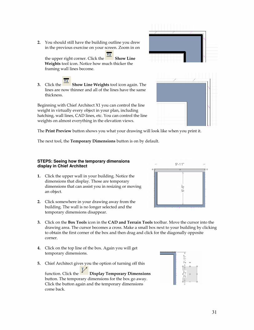
Display Tools Toolbar Let’s take a look at the Display Tools toolbar (see Figure 1-16). The Color On/Off toggle icon (the hotkey is F8) turns the color on and off in all the different views. This includes photos you have in your plan. The next tool is the Show Sheet tool. If you have your printer set up and you have your sheet size set to a certain size clicking this tool will show the sheet on your screen. Generally you don’t need to worry about this tool unless you are on a layout page. You would rarely need to use this tool while in floor plan. STEPS: Looking at the Show Line Weights tool
1. Open your CSS01-01.plan if it is not already open. If you did not create this drawing you can use CSS1-d.plan that is on the CD.
������ ��) �� 5��' ��&� ��&-��
31
2. You should still have the building outline you drew in the previous exercise on your screen. Zoom in on
the upper right corner. Click the Show Line Weights tool icon. Notice how much thicker the framing wall lines become.
3. Click the Show Line Weights tool icon again. The lines are now thinner and all of the lines have the same thickness.
Beginning with Chief Architect X1 you can control the line weight in virtually every object in your plan, including hatching, wall lines, CAD lines, etc. You can control the line weights on almost everything in the elevation views.
The Print Preview button shows you what your drawing will look like when you print it.
The next tool, the Temporary Dimensions button is on by default.
STEPS: Seeing how the temporary dimensions display in Chief Architect
1. Click the upper wall in your building. Notice the dimensions that display. Those are temporary dimensions that can assist you in resizing or moving an object.
2. Click somewhere in your drawing away from the building. The wall is no longer selected and the temporary dimensions disappear.
3. Click on the Box Tools icon in the CAD and Terrain Tools toolbar. Move the cursor into the drawing area. The cursor becomes a cross. Make a small box next to your building by clicking to obtain the first corner of the box and then drag and click for the diagonally opposite corner.
4. Click on the top line of the box. Again you will get temporary dimensions.
5. Chief Architect gives you the option of turning off this
function. Click the Display Temporary Dimensions button. The temporary dimensions for the box go away. Click the button again and the temporary dimensions come back.
32
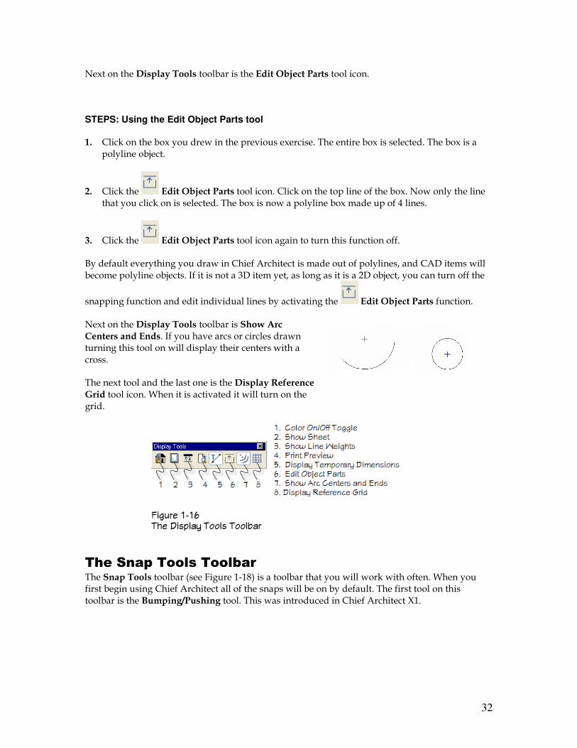
Next on the Display Tools toolbar is the Edit Object Parts tool icon.
STEPS: Using the Edit Object Parts tool
1. Click on the box you drew in the previous exercise. The entire box is selected. The box is a polyline object.
2. Click the Edit Object Parts tool icon. Click on the top line of the box. Now only the line that you click on is selected. The box is now a polyline box made up of 4 lines.
3. Click the Edit Object Parts tool icon again to turn this function off.
By default everything you draw in Chief Architect is made out of polylines, and CAD items will become polyline objects. If it is not a 3D item yet, as long as it is a 2D object, you can turn off the
snapping function and edit individual lines by activating the Edit Object Parts function.
Next on the Display Tools toolbar is Show Arc Centers and Ends. If you have arcs or circles drawn turning this tool on will display their centers with a cross.
The next tool and the last one is the Display Reference Grid tool icon. When it is activated it will turn on the grid.
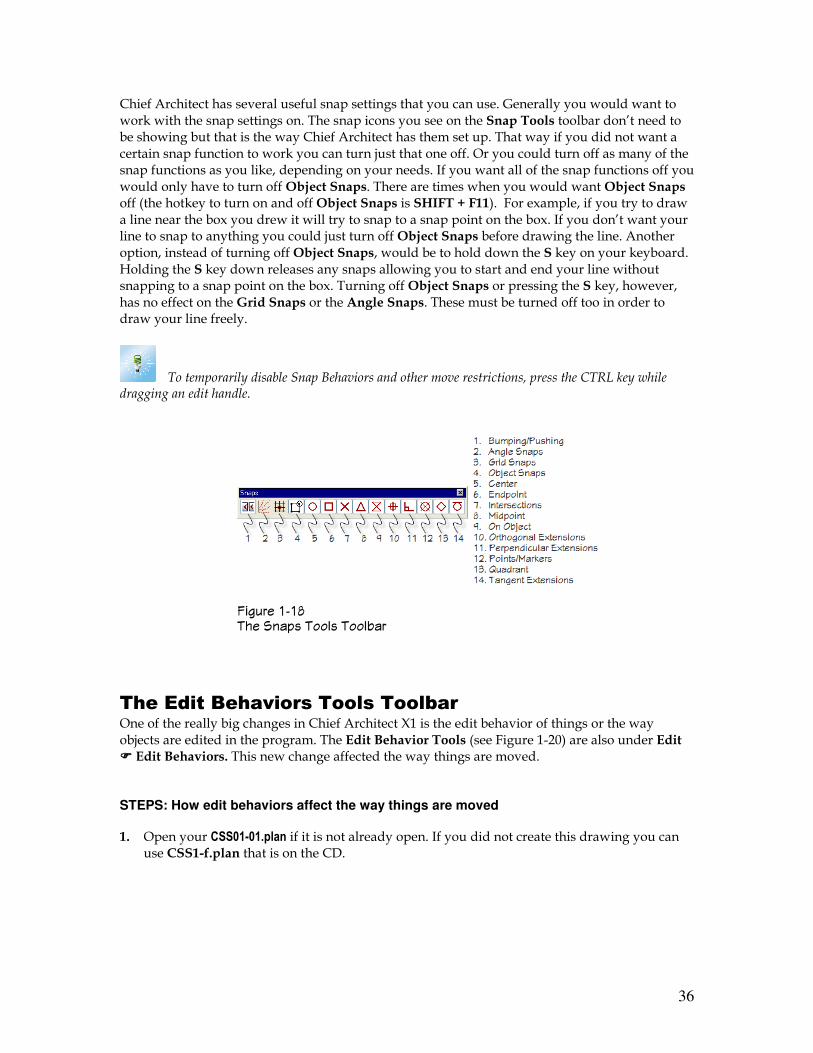
The Snap Tools Toolbar The Snap Tools toolbar (see Figure 1-18) is a toolbar that you will work with often. When you first begin using Chief Architect all of the snaps will be on by default. The first tool on this toolbar is the Bumping/Pushing tool. This was introduced in Chief Architect X1.
������ ��, �� +���&�1 ��&� ��&-��
33
STEPS: Working with the Bumping/Pushing function
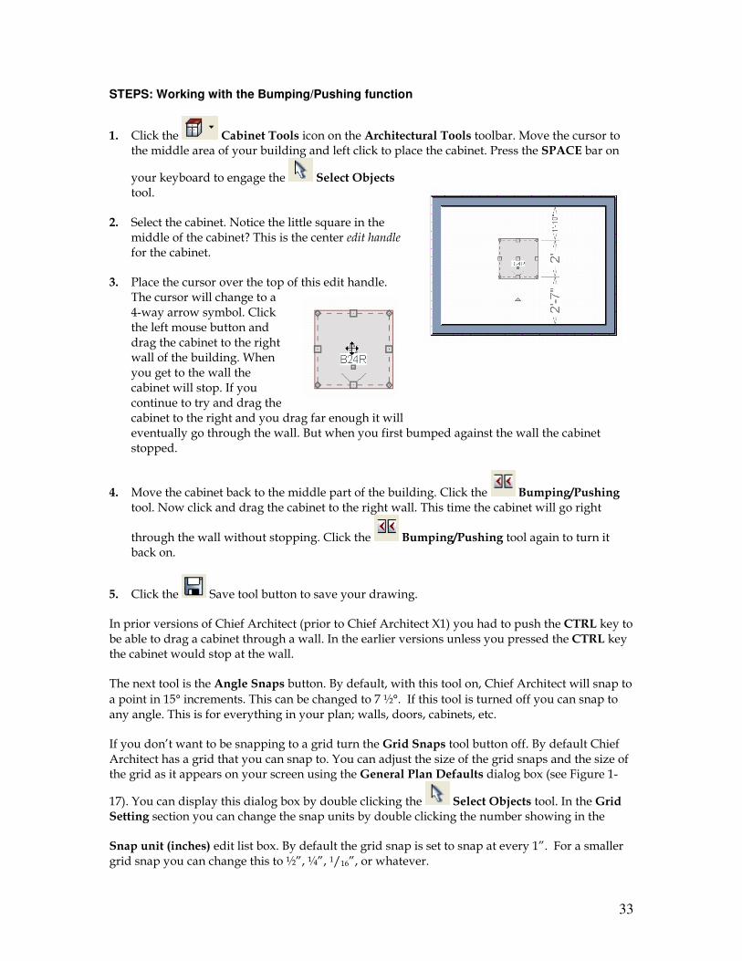
1. Click the Cabinet Tools icon on the Architectural Tools toolbar. Move the cursor to the middle area of your building and left click to place the cabinet. Press the SPACE bar on
your keyboard to engage the Select Objects tool.
2. Select the cabinet. Notice the little square in the middle of the cabinet? This is the center edit handle for the cabinet.
3. Place the cursor over the top of this edit handle. The cursor will change to a 4-way arrow symbol. Click the left mouse button and drag the cabinet to the right wall of the building. When you get to the wall the cabinet will stop. If you continue to try and drag the cabinet to the right and you drag far enough it will eventually go through the wall. But when you first bumped against the wall the cabinet stopped.
4. Move the cabinet back to the middle part of the building. Click the Bumping/Pushing tool. Now click and drag the cabinet to the right wall. This time the cabinet will go right
through the wall without stopping. Click the Bumping/Pushing tool again to turn it back on.
5. Click the Save tool button to save your drawing.
In prior versions of Chief Architect (prior to Chief Architect X1) you had to push the CTRL key to be able to drag a cabinet through a wall. In the earlier versions unless you pressed the CTRL key the cabinet would stop at the wall.
The next tool is the Angle Snaps button. By default, with this tool on, Chief Architect will snap to
a point in 15° increments. This can be changed to 7 ½°. If this tool is turned off you can snap to any angle. This is for everything in your plan; walls, doors, cabinets, etc.
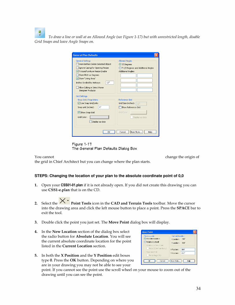
If you don’t want to be snapping to a grid turn the Grid Snaps tool button off. By default Chief Architect has a grid that you can snap to. You can adjust the size of the grid snaps and the size of the grid as it appears on your screen using the General Plan Defaults dialog box (see Figure 1-
17). You can display this dialog box by double clicking the Select Objects tool. In the Grid Setting section you can change the snap units by double clicking the number showing in the
Snap unit (inches) edit list box. By default the grid snap is set to snap at every 1”. For a smaller grid snap you can change this to ½”, ¼”, 1/16”, or whatever.
34
To draw a line or wall at an Allowed Angle (see Figure 1-17) but with unrestricted length, disable Grid Snaps and leave Angle Snaps on.
You cannot change the origin of the grid in Chief Architect but you can change where the plan starts. STEPS: Changing the location of your plan to the absolute coordinate point of 0,0
1. Open your CSS01-01.plan if it is not already open. If you did not create this drawing you can use CSS1-e.plan that is on the CD.
2. Select the Point Tools icon in the CAD and Terrain Tools toolbar. Move the cursor into the drawing area and click the left mouse button to place a point. Press the SPACE bar to exit the tool.
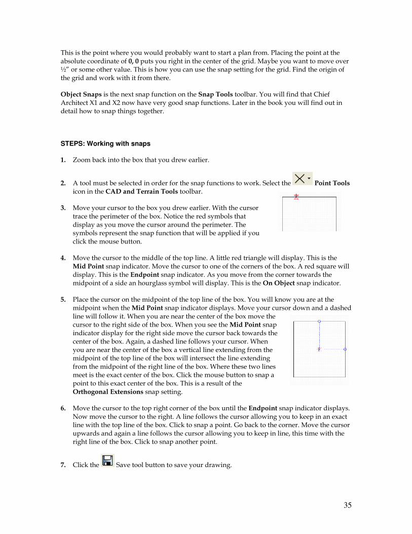
3. Double click the point you just set. The Move Point dialog box will display.
4. In the New Location section of the dialog box select the radio button for Absolute Location. You will see the current absolute coordinate location for the point listed in the Current Location section.
5. In both the X Position and the Y Position edit boxes type 0. Press the OK button. Depending on where you are in your drawing you may not be able to see your point. If you cannot see the point use the scroll wheel on your mouse to zoom out of the drawing until you can see the point.
������ ��. �� 9�����& *&�� +� ��&�� +��&�� "�#
35
This is the point where you would probably want to start a plan from. Placing the point at the absolute coordinate of 0, 0 puts you right in the center of the grid. Maybe you want to move over ½” or some other value. This is how you can use the snap setting for the grid. Find the origin of the grid and work with it from there.
Object Snaps is the next snap function on the Snap Tools toolbar. You will find that Chief Architect X1 and X2 now have very good snap functions. Later in the book you will find out in detail how to snap things together.
STEPS: Working with snaps
1. Zoom back into the box that you drew earlier.
2. A tool must be selected in order for the snap functions to work. Select the Point Tools icon in the CAD and Terrain Tools toolbar.
3. Move your cursor to the box you drew earlier. With the cursor trace the perimeter of the box. Notice the red symbols that display as you move the cursor around the perimeter. The symbols represent the snap function that will be applied if you click the mouse button.
4. Move the cursor to the middle of the top line. A little red triangle will display. This is the Mid Point snap indicator. Move the cursor to one of the corners of the box. A red square will display. This is the Endpoint snap indicator. As you move from the corner towards the midpoint of a side an hourglass symbol will display. This is the On Object snap indicator.
5. Place the cursor on the midpoint of the top line of the box. You will know you are at the midpoint when the Mid Point snap indicator displays. Move your cursor down and a dashed line will follow it. When you are near the center of the box move the cursor to the right side of the box. When you see the Mid Point snap indicator display for the right side move the cursor back towards the center of the box. Again, a dashed line follows your cursor. When you are near the center of the box a vertical line extending from the midpoint of the top line of the box will intersect the line extending from the midpoint of the right line of the box. Where these two lines meet is the exact center of the box. Click the mouse button to snap a point to this exact center of the box. This is a result of the Orthogonal Extensions snap setting.
6. Move the cursor to the top right corner of the box until the Endpoint snap indicator displays. Now move the cursor to the right. A line follows the cursor allowing you to keep in an exact line with the top line of the box. Click to snap a point. Go back to the corner. Move the cursor upwards and again a line follows the cursor allowing you to keep in line, this time with the right line of the box. Click to snap another point.
7. Click the Save tool button to save your drawing.
36
Chief Architect has several useful snap settings that you can use. Generally you would want to work with the snap settings on. The snap icons you see on the Snap Tools toolbar don’t need to be showing but that is the way Chief Architect has them set up. That way if you did not want a certain snap function to work you can turn just that one off. Or you could turn off as many of the snap functions as you like, depending on your needs. If you want all of the snap functions off you would only have to turn off Object Snaps. There are times when you would want Object Snaps off (the hotkey to turn on and off Object Snaps is SHIFT + F11). For example, if you try to draw a line near the box you drew it will try to snap to a snap point on the box. If you don’t want your line to snap to anything you could just turn off Object Snaps before drawing the line. Another option, instead of turning off Object Snaps, would be to hold down the S key on your keyboard. Holding the S key down releases any snaps allowing you to start and end your line without snapping to a snap point on the box. Turning off Object Snaps or pressing the S key, however, has no effect on the Grid Snaps or the Angle Snaps. These must be turned off too in order to draw your line freely.
To temporarily disable Snap Behaviors and other move restrictions, press the CTRL key while dragging an edit handle.
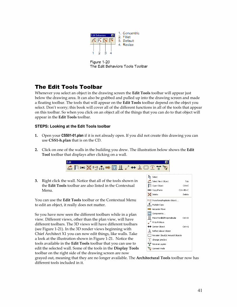
The Edit Behaviors Tools Toolbar One of the really big changes in Chief Architect X1 is the edit behavior of things or the way objects are edited in the program. The Edit Behavior Tools (see Figure 1-20) are also under Edit ���� Edit Behaviors. This new change affected the way things are moved. STEPS: How edit behaviors affect the way things are moved
1. Open your CSS01-01.plan if it is not already open. If you did not create this drawing you can use CSS1-f.plan that is on the CD.
������ ��/ �� ����� ��&� ��&-��
37
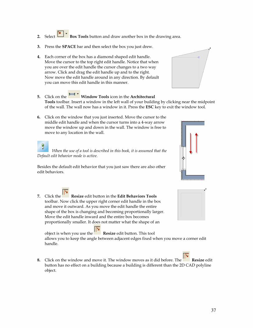
2. Select Box Tools button and draw another box in the drawing area.
3. Press the SPACE bar and then select the box you just drew.
4. Each corner of the box has a diamond shaped edit handle. Move the cursor to the top right edit handle. Notice that when you are over the edit handle the cursor changes to a two way arrow. Click and drag the edit handle up and to the right. Now move the edit handle around in any direction. By default you can move this edit handle in this manner.
5. Click on the Window Tools icon in the Architectural Tools toolbar. Insert a window in the left wall of your building by clicking near the midpoint of the wall. The wall now has a window in it. Press the ESC key to exit the window tool.
6. Click on the window that you just inserted. Move the cursor to the middle edit handle and when the cursor turns into a 4-way arrow move the window up and down in the wall. The window is free to move to any location in the wall.
When the use of a tool is described in this book, it is assumed that the Default edit behavior mode is active.
Besides the default edit behavior that you just saw there are also other edit behaviors.
7. Click the Resize edit button in the Edit Behaviors Tools toolbar. Now click the upper right corner edit handle in the box and move it outward. As you move the edit handle the entire shape of the box is changing and becoming proportionally larger. Move the edit handle inward and the entire box becomes proportionally smaller. It does not matter what the shape of an
object is when you use the Resize edit button. This tool allows you to keep the angle between adjacent edges fixed when you move a corner edit handle.
8. Click on the window and move it. The window moves as it did before. The Resize edit button has no effect on a building because a building is different than the 2D CAD polyline object.
38
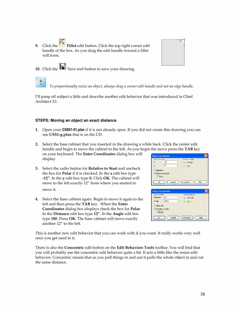
9. Click the Fillet edit button. Click the top right corner edit handle of the box. As you drag the edit handle inward a fillet will form.
10. Click the Save tool button to save your drawing.
To proportionally resize an object, always drag a corner edit handle and not an edge handle.
I’ll jump off subject a little and describe another edit behavior that was introduced in Chief Architect X1.
STEPS: Moving an object an exact distance
1. Open your CSS01-01.plan if it is not already open. If you did not create this drawing you can use CSS1-g.plan that is on the CD.
2. Select the base cabinet that you inserted in the drawing a while back. Click the center edit handle and begin to move the cabinet to the left. As you begin the move press the TAB key on your keyboard. The Enter Coordinates dialog box will display.
3. Select the radio button for Relative to Start and uncheck the box for Polar if it is checked. In the x edit box type -12”. In the y edit box type 0. Click OK. The cabinet will move to the left exactly 12” from where you started to
move it.
4. Select the base cabinet again. Begin to move it again to the left and then press the TAB key. When the Enter Coordinates dialog box displays check the box for Polar. In the Distance edit box type 12”. In the Angle edit box type 180. Press OK. The base cabinet will move exactly another 12” to the left.
This is another new edit behavior that you can work with if you want. It really works very well once you get used to it.
There is also the Concentric edit button on the Edit Behaviors Tools toolbar. You will find that you will probably use the concentric edit behavior quite a bit. It acts a little like the resize edit behavior. Concentric means that as you pull things in and out it pulls the whole object in and out the same distance.
39
STEPS: Working with the Concentric edit behavior
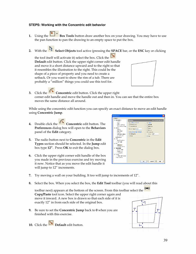
1. Using the Box Tools button draw another box on your drawing. You may have to use the pan function to pan the drawing to an empty space to put the box.
2. With the Select Objects tool active (pressing the SPACE bar, or the ESC key or clicking
the tool itself will activate it) select the box. Click the Default edit button. Click the upper right corner edit handle and move it a short distance upward and to the right so that it resembles the illustration to the right. This could be the shape of a piece of property and you need to create a setback. Or you want to show the rim of a tub. There are probably a “million” things you could use this tool for.
3. Click the Concentric edit button. Click the upper right corner edit handle and move the handle out and then in. You can see that the entire box moves the same distance all around.
While using the concentric edit function you can specify an exact distance to move an edit handle using Concentric Jump.
4. Double click the Concentric edit button. The Preferences dialog box will open to the Behaviors panel of the Edit category.
5. The radio button next to Concentric in the Edit Types section should be selected. In the Jump edit box type 12”. Press OK to exit the dialog box.
6. Click the upper right corner edit handle of the box you made in the previous exercise and try moving it now. Notice that as you move the edit handle it will jump to 12” increments.
7. Try moving a wall on your building. It too will jump to increments of 12”.
8. Select the box. When you select the box, the Edit Tool toolbar (you will read about this
toolbar next) appears at the bottom of the screen. From this toolbar select the Copy/Paste tool icon. Select the upper right corner again and move it inward. A new box is drawn so that each side of it is exactly 12” in from each side of the original box.
9. Be sure to set the Concentric Jump back to 0 when you are finished with this exercise.
10. Click the Default edit button.
40
11. Click the Save tool button to save your drawing.
To concentrically resize an object with no restrictions, set the Concentric Jump value on the Edit Behaviors panel of the Preferences dialog to zero and turn off Grid Snaps
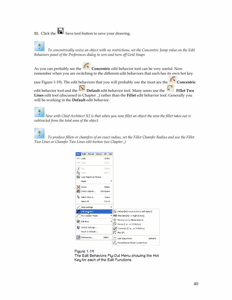
As you can probably see the Concentric edit behavior tool can be very useful. Now remember when you are switching to the different edit behaviors that each has its own hot key
(see Figure 1-19). The edit behaviors that you will probably use the most are the Concentric
edit behavior tool and the Default edit behavior tool. Many users use the Fillet Two Lines edit tool (discussed in Chapter _) rather than the Fillet edit behavior tool. Generally you will be working in the Default edit behavior.
New with Chief Architect X2 is that when you now fillet an object the area the fillet takes out is subtracted from the total area of the object.
To produce fillets or chamfers of an exact radius, set the Fillet Chamfer Radius and use the Fillet Two Lines or Chamfer Two Lines edit button (see Chapter_)
������ ��4 �� :��� "���8���� �&1��� ���� ���'��� ��� ��� 0�1 �� ���� � ��� :��� ���������
41
The Edit Tools Toolbar Whenever you select an object in the drawing screen the Edit Tools toolbar will appear just below the drawing area. It can also be grabbed and pulled up into the drawing screen and made a floating toolbar. The tools that will appear on the Edit Tools toolbar depend on the object you select. Don’t worry; this book will cover all of the different functions in all of the tools that appear on this toolbar. So when you click on an object all of the things that you can do to that object will appear in the Edit Tools toolbar.
STEPS: Looking at the Edit Tools toolbar
1. Open your CSS01-01.plan if it is not already open. If you did not create this drawing you can use CSS1-h.plan that is on the CD.
2. Click on one of the walls in the building you drew. The illustration below shows the Edit Tool toolbar that displays after clicking on a wall.
3. Right click the wall. Notice that all of the tools shown in
the Edit Tools toolbar are also listed in the Contextual Menu.
You can use the Edit Tools toolbar or the Contextual Menu to edit an object, it really does not matter. So you have now seen the different toolbars while in a plan view. Different views, other than the plan view, will have different toolbars. The 3D views will have different toolbars (see Figure 1-21). In the 3D render views beginning with Chief Architect X1 you can now edit things, like walls. Take a look at the illustration shown in Figure 1-21. Notice the tools available in the Edit Tools toolbar that you can use to edit the selected wall. Some of the tools in the Display Tools toolbar on the right side of the drawing screen are now grayed out, meaning that they are no longer available. The Architectural Tools toolbar now has different tools included in it.
������ ��6 �� :��� "���8���� ��&� ��&-��
42
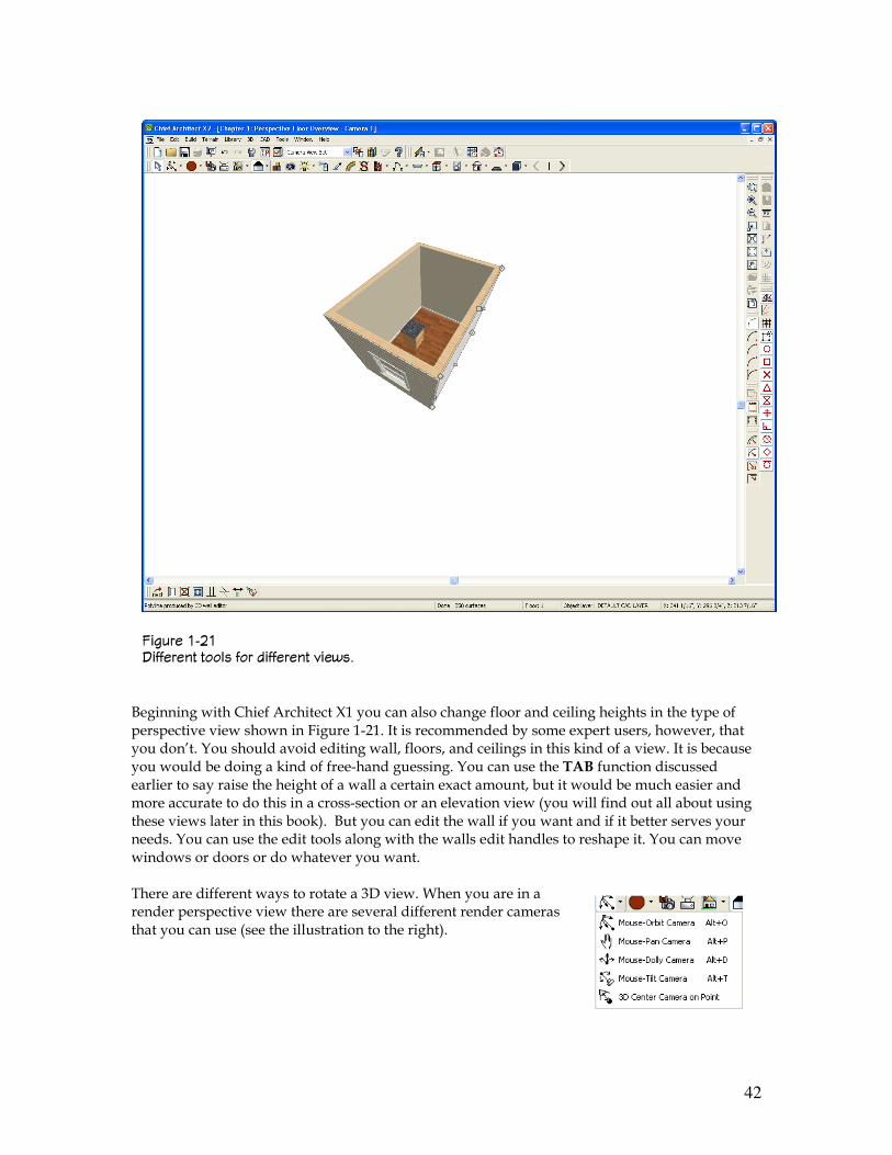
������ ��� +� ����� ���&� �� �� ����� 8��'�;
Beginning with Chief Architect X1 you can also change floor and ceiling heights in the type of perspective view shown in Figure 1-21. It is recommended by some expert users, however, that you don’t. You should avoid editing wall, floors, and ceilings in this kind of a view. It is because you would be doing a kind of free-hand guessing. You can use the TAB function discussed earlier to say raise the height of a wall a certain exact amount, but it would be much easier and more accurate to do this in a cross-section or an elevation view (you will find out all about using these views later in this book). But you can edit the wall if you want and if it better serves your needs. You can use the edit tools along with the walls edit handles to reshape it. You can move windows or doors or do whatever you want. There are different ways to rotate a 3D view. When you are in a render perspective view there are several different render cameras that you can use (see the illustration to the right).
43
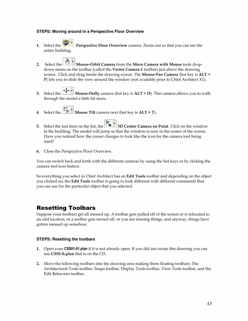
STEPS: Moving around in a Perspective Floor Overview
1. Select the Perspective Floor Overview camera. Zoom out so that you can see the entire building.
2. Select the Mouse-Orbit Camera from the Move Camera with Mouse tools drop-down menu on the toolbar (called the Vector Camera 1 toolbar) just above the drawing screen. Click and drag inside the drawing screen. The Mouse-Pan Camera (hot key is ALT + P) lets you to slide the view around the window (not available prior to Chief Architect X1).
3. Select the Mouse-Dolly camera (hot key is ALT + D). This camera allows you to walk through the model a little bit more.
4. Select the Mouse Tilt camera next (hot key is ALT + T).
5. Select the last item on the list, the 3D Center Camera on Point. Click on the window in the building. The model will jump so that the window is now in the center of the screen. Have you noticed how the cursor changes to look like the icon for the camera tool being used?
6. Close the Perspective Floor Overview.
You can switch back and forth with the different cameras by using the hot keys or by clicking the camera tool icon button.
So everything you select in Chief Architect has an Edit Tools toolbar and depending on the object you clicked on, the Edit Tools toolbar is going to look different with different commands that you can use for the particular object that you selected.
Resetting Toolbars
Suppose your toolbars get all messed up. A toolbar gets pulled off of the screen or is relocated to an odd location, or a toolbar gets turned off, or you are missing things, and anyway, things have gotten messed up somehow. STEPS: Resetting the toolbars 1. Open your CSS01-01.plan if it is not already open. If you did not create this drawing you can
use CSS1-h.plan that is on the CD.
2. Move the following toolbars into the drawing area making them floating toolbars: The Architectural Tools toolbar, Snaps toolbar, Display Tools toolbar, View Tools toolbar, and the Edit Behaviors toolbar.
44
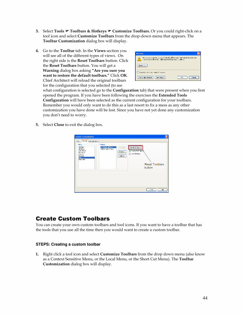
3. Select Tools ���� Toolbars & Hotkeys ���� Customize Toolbars. Or you could right-click on a tool icon and select Customize Toolbars from the drop-down menu that appears. The Toolbar Customization dialog box will display.
4. Go to the Toolbar tab. In the Views section you will see all of the different types of views. On the right side is the Reset Toolbars button. Click the Reset Toolbars button. You will get a Warning dialog box asking “Are you sure you want to restore the default toolbars.” Click OK. Chief Architect will reload the original toolbars for the configuration that you selected (to see what configuration is selected go to the Configuration tab) that were present when you first opened the program. If you have been following the exercises the Extended Tools Configuration will have been selected as the current configuration for your toolbars. Remember you would only want to do this as a last resort to fix a mess as any other customization you have done will be lost. Since you have not yet done any customization you don’t need to worry.
5. Select Close to exit the dialog box.
Create Custom Toolbars
You can create your own custom toolbars and tool icons. If you want to have a toolbar that has the tools that you use all the time then you would want to create a custom toolbar. STEPS: Creating a custom toolbar 1. Right click a tool icon and select Customize Toolbars from the drop down menu (also know
as a Context Sensitive Menu, or the Local Menu, or the Short Cut Menu). The Toolbar Customization dialog box will display.
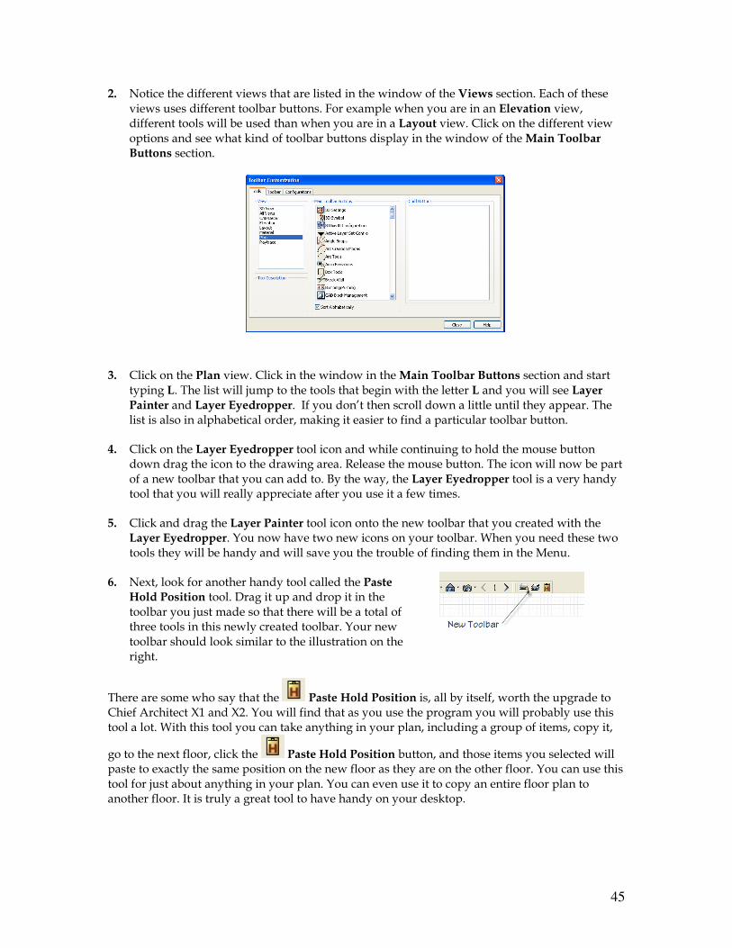
45
2. Notice the different views that are listed in the window of the Views section. Each of these views uses different toolbar buttons. For example when you are in an Elevation view, different tools will be used than when you are in a Layout view. Click on the different view options and see what kind of toolbar buttons display in the window of the Main Toolbar Buttons section.
3. Click on the Plan view. Click in the window in the Main Toolbar Buttons section and start
typing L. The list will jump to the tools that begin with the letter L and you will see Layer Painter and Layer Eyedropper. If you don’t then scroll down a little until they appear. The list is also in alphabetical order, making it easier to find a particular toolbar button.
4. Click on the Layer Eyedropper tool icon and while continuing to hold the mouse button down drag the icon to the drawing area. Release the mouse button. The icon will now be part of a new toolbar that you can add to. By the way, the Layer Eyedropper tool is a very handy tool that you will really appreciate after you use it a few times.
5. Click and drag the Layer Painter tool icon onto the new toolbar that you created with the Layer Eyedropper. You now have two new icons on your toolbar. When you need these two tools they will be handy and will save you the trouble of finding them in the Menu.
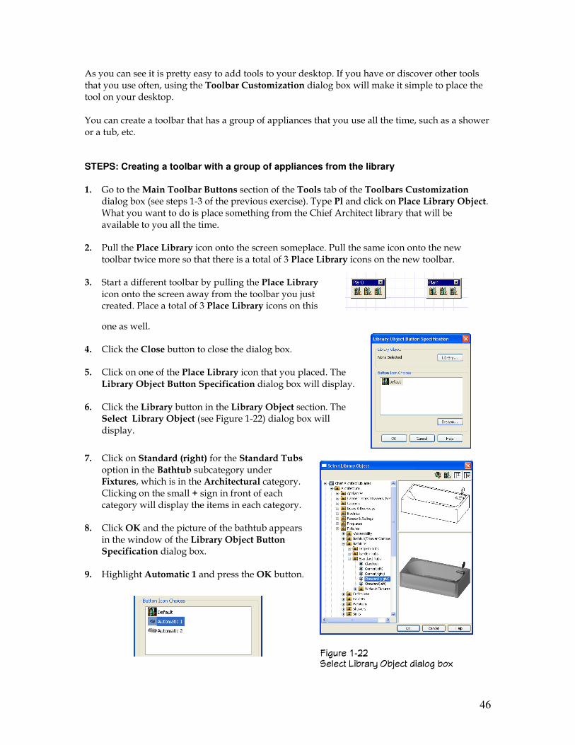
6. Next, look for another handy tool called the Paste Hold Position tool. Drag it up and drop it in the toolbar you just made so that there will be a total of three tools in this newly created toolbar. Your new toolbar should look similar to the illustration on the right.
There are some who say that the Paste Hold Position is, all by itself, worth the upgrade to Chief Architect X1 and X2. You will find that as you use the program you will probably use this tool a lot. With this tool you can take anything in your plan, including a group of items, copy it,
go to the next floor, click the Paste Hold Position button, and those items you selected will paste to exactly the same position on the new floor as they are on the other floor. You can use this tool for just about anything in your plan. You can even use it to copy an entire floor plan to another floor. It is truly a great tool to have handy on your desktop.
46
As you can see it is pretty easy to add tools to your desktop. If you have or discover other tools that you use often, using the Toolbar Customization dialog box will make it simple to place the tool on your desktop. You can create a toolbar that has a group of appliances that you use all the time, such as a shower or a tub, etc. STEPS: Creating a toolbar with a group of appliances from the library 1. Go to the Main Toolbar Buttons section of the Tools tab of the Toolbars Customization
dialog box (see steps 1-3 of the previous exercise). Type Pl and click on Place Library Object. What you want to do is place something from the Chief Architect library that will be available to you all the time.
2. Pull the Place Library icon onto the screen someplace. Pull the same icon onto the new toolbar twice more so that there is a total of 3 Place Library icons on the new toolbar.
3. Start a different toolbar by pulling the Place Library icon onto the screen away from the toolbar you just created. Place a total of 3 Place Library icons on this
one as well.
4. Click the Close button to close the dialog box.
5. Click on one of the Place Library icon that you placed. The Library Object Button Specification dialog box will display.
6. Click the Library button in the Library Object section. The Select Library Object (see Figure 1-22) dialog box will display.
7. Click on Standard (right) for the Standard Tubs option in the Bathtub subcategory under Fixtures, which is in the Architectural category. Clicking on the small + sign in front of each category will display the items in each category.
8. Click OK and the picture of the bathtub appears in the window of the Library Object Button Specification dialog box.
9. Highlight Automatic 1 and press the OK button.
������ ��� ��&��� %�-���1 �-<��� ���&�� -�#
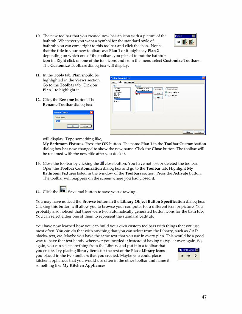
47
10. The new toolbar that you created now has an icon with a picture of the
bathtub. Whenever you want a symbol for the standard style of bathtub you can come right to this toolbar and click the icon. Notice that the title in your new toolbar says Plan 1 or it might say Plan 2 depending on which one of the toolbars you picked to put the bathtub icon in. Right click on one of the tool icons and from the menu select Customize Toolbars. The Customize Toolbars dialog box will display.
11. In the Tools tab, Plan should be highlighted in the Views section. Go to the Toolbar tab. Click on Plan 1 to highlight it.
12. Click the Rename button. The Rename Toolbar dialog box
will display. Type something like, My Bathroom Fixtures. Press the OK button. The name Plan 1 in the Toolbar Customization dialog box has now changed to show the new name. Click the Close button. The toolbar will be renamed with the new title after you dock it.
13. Close the toolbar by clicking the close button. You have not lost or deleted the toolbar. Open the Toolbar Customization dialog box and go to the Toolbar tab. Highlight My Bathroom Fixtures listed in the window of the Toolbars section. Press the Activate button. The toolbar will reappear on the screen where you had closed it.
14. Click the Save tool button to save your drawing.
You may have noticed the Browse button in the Library Object Button Specification dialog box. Clicking this button will allow you to browse your computer for a different icon or picture. You probably also noticed that there were two automatically generated button icons for the bath tub. You can select either one of them to represent the standard bathtub.
You have now learned how you can build your own custom toolbars with things that you use most often. You can do that with anything that you can select from the Library, such as CAD blocks, text, etc. Maybe you have the same text that you use in every plan. This would be a good way to have that text handy whenever you needed it instead of having to type it over again. So, again, you can select anything from the Library and put it in a toolbar that you create. Try placing library items for the rest of the Place Library icons you placed in the two toolbars that you created. Maybe you could place kitchen appliances that you would use often in the other toolbar and name it something like My Kitchen Appliances.
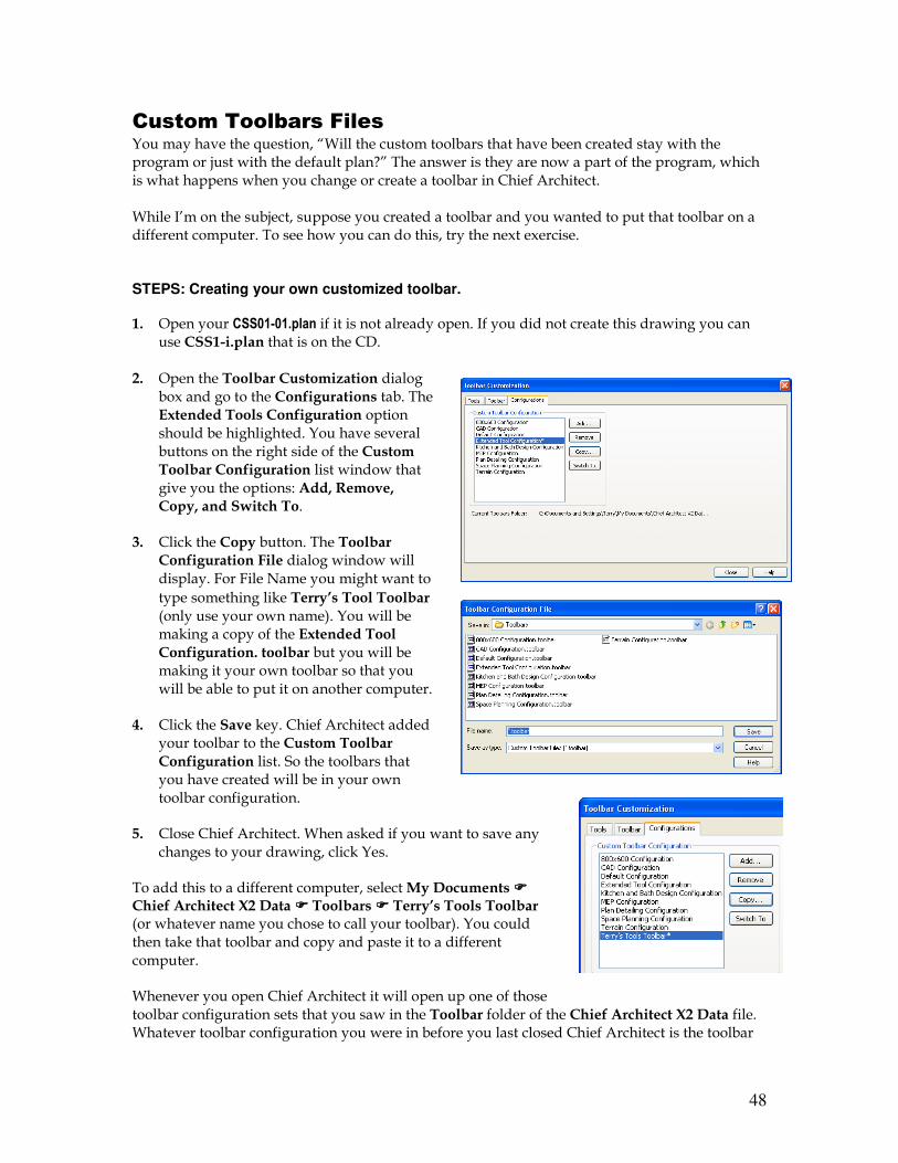
48
Custom Toolbars Files
You may have the question, “Will the custom toolbars that have been created stay with the program or just with the default plan?” The answer is they are now a part of the program, which is what happens when you change or create a toolbar in Chief Architect. While I’m on the subject, suppose you created a toolbar and you wanted to put that toolbar on a different computer. To see how you can do this, try the next exercise. STEPS: Creating your own customized toolbar.
1. Open your CSS01-01.plan if it is not already open. If you did not create this drawing you can use CSS1-i.plan that is on the CD.
2. Open the Toolbar Customization dialog
box and go to the Configurations tab. The Extended Tools Configuration option should be highlighted. You have several buttons on the right side of the Custom Toolbar Configuration list window that give you the options: Add, Remove, Copy, and Switch To.
3. Click the Copy button. The Toolbar Configuration File dialog window will display. For File Name you might want to
type something like Terry’s Tool Toolbar (only use your own name). You will be making a copy of the Extended Tool Configuration. toolbar but you will be making it your own toolbar so that you will be able to put it on another computer.
4. Click the Save key. Chief Architect added your toolbar to the Custom Toolbar Configuration list. So the toolbars that you have created will be in your own toolbar configuration.
5. Close Chief Architect. When asked if you want to save any changes to your drawing, click Yes.
To add this to a different computer, select My Documents ���� Chief Architect X2 Data ���� Toolbars ���� Terry’s Tools Toolbar (or whatever name you chose to call your toolbar). You could then take that toolbar and copy and paste it to a different computer.
Whenever you open Chief Architect it will open up one of those toolbar configuration sets that you saw in the Toolbar folder of the Chief Architect X2 Data file. Whatever toolbar configuration you were in before you last closed Chief Architect is the toolbar
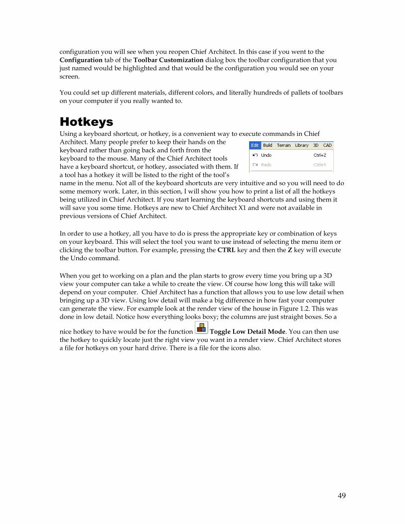
49
configuration you will see when you reopen Chief Architect. In this case if you went to the Configuration tab of the Toolbar Customization dialog box the toolbar configuration that you just named would be highlighted and that would be the configuration you would see on your screen.
You could set up different materials, different colors, and literally hundreds of pallets of toolbars on your computer if you really wanted to.
Hotkeys
Using a keyboard shortcut, or hotkey, is a convenient way to execute commands in Chief Architect. Many people prefer to keep their hands on the keyboard rather than going back and forth from the keyboard to the mouse. Many of the Chief Architect tools have a keyboard shortcut, or hotkey, associated with them. If a tool has a hotkey it will be listed to the right of the tool’s name in the menu. Not all of the keyboard shortcuts are very intuitive and so you will need to do some memory work. Later, in this section, I will show you how to print a list of all the hotkeys being utilized in Chief Architect. If you start learning the keyboard shortcuts and using them it will save you some time. Hotkeys are new to Chief Architect X1 and were not available in previous versions of Chief Architect.
In order to use a hotkey, all you have to do is press the appropriate key or combination of keys on your keyboard. This will select the tool you want to use instead of selecting the menu item or clicking the toolbar button. For example, pressing the CTRL key and then the Z key will execute the Undo command.
When you get to working on a plan and the plan starts to grow every time you bring up a 3D view your computer can take a while to create the view. Of course how long this will take will depend on your computer. Chief Architect has a function that allows you to use low detail when bringing up a 3D view. Using low detail will make a big difference in how fast your computer can generate the view. For example look at the render view of the house in Figure 1.2. This was done in low detail. Notice how everything looks boxy; the columns are just straight boxes. So a
nice hotkey to have would be for the function Toggle Low Detail Mode. You can then use the hotkey to quickly locate just the right view you want in a render view. Chief Architect stores a file for hotkeys on your hard drive. There is a file for the icons also.
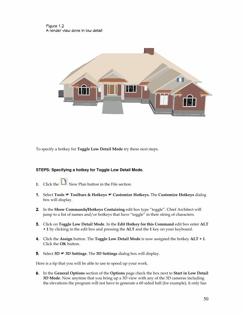
50
To specify a hotkey for Toggle Low Detail Mode try these next steps.
STEPS: Specifying a hotkey for Toggle Low Detail Mode.
1. Click the New Plan button in the File section.
�;�;�;�; Select Tools ���� Toolbars & Hotkeys ���� Customize Hotkeys. The Customize Hotkeys dialog box will display.
�;�;�;�; In the Show Commands/Hotkeys Containing edit box type “toggle”. Chief Architect will jump to a list of names and/or hotkeys that have “toggle” in their string of characters.
�;�;�;�; Click on Toggle Low Detail Mode. In the Edit Hotkey for this Command edit box enter ALT + 1 by clicking in the edit box and pressing the ALT and the 1 key on your keyboard.
$;$;$;$; Click the Assign button. The Toggle Low Detail Mode is now assigned the hotkey ALT + 1. Click the OK button.
);););); Select 3D ���� 3D Settings. The 3D Settings dialog box will display.
Here is a tip that you will be able to use to speed up your work.
,;,;,;,; In the General Options section of the Options page check the box next to Start in Low Detail 3D Mode. Now anytime that you bring up a 3D view with any of the 3D cameras including the elevations the program will not have to generate a 60 sided ball (for example), it only has
������ �;� � ������ 8��' ���� �� &�' �����&
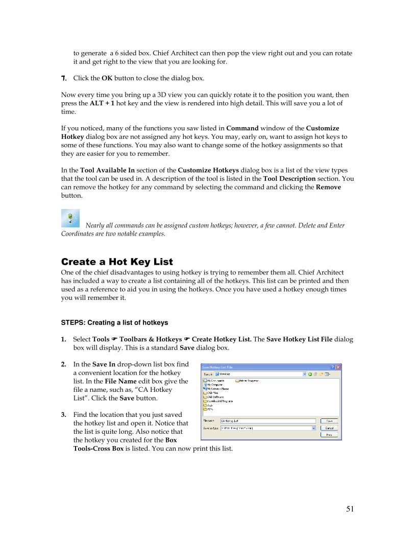
51
to generate a 6 sided box. Chief Architect can then pop the view right out and you can rotate it and get right to the view that you are looking for.
.;.;.;.; Click the OK button to close the dialog box.
Now every time you bring up a 3D view you can quickly rotate it to the position you want, then press the ALT + 1 hot key and the view is rendered into high detail. This will save you a lot of time.
If you noticed, many of the functions you saw listed in Command window of the Customize Hotkey dialog box are not assigned any hot keys. You may, early on, want to assign hot keys to some of these functions. You may also want to change some of the hotkey assignments so that they are easier for you to remember.
In the Tool Available In section of the Customize Hotkeys dialog box is a list of the view types that the tool can be used in. A description of the tool is listed in the Tool Description section. You can remove the hotkey for any command by selecting the command and clicking the Remove button.
Nearly all commands can be assigned custom hotkeys; however, a few cannot. Delete and Enter Coordinates are two notable examples.
Create a Hot Key List One of the chief disadvantages to using hotkey is trying to remember them all. Chief Architect has included a way to create a list containing all of the hotkeys. This list can be printed and then used as a reference to aid you in using the hotkeys. Once you have used a hotkey enough times you will remember it. STEPS: Creating a list of hotkeys 1. Select Tools ���� Toolbars & Hotkeys ���� Create Hotkey List. The Save Hotkey List File dialog
box will display. This is a standard Save dialog box.
2. In the Save In drop-down list box find a convenient location for the hotkey list. In the File Name edit box give the file a name, such as, “CA Hotkey List”. Click the Save button.
3. Find the location that you just saved the hotkey list and open it. Notice that the list is quite long. Also notice that the hotkey you created for the Box Tools-Cross Box is listed. You can now print this list.
52
The ESC Key as a Hotkey
The ESC key has a special function introduced in Chief Architect X2. Using the ESC key as a hotkey, you have the ability to restore previous commands. To see how this works try this next exercise. STEPS: Using the ESC key function.
1. Select the Base Cabinet tool and click in a blank drawing area to place a base cabinet.
2. Select the Wall Cabinet tool and place it in the drawing next to the base cabinet.
3. Select the Full Height cabinet tool and place it near the other two cabinets.
4. After placing the full height cabinet Chief Architect is waiting for you to place another full height cabinet unless you select a different tool. Press the ESC key on your keyboard. You are switched back to the wall cabinet command, which was the previous command. You can now place another wall cabinet. If you press the ESC key again you are switched back to the next previous command, which was the base cabinet command.
5. Press SHIFT + ESC. You now go forward to the wall cabinet command. Press SHIFT+ESC again to go forward another command, which is the full height cabinet command.
6. Select the Select Objects tool and use this tool to select the base cabinet. Press the ESC key. The base cabinet is deselected. Press the ESC key again without selecting anything. You are switched to the previous command, the full height cabinet command.

53

54