ch02 r2 stec autopilot - cirrus design authorized service...
TRANSCRIPT

CHAPTER
S-TEC SYSTEM 55X
SYSTEM 20/30 AUTOPILOT
Rev. 2 15 March, 2004
CHAPTER 2- AUTOPILOT
Description/Scope: This chapter is a comprehensive troubleshooting guide for all Cirrus aircraft equipped with an autopilot. There are currently four different autopilot systems available with Cirrus aircraft, all manufactured by S-Tec Corporation. The four models are as follows: System 20, System 30, System 55X and System 55SR. WARNING: This troubleshooting guide is not F.A.A. approved and is provided as a reference only. The F.A.A. approved maintenance and service procedures are found in official Cirrus Design maintenance manuals and service bulletins. All procedures documented in this guide are to be performed by certified maintenance personnel. General Guidelines:
1. Begin the troubleshooting process by discussing the problem with the pilot and with experienced avionics technicians to help define the problem.
2. Perform the setup procedures in section 2.1 of this chapter.
3. Perform the pre-troubleshooting test procedures for the model autopilot
being diagnosed. System 55X test procedures are located at the beginning of section 2 of this chapter. System 20/30 test procedures are located at the beginning of section 3 of this chapter.
4. Consult this document as a diagnostic guide to the most common and
recurring problems, causes and solutions. It is recommended to proceed from the simplest solution to the most complex.
Chapter Organization: This chapter is broken up into four sections, each dealing with one particular autopilot system. The first section focuses on the System 55X, the second section focuses on the System 20, the third focuses on the System 30, and the fourth focuses on the System 55SR. Contact Information: Cirrus Design technical support line: 1-800-279-4322.

Rev. 2 15 March, 2004
CHAPTER 2- AUTOPILOT
Table of Contents Subject Section Page Sandel HSI Setup Procedures 2.1 1 Garmin GNS 430 Setup Procedures 2.1 2 System 55X Autopilot 2.2 1 System 55X Pretroubleshooting Procedures 2.2 5 System 55X Pretroubleshooting Checklist 2.2 8 System 55X Vertical Hold Failure 2.2 9 System 55X Roll Control Failure 2.2 12 System 55X Tracking Failure 2.2 16 System 55X Miscellaneous 2.2 21 System 20/30 Autopilot 2.3 1 System 20/30 Pretroubleshooting Procedures 2.3 5 System 20/30 Pretroubleshooting Checklist 2.3 8 System 30 Vertical Hold Failure 2.3 9 System 20/30 Roll Control Failure 2.3 12 System 20/30 Tracking Failure 2.3 16 System 20/30 Miscellaneous 2.3 21

Rev. 2 5 March, 2004 Section 2.1 Page 1
2.1- SETUP PROCEDURES
Introduction: This section points out main instrument settings that when set incorrectly, can cause the autopilot to operate incorrectly. These settings should always be checked before troubleshooting any further. Each subsection applies to the setup of a different instrument. Sandel EHSI:
1. Activate the Sandel HSI, while holding down both the SHFT key and the A-B key simultaneously.
2. Press the NEXT or LAST keys to select pages.
3. Select setup page 8.
4. Ensure that the Current Selection is set to CENTURY 21/31/41
DC.
5. Select setup page 9.
6. Ensure that all the numbers on this page are the same, and that they are pink. Reference volts should be at 4.95 Volts.
7. Select setup page 10.
8. Ensure that the Current Selection is set to Garmin GNS
430(ARINC).
9. Select setup page 12.
10. The two main entries should read Garmin GNS 430 (ARINC) and NONE, respectively. If the secondary entry does not read NONE, select page11, and ensure that the Current Selection is NONE.
11. In the first section on page 12, ensure that all entries are set properly. The ANNUN entry should be SERIAL. The COURSE entry should be OBS/LEG. The DEVIATION entry should be SER DATA. The OBS ROT should be NORMAL. The OBS CAL should read 0 degrees.
Omit this section if the aircraft is not equipped with a Sandel EHSI.

Rev. 2 5 March, 2004 Section 2.1 Page 2
12. Select setup page 15.
13. Ensure that the ILS Lockout setting is set to NO.
Garmin GNS430:
1. Power up the GNS430 unit while holding down the ENT key.
2. Rotate the small right knob to switch between pages.
3. Change to the MAIN ARINC 429 CONFIG page.
4. Ensure that IN1 is set to Sandel EHSI under the DATA column.
5. Ensure that IN2 is set to Off under the DATA column.
6. Ensure that OUT is set to GAMA429 grph w/int.

Rev. 2 5 March, 2004 Section 2.2 Page 1
2.2- SYSTEM 55X AUTOPILOT
Description: The S-TEC System 55X autopilot is installed in the SR20 C model, SR20 PFD model, as well as all SR22 model B and above. The system includes a flight guidance computer, an altitude selector/alerter (optional), an altitude transducer, and a turn coordinator. Heading, course, and course deviation information are obtained through the HSI. The autopilot executes roll commands using the aircraft's roll trim system. In the SR20, the autopilot pitch commands are executed through the pitch trim system in the aircraft. In the SR22, the autopilot pitch commands are executed through a dedicated pitch servo. Performance Characteristics:
• Heading mode: In heading mode, the System 55X follows the heading bug using standard turn rates. While in heading mode, the autopilot is not monitoring any navigation aid, so course deviation from wind drift is possible.
• NAV Intercept and Tracking: When in Nav mode, the System 55X will
track a VOR or GPS course. At full CDI needle deflection, the autopilot will fly at a 45 degree intercept with the desired course. The intercept angle will gradually shallow as the course is acquired. During course acquisition, the autopilot will turn at a rate of up to 90% of the standard turn rate. When a course is acquired, the CAP annunciator on the autopilot will illuminate. During this time, the autopilot has successfully captured the course, and is calculating wind correction angles. After 15 seconds, the CAP annunciator will disappear, and the autopilot will turn to low sensitivity level. In low sensitivity level, the maximum rate of turn will reduce to 45% of the standard rate.
• Soft mode: Soft mode is activated in NAV mode when a course is
followed consistently for approximately one minute. In soft mode, the autopilot will turn at a rate of up to 15% of the standard rate. The aircraft will remain in soft mode while the CDI shows less than 10% deviation.
• User Selectable intercept angles: When an intercept angle is selected,
the autopilot will fly the custom angle until the aircraft nears the desired course. If an angle greater than 45 degrees is selected, the aircraft may overshoot the course.
• GPSS Mode: While in GPSS mode, the autopilot behaves in a similar
fashion to NAV mode. Note that the autopilot has the capability of

Rev. 2 5 March, 2004 Section 2.2 Page 2
executing turns up to 30% greater than the standard turn rate in GPSS mode.
• Altitude Hold Mode: When alt hold mode is engaged, the aircraft will
maintain the current altitude. The pilot may choose to have the autopilot maintain another altitude within 360 feet of the current altitude.
• ILS Tracking: In approach mode, the autopilot behaves in a similar
fashion to NAV mode. In approach mode, the autopilot is at it’s maximum sensitivity.
• Glideslope Tracking: In order for the autopilot to track a glideslope, the
following conditions must be met: o The glideslope signal must be valid. o The CDI must be within 50% needle deflection for the
ILS signal. o The aircraft must be 60% below the Glideslope
centerline.
• Localizer Back Course Tracking: Operation in this mode is identical to operation in approach mode.
Documentation Available:
• S-TEC Corporation System 55X Pilot's Operating Handbook. Available online at: www.s-tec.com/manuals.html.
• S-TEC Corporation ST-360 Altitude Selector/Alerter Pilot's Operating
Handbook. Available online at: www.s-tec.com/manuals.html.

Rev. 2 5 March, 2004 Section 2.2 Page 3
System 55X Autopilot Quick Troubleshooting Reference Failure Category Failure Mode Potentially Responsible System Autopilot Troubleshooting Guide Ref. SR20/22 AMM Ref.
Vertical Hold Cannot Hold Altitude AP Pitch Trim Relay Section 2.2.4 Pitch Servo Section 2.2.4 22-11 (SR22 Only) Altitude Transducer Section 2.2.4 22-12/22-11 Autopilot wiring Section 2.2.4 22-12/22-11 (WM) 55X Autopilot Computer Section 2.2.4 22-12/22-11
Vertical Hold Porpoising in Alt Hold Altitude Transducer Section 2.2.4 22-12/22-11 Water in Pitot/Static Section 2.2.4 34-10/34-10 Pitch Trim Cartridge Section 2.2.4 27-30/27-30 Elevator Rigging Section 2.2.4 27-30/27-30 Autopilot wiring Section 2.2.4 22-12/22-11 (WM) 55X Autopilot Computer Section 2.2.4 22-12/22-11
Roll Control Roll Oscillation Roll Trim Tab Section 2.2.5 27-10/27-10 Autopilot Gain Section 2.2.5 Roll Trim Cartridge Section 2.2.5 27-10/27-10 Turn Coordinator Section 2.2.5 22-12/22-10 Aileron Rigging Section 2.2.5 27-10/27-10 Autopilot wiring Section 2.2.5 22-12/22-11 (WM) 55X Autopilot Computer Section 2.2.5 22-12/22-11
Roll Control Roll only in one direction Roll Trim Relay Section 2.2.5 Roll Trim Motor Section 2.2.5 27-10/27-10 Turn Coordinator Section 2.2.5 22-12/22-10 Autopilot wiring Section 2.2.5 22-12/22-11 (WM) System 55X Autopilot Computer Section 2.2.5 22-12/22-11
Roll Control Cannot Roll Roll Trim Relay Section 2.2.5 Roll Trim Motor Section 2.2.5 27-10/27-10 Turn Coordinator Section 2.2.5 22-12/22-10 Autopilot wiring Section 2.2.5 22-12/22-11 (WM) System 55X Autopilot Computer Section 2.2.5 22-12/22-11

Rev. 2 5 March, 2004 Section 2.2 Page 4
Failure Category Failure Mode Potentially Responsible System Autopilot Troubleshooting Guide Ref. SR20/22 AMM Ref.Tracking Cannot track NAV Sandel setup Section 2.2.6 34-40/34-40
Garmin GNS430 setup Section 2.2.6 34-40/34-40 Turn Coordinator Section 2.2.6 22-12/22-10 Roll Control Section 2.2.6 27-10/27-10 Autopilot wiring Section 2.2.6 22-12/22-11 (WM) System 55X Autopilot Computer Section 2.2.6 22-12/22-11
Tracking Cannot track ILS Sandel setup Section 2.2.6 34-40/34-40 Turn Coordinator Section 2.2.6 22-12/22-10 Roll Control Section 2.2.5 27-10/27-10 Autopilot wiring Section 2.2.6 22-12/22-11 (WM) System 55X Autopilot Computer Section 2.2.6 22-12/22-11
Tracking Cannot follow heading Sandel setup Section 2.2.6 34-40/34-40 Turn Coordinator Section 2.2.6 22-12/22-10 Roll Control Section 2.2.5 27-10/27-10 Autopilot wiring Section 2.2.6 22-12/22-11 (WM) System 55X Autopilot Computer Section 2.2.6 22-12/22-11
Tracking Cannot track GPS course Garmin GNS430 setup Section 2.2.6 Sandel setup Section 2.2.6 34-40/34-40 Turn Coordinator Section 2.2.6 22-12/22-10 Autopilot wiring Section 2.2.6 22-12/22-11 (WM) System 55X Autopilot Computer Section 2.2.6 22-12/22-11
Misc. Noise on COM1/COM2 Garmin GNS430 squelch Section 2.2.7 Pitch Servo Section 2.2.7 22-11 (SR22 Only) Roll Trim Motor Section 2.2.7 27-10/27-10

Rev. 2 5 March, 2004 Section 2.2 Page 5
2.2.1- PRETROUBLESHOOTING PROCEDURES
Introduction: The following steps will help the troubleshooter identify the exact problem with the airplane, using a default set of standard procedures. The results of this test will refer the troubleshooter to a pertinent section of the chapter. System 55X Autopilot Pretest
1. Follow the setup procedures as outlined in the previous section.
2. Enable all aircraft power. Record line 1 of the troubleshooting checklist at the end of this section.
3. Ensure that the autopilot circuit breaker, roll trim circuit breaker, and pitch
trim circuit breaker are all engaged. The circuit breaker is located on the circuit breaker panel located at the pilot's right knee. All indicators on the System 55X display should illuminate. After 5 seconds, only the “RDY” annunciator will remain on. Record line 2 of the troubleshooting checklist at the end of this section.
4. Manually trim both pitch and roll to ensure operation of the trim system. Observe the movement of the control surfaces. Record line 3 and line 4 of the troubleshooting checklist at the end of this section.
5. Fly the aircraft to 5000 ft. for testing. Keep the autopilot disengaged until specified.
6. Perform a roll trim tab adjustment test, as outlined in section 27-10, page 22 of the SR22 maintenance manual. Record data obtained from this test on line 5 in the troubleshooting checklist on the page following these procedures.
7. Verify that there are no flags present on the turn coordinator. Verify
proper indication on the turn coordinator. Record line 6 of the troubleshooting checklist at the end of this section.
8. Press the HDG button on the System 55X autopilot. The HDG annunciator on the autopilot should light.

Rev. 2 5 March, 2004 Section 2.2 Page 6
9. Turn the HDG selector knob on the PFD/HSI to the left 30 degrees. The aircraft should gently and smoothly roll left until the new heading is reached. Turn rate should be approximately standard rate, but conditions may vary.
10. Turn the HDG selector knob on the PFD/HSI to the right 30 degrees. The aircraft should gently and smoothly roll right until the new heading is reached. Turn rate should be approximately standard rate, but conditions may vary.
11. Center the HDG selector knob on the PFD/HSI. The aircraft should fly straight and level. Record line 7 of the pretest checklist on the following page.
12. Attempt to use the manual pitch trim. Observe the aircraft’s response to
manual roll trim commands. Record your observation in troubleshooting checklist on the following page.
13. Attempt to use the manual roll trim. Observe the aircraft’s response to
manual roll trim commands. Record your observation in the troubleshooting checklist on the following page.
14. Tune in to a local VOR frequency. Verify no error flags present on HSI.
Record line 17 of the troubleshooting checklist on the following page.
15. On GPS1 (the top gps unit), press the CDI key to set the CDI to VLOC. 16. Engage the autopilot.
17. Turn the Bearing selector knob such that the CDI on the PFD/HSI shows
a full scale deviation to the right. The aircraft should turn to the right and fly at a 45 degree intercept angle to the course, and gradually shallow the intercept angle until the course is reached.
18. Turn the Bearing selector knob such that the CDI on PFD/HSI shows a
full scale deviation to the left. The aircraft should turn to the left and fly at a 45 degree intercept angle to the course, and gradually shallow the intercept angle until the course is reached.
19. Push the REV Mode button. Repeat steps 12-13. The Roll control
should turn the aircraft opposite of the direction of the CDI needle.

Rev. 2 5 March, 2004 Section 2.2 Page 7
20. Turn the Bearing selector knob such that the CDI on the PFD/HSI is centered. The aircraft should fly straight and level. The CAP annunciator on the 55X should be illuminated, indicating that the autopilot has captured the course. Continue flying this course for the next few steps. Record line 10 and 11 of the troubleshooting checklist on the following page.
21. Using the altitude selector, select an altitude of 6000 ft.
22. Press the ALT button. The ALT annunciator on the 55X should
illuminate.
23. The aircraft should climb at a rate of 800 ft/sec, and gradually level off as the aircraft reaches 6000 ft. If the autopilot cannot hold 6000ft, observe yoke movement. Record line 12 and 13 in the troubleshooting checklist on the following page, and skip next step.
24. Fly at 6000 ft for 20 minutes. For the full duration, the aircraft should
remain at 6000 ft. ± 360ft. Record line 14 of the troubleshooting checklist on the following page.
25. Plot a GPS course.
26. Press the Nav button twice, or until the GPSS annunciator lights up on
the System 55X.
27. The aircraft should gradually turn to capture the GPS course. Record line 15 of the troubleshooting checklist on the next page.
25. Tune into a local ILS frequency, if available. 26. Upon approach test the aircraft’s ability to capture an ILS course.
Record line 16 of the troubleshooting checklist on the next page.
27. Ensure that the checklist on the following page is completed.

Rev. 2 5 March, 2004 Section 2.2 Page 8
2.2.2- SYSTEM 55X TROUBLESHOOTING CHECKLIST
1. All relevant circuit breakers are engaged. �
2. The autopilot displays the RDY annunciator. �
3. Manual roll trim is functional. �
4. Manual pitch trim is functional. �
5. Roll test results: Roll Right Time: Normal: 3-4 Seconds Roll Left Time: Normal: 3-4 Seconds
6. The turn coordinator is operational. �
7. The autopilot operates correctly in HDG mode. �
8. The manual pitch trim operates with autopilot engaged. �
9. The manual roll trim operates with autopilot engaged. �
10. The autopilot operates correctly in NAV mode. �
11. The autopilot operates correctly in REV mode. �
12. The autopilot holds 6000ft. �
13. The yoke shows movement when new altitude is selected. �
14. The autopilot sustained 600ft ±360ft for 20 minutes, without porpoising. �
15. The autopilot successfully captures a GPS course. �
16. The autopilot successfully captures an ILS course. �
17. The HSI shows no error flags. �

Rev. 2 5 March, 2004 Section 2.2 Page 9
2.2.3- VERTICAL HOLD FAILURE
Symptom: The autopilot cannot hold an altitude (does not porpoise). Possible Causes:
1. The autopilot pitch trim relay is faulty.
What to do:
• Refer to line 8 of the pretest checklist. If checked, this
indicates a faulty autopilot pitch trim relay.
2. The pitch motor/servo is faulty.
What to do: • Determine the functionality of the autopilot pitch trim relay.
Refer to line 8 of the pretest checklist.
• Refer to line 13 of the pretest checklist. If the autopilot pitch trim relay is functional, and line 13 is unchecked, this indicates a faulty autopilot pitch servo.
3. The wiring between the autopilot and the pitch trim motor/servo assembly
is damaged. What to do:
• Ring the wiring between the autopilot and the roll trim motor/servo assembly. Refer to chapter 22 in the SR20/22 Wiring Manual.
Refer to Section 22-11 of the SR22 maintenance manual for details on the autopilot pitch control system.

Rev. 2 5 March, 2004 Section 2.2 Page 10
4. The autopilot computer is faulty, or the altitude transducer is inoperable.
What to do:
• If both the pitch servo and pitch relay are functional, this may indicate a faulty altitude transducer, or a malfunctioning autopilot computer.
Symptom: The aircraft porpoises while in altitude hold mode. Possible Causes:
1. The altitude transducer is inoperable. What to do:
• Experience has shown that the altitude transducer may be the most probable cause. It is recommended that this part be replaced first.
2. Water is present in the pitot static system.
What to do:
• Refer to section 34-10 in the SR20/22 AMM for instructions on determining proper pitot static system operation.
3. The pitch trim cartridge requires service.
What to do:
• Access the pitch trim cartridge (Refer to section 27-30 of the SR20/22 AMM).
• If movement of the piston is rough or sticky, replace or service
pitch trim cartridge.
4. The elevator rigging system is out of adjustment. What to do:

Rev. 2 5 March, 2004 Section 2.2 Page 11
• Refer to section 27-30 in the SR20/22 AMM to verify proper rigging.
5. The autopilot pitch servo starting voltage is too high (above
2.5V). What to do:
• Gain access to and remove the autopilot pitch trim servo. (Refer to section 22-11 of the SR22 AMM).
• Using a variable voltage power supply, apply a voltage of 0
volts between pins 3 and 4 of J561 (connected to the servo).
• Slowly increase the voltage until the motor starts to turn. If this voltage is above 2.5V, this indicates a faulty autopilot pitch trim servo. Note: With a voltage applied to pins 3 and 4, only the motor within the servo will activate. The pulley attached to the servo will not move.
6. The wiring between the autopilot and the pitch trim motor/servo
assembly is damaged. What to do:
• Ring the wiring between the autopilot and the roll trim motor/servo assembly. Refer to chapter 22 in the SR20/22 Wiring Manual.
7. The autopilot computer is faulty. What to do:
• Replace the system 55X autopilot computer.
Omit this section for SR20.

Rev. 2 5 March, 2004 Section 2.2 Page 12
2.2.4- ROLL CONTROL
Symptom: The autopilot oscillates while rolling. Possible Causes:
1. The roll trim tab needs to be adjusted. What to do:
• Refer to the pretest checklist. Specifically, compare line 5 table values to their normal values.
• If the measured values differ from the normal values, this
indicates a need for roll tab adjustment.
2. The gain on the autopilot needs to be adjusted. What to do:
• On the ground, tune in to a local VOR frequency, or use an
IFR 420 frequency generator to simulate a VOR. The latter method is preferred, if equipment is available.
• Turn the bearing knob on the PFD/HSI until the CDI needle is
centered.
• Manually trim the ailerons to the left, about 30% of maximum trim.
• Press the CDI button on the GNS 430 such that the CDI
displays VLOC.
• Enable the autopilot, and press the NAV button to track a VOR signal.
• Under normal conditions, the yoke should gently rotate to the
right until it is centered.
Refer to Section 27-10, page 15 in the SR20 AMM or page 21 in the SR22 AMM for details on roll trim
tabs.

Rev. 2 5 March, 2004 Section 2.2 Page 13
• If the yoke responds forcefully, or “jerky” to the engagement of the autopilot, perhaps even overshooting the trim center point, this indicates the need for the autopilot's gain to be adjusted. In this case, the computer must be sent in for service.
3. The Turn Coordinator is faulty.
What to do:
• Refer to line 6 of the pretest checklist. If unchecked, this
indicates a faulty turn coordinator.
4. The roll trim cartridge requires service. What to do:
• Gain access to the roll trim cartridge (Refer to section 27-10 of the SR20/22 AMM).
• If movement of the piston is rough or sticky, replace or service
pitch trim cartridge. (Refer to section 27-10 of the SR20/22 AMM).
5. The aileron rigging system is out of adjustment.
What to do:
• Refer to section 27-10 of the SR20/22 AMM to verify proper rigging.
6. The wiring between the autopilot and the roll trim motor assembly is
damaged. What to do:
• Ring the wiring between the autopilot and the roll trim motor assembly. Refer to chapter 22 in the SR20/22 Wiring Manual.
7. The System 55X computer is inoperable.
What to do:

Rev. 2 5 March, 2004 Section 2.2 Page 14
• Perform all tests for this symptom. If they all pass, and the
problem persists, this indicates a faulty System 55X computer. Symptom: The autopilot always rolls right/left. Possible Causes:
1. The wiring between the autopilot and the roll trim motor assembly is damaged.
What to do:
• Ring the wiring between the autopilot and the roll trim motor assembly. Refer to chapter 22 in the SR20/22 Wiring Manual.
2. The System 55X computer is faulty.
What to do:
• Refer to line 3 of the pretest checklist.
• If line 3 is checked, this may indicate a faulty turn coordinator.
Refer to line 6 of the pretest checklist.
• If both line 3 and line 6 of the pretest checklist are checked, this indicates a faulty System 55X computer.
3. The Turn Coordinator is faulty.
What to do:
• Refer to line 6 of the pretest checklist. If unchecked, this
indicates a faulty turn coordinator.
Symptom: The autopilot will not roll. Possible Causes:
Rev. 2 5 March, 2004 Section 2.2 Page 15
1. The autopilot roll relay is inoperable.
What to do:
• Refer to line 9 of the pretest checklist. If the manual trim is functional while the autopilot is engaged, this indicates a faulty autopilot roll relay.
2. The turn coordinator is inoperable.
What to do:
• Refer to line 6 of the pretest checklist. If the checkbox is not
checked, this indicates a faulty turn coordinator.
3. The roll trim motor is inoperable.
What to do:
• Perform the tests above to determine the condition of the autopilot roll relay and turn coordinator.
• Refer to line 3 of the pretest checklist. If the manual trim is not
in operation when the autopilot relay is known to function, the problem lies with either a bad roll trim motor, or a bad roll trim relay. It is more probable that the problem lies with the roll trim motor, rather than with both of the roll trim relays.
4. The wiring between the autopilot and the roll trim motor assembly is
damaged. What to do:
• Ring the wiring between the autopilot and the roll trim motor assembly. Refer to chapter 22 in the SR20/22 Wiring Manual.
5. The System 55X computer is not functioning. What to do:
• With all other systems above in working order, it is probable
that the problem lies with the System 55X computer.

Rev. 2 5 March, 2004 Section 2.2 Page 16
2.2.5- TRACKING
Symptom: The autopilot cannot track a NAV course. Possible Causes:
1. The Sandel EHSI or the Garmin GNS430 is not configured correctly.
What to do:
• Ensure that the setup procedures at the beginning of this
chapter are completed.
2. The HSI is not operating correctly. What to do:
• Verify line 17 of the troubleshooting checklist. If unchecked, this indicates a problem with the navigation system. Contact technical support for troubleshooting instructions.
3. The turn coordinator is inoperable.
What to do:
• Refer to line 6 of the pretest checklist. If unchecked, this may
indicate a faulty turn coordinator.
4. The aircraft does not roll correctly.
What to do:
• Refer to the previous section regarding autopilot roll problems for instructions.
5. The wiring between the System 55X and navigational instrumentation
requires service. What to do:

Rev. 2 5 March, 2004 Section 2.2 Page 17
• Check the wire harnesses on the back of the System 55X autopilot. Ensure they are secure and free of damage.
• Ring out the wiring between the System 55X and the Garmin
GNS430. Where applicable, ring out the wiring between the System 55X and the HSI. Refer to the SR20/SR22 Wiring Manual, chapter 22 for wiring schematics.
6. The System 55X computer is inoperable.
What to do:
• Refer to line 10 of the pretest checklist. If the above tests
have been performed, and line 10 is unchecked, this may indicate a faulty System 55X computer.
Symptom: The autopilot cannot hold an ILS course. Note: Due to the extreme sensitivity of ILS tracking, harsh weather conditions may affect the aircraft's ability to hold an ILS approach accurately. The following procedures should be followed only if the aircraft is a large margin off the ILS course. Possible Causes:
1. The Sandel EHSI is not set up correctly.
What to do:
• Ensure that the Sandel is configured correctly, according to the information in the setup guide at the beginning of this chapter.
2. The turn coordinator is faulty.
What to do:
• Refer to line 6 of the troubleshooting checklist. If this line is
unchecked, this may indicate a faulty turn coordinator.

Rev. 2 5 March, 2004 Section 2.2 Page 18
3. The HSI is not operating correctly. What to do:
• Refer to line 17 of the troubleshooting checklist. If this line is unchecked, there is a problem with the navigation system. Contact technical support for troubleshooting instructions.
4. The wiring between the System 55X and navigational instrumentation
requires service. What to do:
• Check the wire harnesses on the back of the System 55X autopilot. Ensure they are secure and free of damage.
• Ring out the wiring between the System 55X and the Garmin
GNS430. Where applicable, ring out the wiring between the System 55X and the HSI. Refer to the SR20/SR22 Wiring Manual, chapter 22 for wiring schematics.
5. The System 55X computer is faulty.
What to do:
• Refer to line 16 of the pretest checklist. If the above tests
have been performed, and line 16 is unchecked, this indicates a faulty System 55X computer.
Symptom: The autopilot cannot follow a heading. Possible Causes:
6. The Sandel EHSI is not set up correctly.
What to do:
• Ensure that the setup procedures at the beginning of this chapter are followed.
7. The turn coordinator is inoperable.

Rev. 2 5 March, 2004 Section 2.2 Page 19
What to do:
• Refer to line 6 of the pretest checklist. If unchecked, this indicates a faulty turn coordinator.
8. The HSI is not operating correctly.
What to do:
• Refer to line 17 of the troubleshooting checklist. If this line is
unchecked, there is a problem with the navigation system. Contact technical support for troubleshooting instructions.
9. The wiring between the System 55X and navigational instrumentation
requires service. What to do:
• Check the wire harnesses on the back of the System 55X autopilot. Ensure they are secure and free of damage.
• Ring out the wiring between the System 55X and the HSI.
Refer to the SR20/SR22 Wiring Manual, chapter 22 for wiring schematics.
10. The System 55X computer is inoperable.
What to do:
• Refer to line 7 of the pretest checklist. If the above tests have
been performed, and line 7 is unchecked, this indicates a faulty System 55X computer.
Symptom: The autopilot cannot track a GPS course. Possible Causes:
1. The Garmin GNS430 is not set to track a GPS course.
What to do:

Rev. 2 5 March, 2004 Section 2.2 Page 20
• Ensure that the Garmin GNS430 is set to display GPS information on the Sandel HSI by pressing the CDI key on the GNS430. The display should read GPS, instead of VLOC.
2. The Sandel EHSI or the Garmin GNS430 is not set up correctly.
What to do:
• Follow the setup procedures outlined at the beginning of this
chapter for both the Sandel EHSI, and the Garmin GNS430.
3. The HSI is not working correctly.
• Refer to line 17 of the troubleshooting checklist. If unchecked, this indicates a problem with the navigation system. Contact technical support for troubleshooting instructions.
4. The turn coordinator is not functional.
What to do:
• Refer to line 6 of the pretest checklist. If this line is
unchecked, this may indicate a faulty turn coordinator.
5. The Garmin GNS 430 is inoperable.
What to do:
• Contact technical support for troubleshooting instructions.
6. The wiring between the System 55X and navigational instrumentation requires service.
What to do:
• Check the wire harnesses on the back of the System 55X autopilot. Ensure they are secure and free of damage.
• Ring out the wiring between the System 55X and the Garmin
GNS430. Where applicable, ring out the wiring between the System 55X and the HSI. Refer to the SR20/SR22 Wiring Manual, chapter 22 for wiring schematics.

Rev. 2 5 March, 2004 Section 2.2 Page 21
7. The System 55X computer is inoperable.
What to do:
• If the above tests have been performed, and the autopilot does not follow a GPS course, this may indicate a faulty System 55X computer.
2.2.6- MISCELLANEOUS
Symptom: Autopilot produces noise on COM1/COM2. Possible Causes:
1. The squelch on the GNS430 may need to be adjusted.
What to do:
• To adjust the squelch on the GNS430, refer to the GNS430 Installation Manual, Garmin P/N 190-00140-02. NOTE: This procedure is recommended for Cirrus service centers only.
2. Excess copper tape exists around the pitch servo.
What to do:
• Locate the autopilot pitch trim servo. Refer to section 22-11 of
the SR22 AMM.
• Inspect the pitch trim servo bracket for excess copper tape, and remove any excess.
3. The pitch trim servo needs to be replaced.
What to do:
• Locate the pitch trim servo. • Replace the pitch trim servo, following procedures outlined in
the SR22 Maintenance Manual.
Refer to Section 22-11, page 6 in the SR22 maintenance manual for additional support.

Rev. 2 5 March, 2004 Section 2.2 Page 22
4. The roll trim motor needs to be replaced.
• Replace the roll trim motor, following procedures outlined in
the SR22 Maintenance Manual
Rev. 2 5 March, 2004 Section 2.3 Page 1
SYSTEM 20/30 AUTOPILOT Description: The System 20 autopilot is installed in SR20 model A aircraft only. The System 20 consists of a roll computer, a rate gyro, and a turn coordinator. The system 20 obtains heading information from the directional gyro, and course information from the Navigation radio. The system 20 executes roll commands using the existing roll trim system in the SR20. The System 30 autopilot is identical to the System 20 autopilot, with the exception of the additional pitch computer system. In Cirrus aircraft, the System 30 obtains heading and course information from the HSI. In the SR20, the System 30 uses the existing pitch trim system to execute pitch commands. In the SR22, the System 30 uses an additional pitch trim servo to execute pitch commands. The System 30 is installed in the SR20 A+, SR20 B, SR20 B+, and SR22 A model. Performance Characteristics:
• Stabilizer Mode: In Stabilizer mode, the System 20/30 holds the wings level. When the mode select knob is turned right or left, a proportional turn is executed. The turn can be up to 90% of standard rate. This turn function is disabled when in any other mode.
• Heading Mode: In heading mode, the System 20/30 will align the
aircraft in the direction of the heading bug. In normal conditions, the autopilot will align the aircraft to within ±3° of the desired heading. Note that in this mode, the System 20/30 is not coupled to a navigational aid, so wind correction angles are the pilot’s responsibility.
• LO-TRK Mode: In LO-TRK mode, the System 20/30 will track a course
guided by VOR. In this mode, the autopilot response to course deviation is minimal, so it is to be used in cross-country navigation.
• HI-TRK Mode: HI-TRK mode is similar to LO-TRK mode, with the
exception that the autopilot response to course deviation is very sensitive. This mode is intended for ILS approaches, as well as VOR approaches.
• Altitude Hold Mode (System 30 only): When altitude hold mode is
engaged, the System 30 autopilot will maintain the aircraft’s current altitude.

Rev. 2 5 March, 2004 Section 2.3 Page 2
Documentation Available:
• S-TEC Corporation System 20/30 Pilot's Operating Handbook. Available online at: www.s-tec.com/manuals.html.

Rev. 2 5 March, 2004 Section 2.3 Page 3
System 20/30 Autopilot Quick Troubleshooting Reference Failure Category Failure Mode Potentially Responsible System Autopilot Troubleshooting Guide Ref. SR20/22 AMM Ref.
Vertical Hold Cannot Hold Altitude AP Pitch Trim Relay Section 2.3.4 Pitch Servo Section 2.3.4 22-11 (SR22 Only) Altitude Transducer Section 2.3.4 22-11/22-11 Autopilot wiring Section 2.3.4 22-12/22-11 (WM) 20/30 Autopilot Computer Section 2.3.4 22-11/22-10
Vertical Hold Porpoising in Alt Hold Altitude Transducer Section 2.3.4 22-11/22-11 Water in Pitot/Static Section 2.3.4 34-10/34-10 Pitch Trim Cartridge Section 2.3.4 27-30/27-30 Elevator Rigging Section 2.3.4 27-30/27-30 Autopilot wiring Section 2.3.4 22-12/22-11 (WM) 20/30 Autopilot Computer Section 2.3.4 22-11/22-10
Roll Control Roll Oscillation Roll Trim Tab Section 2.3.5 27-10/27-10 Autopilot Gain Section 2.3.5 Roll Trim Cartridge Section 2.3.5 27-10/27-10 Aileron Rigging Section 2.3.5 27-10/27-10 Autopilot wiring Section 2.3.5 22-12/22-11 (WM) 20/30 Autopilot Computer Section 2.3.5 22-11/22-10
Roll Control Roll only in one direction Roll Trim Relay Section 2.3.5 Roll Trim Motor Section 2.3.5 27-10/27-10 Autopilot wiring Section 2.3.5 22-12/22-11 (WM) 20/30 Autopilot Computer Section 2.3.5 22-11/22-10
Roll Control Cannot Roll Roll Trim Relay Section 2.3.5 Roll Trim Motor Section 2.3.5 27-10/27-10 Turn Coordinator Section 2.3.5 22-12/22-10 Autopilot wiring Section 2.3.5 22-12/22-11 (WM) 20/30 Autopilot Computer Section 2.3.5 22-11/22-10
Tracking Cannot track NAV Sandel setup Section 2.3.6 34-40/34-40 Garmin GNS430 setup Section 2.3.6 34-40/34-40 Roll Control Section 2.3.5 27-10/27-10 Autopilot wiring Section 2.3.6 22-12/22-11 (WM)

Rev. 2 5 March, 2004 Section 2.3 Page 4
Failure Category Failure Mode Potentially Responsible System Autopilot Troubleshooting Guide Ref. SR20/22 AMM Ref.Tracking Cannot track NAV 20/30 Autopilot Computer Section 2.3.6 22-11/22-10
Tracking Cannot track ILS Sandel setup Section 2.3.6 34-40/34-40
Roll Control Section 2.3.5 27-10/27-10 Autopilot wiring Section 2.3.6 22-12/22-11 (WM) 20/30 Autopilot Computer Section 2.3.6 22-11/22-10
Tracking Cannot follow heading Sandel setup Section 2.3.6 34-40/34-40 Roll Control Section 2.3.5 27-10/27-10 Autopilot wiring Section 2.3.6 22-12/22-11 (WM) 20/30 Autopilot Computer Section 2.3.6 22-11/22-10
Tracking Cannot track GPS course Garmin GNS430 setup Section 2.3.6 Sandel setup Section 2.3.6 34-40/34-40 Autopilot wiring Section 2.3.6 22-12/22-11 (WM) 20/30 Autopilot Computer Section 2.3.6 22-11/22-10
Misc. Noise on COM1/COM2 Garmin GNS430 squelch Section 2.3.7 Pitch Servo Section 2.3.7 22-11 (SR22 Only) Roll Trim Motor Section 2.3.7 27-10/27-10
Rev. 2 5 March, 2004 Section 2.3 Page 5
2.3.1- PRETROUBLESHOOTING PROCEDURES
Introduction: The following steps will help the troubleshooter identify the exact problem with the aircraft, using a default set of standard procedures. The results of this test are recorded in a checklist immediately following these procedures. The checklist is referred to later in this chapter. System 20/30 Autopilot Pretest
1. Follow the instrumentation setup procedures at the beginning of this chapter.
2. Enable all aircraft power. Record line 1 of the troubleshooting checklist at
the end of this section. 3. Ensure that the autopilot circuit breaker, roll trim circuit breaker, and pitch
trim circuit breaker are all engaged. The circuit breaker is located on the circuit breaker panel located at the pilot's right knee. All indicators on the System 20/30 display will illuminate. After 10 seconds, only the “RDY” annunciator will remain illuminated. Ensure no flags are shown. Record line 2 of the troubleshooting checklist at the end of this section.
4. Manually trim both pitch and roll to ensure operation of the trim system.
Observe the movement of the control surfaces. Record line 3 and line 4 of the troubleshooting checklist at the end of this section.
5. Fly the aircraft to 5000 ft. for testing. Keep the autopilot disengaged until
specified. 6. Perform a roll trim tab adjustment test, as outlined in section 27-10 of the
SR20/SR22 maintenance manual. Record data obtained from this test on line 5 in the troubleshooting checklist on the page following these procedures.
7. Verify that there are no flags present on the turn coordinator. Verify proper
indication on the turn coordinator. Record line 6 of the troubleshooting checklist at the end of this section.
8. Engage the autopilot. Put the autopilot in stabilizer mode. The aircraft
should become level. Verify using the turn coordinator. Turn the mode select knob to the left. The aircraft should gently turn to the left. Turn the

Rev. 2 5 March, 2004 Section 2.3 Page 6
mode select knob to the right. The aircraft should gently turn to the right. Record line 7 of the System 20/30 troubleshooting checklist.
9. Put the autopilot in heading mode.
10. Turn the HDG selector knob on the HSI/DG to the left 30 degrees. The
aircraft should gently and smoothly roll left until the new heading is reached. Turn rate should be approximately standard rate, but conditions may vary.
11. Turn the HDG selector knob on the HSI/DG to the right 30 degrees. The
aircraft should gently and smoothly roll right until the new heading is reached. Turn rate should be approximately standard rate, but conditions may vary.
12. Center the HDG selector knob on the HSI/DG. The aircraft should fly
straight and level. Record line 8 of the pretest checklist on the following page. Remain in HDG mode for the next two steps.
13. Attempt to use the manual pitch trim (System 30 only). Observe the
aircraft’s response (or lack thereof) to manual roll trim commands. Record your observation in the troubleshooting checklist on the following page.
14. Attempt to use the manual roll trim. Observe the aircraft’s response (or
lack thereof) to manual roll trim commands. Record your observation in the troubleshooting checklist on the following page.
15. Tune in to a local VOR frequency. Verify valid VOR signal exists. 16. On GPS1 (the top gps unit), press the CDI key to set the CDI to VLOC. 17. Set an arbitrary course and maneuver the aircraft to within ± 1 needle
width (on the CDI) and within 10 degrees of the course. 18. Engage the autopilot. Put the autopilot in LO-TRK mode. The LO-TRK
light should illuminate. Verify the aircraft successfully follows the course. Record line 11 in the System 20/30 troubleshooting checklist.
19. Repeat step 18 with the autopilot in HI-TRK mode. Record line 12 in the
System 20/30 troubleshooting checklist. 20. Maneuver the aircraft to 6000ft. Engage the autopilot in altitude hold
mode (System 30 only).

Rev. 2 5 March, 2004 Section 2.3 Page 7
21. Gently push the yoke away from you to pitch the aircraft downward.
Release the yoke. The autopilot should command the aircraft to return to 6000ft. Record line 13 in the System 20/30 troubleshooting checklist.
22. Fly the aircraft for 20 minutes with the altitude hold engaged. Observe
any porpoising or changes in altitude. Record line 14 in the System 20/30 troubleshooting checklist.
23. (This step for System 30 with GPSS switch) Plot a GPS course.
Maneuver the aircraft to follow the GPS course. Press the CDI key on GPS1 so that the CDI displays GPS. Engage GPSS mode. Verify the aircraft successfully follows the GPS course. Record line 15 of the System 20/30 troubleshooting checklist.
24. Ensure that the checklist on the following page is completed.
Rev. 2 5 March, 2004 Section 2.3 Page 8
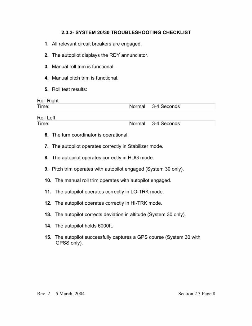
2.3.2- SYSTEM 20/30 TROUBLESHOOTING CHECKLIST
1. All relevant circuit breakers are engaged. � 2. The autopilot displays the RDY annunciator. � 3. Manual roll trim is functional. � 4. Manual pitch trim is functional. � 5. Roll test results:
Roll Right Time: Normal: 3-4 Seconds Roll Left Time: Normal: 3-4 Seconds
6. The turn coordinator is operational. � 7. The autopilot operates correctly in Stabilizer mode. � 8. The autopilot operates correctly in HDG mode. � 9. Pitch trim operates with autopilot engaged (System 30 only). � 10. The manual roll trim operates with autopilot engaged. � 11. The autopilot operates correctly in LO-TRK mode. � 12. The autopilot operates correctly in HI-TRK mode. � 13. The autopilot corrects deviation in altitude (System 30 only). � 14. The autopilot holds 6000ft. � 15. The autopilot successfully captures a GPS course (System 30 with
GPSS only). �

Rev. 2 5 March, 2004 Section 2.3 Page 9
2.3.3- VERTICAL HOLD FAILURE (System 30 only)
Symptom: The autopilot cannot hold an altitude (does not porpoise). Possible Causes:
1. The autopilot pitch trim relay is faulty.
What to do:
• Refer to line 9 of the pretest checklist. If checked, this
indicates a faulty autopilot pitch trim relay.
2. The pitch servo is faulty (pitch trim motor for SR20).
What to do: • Determine the functionality of the autopilot pitch trim relay.
Refer to line 9 of the pretest checklist.
• Refer to line 4 of the System 20/30 troubleshooting checklist. If unchecked, this indicates a faulty pitch trim motor (SR20 only).
• Refer to line 13 of the System 20/30 troubleshooting checklist.
If unchecked, and the pitch trim relay is operational, this indicates a faulty pitch trim servo (SR22 only).
3. The wiring between the autopilot and the pitch trim motor/servo assembly
is damaged. What to do:
• Ring the wiring between the autopilot and the roll trim motor/servo assembly. Refer to chapter 22 in the SR20/22 Wiring Manual.
Refer to Section 22-10 or 22-11 of the SR20/22 maintenance manual for details on the autopilot pitch
control system.

Rev. 2 5 March, 2004 Section 2.3 Page 10
4. The autopilot pitch computer is faulty, or the altitude transducer is inoperable.
What to do:
• If both the pitch servo and pitch relay are functional, this may
indicate a faulty altitude transducer, or a malfunctioning autopilot computer.
Symptom: The aircraft porpoises while in altitude hold mode. Possible Causes:
1. The altitude transducer is inoperable. What to do:
• Experience has shown that the transducer may be the most probable cause. It is recommended that this part be replaced first.
2. Water is present in the pitot static system.
What to do:
• Refer to chapter 34 in the SR20/22 AMM for instructions on determining proper pitot static system operation.
3. The pitch trim cartridge requires service.
What to do:
• Access the pitch trim cartridge (Refer to section 27-30 of the SR20/22 AMM).
• If movement of the piston is rough or sticky, replace or service
pitch trim cartridge. (Refer to section 27-30 of the SR20/22 AMM).
4. The elevator rigging system may be out of adjustment.

Rev. 2 5 March, 2004 Section 2.3 Page 11
What to do:
• Refer to section 27-30 in the SR20/22 AMM to verify proper rigging.
5. The wiring between the autopilot and the pitch trim motor/servo assembly
is damaged. What to do:
• Ring the wiring between the autopilot and the roll trim motor/servo assembly. Refer to chapter 22 in the SR20/22 Wiring Manual.
6. The autopilot pitch computer is faulty. What to do:
• Replace the system 30 autopilot pitch computer.
7. The autopilot pitch servo starting voltage is too high (above 2.5V). What to do:
• Gain access to and remove the autopilot pitch trim servo. (Refer to section 22-11 of the SR22 AMM).
• Using a variable voltage power supply, apply a voltage of 0
volts between pins 3 and 4 of J561 (connected to the servo).
• Slowly increase the voltage until the motor starts to turn. If this voltage is above 2.5V, this indicates a faulty autopilot pitch trim servo. Note: With a voltage applied to pins 3 and 4, only the motor within the servo will activate. The pulley attached to the servo will not move.
8. The pitch trim motor starting voltage is too high (above 2.5V).
What to do:
Omit this section for SR20.
Omit this section for the SR22.

Rev. 2 5 March, 2004 Section 2.3 Page 12
• Gain access to and remove the pitch trim motor. (Refer to section 27-30 of the SR20 AMM).
• Using a variable voltage power supply, apply a voltage of 0
volts between pins 1 and 2 of J634 (attached to pitch trim motor).
• Slowly increase the voltage until the motor starts to turn. If this voltage is above 2.5V, this indicates a faulty pitch trim motor.
2.3.4- ROLL CONTROL
Symptom: The autopilot oscillates while rolling. Possible Causes:
1. The roll trim tab needs to be adjusted. What to do:
• Refer to the pretest checklist. Specifically, compare line 5 table values to their normal values.
• If the measured values differ from the normal values, this
indicates a need for roll tab adjustment.
2. The roll trim cartridge requires service. What to do:
• Gain access to the roll trim cartridge (Refer to section 27-10 of the SR20/22 AMM).
• If movement of the piston is rough or sticky, replace or service
roll trim cartridge.
Refer to Section 27-10, page 15 in the SR20 AMM or page 21 in the SR22 AMM for details on roll trim
tabs.

Rev. 2 5 March, 2004 Section 2.3 Page 13
3. The aileron rigging system is out of adjustment. What to do:
• Refer to section 27-10 of the SR20/22 AMM to verify proper rigging.
4. The wiring between the autopilot and the roll trim motor assembly is
damaged. What to do:
• Ring the wiring between the autopilot and the roll trim motor assembly. Refer to chapter 22 in the SR20/22 Wiring Manual.
5. The Turn Coordinator/autopilot is faulty.
What to do:
• Refer to section 22-10 and 22-11 in the SR20/22 AMM. Check autopilot wire harnesses for damage or loose pins.
• Refer to line 6 of the pretest checklist. If unchecked, this may
indicate a faulty turn coordinator/autopilot computer.
Symptom: The autopilot always rolls right/left. Possible Causes:
1. The roll trim motor assembly is inoperable.
What to do:
• Refer to line 3 of the pretest checklist. If the manual trim is not in operation, then there is a problem with the roll trim motor assembly.
2. The wiring between the autopilot and the roll trim motor assembly is
damaged. What to do:

Rev. 2 5 March, 2004 Section 2.3 Page 14
• Ring the wiring between the autopilot and the roll trim motor
assembly. Refer to chapter 22 in the SR20/22 Wiring Manual.
3. The System 20/30 roll computer is faulty. What to do:
• Refer to section 22-10 and 22-11 in the SR20/22 AMM. Check autopilot wire harnesses for damage or loose pins.
• Refer to line 6 of the pretest checklist. If unchecked, this may
indicate a faulty turn coordinator/autopilot computer.
Symptom: The autopilot will not roll. Possible Causes:
1. The autopilot roll relay is inoperable.
What to do:
• Refer to line 9 of the pretest checklist. If the manual trim is functional while the autopilot is engaged, this indicates a faulty autopilot roll relay.
2. The roll trim motor is inoperable.
What to do:
• Perform the tests above to determine the condition of the
autopilot roll relay and turn coordinator. • Refer to line 3 of the pretest checklist. If the manual trim is not
in operation, the roll trim motor assembly is faulty.
3. The wiring between the autopilot and the roll trim motor assembly is damaged.
What to do:

Rev. 2 5 March, 2004 Section 2.3 Page 15
• Ring the wiring between the autopilot and the roll trim motor assembly. Refer to chapter 22 in the SR20/22 Wiring Manual.
4. The System 20/30 roll computer is faulty.
What to do:
• Refer to section 22-10 and 22-11 in the SR20/22 AMM. Check autopilot wire harnesses for damage or loose pins.
• Refer to line 6 of the pretest checklist. If unchecked, this may
indicate a faulty turn coordinator/autopilot computer.

Rev. 2 5 March, 2004 Section 2.3 Page 16
2.3.5- TRACKING Note: The S-Tec System 20/30 does not have the capability to intercept a course. It is the pilot’s responsibility to acquire a desired course.
Symptom: The autopilot cannot track a NAV course. Possible Causes:
1. The Garmin GNS430 or the Sandel ESHI (if installed) is not configured
correctly.
What to do:
• Ensure that the setup procedures at the beginning of this chapter are completed for the GNS430.
• If a Sandel EHSI is installed, ensure that the setup procedures
at the beginning of this chapter are completed for the Sandel.
2. The wiring between the System 20/30 and navigational instrumentation requires service.
What to do:
• Check the wire harnesses on the back of the System 20/30 autopilot. Ensure they are secure and free of damage.
• Ring out the wiring between the System 20/30 and the Garmin
GNS430. Where applicable, ring out the wiring between the System 20/30 and the HSI. Refer to the SR20/SR22 Wiring Manual, chapter 22 for wiring schematics.
3. The aircraft does not roll correctly.
What to do:
• Refer to the previous section regarding autopilot roll problems
for instructions.
4. The System 20/30 autopilot computer is faulty.

Rev. 2 5 March, 2004 Section 2.3 Page 17
What to do:
• Refer to section 22-10 and 22-11 in the SR20/22 AMM. Check autopilot wire harnesses for damage or loose pins.
• Refer to line 6 of the pretest checklist. If unchecked, this may
indicate a faulty turn coordinator/autopilot roll computer. Symptom: The autopilot cannot hold an ILS course. Note: Due to the extreme sensitivity of ILS tracking, harsh weather conditions may affect the aircraft's ability to hold an ILS approach accurately. The following procedures should be followed only if the aircraft is a large margin off the ILS course. Possible Causes:
1. The Sandel EHSI(if installed)/Garmin GNS430 is not set up correctly.
What to do:
• Ensure that the Sandel is configured correctly (if installed), according to the information in the setup guide at the beginning of this chapter.
• Ensure that the GNS430 is configured correctly, according to
the information in the setup guide at the beginning of this chapter.
2. The aircraft does not roll correctly.
What to do:
• Refer to the previous section regarding autopilot roll problems
for instructions.
3. The wiring between the System 20/30 and navigational instrumentation requires service.

Rev. 2 5 March, 2004 Section 2.3 Page 18
What to do:
• Check the wire harnesses on the back of the System 20/30 autopilot. Ensure they are secure and free of damage.
• Ring out the wiring between the System 20/30 and the Garmin
GNS430. Where applicable, ring out the wiring between the System 20/30 and the HSI. Refer to the SR20/SR22 Wiring Manual, chapter 22 for wiring schematics.
4. The System 20/30 autopilot computer is faulty.
What to do:
• Refer to section 22-10 and 22-11 in the SR20/22 AMM.
Check autopilot wire harnesses for damage or loose pins.
• Refer to line 6 of the pretest checklist. If unchecked, this may indicate a faulty turn coordinator/autopilot roll computer.
Symptom: The autopilot cannot follow a heading. Possible Causes:
1. The Sandel EHSI (if installed) is not set up correctly.
What to do:
• Ensure that the setup procedures at the beginning of this chapter are followed.
2. The HSI/DG is not operating correctly.
What to do:
• Enable power to the aircraft. Engage the HSI/DG. Check for
flags or erroneous operation. If flags are found, or erroneous indication is shown, this indicates a HSI/DG not operating correctly.

Rev. 2 5 March, 2004 Section 2.3 Page 19
3. The wiring between the System 20/30 and navigational instrumentation requires service.
What to do:
• Check the wire harnesses on the back of the System 20/30 autopilot. Ensure they are secure and free of damage.
• Ring out the wiring between the System 20/30 and the Garmin
GNS430. Where applicable, ring out the wiring between the System 20/30 and the HSI. Refer to the SR20/SR22 Wiring Manual, chapter 22 for wiring schematics.
4. The System 20/30 autopilot computer is faulty.
What to do:
• Refer to section 22-10 and 22-11 in the SR20/22 AMM. Check autopilot wire harnesses for damage or loose pins.
• Refer to line 6 of the pretest checklist. If unchecked, this may
indicate a faulty turn coordinator/autopilot roll computer.
Symptom: The autopilot cannot track a GPS course. Possible Causes:
1. The Garmin GNS430 is not set to track a GPS course.
What to do:
• Ensure that the Garmin GNS430 is set to display GPS information on the Sandel HSI by pressing the CDI key on the GNS430. The display should read GPS, instead of VLOC.
2. The Sandel EHSI (if installed) or the Garmin GNS430 is not set up
correctly.
What to do:

Rev. 2 5 March, 2004 Section 2.3 Page 20
• Follow the setup procedures outlined at the beginning of this chapter for both the Sandel EHSI, and the Garmin GNS430.
3. The wiring between the System 20/30 and navigational instrumentation
requires service. What to do:
• Check the wire harnesses on the back of the System 20/30 autopilot. Ensure they are secure and free of damage.
• Ring out the wiring between the System 20/30 and the Garmin
GNS430. Where applicable, ring out the wiring between the System 20/30 and the HSI. Refer to the SR20/SR22 Wiring Manual, chapter 22 for wiring schematics.
4. The HSI/DG is not working correctly.
• Enable power to the aircraft. Engage the HSI/DG. Check for flags or erroneous operation. If flags are found, or erroneous indication is shown, this indicates a HSI/DG not operating correctly.
5. The Garmin GNS 430 is inoperable.
What to do:
• Contact technical support for troubleshooting instructions.
6. The System 20/30 autopilot computer is faulty.
What to do:
• Refer to section 22-10 and 22-11 in the SR20/22 AMM.
Check autopilot wire harnesses for damage or loose pins.
• Refer to line 6 of the pretest checklist. If unchecked, this may indicate a faulty turn coordinator/autopilot roll computer.

Rev. 2 5 March, 2004 Section 2.3 Page 21
2.3.6- MISCELLANEOUS
Symptom: Autopilot produces noise on COM1/COM2. Possible Causes:
1. The automatic squelch on the GNS430 may need to be adjusted.
What to do:
• To adjust the squelch on the GNS430, refer to the GNS430 Installation Manual, Garmin P/N 190-00140-02. NOTE: This procedure is recommended for Cirrus service centers only.
2. Excess copper tape exists around the pitch servo .
What to do:
• Locate the autopilot pitch trim servo. Refer to chapter 27 of
the SR22 AMM.
• Inspect the pitch trim servo for excess copper tape, and remove any excess.
3. The pitch trim servo/motor needs to be replaced.
What to do:
• Locate the pitch trim servo/motor.
• Replace the pitch trim servo/motor, following procedures
outlined in chapter 27 of the SR20/22 Maintenance Manual.
4. The roll trim motor needs to be replaced.
• Replace the roll trim motor, following procedures outlined in chapter 27 of the SR20/22 Maintenance Manual.
Omit this section for SR20 aircraft.