ccps guidelines for initiating events and ......2/17/2016 1 ccps guidelines for initiating events...
TRANSCRIPT
2/17/2016
1
CCPS GUIDELINES FOR INITIATING EVENTS AND INDEPENDENT PROTECTION LAYERS IN LAYER OF PROTECTION ANALYSIS
AN OVERVIEWPART 1
SCOPE (OF THE BOOK)
CHANGES SINCE CCPS LOPA (2001)
INDEPENDENT PROTECTION LAYERS (IPL)
IPL CORE ATTRIBUTES/CHARACTERISTICS
DETAILED IPL INFORMATION
AGENDA

2/17/2016
2
SCOPE
NOT a 2nd Edition on CCPS LOPA (2001)
Provide EXAMPLES of IEs and IPLs and useful GUIDANCE
Detailed IE and IPL Information
Pressure Relief System Use and Treatment
IPLs and Time Dependency BPCS Credit Claims
CHANGES SINCE INITIAL LOPA CONCEPT BOOK

2/17/2016
3
INDEPENDENT PROTECTION LAYERS (IPLs)
A device, system or action capable of PREVENTING a scenario from proceeding to an undesired consequence regardless of the initiating event or the action of any other protection layer associated with the scenario
PROTECTION LAYERS (PLs)Source: www.exida.com

2/17/2016
4
SAFEGUARDS NOT TYPICALLY CREDITED AS IPLsSource: www.exida.com
TRAINING, CERTIFICATION AND PROCEDURES
TESTING INSPECTION AND MAINTENANCE
COMMUNICATIONS AND SIGNS
FIRE PROTECTION
IPL CORE ATTRIBUTES
INDEPENDENCE
FUNCTIONALITY
INTEGRITY
RELIABILITY
AUDITABILITY
ACCESS SECURITY
MANAGEMENT OF CHANGE (MOC)

2/17/2016
5
INDEPENDENCE
When the effective performance of one component is dependent upon the successful operation of another, the devices are NOT INDEPENDENT.
EXAMPLE: LV1 MALFUNCTIONS OPEN
INDEPENDENCE

2/17/2016
6
+
EXAMPLE: INSULATION AND PRV
INDEPENDENCE
INDEPENDENCE
EXAMPLE: REVERSE FLOW

2/17/2016
7
INDEPENDENCE - COMMON MODE FAILURE
EXAMPLE: CROSS/SAME TAP
EXAMPLE: LOSS OF POWER
INDEPENDENCE - COMMON MODE FAILURESource: CCPS Layer of Protection Analysis, Simplified Process Risk Assessment

2/17/2016
8
FUNCTIONALITY
An IPL needs to FUNCTION in a way that prevents or mitigates the consequence of the scenario being studied.
FUNCTIONALITY
EXAMPLE: RELIEF VALVE SPEC

2/17/2016
9
FUNCTIONALITY
EXAMPLE: BLAST WALL/EXPLOSION PROOFING
FUNCTIONALITY – TIME DEPENDENCY
PROCESS SAFETY TIME (PST)
The TIME PERIOD between a failure occurring in the process or its control system and the occurrence of the hazardous event

2/17/2016
10
FUNCTIONALITY – TIME DEPENDENCY
FUNCTIONALITY – TIME DEPENDENCY
T-400 T-400PSTLC LC
EXAMPLE: LIQUID OVERFILL
2/17/2016
11
FUNCTIONALITY – TIME DEPENDENCY
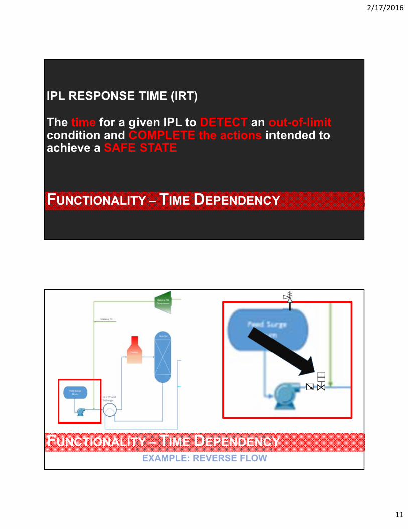
IPL RESPONSE TIME (IRT)
The time for a given IPL to DETECT an out-of-limitcondition and COMPLETE the actions intended to achieve a SAFE STATE
EXAMPLE: REVERSE FLOW
FUNCTIONALITY – TIME DEPENDENCY

2/17/2016
12
FUNCTIONALITY – TIME DEPENDENCY
PROCESS LAG TIME (PLT)
The TIME it takes for a process to ACHIEVE or MAINTAIN a SAFE STATE.
FUNCTIONALITY – TIME DEPENDENCY

2/17/2016
13
FUNCTIONALITY – TIME DEPENDENCY
MAXIMUM SETPOINT (MSP)
“NEVER EXCEED, NEVER DEVIATE” setpoint
FUNCTIONALITY – TIME DEPENDENCYSource: CCPS Guidelines for Initiating Events and Independent Protection Layers for Layer of Protection Analysis
2/17/2016
14
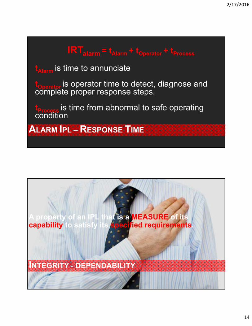
ALARM IPL – RESPONSE TIME
tAlarm is time to annunciate
tOperator is operator time to detect, diagnose and complete proper response steps.
tProcess is time from abnormal to safe operating condition
IRTalarm = tAlarm + tOperator + tProcess
INTEGRITY - DEPENDABILITY
A property of an IPL that is a MEASURE of its capability to satisfy its specified requirements.
2/17/2016
15
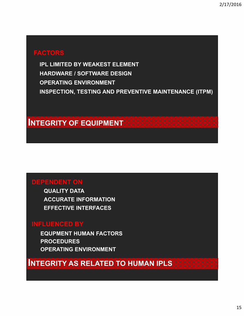
FACTORS
IPL LIMITED BY WEAKEST ELEMENT
HARDWARE / SOFTWARE DESIGN
OPERATING ENVIRONMENT
INSPECTION, TESTING AND PREVENTIVE MAINTENANCE (ITPM)
INTEGRITY OF EQUIPMENT
INTEGRITY AS RELATED TO HUMAN IPLS
QUALITY DATA
ACCURATE INFORMATION
EFFECTIVE INTERFACES
DEPENDENT ON
INFLUENCED BY
EQUPMENT HUMAN FACTORS
PROCEDURES
OPERATING ENVIRONMENT

2/17/2016
16
REVEALED FAILURE
INTEGRITY - DEPENDABILITY
UNREVEALED FAILURE
NOT A PART OF NORMAL OPERATION
TYPICAL FOR IPL
NOT AN INITIATING CAUSE
OBVIOUS
TYPICAL LOPA IC
LEAD TO PROCESS DEVIATION
RELIABILITY
An attribute of a protection layer related to its equipment OPERATING as intended, under stated conditions, for a specific time period.

2/17/2016
17
LOW DEMAND MODE
f1C is frequency of the consequence occurring for
scenario 1
IEF1 is frequency of IE for scenario 1
PFD1 is Probability of failure on demand of independent protection layer 1 for scenario 1
f1C = IEF1 x PFD1
LOW DEMAND MODE

2/17/2016
18
LOW DEMAND MODE
IEF1 = 0.1 demand/yr for human error or mechanical pump failure (typ)
PFD1 = 0.01/demand since the PSV is fully sized for the scenario and included in ITPM
f1C = 0.1 demand/yr x 0.01/demand
f1C = 0.001 event/yr
AUDITABILITY
inspect

2/17/2016
19
AUDITABILITY
AUDITABILITY – MAINTENANCE SYSTEMS

2/17/2016
20
AUDITABILITY – PROCEDURES & TRAINING
AUDITABILITY – MANAGEMENT OF CHANGE
CHANGES PROPERLY REVIEWED?
CHANGES PROPERLY DOCUMENTED?
ACTIONS ITEMS GENERATED COMPLETED?

2/17/2016
21
AUDITABILITY – LOPA APPROACH
PFDS UP-TO-DATE?
INITIATING EVENTS UP-TO-DATE?
ACCESS SECURITY
Includes the use of physical and/or administrative controls to reduce the CHANCES of unauthorized system changes which may impair a safety device.

2/17/2016
22
IPL CHARACTERISTICS
BIG ENOUGH?
STRONG ENOUGH?
FAST ENOUGH?
3 ENOUGHS
DETECT
DECIDE
DEFLECT
3 D’S
BIG “I” FOR INDEPENDENCE
ALL IPLS ARE SAFEGUARDS, BUT NOT ALL SAFEGUARDS ARE IPLS

2/17/2016
23
PASSIVE IPLS - DEFINITION
PASSIVE IPL
An IPL that does NOT require an action to be taken in order to achieve its function aimed at reducing risk.
PASSIVE IPLS - ASSUMPTION
ASSUMPTION
Passive IPLs are ONLY applicable if the consequence is defined in the ABSENCE of the IPL.

2/17/2016
24
Flame Arresters
Overflow Lines
Mechanical Stops
Secondary Containment Areas
Fire-resistant Insulation
Double-Walled Vessels
Blast-Resistant Buildings
Blast Wall
Passive IPL List
PASSIVE IPLS – FLAME ARRESTERS

2/17/2016
25
PASSIVE IPLS – FLAME ARRESTERS
END-OF-LINE DEFLAGRATION ARRESTER
PFD = 0.01OoM = 2
PASSIVE IPLS – FLAME ARRESTERS
END-OF-LINE DEFLAGRATION ARRESTER
Appropriate Location
Proper Orientation
Does not impose Flow Restrictions
Undergoes adequate ITPM (Inspection, Testing, and Preventive Maintenance)

2/17/2016
26
PASSIVE IPLS – FLAME ARRESTERS
IN-LINE DEFLAGRATION ARRESTER (WITHOUT TEMPERATUREMONITORING AND SHUTDOWN/ISOLATION)
PFD = 0.1OoM = 1
PASSIVE IPLS – FLAME ARRESTERS
IN-LINE DEFLAGRATION ARRESTER (WITH TEMPERATUREMONITORING AND SHUTDOWN/ISOLATION)
PFD = 0.01OoM = 2

2/17/2016
27
PASSIVE IPLS – FLAME ARRESTERS
IN-LINE DEFLAGRATION ARRESTER
Piping between ignition source and arrester is less than the run-up distance required to sustain DDT
Proper Orientation
Does not impose Flow Restrictions
Temperature monitoring at the hot side
Undergoes adequate ITPM (per Manufacturer’s recommendations)
PASSIVE IPLS – FLAME ARRESTERS
IN-LINE STABLE DETONATION ARRESTER (WITHOUTTEMPERATURE MONITORING AND SHUTDOWN/ISOLATION)
PFD = 0.1OoM = 1

2/17/2016
28
PASSIVE IPLS – FLAME ARRESTERS
IN-LINE STABLE DETONATION ARRESTER (WITHTEMPERATURE MONITORING AND SHUTDOWN/ISOLATION)
PFD = 0.01OoM = 2
PASSIVE IPLS – FLAME ARRESTERS
IN-LINE STABLE DETONATION ARRESTER
Appropriate Location
Proper Orientation
Does not impose Flow Restrictions
Temperature monitoring at the hot side
Undergoes adequate ITPM (per Manufacturer’s recommendations)

2/17/2016
29
PASSIVE IPLS – FLAME ARRESTERS
UNSTABLE (OVERDRIVEN) DETONATION ARRESTER (WITHOUTTEMPERATURE MONITORING AND SHUTDOWN/ISOLATION)
PFD = 0.01OoM = 2
PASSIVE IPLS – FLAME ARRESTERS
UNSTABLE (OVERDRIVEN) DETONATION ARRESTER (WITHTEMPERATURE MONITORING AND SHUTDOWN/ISOLATION)
PFD = 0.001OoM = 3

2/17/2016
30
PASSIVE IPLS – FLAME ARRESTERS
UNSTABLE (OVERDRIVEN) DETONATION ARRESTER
Appropriate Location
Proper Orientation (Horizontal / Vertical)
Does not impose Flow Restrictions
Temperature monitoring at the hot side
Undergoes adequate ITPM (per Manufacturer’s recommendations)
PASSIVE IPLS – OVERFLOW LINES
OVERFLOW LINE W/O FLOW IMPEDIMENTS
PFD = 0.001OoM = 3

2/17/2016
31
PASSIVE IPLS – OVERFLOW LINES
OVERFLOW LINE W/O FLOW IMPEDIMENTS
Clean Service (No Fouling/Plugging)
Ease of Accessibility for ITPM
Vertical rise does not impose hydraulic/dynamic head/pressure greater than the vessel MAWP
Undergoes adequate ITPM (per Manufacturer’s recommendations)
PASSIVE IPLS – OVERFLOW LINES
OVERFLOW LINE W/ PASSIVE FLUID OR RUPTURE DISK
PFD = 0.01OoM = 2

2/17/2016
32
PASSIVE IPLS – OVERFLOW LINES
OVERFLOW LINE W/ PASSIVE FLUID OR RUPTURE DISK
Clean Service (No Fouling/Plugging)
Ease of Accessibility for ITPM
Vertical rise does not impose hydraulic/dynamic head/pressure greater than the vessel MAWP
Rupture disk pressure setpoint is less than the vessel MAWP
Undergoes adequate ITPM (per Manufacturer’s recommendations)
PASSIVE IPLS – OVERFLOW LINES
OVERFLOW LINE W/ FLUID WITH POTENTIAL TO FREEZE
PFD = 0.1OoM = 1

2/17/2016
33
PASSIVE IPLS – OVERFLOW LINES
OVERFLOW LINE W/ FLUID WITH POTENTIAL TO FREEZE
Clean Service (No Fouling/Plugging)
Ease of Accessibility for ITPM
Vertical rise does not impose hydraulic/dynamic head/pressure greater than the vessel MAWP
Fluid seal is equipped with freeze-prevention mechanisms
Undergoes adequate ITPM (per Manufacturer’s recommendations)
PASSIVE IPLS – SECONDARY CONTAINMENT
DIKES, BERMS, AND BUNDS
PFD = 0.01OoM = 2
2/17/2016
34
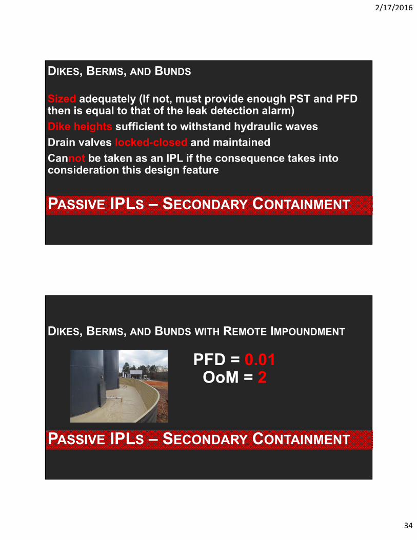
PASSIVE IPLS – SECONDARY CONTAINMENT
DIKES, BERMS, AND BUNDS
Sized adequately (If not, must provide enough PST and PFD then is equal to that of the leak detection alarm)
Dike heights sufficient to withstand hydraulic waves
Drain valves locked-closed and maintained
Cannot be taken as an IPL if the consequence takes into consideration this design feature
PASSIVE IPLS – SECONDARY CONTAINMENT
DIKES, BERMS, AND BUNDS WITH REMOTE IMPOUNDMENT
PFD = 0.01OoM = 2
2/17/2016
35
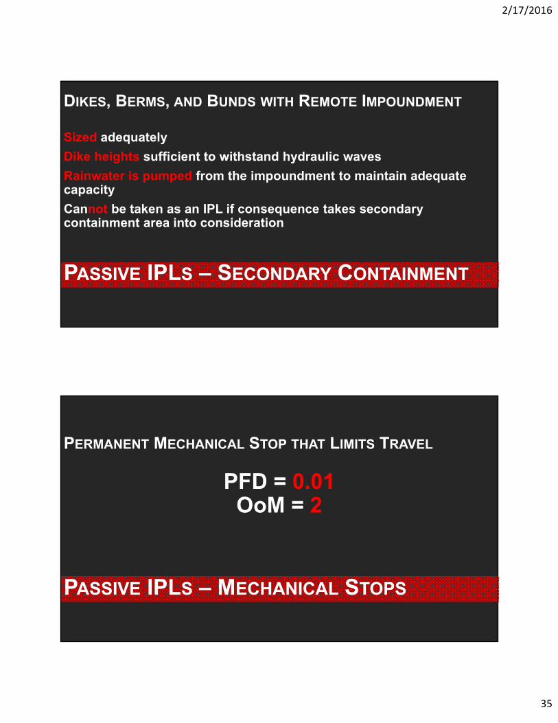
PASSIVE IPLS – SECONDARY CONTAINMENT
DIKES, BERMS, AND BUNDS WITH REMOTE IMPOUNDMENT
Sized adequately
Dike heights sufficient to withstand hydraulic waves
Rainwater is pumped from the impoundment to maintain adequate capacity
Cannot be taken as an IPL if consequence takes secondary containment area into consideration
PASSIVE IPLS – MECHANICAL STOPS
PERMANENT MECHANICAL STOP THAT LIMITS TRAVEL
PFD = 0.01OoM = 2

2/17/2016
36
PASSIVE IPLS – MECHANICAL STOPS
PERMANENT MECHANICAL STOP THAT LIMITS TRAVEL
No Potential for slippage (stop is welded)
Undergoes visual inspection for corrosion/wear
Documentation of design basis to ensure retention during MOC
PASSIVE IPLS – INSULATION/CLADDING
FIRE-RESISTANT INSULATION & CLADDING ON VESSEL
PFD = 0.01OoM = 2

2/17/2016
37
PASSIVE IPLS – INSULATION/CLADDING
FIRE-RESISTANT INSULATION & CLADDING ON VESSEL
Heat-up time must be greater than the length of fire
Must be independent of other IPLs such as PSVs
Undergoes periodic mechanical/civil inspections
PASSIVE IPLS – DOUBLE-WALLED SYSTEMS
DOUBLE-WALLED SYSTEMS
The PFD of a Double-Walled System is based on the PFD associated with the leak detection alarm IPL
alerting personnel of the loss of primary containment scenario.

2/17/2016
38
PASSIVE IPLS – CONTAINMENT BUILDINGS
CONTAINMENT BUILDINGS
Although containment buildings can reduce the risk for those outside the building, they can increase the
risk for those working inside the building.
PASSIVE IPLS – BLAST-RESISTANT STRUCTURES
BLAST-RESISTANT BUILDING DESIGNS & BLAST (SACRIFICIALWALLS) OR EXPLOSION BARRIERS
Common assumption: All people inside a well-maintained, blast-resistant enclosure that is properly designed for the maximum anticipated blast loading
are fully protected.

2/17/2016
39
QUESTIONS/COMMENTS?
MICHAEL SAURASENIOR ENGINEER/LOPA FACILITATORRISK MANAGEMENT PROFESSIONALS
(949) 282-0123 EXT. [email protected]
TIMOTHY LEEPROJECT ENGINEER
RISK MANAGEMENT PROFESSIONALS(949) 282-0123 EXT. [email protected]