blimpage general-purpose controller blimpage team: joseph brannan philip grippi daniel mccabe nguyen...
Post on 21-Dec-2015
214 views
TRANSCRIPT
BlimpageGeneral-Purpose Controller
Blimpage Team:
Joseph Brannan
Philip Grippi
Daniel McCabe
Nguyen Trinh
David Wolpoff
PreliminaryDesignReview

Modular general-purpose drone controller
Navigation, collision-detection, general motor interfaces, data collection
Zero-impact on system performance Lightweight, independently powered
What is The Blimpage
Blimpage
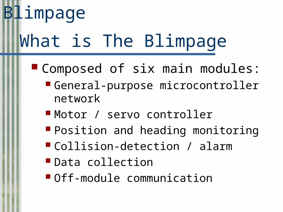
Composed of six main modules: General-purpose microcontroller
network Motor / servo controller Position and heading monitoring Collision-detection / alarm Data collection Off-module communication
What is The Blimpage
Blimpage
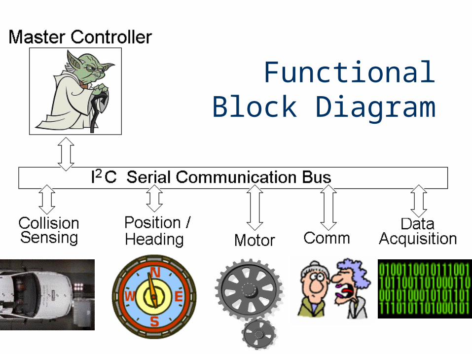
Functional Block Diagram
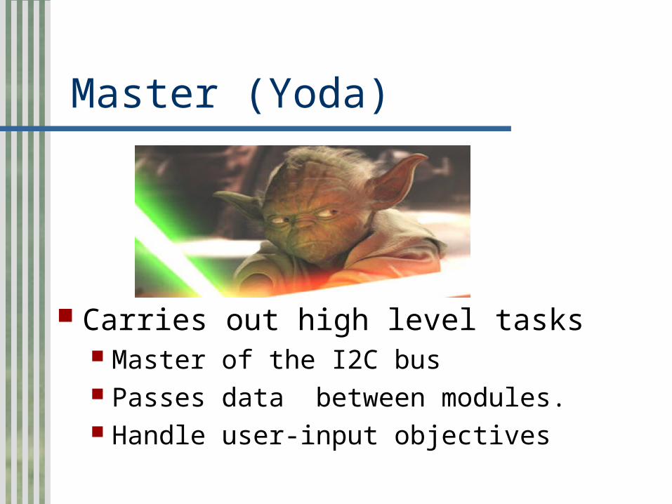
Master (Yoda)
Carries out high level tasks Master of the I2C bus Passes data between modules. Handle user-input objectives

Collision Detection
Collision uC slave cycles through 6 channels on Mux/Demux
Vcc multiplexed to 6 peripheral IR collision sensor’s (limit power)
outputs of sensors de-multiplexed into low pass filter
Low pass filter output sampled by uC ADC10
Collision status register visible to master controller updated continuously

Collision Detection
Collision uC Slave
Collision Sensor (x6)
>--------
----------
<-------
------
>----
----------------
|
|
|
|---Vcc
||
^ || |
|
^^
|
|
-----------------------
||
-<
---
LP Filter
Mux/Demux
-<|
<--------
----
output
power
Channel select
|||
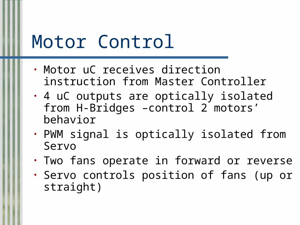
Motor Control• Motor uC receives direction instruction
from Master Controller• 4 uC outputs are optically isolated from H-
Bridges –control 2 motors’ behavior• PWM signal is optically isolated from
Servo• Two fans operate in forward or reverse• Servo controls position of fans (up or
straight)

Motor Control
Motor uC x2 H-Bridge Motor Drivers
Micro Servo
-------- -----
----------
x4 optical isolators
optical isolator
|
|
|PWM signal
-----
----------
----|||
-------------------------
||
||
<---
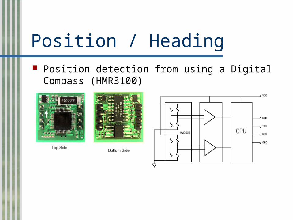
Position / Heading Position detection from using a Digital Compass
(HMR3100)
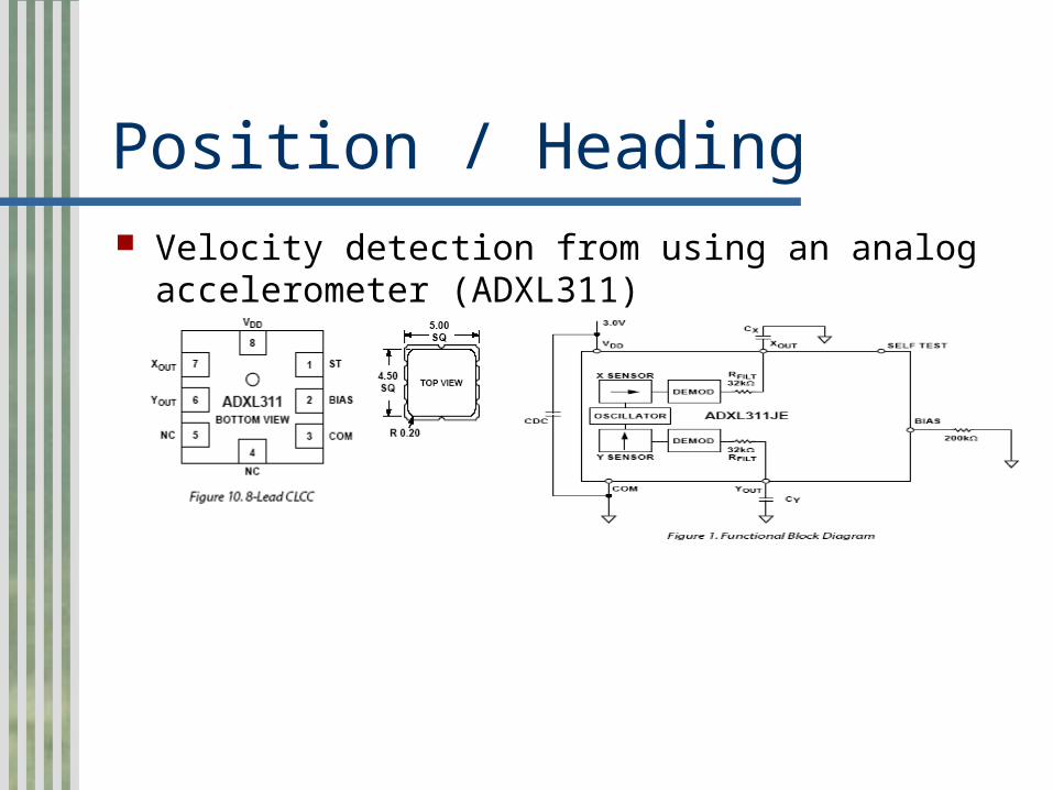
Position / Heading Velocity detection from using an analog
accelerometer (ADXL311)
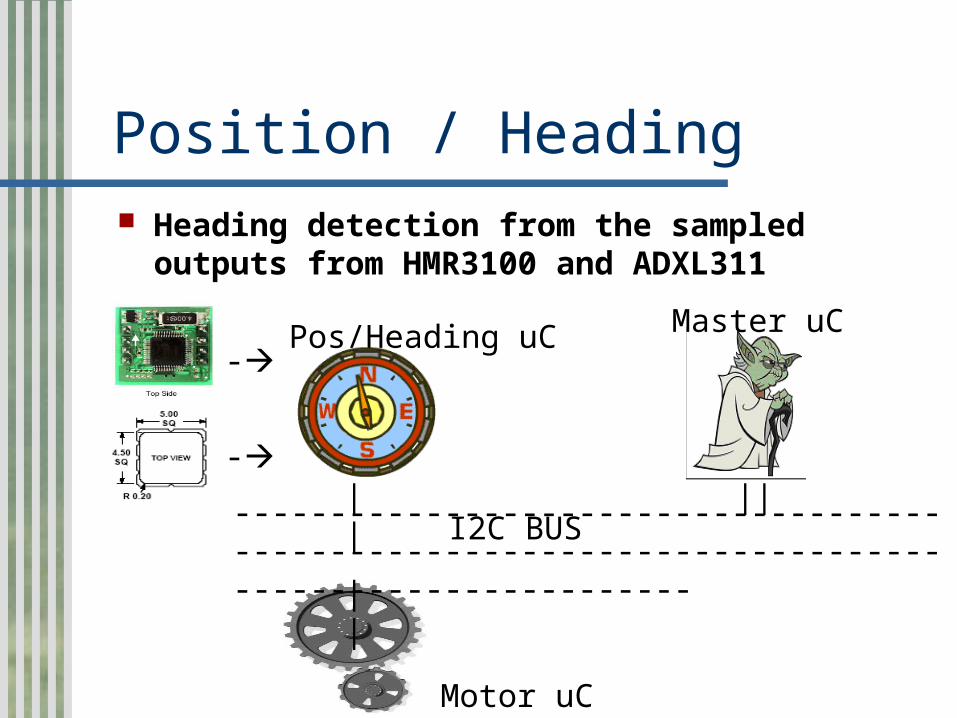
Position / Heading Heading detection from the sampled
outputs from HMR3100 and ADXL311
-
-
Pos/Heading uC
--------------------------------------------------------------------------------------------------
I2C BUS||
||
||
Motor uC
Master uC

Communications “Standard” RS-232 serial
communication. Connects to a host utilizing a
MAX3232 interface. All necessary components are kept
with the host to reduce weight.
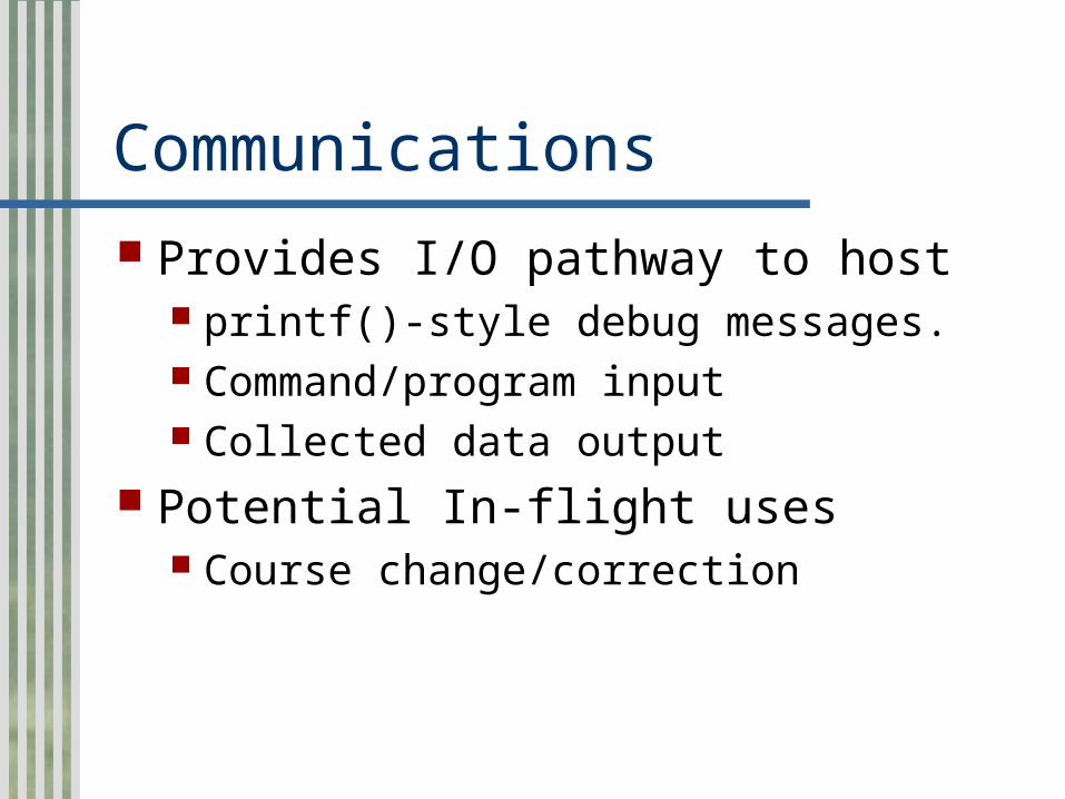
Communications Provides I/O pathway to host
printf()-style debug messages. Command/program input Collected data output
Potential In-flight uses Course change/correction

Data Acquisition Control sensors for collecting data
Audio or Image data Store data for later transmission or
retrieval Do nothing until a “target” waypoint Dropping eggs on Tom from 30’ IS
data acquisition.

Data Acquisition Possible data collection sources
JamCam or other RS232 enabled camera.
ISD1200 voice record chip Analog sampling to external RAM chip Mechanically actuated egg dropping
device. ;-)
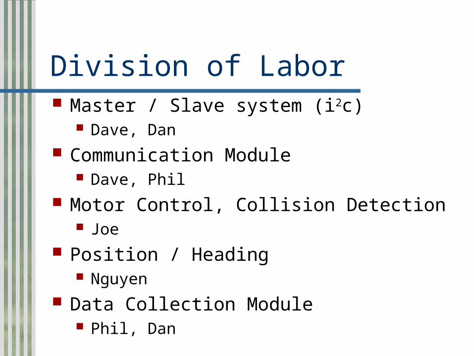
Division of Labor Master / Slave system (i2c)
Dave, Dan Communication Module
Dave, Phil Motor Control, Collision Detection
Joe Position / Heading
Nguyen Data Collection Module
Phil, Dan

Division of Labor Group Tasks
Documentation
PCB Population
Systems Integration
Review and Testing

Project TimelineBlimpage
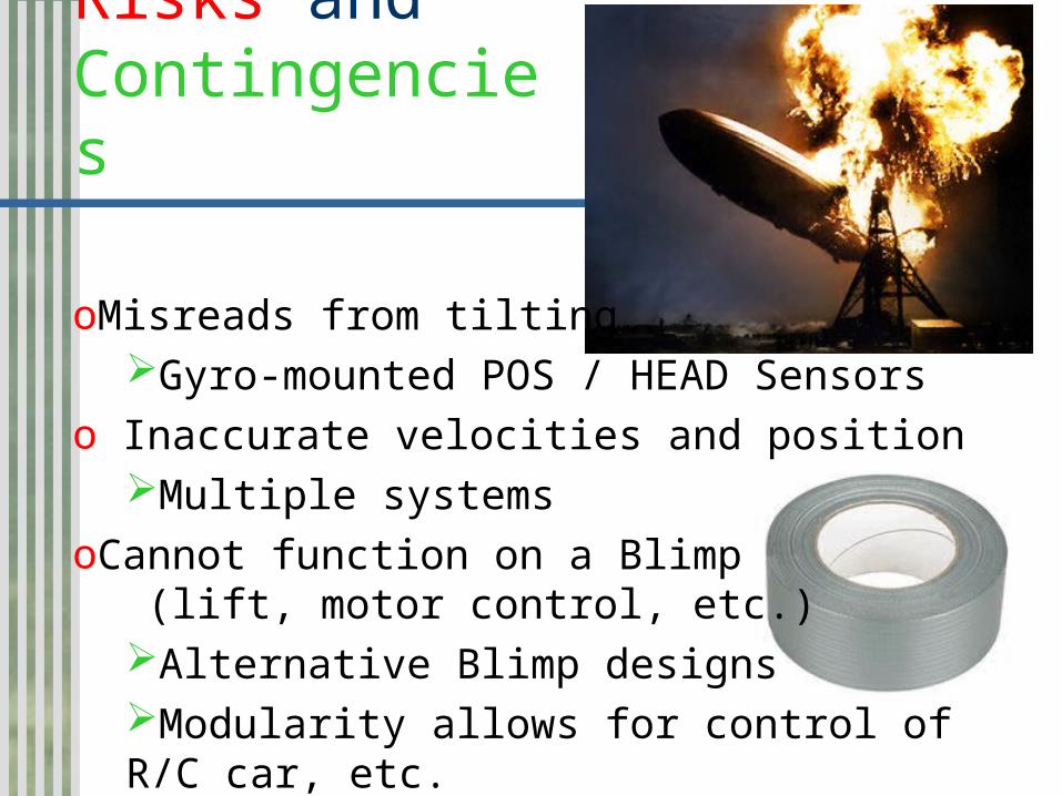
Risks and Contingencies
oMisreads from tiltingGyro-mounted POS / HEAD Sensors
o Inaccurate velocities and positionMultiple systems
oCannot function on a Blimp (lift, motor control, etc.)
Alternative Blimp designsModularity allows for control of R/C car, etc.
Blimpage ANY QUESTIONS??