basics of surveying ii
TRANSCRIPT

7/27/2019 Basics of Surveying ii
http://slidepdf.com/reader/full/basics-of-surveying-ii 1/48
SURVEYING
PreambleSurveying is involved in a project from conceptual
stage to construction and afterwards in
maintenance also. Depending on the stage at which
surveying is carried out it can be called.
i) Pre construction
survey
Feasibility survey (RECT, PECT)
ii) Constructionsurvey
To maintain alignment and Geometrycontrol during construction. (FLS
and other )
iii) Post
construction
Maintenance survey
7/27/2019 Basics of Surveying ii
http://slidepdf.com/reader/full/basics-of-surveying-ii 2/48
Definition : Operation of making such
measurements that the relative position of various features, natural or Artificial on the
surface of the earth can be exhibited in their
correct Horizontal and vertical relationship.
Normally determining position in Horizontal
plane is called surveying.
Determining relative heights or depth is called
levelling.
7/27/2019 Basics of Surveying ii
http://slidepdf.com/reader/full/basics-of-surveying-ii 3/48
Purpose : The main object of surveying is the
preparation of maps or plans which are the basis in
planning and design of engineering project such asroute location of railway line, roads and water supply
scheme.
Basic Principles in Surveying : Ruling
principle of survey is :
i) “ to work from whole to part”. For surveying
Establish control points with high precision by use of
Triangulation and precise levelling. Area is furtherdivided into triangle, which are surveyed with less
accuracy.
ii) to fix the position of new stations by atleast two
independent processes – By linear and Angular
7/27/2019 Basics of Surveying ii
http://slidepdf.com/reader/full/basics-of-surveying-ii 4/48
Classification of Surveys : Surveying is divided into
two main categories-
i) Geodetic Surveyii) Plane survey
i) Geodetic Survey :- When survey extends over a
large areas more than 200 sq. km. and degree of
accuracy is also great. The curvature of earth is alsotaken into account. Geodetic survey is used to provide
control points to which small surveys can be connected.
ii) Plane Survey :- For small projects covering Area
less than 200 sq.km. Earth curvature is not counted for
in distances. Earth surface is considered as plane.
(Angular error of 1” in 200 sq. km. area by assuming
plane).

7/27/2019 Basics of Surveying ii
http://slidepdf.com/reader/full/basics-of-surveying-ii 5/48
A) Classification based upon equipment used:
i) Chain survey
ii) Compass survey
iii) Theodolite surveyiv) Plane Table survey
v) Tachometric survey
vi) Aerial Photographic Survey
vi) Remote sensing.B) Based upon Method Employed :
i) Triangulation : Control points are established
through a net-work of triangles.ii) Traversing: Scheme of control points
consisting of a series of connected lines.
iii) Trilateration: Distances are measured for
exercising the control.

7/27/2019 Basics of Surveying ii
http://slidepdf.com/reader/full/basics-of-surveying-ii 6/48
Leveling :
The art of determining relative altitudesof points on the surface of the earth of
beneath the surface of earth is called
LEVELLING.
For execution of Engineering Projects it is
very necessary to determine elevations of different points along the alignment of
proposed project.
7/27/2019 Basics of Surveying ii
http://slidepdf.com/reader/full/basics-of-surveying-ii 7/48
Other applications are :
i) Taking rail levels existing before track renewals to
finalize final rail level profile including vertical curves.
ii) Initial ground levels for earthwork calculations.
iii) Levels for measurement of earthwork.
iv) Measurement of ballast etc.
Terms used in Levelling –
a) DATUM – or Datum plane is an arbitrarily assumedlevel surface or line with reference to which level of
other line or surface are calculated.
7/27/2019 Basics of Surveying ii
http://slidepdf.com/reader/full/basics-of-surveying-ii 8/48
b) REDUCED LEVEL (RL) – Height or depth of a
point above or below the assumed datum is called
Reduced level.
c) BENCH MARK – (BM) – B.M. is a fixed reference
point of known elevation. It may be of the following
types.i) GTS Bench mark (Geodetic Triangulation Survey) :
These Bench marks are established by national
agency like Survey of India. They are established
with highest precision. Their position and elevationabove MSL is given in a special catalogue known as
GTS Maps ( 100 km. interval).
7/27/2019 Basics of Surveying ii
http://slidepdf.com/reader/full/basics-of-surveying-ii 9/48
ii)Permanent Bench Mark : They are fixed
points of reference establish with reference to GTS
Bench mark (10 km. interval).
iii) Arbitrary Bench mark : These are
reference points whose elevations are arbitrarilyassumed. In most of Engineering projects, the
difference in elevation is more important than their
reduced levels with reference to MSL as given in aspecial catalogue known as GTS Maps ( 100 Km.
interval).

7/27/2019 Basics of Surveying ii
http://slidepdf.com/reader/full/basics-of-surveying-ii 10/48
d)Mean Sea Level (M.S.L.) : M.S.L. is obtained by
making hourly observations of the tides at any place
over a period of 19 years. MSL adopted by Survey of India is now Bombay which was Karachi earlier.
e) Level Surface : The surface which is parallel tothe mean sphereoidal surface of the earth is known as
level surface.
f ) Line of Collimation : It is the line joining theintersection of the cross hair and the optical center of
the objective and its extensions, it is also called line of
sight or collimation.
7/27/2019 Basics of Surveying ii
http://slidepdf.com/reader/full/basics-of-surveying-ii 11/48
g) Height of Instrument (HI) : The elevation of the line
of sight with respect to assumed datum is known as HI.
h) Back sight : (B.S.) - The first sight taken on alevelling staff held at a point of known elevation. B.S.
enables the surveyor to obtain HI +sight i.e. Height of
Instrument or line of sight.
i) Fore Sight : (F.S.) – It is the last staff reading taken
from a setting of the level. It is also termed as minus
sight.
Fore sight is the sight taken on a levelling staff held ata point of unknown elevation to ascertain the amount
by which the point is above or below the line of sight.
This is also called minus sight as the foresight reading
is always subtracted from height of Instrument.

7/27/2019 Basics of Surveying ii
http://slidepdf.com/reader/full/basics-of-surveying-ii 12/48
k) Change Point (CP) : The point on which
both the foresight and back sight are takenduring the operation of levelling is called
change point.
l) Intermediate Sight (IS) :
The foresight taken on a levelling staff held
at a point between two turning points, todetermine the elevation of that point, is
known as intermediate sight.
7/27/2019 Basics of Surveying ii
http://slidepdf.com/reader/full/basics-of-surveying-ii 13/48
It may be noted that for one setting of a level, there
will be only one back sight and one foresight but there
can be any number of intermediate sights.Type of Leveling Equipments:i) Dumpy level
ii) Tilting level
iii) Automatic leveliv) Digital Auto level
Dumpy level : It is simple compact and stable. The
telescope is rigidly fixed to its support thereforecannot be rotated about its longitudinal axis. A long
bubble tube is attached to the top of telescope.
Dumpy literally means short and thick.
7/27/2019 Basics of Surveying ii
http://slidepdf.com/reader/full/basics-of-surveying-ii 14/48
Tilting level : It consists of a telescope
attached with a level tube which can be tilted
within few degrees in vertical plane by a tilting
screw.
The main peculiarity of this level is that thevertical axis need not be truly vertical, since the
line of collimation is not perpendicular to it. The
line of collimation, is, however, made horizontalfor each pointing of telescope by means of tilting
screw. It is mainly designed for precise levelling
work.

7/27/2019 Basics of Surveying ii
http://slidepdf.com/reader/full/basics-of-surveying-ii 15/48
The Automatic level : Also termed as self
aligning level. The fundamentaldifference between automatic and the
classic spirit level is that in the former
the line of sight is no longer levelled
manually using a tubular spirit level, but
is leveled automatically within a certain
tilt range. This is achieved by
compensator in the telescope.
7/27/2019 Basics of Surveying ii
http://slidepdf.com/reader/full/basics-of-surveying-ii 16/48
Advantage of automatic level
i) Much simpler to use
ii) High precision – Mean elevation error
on staff graduated to 5mm division varies
between +0.5 to 0.8 mm per km of forward
and backward leveling.
iii) High speed : For fly leveling the
progress achieved by various level-wise
compared.
7/27/2019 Basics of Surveying ii
http://slidepdf.com/reader/full/basics-of-surveying-ii 17/48
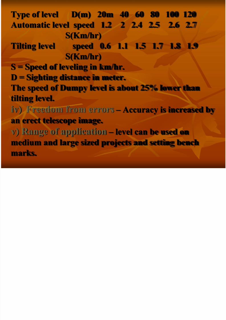
Type of level D(m) 20m 40 60 80 100 120
Automatic level speed 1.2 2 2.4 2.5 2.6 2.7
S(Km/hr)
Tilting level speed 0.6 1.1 1.5 1.7 1.8 1.9
S(Km/hr)
S = Speed of leveling in km/hr.
D = Sighting distance in meter.The speed of Dumpy level is about 25% lower than
tilting level.
iv) Freedom from errors – Accuracy is increased by
an erect telescope image.v) Range of application – level can be used on
medium and large sized projects and setting bench
marks.

7/27/2019 Basics of Surveying ii
http://slidepdf.com/reader/full/basics-of-surveying-ii 18/48
Basic components of level :
1. Telescope – to provide a line of sight
2. Level Tube – to make line of sight horizontal
3. Leveling head – to bring the bubble of tube level
at the centre of its run.
4. Tripod – to support the above three parts of thelevel.
1. TELESCOPE : Telescope is an optical
instrument used for magnifying and viewing the
images of distant objects. It consists of two lenses.
The lens fitted near the eye is called the eye piece and
the other fitted at the end near to the object is called
the objective lens.
7/27/2019 Basics of Surveying ii
http://slidepdf.com/reader/full/basics-of-surveying-ii 19/48
The objective provides a real inverted image in
front of the eye piece at a distance lesser than its
focal distance.
Two essential conditions are involved. :
i) The real image of the object, must be formed.Ii) the plane of image must coincide with that of
cross hairs.
Focusing of Telescope : The operation of obtaining a clear image of the object in the plane
of cross hairs is known as focusing.

7/27/2019 Basics of Surveying ii
http://slidepdf.com/reader/full/basics-of-surveying-ii 20/48
1. Diaphragm : A frame carrying cross hairs usually
made of either silk thread or platinum wire and placed at
the plane at which vertical image of the object is formed
by the objective.Vertical hair of the diaphragm enables the surveyor to
check the verticality of leveling staff whereas horizontal
hairs are used to read the staff graduations.
2.Level Tube : Also known as Bubble Tube consists of
a glass tube placed in a brass tube which is sealed with
plaster of Paris. The whole of the interior surface or the
upper half is accurately ground so that its longitudinalsection, is an arc of a circle. Level tube is filled with
either or alcohol, the remaining space is occupied by an
air bubble. The centre of air bubble always rest at the
highest point of the tube.
7/27/2019 Basics of Surveying ii
http://slidepdf.com/reader/full/basics-of-surveying-ii 21/48
Outer surface of the bubble tube is graduated
in both the directions from the centre.
The line tangential to the circular are at its
highest point i.e. the middle of tube is calledthe axis of bubble tube. When the bubble is
central the axis of bubble becomes Horizontal.
The level tube is attached on the top of
Telescope by means of capstan headed nuts.
7/27/2019 Basics of Surveying ii
http://slidepdf.com/reader/full/basics-of-surveying-ii 22/48
3.Leveling head : Leveling head generallyconsists of two parallel plates with 3 foot
screws. Upper plate is known as Tribrach and
lower plate is trivet which can be screwed on tothe tripod. Leveling head has to perform 3
distant functions :
i) to support the telescope
ii) to attach the level to the tripodiii) to provide a means for level (foot screws)
7/27/2019 Basics of Surveying ii
http://slidepdf.com/reader/full/basics-of-surveying-ii 23/48
Adjustment of level :
i) Temporarily Adjustments – adjustments whichare made for every setting of a level.
ii) Permanent adjustments- required if some error is
there in instrument.
i) Temporary Adjustments : includesa) setting up the level
b) leveling up
c) elimination of parallax
a) Setting up the level : This operation includes
fixing the instrument on the tripod and also
approximate levelling by leg adjustment.

7/27/2019 Basics of Surveying ii
http://slidepdf.com/reader/full/basics-of-surveying-ii 24/48
b) Leveling up : Accurate levelling is done with the
help of foot screws and by using plate levels. The object
of leveling up the instrument is to make its vertical axistruly vertical.
c) Elimination of parallax : If the image formed by
the objective does not lie in the plane of the cross hairs,there will be a shift in the image due to shift of the eye.
Such displacement of image is termed as parallax.
Parallax is removed in two stages.
1) Focusing the eye for distinct vision of cross hairs.
2) Focusing the objective so that image is formed in the
plane of cross hairs.
7/27/2019 Basics of Surveying ii
http://slidepdf.com/reader/full/basics-of-surveying-ii 25/48
Principles of leveling :
a) Simple leveling : The operation of levelling for determining the difference in
elevation, if not too great between two
points visible from single position of thelevel is known as simple levelling.
PROCEDURE : Following steps areinvolved.

7/27/2019 Basics of Surveying ii
http://slidepdf.com/reader/full/basics-of-surveying-ii 26/48
1.Level the instrument correctly.
2. Direct the telescope towards the staff held
3. Take the reading of Central, horizontal hair of the
diaphragm, where it appears to cut the staff ensuring
that the bubble is central.4. Send the staff to next point
5. Direct the telescope towards C and focus it again
6. Check up the bubble if central, if not bring it to the
Central position by the foot screw nearest to thetelescope.
7. Take the reading of Central Horizontal cross hair.

7/27/2019 Basics of Surveying ii
http://slidepdf.com/reader/full/basics-of-surveying-ii 27/48
b) Differential leveling or fly leveling :
This method is used in order to find the
difference in elevation between two points.
i) If they are too far apartii) if the difference in elevation between them is
too great.
iii) If there are obstacles intervening. In suchcase it is necessary to set up the level in several
positions and to work in series of stages.

7/27/2019 Basics of Surveying ii
http://slidepdf.com/reader/full/basics-of-surveying-ii 28/48
The difference of level of the points A&B is equalto the algebraic sum of these difference between
the sum of back sights and sum of the fore sights
i.e. Σ BS - Σ FS
Booking and reduction of the levels may be done
by following 2 methods.
i) Rise and fall methodii) Height of collimation method
7/27/2019 Basics of Surveying ii
http://slidepdf.com/reader/full/basics-of-surveying-ii 29/48
RISE AND FALL METHOD –
In this method, the difference of level between two
consecutive points for each setting of the instrument isobtained by comparing their staff readings.
The difference between their staff readings
indicates a rise if back sight is more than foresight and a
fall if it is less than foresight.The Rise and Fall worked out for all the points
given the vertical distances of each point relative to the
proceeding one.
If the RL of the Back staff point is known, then RL
of the following staff point may be obtained by adding its
rise or substracting fall from the RL of preceding point.

7/27/2019 Basics of Surveying ii
http://slidepdf.com/reader/full/basics-of-surveying-ii 30/48
Height of Collimation Method:
In this method Height of Instrument(H.I.) is calculated for each setting of the
instrument by adding the back sight (B.S.) to
the elevation of B.M.
Height of instrument (H.I.) = R.L. of the
plane of collimation= R.L. of B.M.+B.S.
7/27/2019 Basics of Surveying ii
http://slidepdf.com/reader/full/basics-of-surveying-ii 31/48
RL of a point = H.I. – FS
Or = H.I. – IS
- After every back sight, there may be many
intermediate sights but there must be only oneforesight.
- The B.S. & F.S. forms the two ends of one
stage in levelling.
- Levelling should always commence from a
permanent B.M. and end on a permanent B.M.

7/27/2019 Basics of Surveying ii
http://slidepdf.com/reader/full/basics-of-surveying-ii 32/48
THEODOLITE

7/27/2019 Basics of Surveying ii
http://slidepdf.com/reader/full/basics-of-surveying-ii 33/48
THEODOLITE - An instrument used for measuring
horizontal and vertical angles accurately is known
as theodolite.Uses of Theodolite
i) Measurement of Horizontal and vertical angles.
Ii) Setting out lines and angles
iii) Optical distance measurement
iv) Plumbing tall building
v) Setting out of Railway curves
vi) Locating the position of piers for Bridge etc.vii) Geographical position fixing from observation
of sun and stars.
viii) Alignment control in tunnel construction.
7/27/2019 Basics of Surveying ii
http://slidepdf.com/reader/full/basics-of-surveying-ii 34/48
Types of Theodolite : Transit theodolites are
categorized into 3 types :1. Vernier theodolite
2. Optical Reading Theodolite
3. Digital Theodolite/Electronic Theodolite
Basically Transit Theodolite are those in
which the telescope can revolve through acomplete revolution about its Horizontal axis
in vertical plane.

7/27/2019 Basics of Surveying ii
http://slidepdf.com/reader/full/basics-of-surveying-ii 35/48
Components of Transit theodolite –
Transit theodolite consists of the followingparts :
1. Leveling Head
2. Lower Plate or Scale Plate
3. Upper Plate or Vernier Plate
4. The standard or A Frame
5. T-Frame or Index Bar.
6. Plate Levels7. Telescope
7/27/2019 Basics of Surveying ii
http://slidepdf.com/reader/full/basics-of-surveying-ii 36/48
1.Leveling Head - Leveling Head consists of
upper tribrach and lower Tribrach. Upper
tribrach has three arms, each arm carries aleveling screw for leveling the equipment.
Lower tribrach has got a circular hole through
which a plumb bob may be suspended forcentering.
Three distinct functions of leveling head are:
i) to support the main part of the instrument
ii) to attach the Theodolite to the Tripod
iii) to provide a means for levelling the
theodolite
7/27/2019 Basics of Surveying ii
http://slidepdf.com/reader/full/basics-of-surveying-ii 37/48
2. Lower Plate (Scale Plate) : Lower Plate
which is attached to outer spindle, carries a
horizontal graduated circle, it is graduatedfrom 0-360. Each degree is further divided
into 10 minutes or 20 minutes. Scale plate can
be clamped to any position by a clampingscrew and a corresponding slow motion screw.
When the lower plate is tightened, the lower
plate is fixed to the upper tribrach of the
levelling head. The size of the Theodolite is
determined by the size of the diameter of this
lower plate.
7/27/2019 Basics of Surveying ii
http://slidepdf.com/reader/full/basics-of-surveying-ii 38/48
3.Upper plate or Vernier Plate : Upper
plate is attached to Inner spindle axis. Two venires
are screwed to the upper plats. It carries an upperclamp screw and tangent screw. On clamping the
upper clamp and unclamping the lower clamp, the
instrument may be rotated on its outer spindle
without any relative motion between the two plates.
On the other hand if lower clamp screw is
tightened and upper clamp screw is unclamped, the
instrument may be rotated about its inner spindlewith a relative motion between the vernier and
graduated scale of the lower plate. This property is
utilised for measuring angles.
4 Plate Levels - Upper plates carries two plate
7/27/2019 Basics of Surveying ii
http://slidepdf.com/reader/full/basics-of-surveying-ii 39/48
4. Plate Levels - Upper plates carries two plate levels placed at right angles to each other. One of the
plate bubble is kept parallel to the trunion axis. Plate
levels can be centered with the help of foot screws.
5. Telescope – Telescope is supported on the pivots
of the trunion axis which affords its movement in the
vertical plane.
IMPORTANT DEFINITIONS –
I) Line of Collimation - the line which passes
through the Intersection of the cross hairs of the eyepiece and optical centre of the objective and its
continuation is called as line of collimation. This is also
known as line of sight.

7/27/2019 Basics of Surveying ii
http://slidepdf.com/reader/full/basics-of-surveying-ii 40/48
ii)Transiting - The process of turning thetelescope in vertical plane through 180 deg.
about its horizontal axis is known as
transiting.
iii) Swing - A continuous motion of telescope
about the vertical axis in horizontal plane is
called swing. The swing may be in eitherdirection i.e. Right swing or left swing.
7/27/2019 Basics of Surveying ii
http://slidepdf.com/reader/full/basics-of-surveying-ii 41/48
iv) Face left observation – When vertical circle is on
the left of the telescope at the time of observation, the
observations are called face left observation.
v) Face right observation – When vertical circle is on
the right of the telescope at the time of observation.
TEMPORARY ADJUSTMENT OF
THEODOLITE
1) Setting up the Theodolite over the station2) Leveling up the theodolite
3) Elimination of the parallax
7/27/2019 Basics of Surveying ii
http://slidepdf.com/reader/full/basics-of-surveying-ii 42/48
1.Setting up : Operation of setting up a theodolite
includes:
a) centering the theodolite over the ground mark
b) approximate leveling with the help of tripod legs.
2. Leveling up of theodolite
The operation of making the vertical axis trulyvertical is known as levelling of Theodolite.
i) Turn the horizontal plate until the
longitudinal axis of the plate level is
approximately parallel to a line joining any two
levelling screws.
7/27/2019 Basics of Surveying ii
http://slidepdf.com/reader/full/basics-of-surveying-ii 43/48
ii) Bring the bubble to the centre of its run by turning
both foot screws simultaneously in opposite directions
either inwards or outwards. The movement of the left
thumb indicates the direction of movement of bubble.
iii) Turn the instrument through 1800 in azimuth.
iv) Note the position of the bubble. If it occupies a
different position, move it by means of the same two foot
screws to the approx. mean of the two positions.v) Turn
the theodolite through 90 in azimuth so that the platelevel becomes perpendicular to the previous position.
vi) With the help of third floor screw, move the bubble to
the approx. mean position already indicated.
7/27/2019 Basics of Surveying ii
http://slidepdf.com/reader/full/basics-of-surveying-ii 44/48
vii) Repeat the process until the bubble, retains
the same position for every setting of the
instrument.3. Elimination of Parallax : Elimination of parallax
may be done by focusing the eye piece for distinct vision
of cross hairs and focusing the objective to bring the
image of the object in the plane of cross hairs.
Measurement of Horizontal Angle
Procedure : to measure a Horizontal Angle
ABC between BA & BC the following
procedure is followed.

7/27/2019 Basics of Surveying ii
http://slidepdf.com/reader/full/basics-of-surveying-ii 45/48
1.Set up, Centre and level the theodolite over
the ground point B.
2. Loosen the upper plate, set the vernier to
read zero and clamp the upper clamp.
3. Loosen the lower plate and swing the
telescope until the left point A is sighted.
Tighten the lower clamp. Accurate bisection
of the arrow held on the Point A is done by
using the lower tangent screw. Read both the
vernier and take the mean of the reading.
7/27/2019 Basics of Surveying ii
http://slidepdf.com/reader/full/basics-of-surveying-ii 46/48
4. Unclamp the upper plate and swing the
telescope in clockwise direction until point C isbrought in the field of view. Tighten the upper
clamp and bisect the mark of C accurately,
using the upper clamp tangent screw.
5. Read both the verniers and take the mean
of readings. The difference of the means of thereading to C to A is the required angle ABC.

7/27/2019 Basics of Surveying ii
http://slidepdf.com/reader/full/basics-of-surveying-ii 47/48
6. Change the face of the instrument
and repeat the show procedure, the
measure of the angle is again obtained
by taking the difference of the means of
the readings to C&A on face right.
7. The mean of the two measures of the
angle ABC on two faces is the required
value of the angle ABC.

7/27/2019 Basics of Surveying ii
http://slidepdf.com/reader/full/basics-of-surveying-ii 48/48
THANKS