engineering surveying-ii
TRANSCRIPT
Prof. Dr.-Ing. John Bosco Kyalo KiemaUniversity of Nairobi
Email: [email protected]
by
Engineering Surveying II
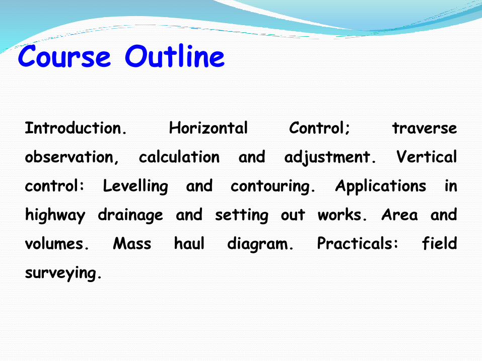
Course Outline
Introduction. Horizontal Control; traverse
observation, calculation and adjustment. Vertical
control: Levelling and contouring. Applications in
highway drainage and setting out works. Area and
volumes. Mass haul diagram. Practicals: field
surveying.
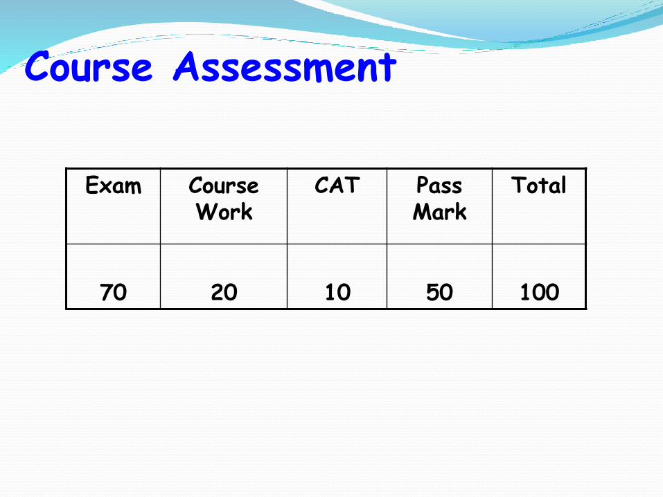
Exam Course Work
CAT Pass Mark
Total
70 20 10 50 100
Course Assessment
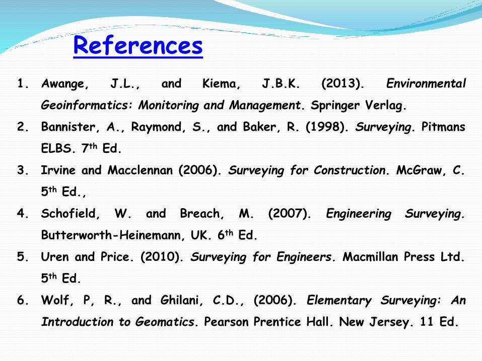
References
1. Awange, J.L., and Kiema, J.B.K. (2013). Environmental
Geoinformatics: Monitoring and Management. Springer Verlag.
2. Bannister, A., Raymond, S., and Baker, R. (1998). Surveying. Pitmans
ELBS. 7th Ed.
3. Irvine and Macclennan (2006). Surveying for Construction. McGraw, C.
5th Ed.,
4. Schofield, W. and Breach, M. (2007). Engineering Surveying.
Butterworth-Heinemann, UK. 6th Ed.
5. Uren and Price. (2010). Surveying for Engineers. Macmillan Press Ltd.
5th Ed.
6. Wolf, P, R., and Ghilani, C.D., (2006). Elementary Surveying: An
Introduction to Geomatics. Pearson Prentice Hall. New Jersey. 11 Ed.

Course Assignment/Term Paper
Using suitable examples discuss the role of
Geoinformatics in the monitoring and management of
environmental pollution.

Lecture Outline
Part 2: Traversing
Overview of Control Surveys
Concept of Traversing
Traverse Computation
Accuracy of Traversing
Part 1: Background
Basic Principle of Surveying
Datum Concept
Tenets of Survey Practice
Part 3: Vertical Control
Introduction and Definitions
Principle of Levelling
Sources of Errors
Applications of Levelling
Part 4: Earthworks
Computation of Areas and Volumes
Mass Haul Diagrams
Part 1: Background
Basic Principle of Surveying
Datum Concept
Tenets of Survey Practice

Basic Principle of Surveying
1) Working from the “whole to the part”. First
provide control using methods with higher
accuracy followed by detail mapping using
lower accuracy and cheaper methods.
2) Always perform independent checks. Make
more observations than the basic minimum
needed.
3) Specifications and accuracy required.
Datum ConceptBasic problem in Surveying is to determine the position
(measure) of features on Earth’s curved surface and
map (coordinate) them for diverse purposes often onto
a plane.
Datum refers to a plane or surface to which positions
and elevations of points are referenced.
Ellipsoid is reference surface in geodetic surveys.
Best fitting ellipsoid is selected.
For heighting the most commonly adopted datum is
the Mean Sea Level. This is taken with data from
coastal tide gauges over several years.
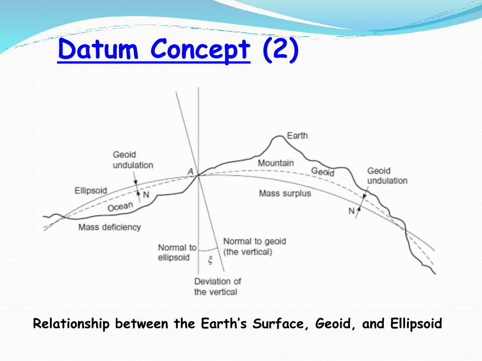
Datum Concept (2)
Relationship between the Earth’s Surface, Geoid, and Ellipsoid
Tenets of Survey Practice
Complete in shortest possible time.
Complete at the least possible cost.
Complete according to client instruction(s) and
survey manual specifications.
Complete using instrumentation of appropriate
accuracy.
Part 2: Traversing
Horizontal Control Surveys
Concept of Traversing
Traverse Computation
Accuracy of Traversing
In line with the Principle of Surveying a control
survey provides a framework of survey points,
whose relative positions are known to
prescribed degrees of accuracy.
The areas covered by these points may extend
over a whole country and form the basis for the
national maps of that country.
Alternatively the area may be relatively small,
encompassing a construction site for which a
large-scale plan is required. Although the areas
covered in construction are usually quite small,
the accuracy may be required to a very high
order.
Horizontal Control Surveys
Horizontal Control Surveys (2)
Hence control networks provide a reference
framework of points for:
(1) Topographic mapping and large-scale plan
production.
(2) Dimensional control of construction work.
(3) Deformation surveys for all manner of structures,
both new and old.
(4) The extension and densification of existing control
networks.
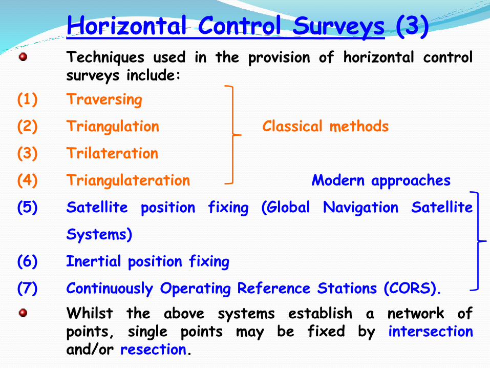
Horizontal Control Surveys (3)Techniques used in the provision of horizontal controlsurveys include:
(1) Traversing
(2) Triangulation Classical methods
(3) Trilateration
(4) Triangulateration Modern approaches
(5) Satellite position fixing (Global Navigation Satellite
Systems)
(6) Inertial position fixing
(7) Continuously Operating Reference Stations (CORS).
Whilst the above systems establish a network ofpoints, single points may be fixed by intersectionand/or resection.
Since the advent of EDM equipment, traversinghas emerged as the most popular method ofestablishing control networks not only inengineering surveying but also in geodetic work.Traverse networks are, to a large extent, freeof the limitations imposed on the other systemsand have the following advantages:
(1) Much less reconnaissance and organizationrequired in establishing a single line of easilyaccessible stations compared with the laying outof well-conditioned geometric figures.
(2) The limitations imposed on the other systems bytopographic conditions do not apply totraversing.
Concept of Traversing
Concept of Traversing (2)
(3) The extent of observations to only two stationsat a time is relatively small and flexiblecompared with the extensive angular and/orlinear observations at stations in the othersystems. It is thus much easier to organize.
(4) Traverse networks are free of the strength offigure considerations so characteristic oftriangular systems. Thus once again theorganizational requirements are reduced.
(5) Scale error does not accrue as in triangulation,whilst the use of longer sides, easily measuredwith EDM equipment, reduces azimuth swingerrors.

(6) Traverse stations can usually be chosen so as to
be easily accessible, as well as convenient for
the subsequent densification of lower order
control.
(7) Traversing permits the control to closely follow
the route of a highway, pipeline or tunnel, etc.,
with the minimum number of stations.
From the logistical point of view, traversing is
far superior to the other classical horizontal
control methods and offers at least equivalent
accuracy.
Concept of Traversing (3)
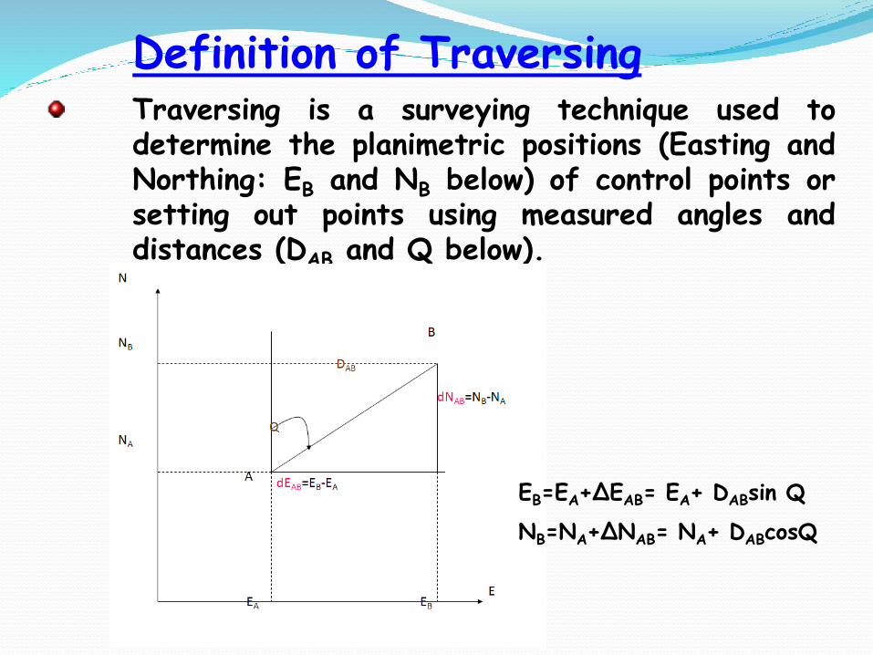
Definition of TraversingTraversing is a surveying technique used todetermine the planimetric positions (Easting andNorthing: EB and NB below) of control points orsetting out points using measured angles anddistances (DAB and Q below).
EB=EA+ΔEAB= EA+ DABsin Q
NB=NA+ΔNAB= NA+ DABcosQ
In traversing, the relative position of control
points is fixed by measuring the horizontal angle
at each point, subtended by the adjacent
stations, and the horizontal distance between
consecutive pairs of stations.
The liability of a traverse to undetected error
makes it essential that there should be some
external check on its accuracy. Hence, the
traverse needs to commence from and connect
into known points of greater accuracy than the
traverse.
Types of Traverses
Types of Traverses (2)
In this way, the error vector of misclosure canbe quantified and distributed throughout thenetwork, to produce geometric correctness. Sucha traverse is called a ‘link’ traverse.The link traverse has certain advantages overthe remaining types, in that systematic error indistance measurement and orientation are clearlyrevealed by the error vector.Alternatively, the error vector can be obtainedby completing the traverse back to its startingorigin. Such a traverse is called a ‘polygonal’ or‘loop’ traverse.
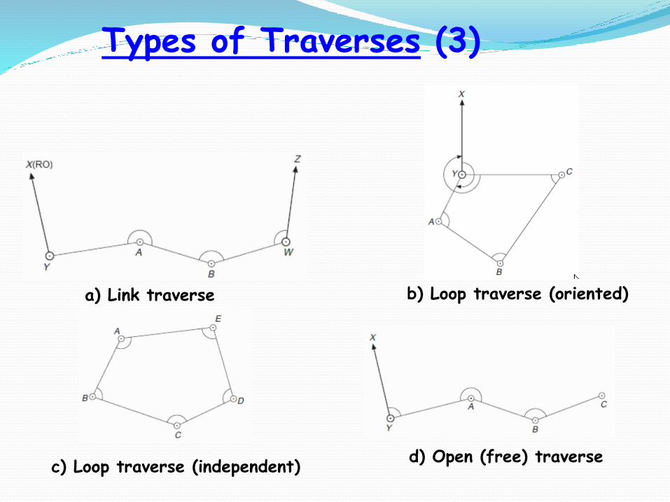
Types of Traverses (3)
a) Link traverse b) Loop traverse (oriented)
d) Open (free) traversec) Loop traverse (independent)
Both the ‘link’ and ‘polygonal’ traverses are
generally referred to as ‘closed’ traverses.
The third type of traverse is the ‘free’ or
‘open’ traverse, which does not close back onto
any known point and which therefore has no way
of detecting or quantifying the errors.
Open traverses are not recommended due to
the lack of checks. Nevertheless, it is
frequently utilized in mining and tunnelling work
because of the physical restriction on closure.
Types of Traverses (4)
Field Procedure
Reconnaissance is a vitally important part of any
survey project. Its purpose here is to decide
the best location for the traverse points.
In the first instance the points should be
intervisible from the point of view of traverse
observations.
If the purpose of the control network is the
location of topographic detail only, then they
should be positioned to afford the best view of
the terrain, thereby ensuring that the maximum
amount of detail can be surveyed from each
point.
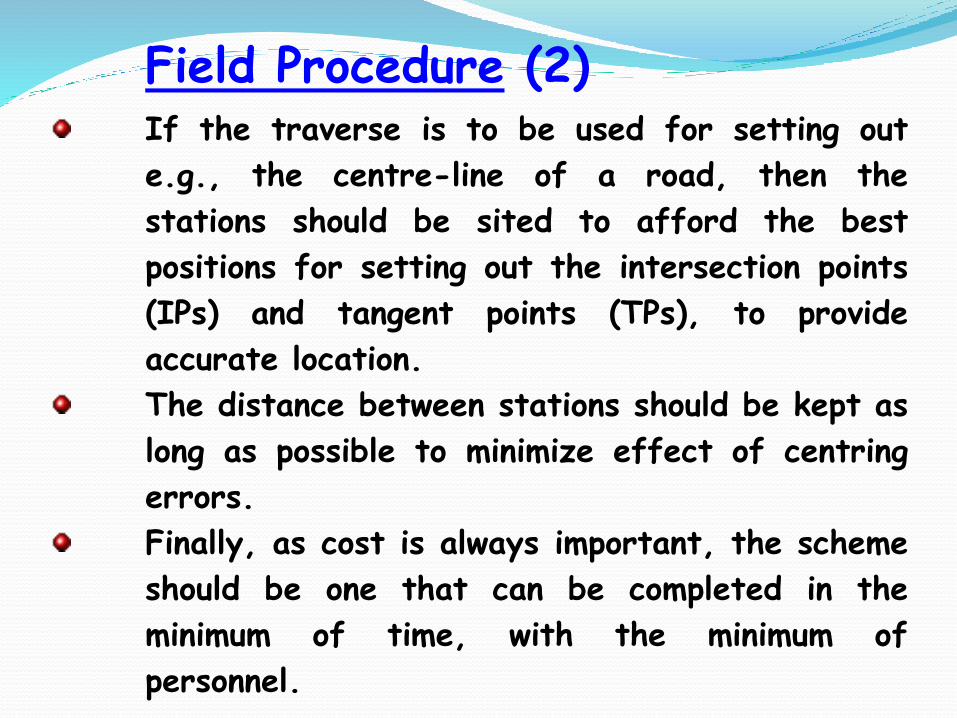
Field Procedure (2)If the traverse is to be used for setting out
e.g., the centre-line of a road, then the
stations should be sited to afford the best
positions for setting out the intersection points
(IPs) and tangent points (TPs), to provide
accurate location.
The distance between stations should be kept as
long as possible to minimize effect of centring
errors.
Finally, as cost is always important, the scheme
should be one that can be completed in the
minimum of time, with the minimum of
personnel.
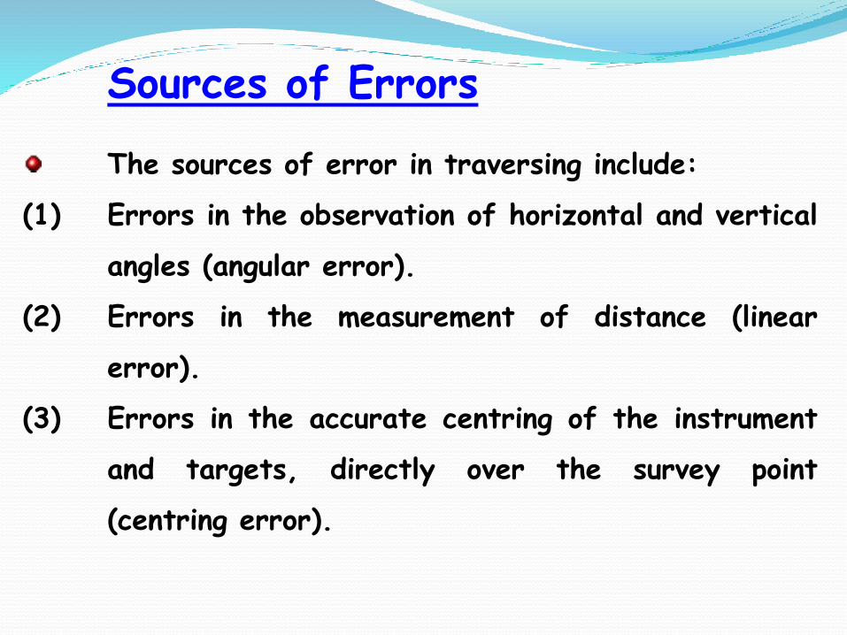
Sources of Errors
The sources of error in traversing include:
(1) Errors in the observation of horizontal and vertical
angles (angular error).
(2) Errors in the measurement of distance (linear
error).
(3) Errors in the accurate centring of the instrument
and targets, directly over the survey point
(centring error).
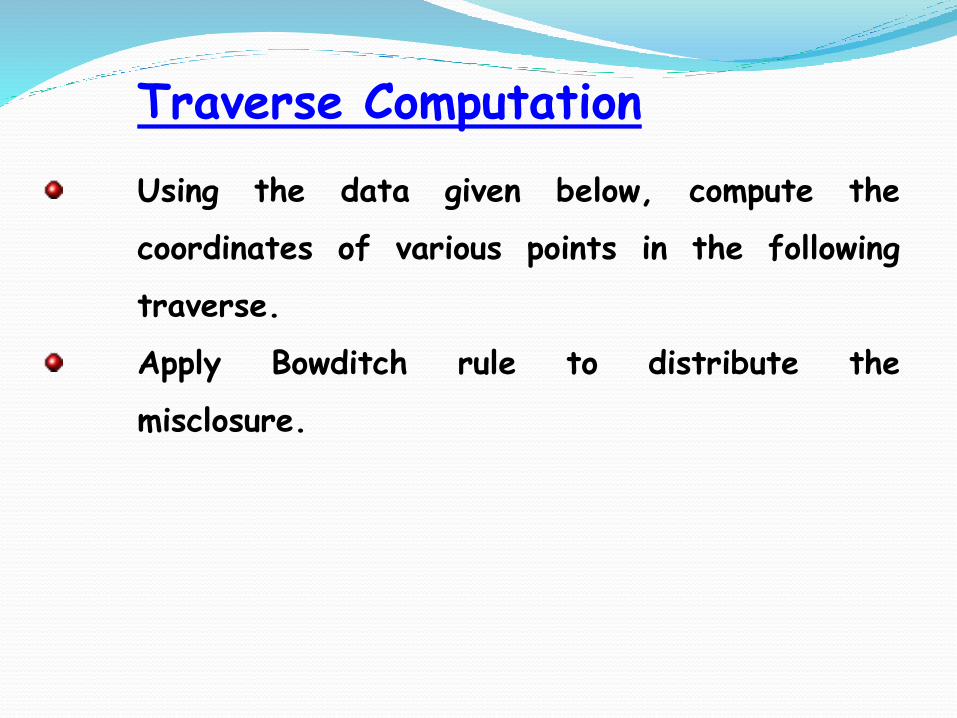
Traverse Computation
Using the data given below, compute the
coordinates of various points in the following
traverse.
Apply Bowditch rule to distribute the
misclosure.
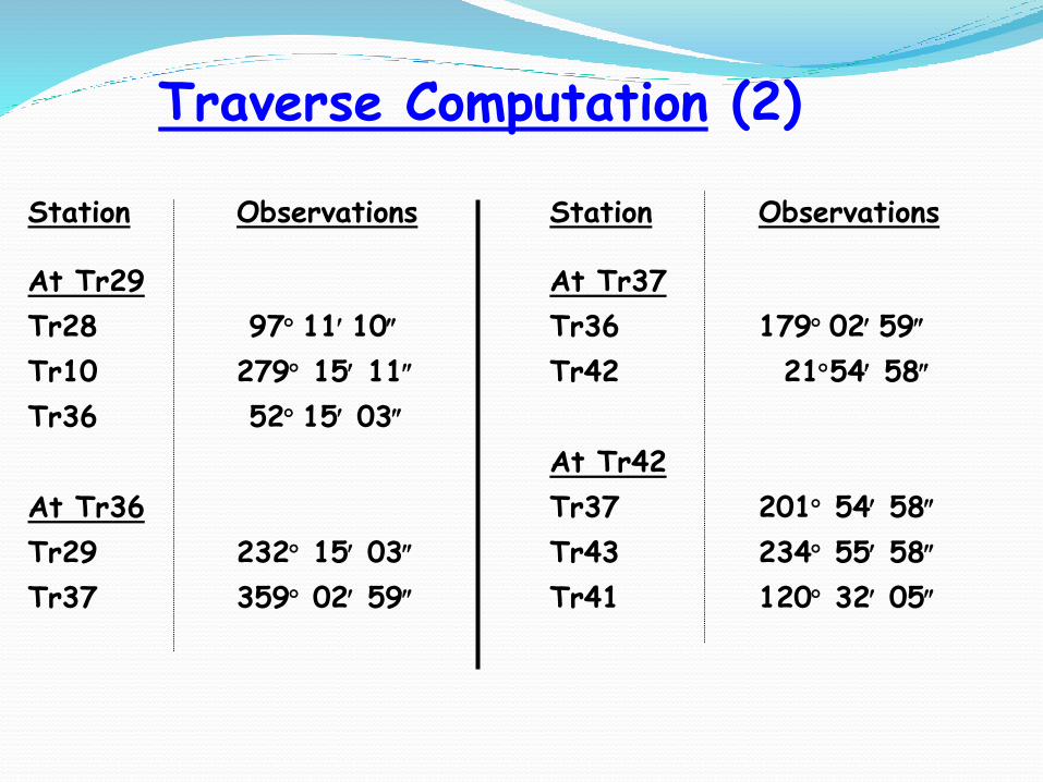
Station Observations Station Observations
At Tr29 At Tr37
Tr28 97 11 10 Tr36 179 02 59
Tr10 279 15 11 Tr42 2154 58
Tr36 52 15 03
At Tr42
At Tr36 Tr37 201 54 58
Tr29 232 15 03 Tr43 234 55 58
Tr37 359 02 59 Tr41 120 32 05
Traverse Computation (2)
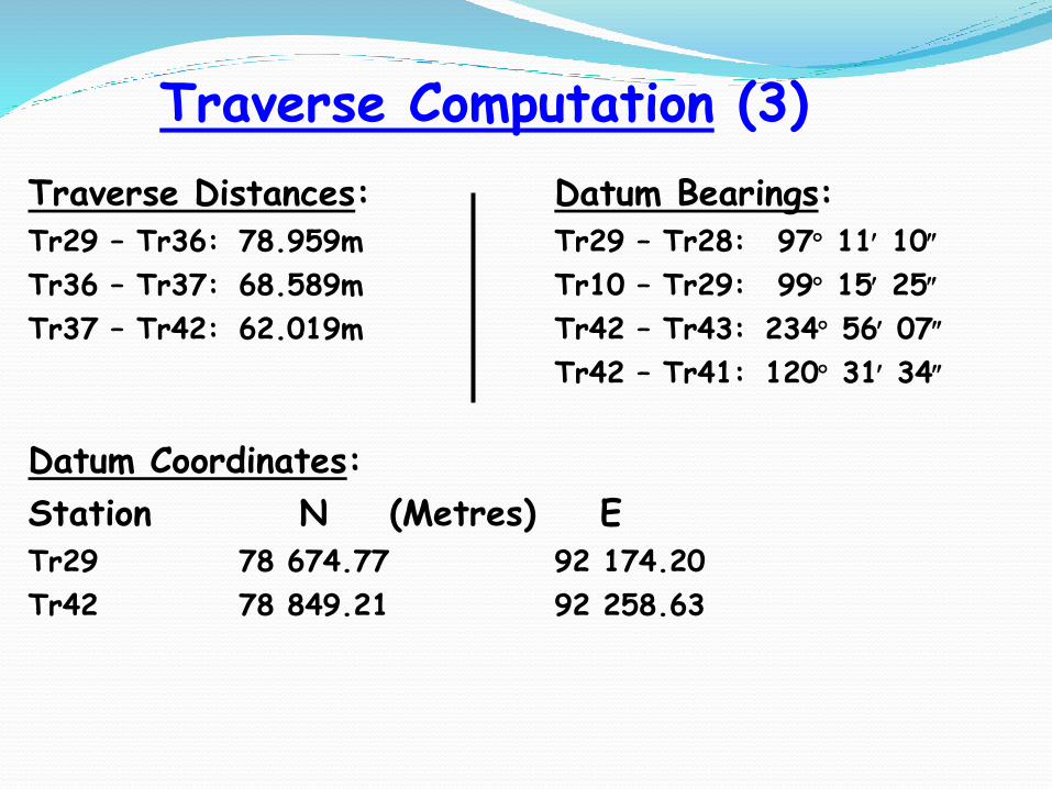
Traverse Computation (3)
Traverse Distances: Datum Bearings:Tr29 – Tr36: 78.959m Tr29 – Tr28: 97 11 10
Tr36 – Tr37: 68.589m Tr10 – Tr29: 99 15 25
Tr37 – Tr42: 62.019m Tr42 – Tr43: 234 56 07
Tr42 – Tr41: 120 31 34
Datum Coordinates:
Station N (Metres) ETr29 78 674.77 92 174.20
Tr42 78 849.21 92 258.63
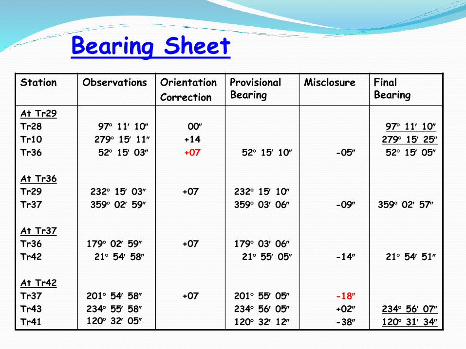
Bearing Sheet
Station Observations Orientation
Correction
Provisional Bearing
Misclosure Final Bearing
At Tr29
Tr28
Tr10
Tr36
At Tr36
Tr29
Tr37
At Tr37
Tr36
Tr42
At Tr42
Tr37
Tr43
Tr41
97 11 10
279 15 11
52 15 03
232 15 03
359 02 59
179 02 59
21 54 58
201 54 58
234 55 58120 32 05
00
+14
+07
+07
+07
+07
52 15 10
232 15 10
359 03 06
179 03 06
21 55 05
201 55 05
234 56 05
120 32 12
-05
-09
-14
-18
+02
-38
97 11 10
279 15 25
52 15 05
359 02 57
21 54 51
234 56 07
120 31 34
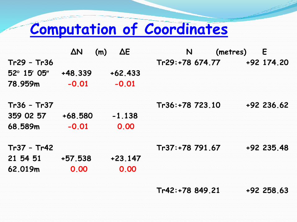
Computation of Coordinates
ΔN (m) ΔE N (metres) E
Tr29 – Tr36 Tr29:+78 674.77 +92 174.20
52 15 05 +48.339 +62.433
78.959m -0.01 -0.01
Tr36 – Tr37 Tr36:+78 723.10 +92 236.62
359 02 57 +68.580 -1.138
68.589m -0.01 0.00
Tr37 – Tr42 Tr37:+78 791.67 +92 235.48
21 54 51 +57.538 +23.147
62.019m 0.00 0.00
Tr42:+78 849.21 +92 258.63

ΔN (m) ΔE
By Datum: 174.440 84.430
By Traverse: 174.456 84.442
Misclosure: -0.016 -0.012
Length of Traverse = 209.567m
Accuracy = Sqrt{(-0.016)2+(-0.012)2}/209.567 = 1 in 13,000
(approx)
Computation of Coordinates (2)

Accuracy of Traversing
Traversing is generally more accurate thanclassical triangulation and trilateration.Due to the weak geometry of a traverse, itgenerally has only three degrees of freedom (thatis three redundant observations), it is difficult toarrive at an estimate of accuracy.Although there have been many attempts toproduce equations defining the accuracy of atraverse, at the present time the best approach isa strength analysis using variance–covariancematrices from a least squares adjustment.
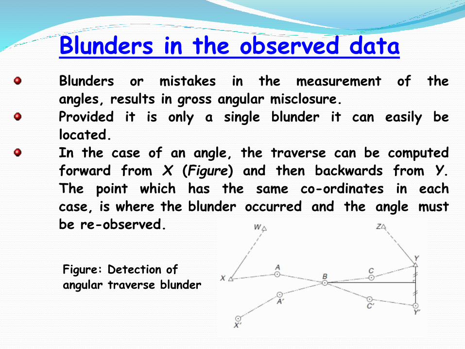
Blunders in the observed data
Blunders or mistakes in the measurement of theangles, results in gross angular misclosure.Provided it is only a single blunder it can easily belocated.In the case of an angle, the traverse can be computedforward from X (Figure) and then backwards from Y.The point which has the same co-ordinates in eachcase, is where the blunder occurred and the angle mustbe re-observed.
Figure: Detection of angular traverse blunder
Blunders in the observed data (2)
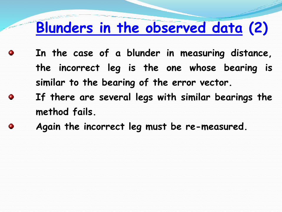
In the case of a blunder in measuring distance,
the incorrect leg is the one whose bearing is
similar to the bearing of the error vector.
If there are several legs with similar bearings the
method fails.
Again the incorrect leg must be re-measured.
Part 3: Vertical Control
Introduction and Definitions
Principle of Levelling
Sources of Errors
Applications of Levelling
The process of determining elevations (heights)of points of interest above or below a referencedatum or differences in elevations.For most practical applications only thedifference in elevation between points ofinterest and not absolute heights is oftenrequired.Used in all aspects of surveying, particularly forengineering surveys, route surveys, construction,etc.Different methods may be used for estimatingheights or height differences including;differential levelling, barometric heighting,trigonometric heighting, gravimetry andsatellite positioning etc.
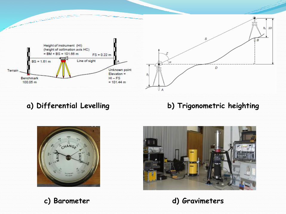
Overview of Levelling
a) Differential levelling: basic idea involves obtaining of heightdifference between points by measuring their vertical distancefrom a horizontal line of sight.
b) Trigonometric heighting: method is generally used indetermination of elevation differences of lower accuracy thanspirit levelling. It is useful where it is very difficult (orimpossible) for differential levelling to be undertaken (e.g.towers, spires, mountain ranges etc).
c) Barometric heighting: method consists of reading air pressuredifferences from which elevation differences are computed.
d) Gravimetry: by measuring the gravitational potential variationbetween different points it is possible to correlate this todifferences in heights.
d) Satellite Positioning: method is poised for extensive use in thefuture with its only drawback being the determination of theseparation between the geoid and ellipsoid in areas of interest.
Comparison of Various Heighting Methods
a) Differential Levelling b) Trigonometric heighting
c) Barometer d) Gravimeters
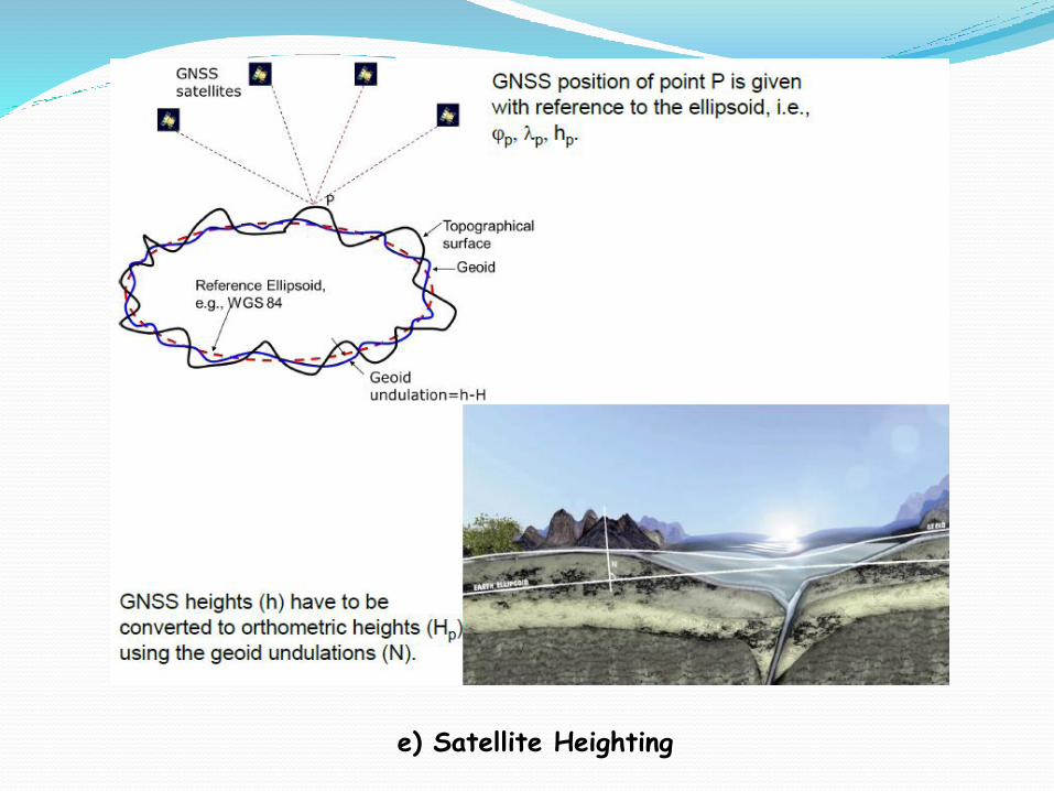
e) Satellite Heighting
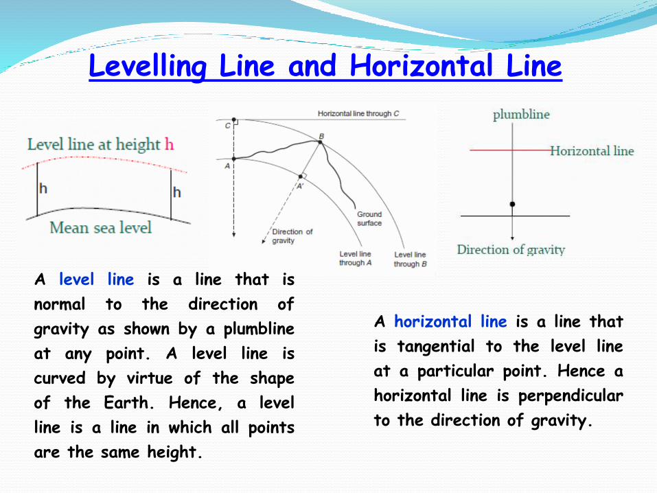
A horizontal line is a line that
is tangential to the level line
at a particular point. Hence a
horizontal line is perpendicular
to the direction of gravity.
Levelling Line and Horizontal Line
A level line is a line that is
normal to the direction of
gravity as shown by a plumbline
at any point. A level line is
curved by virtue of the shape
of the Earth. Hence, a level
line is a line in which all points
are the same height.

Basic Concept
Datum: A level surface to which elevations of points may
be referenced. The most commonly adopted datum is the
Mean Sea Level (MSL).Reduced level: The elevation (above or below) of a pointin relation to the Datum.Benchmark (BM): A permanent monument or feature for
which elevation is known. BMs are built on stable rock.
Three (3) types of benchmarks can be distinguished:1) Fundamental benchmarks (FBMs): Very stable concrete structures
most often built into rock forming part of the primary levelling
network.
2) Ordinary benchmarks: Concrete points or marks on rocks, culverts,
bridges etc constructed between FBMs.
3) Temporary benchmarks (TBMs): Stable points established in the course
of a survey between established benchmarks, which may be some
distance away.
Datums, Reduced Levels and Benchmarks
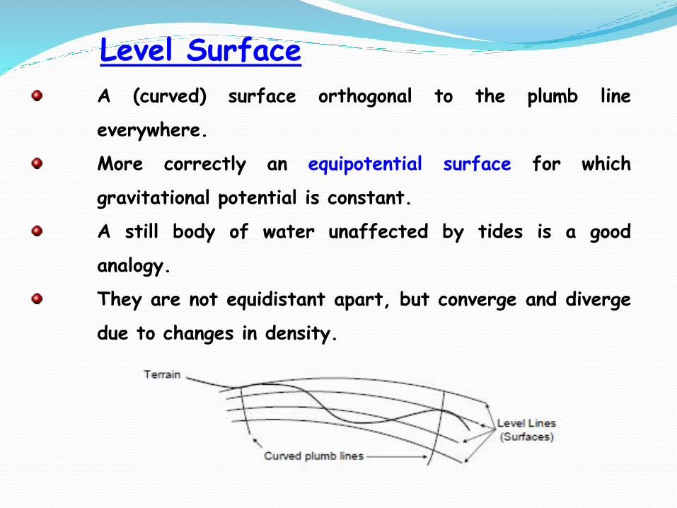
A (curved) surface orthogonal to the plumb line
everywhere.
More correctly an equipotential surface for which
gravitational potential is constant.
A still body of water unaffected by tides is a good
analogy.
They are not equidistant apart, but converge and diverge
due to changes in density.
Level Surface
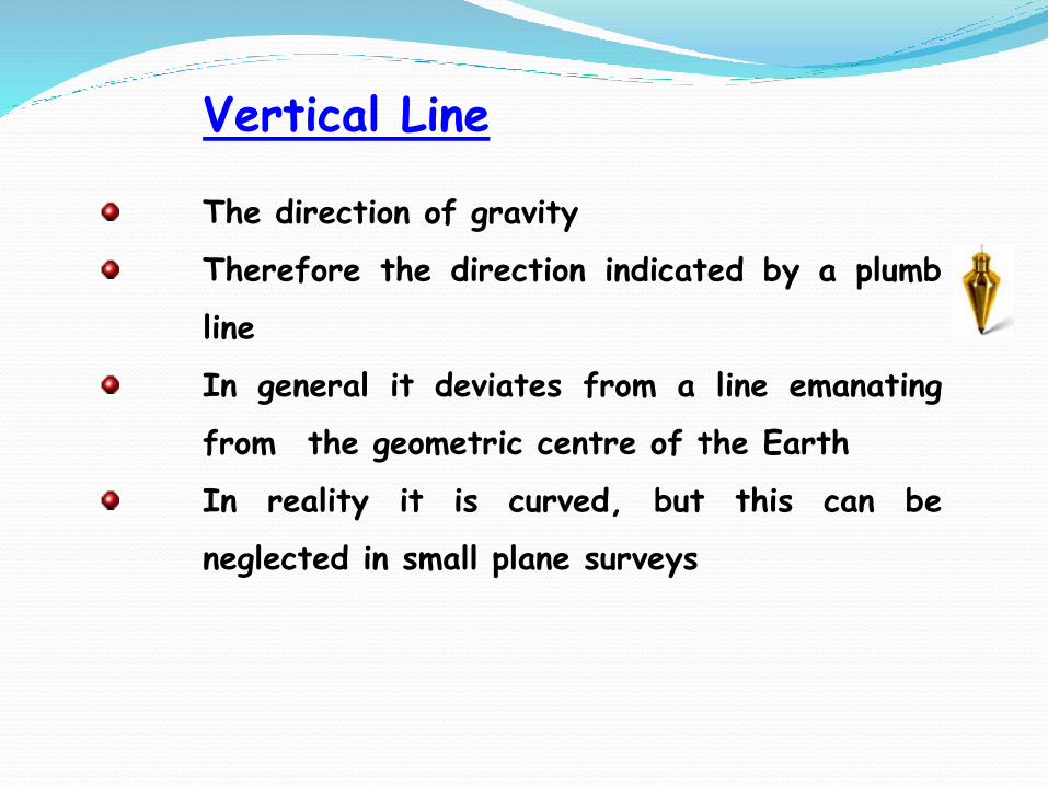
Vertical Line
The direction of gravity
Therefore the direction indicated by a plumb
line
In general it deviates from a line emanating
from the geometric centre of the Earth
In reality it is curved, but this can be
neglected in small plane surveys
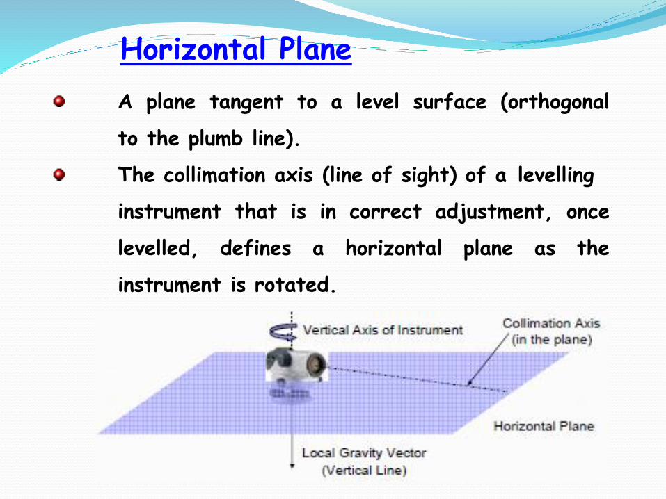
Horizontal Plane
A plane tangent to a level surface (orthogonal
to the plumb line).
The collimation axis (line of sight) of a levelling
instrument that is in correct adjustment, once
levelled, defines a horizontal plane as the
instrument is rotated.
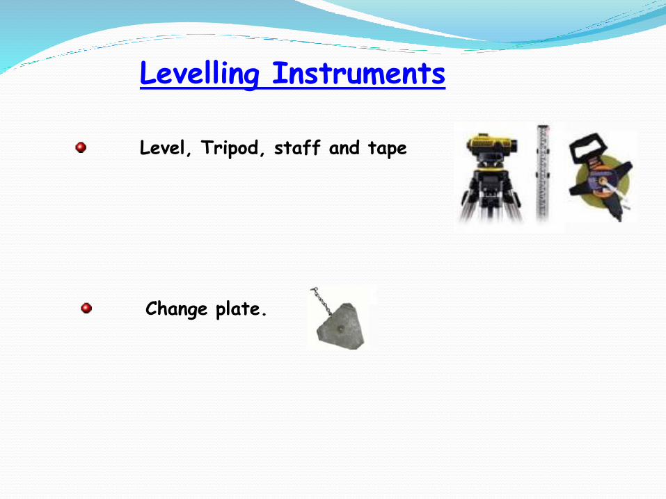
Levelling Instruments
Level, Tripod, staff and tape
Change plate.
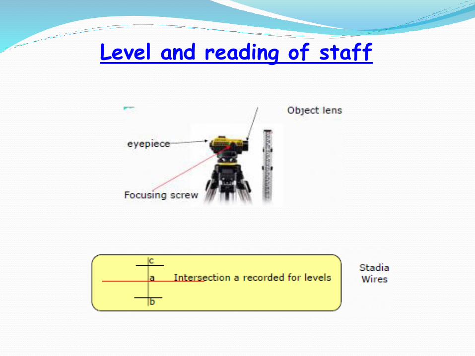
Level and reading of staff
Level and reading of staff
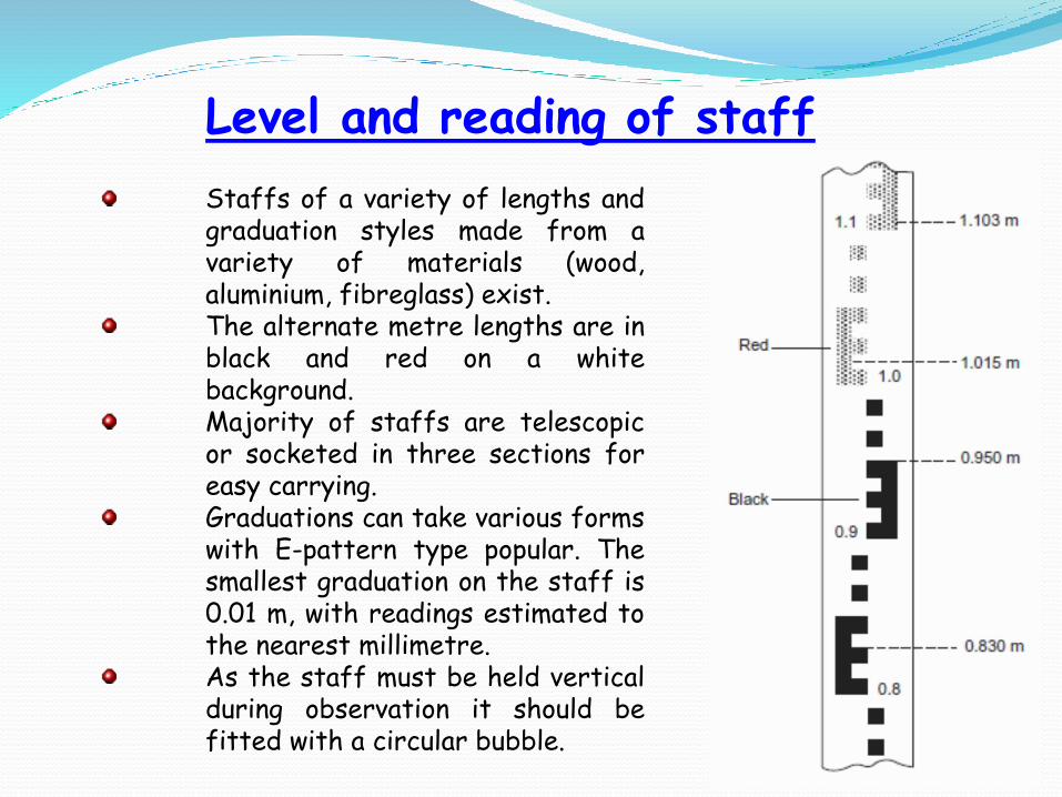
Staffs of a variety of lengths andgraduation styles made from avariety of materials (wood,aluminium, fibreglass) exist.The alternate metre lengths are inblack and red on a whitebackground.Majority of staffs are telescopicor socketed in three sections foreasy carrying.Graduations can take various formswith E-pattern type popular. Thesmallest graduation on the staff is0.01 m, with readings estimated tothe nearest millimetre.As the staff must be held verticalduring observation it should befitted with a circular bubble.
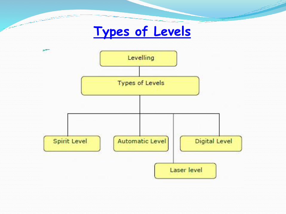
Types of Levels
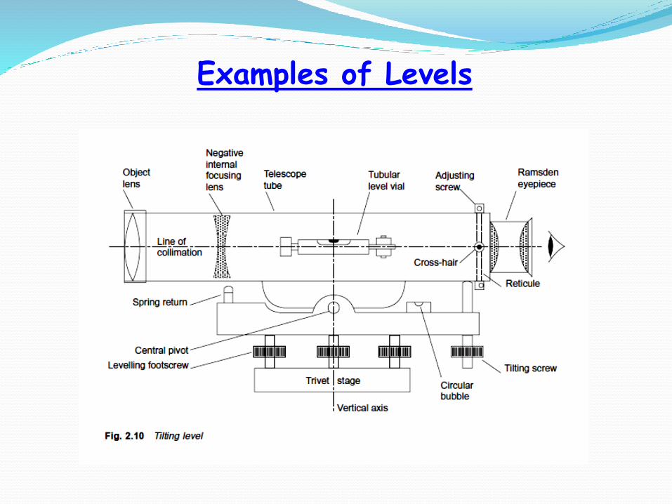
Examples of Levels
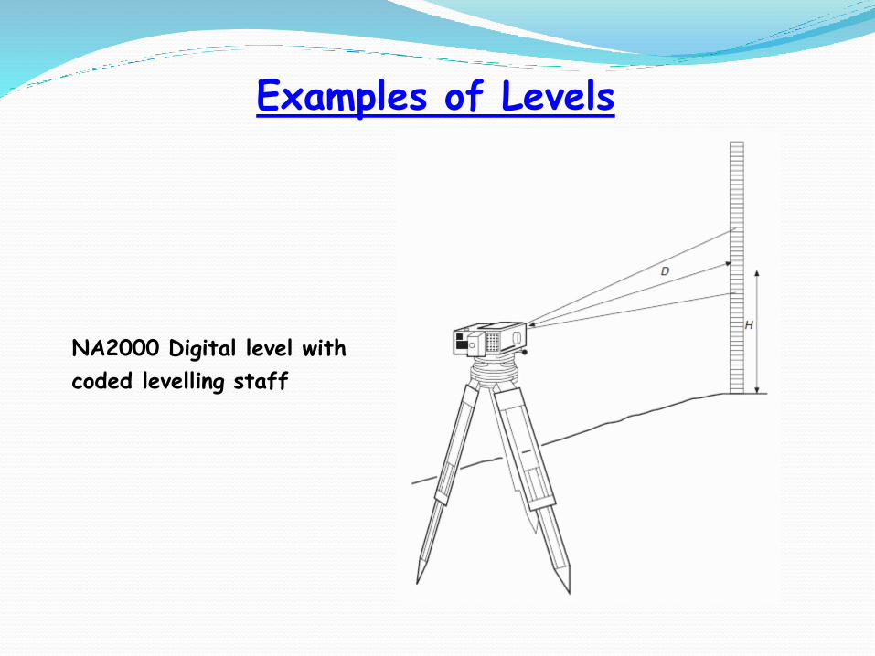
Examples of Levels
NA2000 Digital level with
coded levelling staff
Two Peg Test
This test is often conducted before using a level for any
levelling exercise.
The purpose of the test is find out to if the line of
collimation is parallel to the bubbles tube axis.
Collimation error occurs if the line of sight is not truly
horizontal when the bubble is centred. The line of sight
may be inclined either upwards or downwards from
the horizontal.

Levelling Procedure
A horizontal line of sight is established using some
form of levelling mechanism:
Spirit level tube
Swinging pendulum
A graduated staff is read through the telescope of
the level.
The elevation of points can be established by first
reading the staff on a bench mark.
The staff is then moved to the desired point, the
level is turned and the staff is read again.
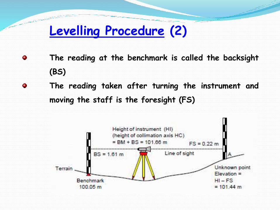
Levelling Procedure (2)
The reading at the benchmark is called the backsight
(BS)
The reading taken after turning the instrument and
moving the staff is the foresight (FS)
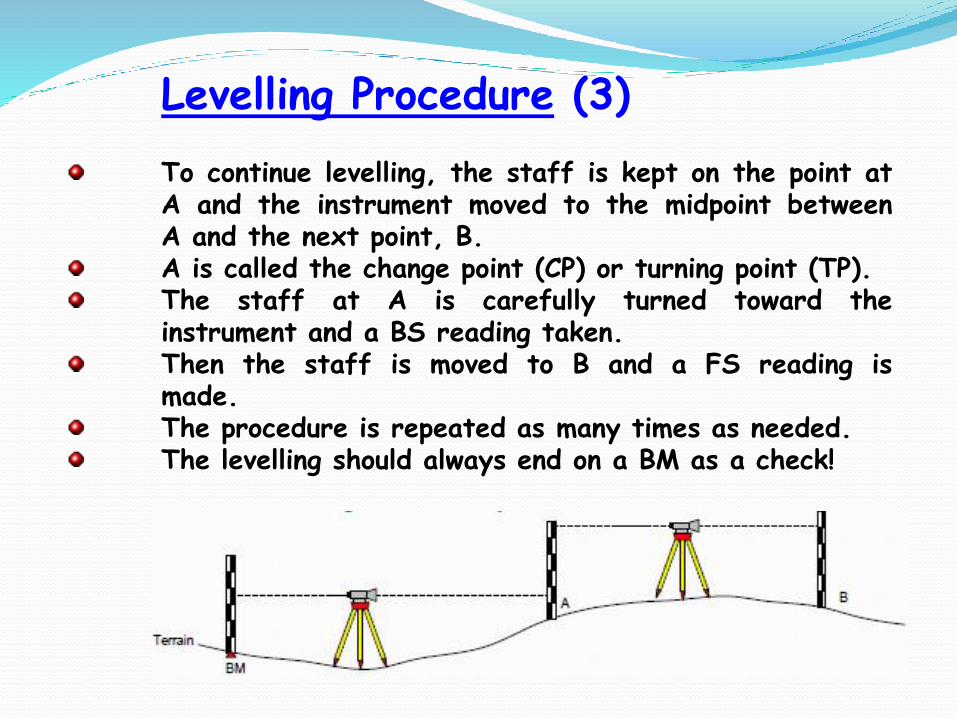
Levelling Procedure (3)
To continue levelling, the staff is kept on the point atA and the instrument moved to the midpoint betweenA and the next point, B.A is called the change point (CP) or turning point (TP).The staff at A is carefully turned toward theinstrument and a BS reading taken.Then the staff is moved to B and a FS reading ismade.The procedure is repeated as many times as needed.The levelling should always end on a BM as a check!

Levelling Procedure (4)
Two note reduction methods for calculating elevations
from the BS and FS observations exist.
Each use only two equations for the computations.
Height of Collimation method HC = Elev + BS
Elev = HC – FS
Rise and Fall method Rise (or Fall) = BS – FS
Elev = Previous Elev + Rise (or Fall)
A Fall is simply a negative Rise
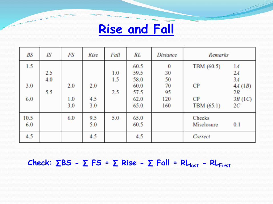
Rise and Fall
Check: ∑BS - ∑ FS = ∑ Rise - ∑ Fall = RLlast - RLFirst

Height of Collimation
Check: ∑BS - ∑ FS = RLlast - RLFirst
Applied when points of interest can be seen
Accuracy in Levelling
Many factors affect accuracy of ordinary levelling:
Reading of staff.
Bubble not being central.
Instrument (level) being out of adjustment. Ensuring
that backsights and foresights are equal in length
lessens effects of maladjustment.
Differential settlement of the tripod.
Tilting and settlement of the staff.
Sensitivity of the bubble or compensator.
Acceptable Misclosures
Maximum acceptable misclosure depends on class of
levelling and specifications for the particular survey.
As a guideline the following figures give an indication of
misclosures for various classes:
Precise levelling: 4K
2nd order levelling: 8K
3rd order levelling: 12K.
Ordinary levelling falls into this category. On rough
ground, allowance may be made for misclosures of up to
30K (Where K is the total distance levelled in
kilometres).
Precise Levelling
This class of levelling requires further refinement tofield technique and instrumentation to that applied inordinary levelling.The accuracy requirements for this class of levellingare more stringent than for ordinary levelling.Typical rules governing field technique for preciselevelling include:
1) Backsights and foresights are made equal in length,two staffs being used.
2) Readings are made to one particular staff at eachsetup, and there being an even number of set ups.Readings are made to all three hairs of the reticuleat each set up and a special format for booking ofreadings used.
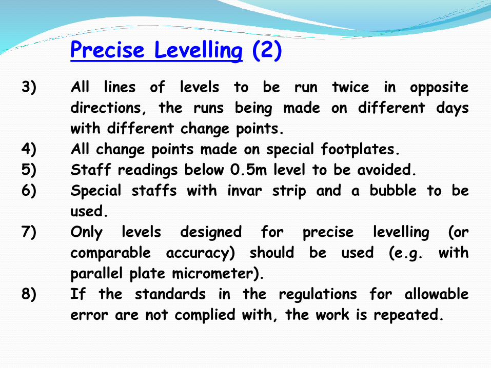
Precise Levelling (2)
3) All lines of levels to be run twice in opposite
directions, the runs being made on different days
with different change points.
4) All change points made on special footplates.
5) Staff readings below 0.5m level to be avoided.
6) Special staffs with invar strip and a bubble to be
used.
7) Only levels designed for precise levelling (or
comparable accuracy) should be used (e.g. with
parallel plate micrometer).
8) If the standards in the regulations for allowable
error are not complied with, the work is repeated.
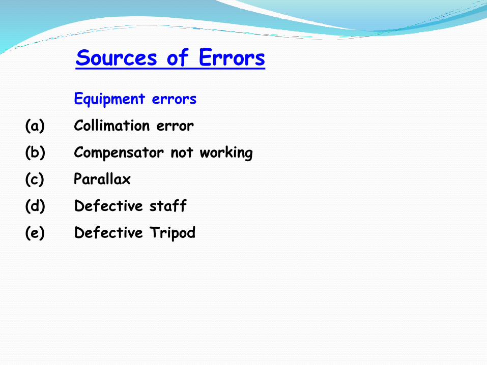
Sources of Errors
Equipment errors
(a) Collimation error
(b) Compensator not working
(c) Parallax
(d) Defective staff
(e) Defective Tripod
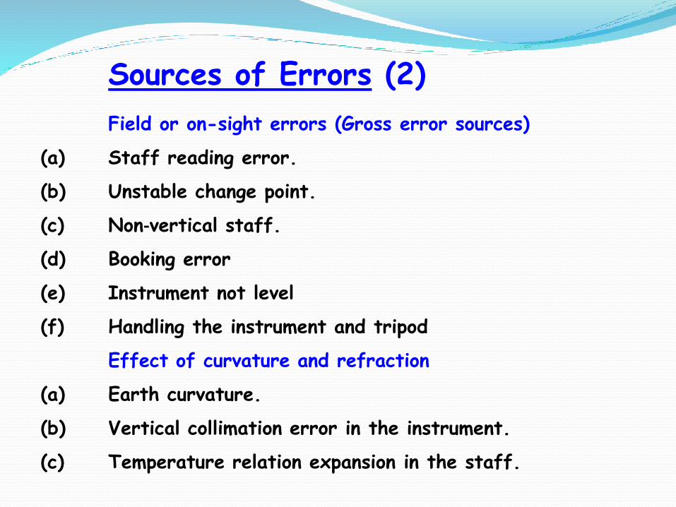
Sources of Errors (2)
Field or on-sight errors (Gross error sources)
(a) Staff reading error.
(b) Unstable change point.
(c) Non‐vertical staff.
(d) Booking error
(e) Instrument not level
(f) Handling the instrument and tripod
Effect of curvature and refraction
(a) Earth curvature.
(b) Vertical collimation error in the instrument.
(c) Temperature relation expansion in the staff.
How to Reduce Errors
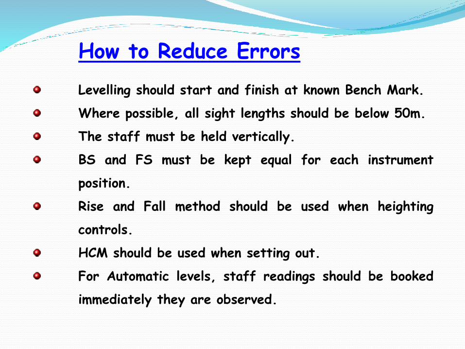
Levelling should start and finish at known Bench Mark.
Where possible, all sight lengths should be below 50m.
The staff must be held vertically.
BS and FS must be kept equal for each instrument
position.
Rise and Fall method should be used when heighting
controls.
HCM should be used when setting out.
For Automatic levels, staff readings should be booked
immediately they are observed.
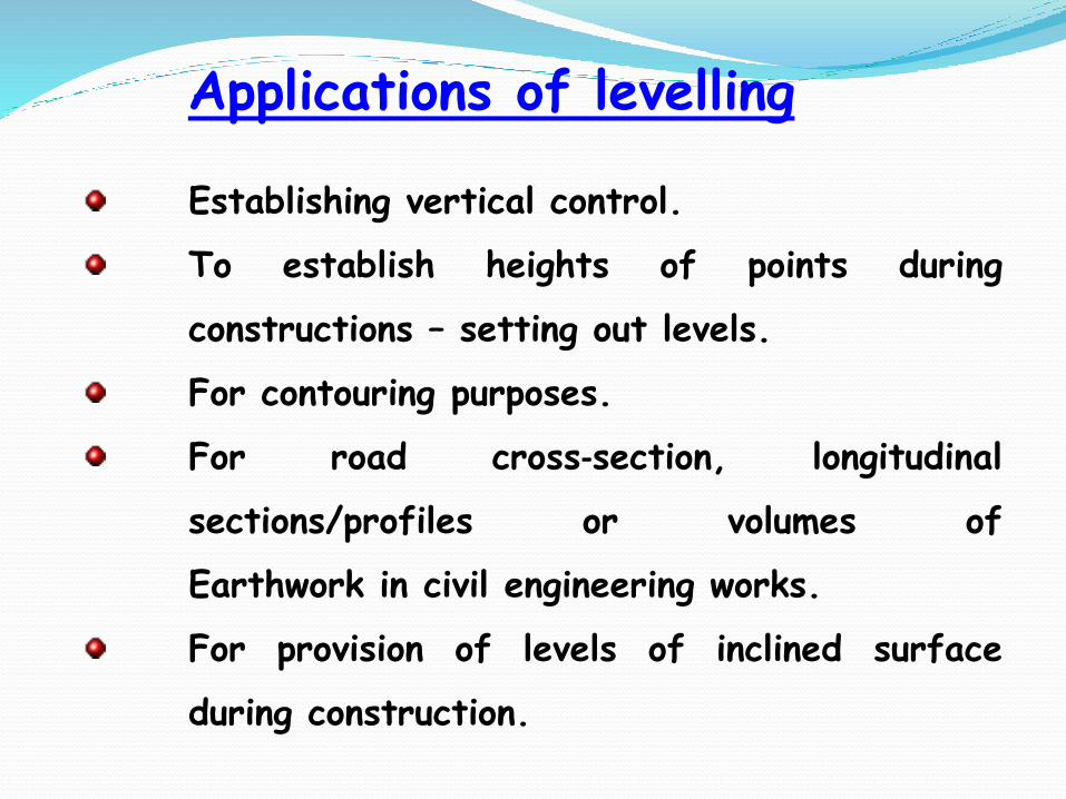
Establishing vertical control.
To establish heights of points during
constructions – setting out levels.
For contouring purposes.
For road cross‐section, longitudinal
sections/profiles or volumes of
Earthwork in civil engineering works.
For provision of levels of inclined surface
during construction.
Applications of levelling

Part 4: Earthworks
Overview
Computation of Areas and Volumes
Mass Haul Diagrams

Estimation of areas and volumes is basic to
most engineering schemes such as route
alignment, reservoirs, tunnels, etc.
Excavation and hauling of material is the
most significant and costly aspect of the
work, on which profit or loss may depend.
Areas may be required in connection with
the purchase or sale of land, with the
subdivision of land or with the grading of
land.
Overview

Earthwork volumes are estimated to:
i) enable route alignment to be located at such
lines and levels that cut and fill are balanced
as far as practicable;
ii) to enable contract estimates of time and
cost to be made for proposed work;
iii) to form the basis of payment for work
carried out.
Overview (2)
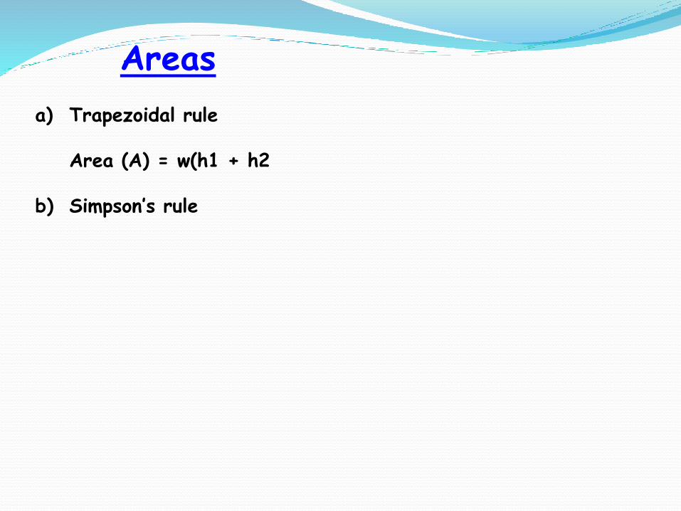
Areas
a) Trapezoidal rule
Area (A) = w(h1 + h2
b) Simpson’s rule
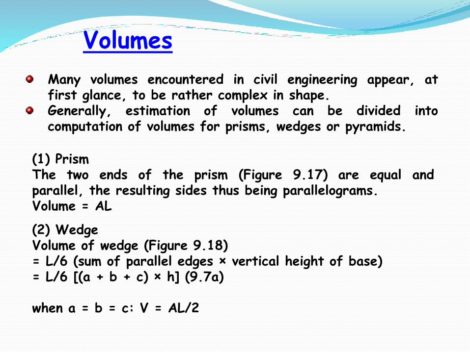
Many volumes encountered in civil engineering appear, atfirst glance, to be rather complex in shape.Generally, estimation of volumes can be divided intocomputation of volumes for prisms, wedges or pyramids.
(1) PrismThe two ends of the prism (Figure 9.17) are equal andparallel, the resulting sides thus being parallelograms.Volume = AL
Volumes
(2) WedgeVolume of wedge (Figure 9.18) = L/6 (sum of parallel edges × vertical height of base)= L/6 [(a + b + c) × h] (9.7a)
when a = b = c: V = AL/2

Mass-haul diagrams (MHD) are used to comparethe economy of various methods of earthworkdistribution on road or railway constructionschemes.By the combined use of the MHD plotted directlybelow the longitudinal section of the survey centre-line, one can find:
(1) The distances over which cut and fill will balance.(2) Quantities of materials to be moved and the
direction of movement.(3) Areas where earth may have to be borrowed or
wasted and the amounts involved.(4) The best policy to adopt to obtain the most
economic use of plant.
Mass-Haul Diagrams