autonomous soft robotic fish capable of escape maneuvers ... · autonomous soft robotic fish...
TRANSCRIPT
ORIGINAL ARTICLE
Autonomous Soft Robotic Fish Capable of EscapeManeuvers Using Fluidic Elastomer Actuators
Andrew D. Marchese,1 Cagdas D. Onal,1,2 and Daniela Rus1
Abstract
In this work we describe an autonomous soft-bodied robot that is both self-contained and capable of rapid,continuum-body motion. We detail the design, modeling, fabrication, and control of the soft fish, focusing onenabling the robot to perform rapid escape responses. The robot employs a compliant body with embeddedactuators emulating the slender anatomical form of a fish. In addition, the robot has a novel fluidic actuationsystem that drives body motion and has all the subsystems of a traditional robot onboard: power, actuation,processing, and control. At the core of the fish’s soft body is an array of fluidic elastomer actuators. We designthe fish to emulate escape responses in addition to forward swimming because such maneuvers require rapidbody accelerations and continuum-body motion. These maneuvers showcase the performance capabilities ofthis self-contained robot. The kinematics and controllability of the robot during simulated escape responsemaneuvers are analyzed and compared with studies on biological fish. We show that during escape responses,the soft-bodied robot has similar input–output relationships to those observed in biological fish. The majorimplication of this work is that we show soft robots can be both self-contained and capable of rapidbody motion.
Introduction
Body compliance is a salient feature in many naturalsystems. Compliant bodies offer inherent robustness to
uncertainty, adaptability to environmental variation, and thecapacity to redirect and distribute applied forces. In an effortto make machines more capable, our aim is to exploit thisprinciple and design softness into robots.
In this work, we advance soft robotics by providinga method for creating and controlling autonomous, self-contained, soft-bodied systems. Specifically, we introduce anovel self-contained fluidic actuation system and control al-gorithms used to deliver continuum motion in soft robots. Wedemonstrate this soft actuation in a case study by building anautonomous soft-bodied robotic fish powered by an onboardenergy source (Fig. 1). The fish is novel in that it uses a softcontinuum body and an innovative fluidic actuation systemfor the soft body and has onboard autonomy. All power, ac-tuation, and computational systems are located onboard. Thecontinuum body has an embedded flexible spine and em-bedded anatomically proportioned musclelike actuators. Therobot is capable of forward swimming and performing agile
maneuvers, scaled versions of an escape response.* A fishwas chosen as a case study because it naturally exhibitscontinuum-body curvature, rapid motion during an escaperesponse,1,2 a compliant posterior that bends under hydro-dynamic resistance,3 and an anterior suitable for housing ri-gid supporting hardware.
We have evaluated the forward swimming and escape re-sponse maneuver of this soft robot in a suite of experiments.Extensive kinematic data have been collected on the escaperesponse, and we compare the performance of the robot withvarious studies on biological fish. We show that our roboticsystem, although on a different time scale, is able to emulatethe basic structure of an escape response and that the
1Department of Electrical Engineering and Computer Science, Massachusetts Institute of Technology, Cambridge, Massachusetts.2Department of Mechanical Engineering, Worcester Polytechnic Institute, Worcester, Massachusetts.
*Escape response maneuvers are characterized by rapid bodyaccelerations over very short durations and that often involve thebody initially bending into a ‘‘C’’ shape.1 Among vertebrates, theseare some of the most rapid maneuvers4 and subject of frequentstudy. The extremely agile behavior exhibited by fish during escaperesponse maneuvers is central to predator–prey interactions,5 andaccordingly escape response performance carries marked ecologicalsignificance.6–9 Recently, the hydrodynamics of the maneuver havebeen explored in great detail.2
SOFT ROBOTICSVolume 1, Number 1, 2014ª Mary Ann Liebert, Inc.DOI: 10.1089/soro.2013.0009
75

performed maneuvers have a similar input–output relation-ship as observed in biological fish.
Performance and autonomy are competing goals in fluid-powered soft robots. Some fluid-powered soft machines showpromising capabilities such as walking10 and leaping11 butare primarily driven by cumbersome external hardware lim-iting their practical use. Conversely, there are instances ofself-contained fluidic soft robots;12–14 however, because ofthe constraints imposed by bringing all supporting hardwareonboard, performance of these robots is severely limitedwhen compared with rigid-bodied robots. The primarytechnical challenge addressed by this work is the advance-ment of soft-bodied robots to simultaneously be capableof rapidly achieving continuum-body motion and be self-contained. We illustrate our proposed technical approach bydesigning and building a soft robot fish capable of emulatingthe escape response of fish because this maneuver ex-emplifies rapid and continuum-body motion and exhibits thehighest accelerations seen in fish.1
The soft robotic fish exhibits continuum motion thatconventional rigid-bodied robotic fish cannot achieve. Forinstance, although many notable robotic fish exist,15–19
these prior robotic systems have bodies composed of rigidsegments connected by fixed joints and are consequentlyincapable of reproducing the body kinematics observedduring agile escape response maneuvers. Previous at-tempts to recreate an escape response used a body com-posed of multiple position-controlled, rigid links;20–22
however, such fully actuated, rigid-bodied systems inher-ently fail to capture the continuum motion of the escaperesponse maneuver.
We build on several prior works that aim to create ro-botic fish using biologically inspired flexible posteriors. Self-propelling flexible foils driven by an external robotic actuatorhave been studied by Lauder and colleagues.23,24 Valdivia yAlvarado and Youcef-Toumi used a compliant body in thedesign of a robotic fish to mimic the swimming kinematics ofa natural fish.25 Similarly, the robot fish FILOSE26,27 has acompliant posterior and serves as a test bed for fishlikesensing and locomotion. Both of these systems are cable-driven and actuated with an onboard servomotor but lackautonomy and require an external power supply. Recently,researchers have developed a cable-driven, flexible spring-steel spine to model escape response behavior;28 however, inthis system the motor, control system, and power supply areexternal to the apparatus, and its motion is constrained. Longet al. have developed a flexible biomimetic vertebral columnused to propel an autonomous surface-swimming robot.29
The vehicle can also perform an escape response.30 Again, asingle servomotor is used to actuate the compliant spine.Although this system is autonomous, relative to the afore-mentioned work, only a small portion of the body is flexible,namely, its posterior tail, and because its large anterior is asurface vessel, the system is limited to surface swimming.Notably, the above-mentioned compliant-bodied robotic fishoperate on the principle of a passive, flexible mechanism
FIG. 1. Details of a soft-bodied robotic fish. Top: Adorsal view of the fishshowing (A) rigid anterior,(B) center of mass, (C) an-terior trunk musclelike actu-ator pair, (D) inextensiblevertebrate-like constraint, (E)posterior trunk actuator pair,and (F) passive caudal fin.Center: A cross-sectionalrendering of the mechanismshowing (G) fluidic elasto-mer channels grouped intoantagonistic actuator, (H)flexible constraint layer, and(I) pressurized elastomerchannels in agonistic actua-tor. Bottom: An explodedview of the robot detailing( J) silicone skin, (K) com-munication and control elec-tronics, (L) compressed gascylinder and regulator, (M)flow control valves, (N) ac-tuator access port, (O) plasticfuselage, (P) videographymarkers, and (Q) siliconeelastomer trunk.
76 MARCHESE ET AL.

driven by a traditional electromechanical actuator, and theywere primarily designed to understand the hydrodynamics ofthe flexible body. However, in this work our primary goal wasto develop a fluidic actuation system that is embedded withinthe flexible body, yielding a compliant and active body withina completely self-contained system.
We have also built on prior work that introduced compliantactive-bodied robotic swimmers. Shen et al. have used anoscillating strip of ionic polymer–metal composite as theposterior trunk of a dolphinlike robot.31 This is a free-swimming robot, but again limited by an external tether.Perhaps the closest precursor to our work is the Airacuda fishdeveloped by Festo.32 This robot has a flexible body and isdriven by fluidic actuators. Similar to our system, the fluidicand electronic components are located in the fish’s rigid an-terior, and its actuators extend along the length of its flexibletrunk. However, this system differs considerably from ours indesign. It is composed of a plastic skeleton covered by flex-ible skin with two actuators along the anteroposterior axis,whereas we have a body composed almost entirely of softrubber with numerous actuators embedded in the dorsoven-tral orientation along the anteroposterior axis (see the Ac-tuation section in Materials and Methods). Anotherdifference is that Airacuda can do static diving and swim-ming using the onboard pneumatic actuation system, whereasthe focus of the fish presented here was on forward swimmingand planar escape response maneuvers.
The work presented in this article differs from this priorwork in design, fabrication, and control, to enable new au-tonomous capabilities for soft robotic fish. Specifically, themain contributions of this article include the following:
� A novel fluidic soft actuation system capable of rapidlyachieving continuum-body motion
� A method for designing, fabricating, and controllingautonomous, self-contained soft-bodied robots
� A self-contained soft robot device that embodies ourapproach to soft robots and emulates forward swim-ming and planar escape maneuvers of biological fish,along with experimental evaluations of the robot
Materials and Methods
System overview
A defining characteristic of the soft-bodied robotic fishis the separation of actuation power from the rest of thesystem—specifically, the utilization of mechanical energy inthe form of pressurized fluid instead of electrical energy topower actuation. The body of the robotic fish (Fig. 1C–E, G–I, and Q) is entirely composed of fluidic elastomer actuators(FEAs),13,33,34 which are directly powered by pressurizedfluid and accordingly no energy conversion takes place at theactuators. However, in order to control the fluidic system,supporting valve hardware is also incorporated into the ar-chitecture to electrically address and isolate the mechanicalactuation system.
The soft robot has onboard all the subsystems of a con-ventional robot: an actuation system, power system, drivingelectronics, and computation and control systems. Thesesystems (Fig. 1K–N) are stored in the fish’s rigid anteriorregion (A), a region with minimal contribution to body cur-vature during escape responses.35 Technological advance-
ments in these subsystems enable autonomous operation of asoft-bodied robot underwater.
Actuation
FEA technology forms the core of the soft-bodied roboticfish. FEAs are elastomer modules that bend under fluidpressure. Bending is accomplished using a two-layer bimorphstructure. Pressurized gas expands fluidic channels embeddedwithin an elastomer layer, and a second inextensible butflexible layer functions to constrain the axial tension gener-ated by the expanding channels along one side. This trans-forms lateral stress in the elastomer into a bending moment.Moreover, three layers can be used to form a bidirectionalbending FEA: an inextensible constraining layer sandwichedbetween both an agonistic and antagonistic expanding layer,as has been demonstrated in Ref.12 This bidirectional FEAstructure is fundamental to the soft robotic fish (see Fig. 1G,agonistic layer; H, constraining layer; and I, antagonisticlayer). However, in this work we have advanced FEA tech-nology by abandoning a simple rectangular shape and cre-ating FEAs that conform to the complex anatomical shape ofa fish. The structure and operating principles of a taperedbidirectional FEA are illustrated schematically in Figure 2.
In their model, Onal and colleagues13 describe the totalbending angle h of a rectangular FEA using both the physicalproperties of the channels and internal actuator pressure Pa,
h¼ 2n tan� 1 we(r)
2hc
� �,
r¼Pa
hc
ha� hc
:
(1)
Here, n is the number of channels, w is channel width, e ismaterial strain and a nonlinear function of material stress r,and, lastly, ha and hc are the constant heights of the actuatorand channels, respectively. However, because our actuatordiffers considerably from a rectangular actuator with uniformchannels, we have developed a new model. By extending themodel presented in Ref.13 to include variable channel height aswell as radial stress (i.e., normal to the inextensible constraintlayer), we can statically model the nonuniform bending of atapered FEA (Fig. 2). Specifically, the accumulated anglealong the length of the actuator after a given embeddedchannel n, represented as hn, can be estimated as a function ofboth the physical properties of the preceding channels and Pa,
hn¼ +n
i¼ 1
ai�Fi, (2)
hn¼ +n
i¼ 1
cos�1 � bw2i þ bh 2
i� 1þw2þ bh 2i
2bhi
ffiffiffiffiffiffiffiffiffiffiffiffiffiffiffiffiffiffiffiffibh 2i� 1þw2
q0B@
1CA� tan�1 wbhi�1
� �,
bwi¼w e Pa
hi
2w
� �þ 1
� �, bhi¼ hi[e(Pa)þ 1]:
(3)
Here, i is the channel index, ai and Fi are constructionangles for the indexed channel, w and w represent the initial
AUTONOMOUS SOFT ROBOTIC FISH CAPABLE OF ESCAPE MANEUVERS 77

and deformed widths of the indexed channel, and h and hrepresent the initial and deformed heights of the indexedchannel. These parameters are illustrated in Figure 2C. It isimportant to note that this simplifying static model assumesthat channels deform purely by extending their side and topwalls, and that these wall stresses are based on initial channelgeometry. In reality, the wall stresses change as the channelsurfaces deform. For this reason, this analytic model is mostvalid for small deformations, that is, when pressure is low andthe actual stresses approximate those calculated from initialchannel geometry. The model also ignores external forcessuch as the compressive forces generated by the antagonistichalf of the actuator. In Figure 2D we show a predictedbending of the fish’s anterior actuator overlaid on top of theactuator’s actual bending. Here, hn was predicted to be 52degrees but measured approximately 45 degrees. Table 1 listsactuator-specific parameter values for this experiment.
This static analysis suggests that by independently varyingthe height of embedded channels, net complex curvatures ofthe body can be achieved. A curvature profile can be me-chanically ‘‘programmed’’ into the body geometry of the fish.Such construction serves to simplify computational controlinputs. For instance, a single binary control input can be usedto drive the robot’s body through a complex kinematic profile(Fig. 7).
The robotic fish used in this case study employs four sili-cone FEAs that are molded to replicate the slender anatomyof a natural fish, creating an actuated but continuously de-formable body. The actuated body spans 43% to 100% ofthe robot’s overall fork length (30.5 cm) (Fig. 1, top). Em-bedded fluidic channels are grouped into two independentlyactuated pairs: an agonistic and antagonistic anterior trunkpair ranging from 45% to 70% of fork length (Fig. 1C), and aposterior trunk pair ranging from 70% to 90% of fork length(Fig. 1E). Separating the agonistic and antagonistic channelgroups is an inextensible but flexible constraining layer in-troduced along the fish’s posterior midline (Fig. 1D and H).This layer enables channel stresses to generate body curvature,analogous to, though inverted from, the process by whichmuscles generate a bending moment about the vertebratecolumn in a fish.3,4
A fabrication process was developed to first cast and thencombine components of the fish’s soft body. The process isillustrated in Figure 3. First, each half of the body is castfrom silicone rubber (Mold Star 15; Smooth-on, Easton,PA) by a two-part mold. The top mold piece creates theembedded channels of both the anterior and posterior ac-tuator grouping, and the bottom piece creates the anatomical
FIG. 2. Schematic repre-sentation of a tapered bidi-rectional FEA in crosssection. (A) The three-layerstructure: symmetric agonis-tic (1) and antagonistic (3)expanding layers sandwichingan inextensible but flexibleconstraining layer (2). Here,embedded channel groupingsare in a depressurized state.(B) Pressurized gas (red) ex-panding the agonistic channelgroup. Because of the con-straining layer, fluid pressureinduces a bending momentproducing curvature. (C)Model parameters. (D) Pre-dicted curvature of the fish’santerior actuator overlaid atopthe actuator’s actual defor-mation. FEA, fluidic elasto-mer actuator.
Table 1. Physical Parameters of the Soft
Anterior Actuator
Parameter Value
Pa 55.8 kPan 16h1 18.6 mmh16 11.8 mmha - h1 2.5 mmha - h16 1.8 mmw 2.5 mmh[n] 52�
78 MARCHESE ET AL.

fish shape (Fig. 3[1a]). In parallel, a connector piece is castwith holes to serve as access ports to each channel groupingand with an internal faceplate, allowing the connector tomate with the fish’s rigid anterior (Fig. 3[1b]). In addition, athin constraint layer is cast with an embedded 0.5 mmAcetal film that provides inextensibility and also forms thecaudal fin (Fig. 3[1c]). Next, the four pieces undergo post-casting preparation and are sequentially bonded to eachother using a thin layer of silicone (Fig. 3[2]). Once cured,the body is ready for attachment to the rigid anterior(Fig. 3[3]).
As mentioned, fluid energy is used to actuate the robot’sbody. Work is done on the body by the onboard power sys-tem. When the body is actuated, a portion of this workis stored as potential energy within the elastomer and com-pressible fluid, WElastic, and the remainder is dissipated be-cause of friction inside and outside the body, WResistive. Inorder to characterize the relative amounts of work required toactuate the body at various rates, a pressure–volume analysistechnique was used similar to that used to measure the workof breathing.36 While submerged in water, the agonistic an-terior actuator was repeatedly filled to a target volume, VD, asthe flow rate into the actuator was varied, ranging from abaseline flow of 5 L/m to a maximum flow of 50 L/m. Boththe change in internal actuator pressure, Pa, and change involume, v, were measured. We assume that at the baselineflow rate, there are no resistive losses and all energy deliveredto the actuator is stored elastically,
WElastic¼Z vD
0
PaBaseline(v) dv: (4)
At each flow rate above baseline, i, the resistive componentof work done on the body can be approximated as
WResistive¼Z vD
0
(Pai(v)�PaBaseline
(v))dv: (5)
Figure 4 shows the pressure–volume profiles at various flowrates as well as an illustration of the work calculations. Table 2lists the total, elastic, and resistive components of work done onthe soft body in water at various flow rates. Here, work iscalculated according to Equations 4 and 5 not measured di-rectly. The resistive component of work increases as the actu-ator is driven at higher rates; however, even at the highest rate ofactuation, nearly 78% of delivered energy is stored elastically.
Power supply
In order to drive locomotion, there must be an apparatusonboard for supplying fluidic power. In an autonomous softrobot application, it is desirable to maximize the energydensity ( MJ
L) of the power supply. As a solution, we expand on
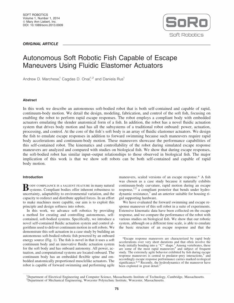
our approach in Ref.14 and again use an 8 g CO2 gas cylinder(PN 80121; Leland Ltd., Inc., South Plainfield, NJ) housingfluid at high pressure and low volume (Fig. 5A). In this form,a relatively large amount of fluidic energy can be stored in avolume suitable for storage onboard the robot.
The total potential energy stored within, E, and energydensity, D, of the high-pressure container can be theorized byassuming that the energy release is isothermal and by ne-glecting fluid phase changes,
D¼ E
V¼R vf
v0Ps(v) dv
V: (6)
Here, the supply pressure Ps is a nonlinear function ofvolume v, and this relation is defined using the Van der Waals
FIG. 3. Illustration of the soft fish body fabrication process. First, two halves of the body (1a), a connector piece (1b), anda constraining layer (1c) are all cast from silicone by two-part molds. Next, these four pieces are sequentially bondedtogether using a thin layer of silicone (2). Lastly, once cured, the fish body is ready for operation (3).
AUTONOMOUS SOFT ROBOTIC FISH CAPABLE OF ESCAPE MANEUVERS 79

gas law. The volume v0 is the fluid’s volume corresponding tothe vapor pressure of the gas, Ps(v0) = Pvapor. The volume vf isthe fluid’s volume at standard temperature and pressure. Thevolume occupied by the container is V. Table 3 contains ap-plication-specific parameters for the power supply. Accordingto Equation 6, the estimated energy density of this powersupply is 0.1 ( MJ
L), and the estimated total energy stored is 1.86
kJ. Although a typical lithium polymer battery has an energydensity of 0.9–1.5 ( MJ
L), electrical energy is not suitable for
directly powering FEAs; in such a case, the energy must firstbe converted to the fluid domain using supporting hardware,occupying additional volume and imposing energy losses. Thismotivates our use of a fluidic power supply.
Gas delivery
Both an onboard gas regulation mechanism{ shown in Figure5B and delivery system (Fig. 5C and D) are required to dis-tribute the stored fluid to the robot’s actuators. First, the fluid isregulated to a suitable driving pressure, Pd, an order of mag-nitude below supply pressure. Subsequently, gas flows througha series of control valves and into the body actuators. Thenetwork of valves and fluid pathways between the regulator andactuators resist fluid flow. Consequently, inlet flow Q to theactuators is driven byDP, the pressure gradient between Pd, andthe actuator’s internal pressure Pa. To ensure that Pd is ofsufficient magnitude to drive the body through its target kine-matic profile, a relationship between Q and DP is theorized.
From our analysis in Figure 4, inlet flows of between 30and 50 L/m are required for several hundred milliseconds.Within the gas delivery system, Reynolds numbers are inexcess of 3 · 104, above the critical Reynolds number of2.3 · 103, indicating turbulent flow. Assuming fully devel-oped turbulent flow as well as constant fluid density, vis-cosity, and temperature, we can estimate the DP required todrive Q as follows:
DP¼Pd�Pa¼ qghT (7)
where q is the fluid’s density, g the gravity, and hT the totalhead loss of the fluid delivery system, defined as,
hT¼ +n
i¼ 1
8Q2
p2d4i g
fiLi
di
þ +m
j¼ 1
Ki, j
!(8)
where i indexes the n serial pathways within the fluid de-livery system, L and d are the length and diameter of thepathway, Kj the loss coefficients of a pathway containing mlosses, and f the friction factor as defined by the Haalandequation.37
Specifically, we calibrate Equation 8 to characterize the caseof maximum excursion. Here, the anterior agonistic controlvalve is fully open, the antagonistic valve is fully occluded, andfor simplicity we ignore the posterior actuator pair. The fluidpathway has three main parts: (1) the section between the reg-ulator and valve orifice, (2) the valve, and (3) the valve to theactuator inlet. Pathways 1 and 3 are designed to minimize re-sistance and accordingly contribute little to hT. However, con-straints on valve performance and size force pathway 2 to be ofhigh resistance. Finite element analysis was used to estimatelosses (SK) (see Table 3 for parameter estimates). As a result ofthis analysis, DP is required to be between 0.06 and 0.10 MPa,and considering the range of Pa in Figure 4 and commercialavailability, a regulator providing a Pd of 0.29 MPa was chosen.
The above analysis suggests that the gas delivery system isresponsible for considerable resistive energy losses. Given ananterior actuator frequency of f, we can estimate the losses ofthis subsystem over a single bidirectional actuation cycle:EResistive¼ (Pd�Pa)Q 1
f: On the basis of experimental data
detailed in Figure 4, we can expect losses of around 50 J percycle while driving the anterior actuators during forwardswimming.
Processing and control
The robot contains an onboard microprocessor{ andwireless communication modulex that enable it to both pro-cess external inputs and execute control policies. This com-putational system interfaces directly with onboard hardwaresuch as control valves and any available sensors. Two pro-portional valves** are used to control the pressurization of
FIG. 4. Pressure–volume profiles of fluid used to fill theanterior agonist actuator at various flow rates. By integratingthe change in pressure as a function of displaced volume, theelastic and resistive components of work done on the actu-ator are determined.
Table 2. Elastic and Resistive Components
of Work Done on the Soft Body in Water
Massflow (L/m)
Totalwork (J)
Elasticwork (%)
Resistivework (%)
5 2.89 100 010 3.11 93.5 6.520 3.36 87.1 12.930 3.60 81.9 18.140 3.69 80.6 19.450 3.88 77.7 22.3
{0.29 MPa regulator (PN 50044; Leland Ltd., Inc.).
{Atmega 644P (Atmel Corporation, San Jose, CA).xXBee-PRO 900 (Digi International Inc., Minnetonka, MN).**PN 921-111051-000 (Parker Precision Fluidics).
80 MARCHESE ET AL.
the agonistic and antagonistic anterior actuators, and twoexhaust valves{{ control depressurization. Two solenoidvalves{{ control pressurization and depressurization of theposterior actuator pair. Depressurization of the body actua-tors is primarily passive. The exhaust and solenoid valveorifices resist fluid outflow, and the actuators act as fluidenergy storage devices, analogous to a capacitor in theelectrical domain. If we ignore the fluid’s negligible inertia,we can represent actuator depressurization as an undrivenfirst-order system, analogous to a capacitor dischargingthrough a resistor. The instant the exhaust valve is open, thepressure gradient driving exhaust flow is equal to Pa, and theflow is at a maximum. Subsequently, the flow exponentiallydrops to zero. Although the computational system can pro-vide onboard autonomy, the robot wirelessly communicateswith a host PC to receive user commands. The fish is nega-tively buoyant and held at a fixed submergence by means of afloating support.
The control policy of fully actuated fish locomotion can bedescribed using seven parameters, T1, M1, T2, M2, u, T3, andT4. The anterior control valves are driven using a square-wave input, and agonistic and antagonistic valves are ener-gized sequentially ensuring while one actuator is pressurizingthe other is exhausting. Here, T1 and T2 are the open periodsof the anterior agonistic and antagonistic actuator propor-tional control valves, respectively. The corresponding orificemagnitudes M1 and M2 of these control valves are defined as apercent of maximum available flow. The parameter u is thephase delay between the anterior and posterior actuator pairs,and T3 and T4 are the open periods of the posterior agonisticand antagonistic actuator control valves, respectively, andtheir magnitudes are fixed. However, the body can also bedriven as an underactuated system where fewer than the totalnumber of available actuators are used. For forward loco-motion, this abbreviated policy can be parameterized usingonly T1, M1, T2, and M2. For escape responses, this policy canbe further reduced to using only T1 and M1. During escaperesponses, the posterior agonistic actuator is also used, but T3
is set equal to T1.
Results
Locomotion
As mentioned, the fish’s body can function as an under-actuated system, where a single control input can excitemultiple modes of motion. Using just the anterior actuatorpair as opposed to all four available actuators for forwardswimming allows the fish to conserve the limited fluid energystored onboard. Similar to the work of Valdivia y Alvaradoand Youcef-Toumi,25 our fish can use anterior trunk actuatorsto excite movement in the entire compliant body, producingfast forward swimming. During the experiment detailed inFigure 6, the fish operated using an open-loop controller, andits objective was to swim in a straight line. Here, the posteriortrunk actuator pair was passive, the anterior trunk actuatorswere periodically driven at 1.67 Hz, and linear velocitiesof 150 mm/s, or 0.44 body lengths/s, were attained. Ap-proximately 30 tail beats were available from the 8 g CO2
cylinder under these experimental conditions. Forward lo-comotion performance parameters were measured using a
FIG. 5. Details of gas storage,regulation, and release mechanism.The mechanism consists of a high-pressure CO2 gas cylinder (A), apassive mechanical regulator (B),an interface manifold (C), propor-tional control valves (D), and ex-haust valves (E). On the left, redarrows illustrate gas flow duringactuator pressurization; on theright, black arrows illustrate gasflow during depressurization.
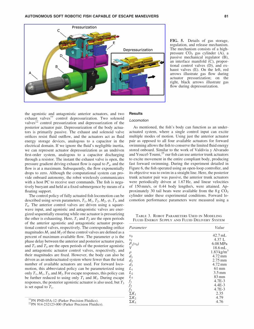
Table 3. Robot Parameters Used in Modeling
Fluid Energy Supply and Fluid Delivery System
Parameter Value
v0 42.7 mLvf 4.37 LPs(v0) 6.08 MPaV 18.6 mLq 1.83 kg/m3
d1 4.72 mmd2 2.75 mmd3 4.72 mmL1 61 mmL2 3.5 mmL3 83 mmf1 4.7E-3f2 4.4E-3f3 4.7E-3SK1 2.35SK2 4.79SK3 4.76
{{PN PND-05A-12 (Parker Precision Fluidics).{{PN 914-232123-000 (Parker Precision Fluidics).
AUTONOMOUS SOFT ROBOTIC FISH CAPABLE OF ESCAPE MANEUVERS 81

high-speed video camera and a mirror mounted at 45 degreesunderneath the robot. Video was recorded at 300 fps, and ninecolored points along the robot’s dorsal midline were digitizedduring postprocessing.
The forward-swimming results show that the self-contained actuation system is capable of sustained operation,exemplified by forward fishlike locomotion. However, theswimming gait we present here is certainly suboptimal. Acomprehensive sweep over driving pressures, tail frequen-cies, and body stiffness would allow optimization of forwardlocomotion.
Escape response
A critical behavior exhibited among fish is an escape re-sponse, which involves rapidly bending the fish’s body tolarge angles in order to accelerate away from adverse stimuli.
Experiments were conducted to investigate the escape re-sponse of our soft-bodied robotic fish and compare its ma-neuvers to that of natural fish. A total of 28 escape responseexperiments are reported and were carried out in a 76-cm-long by 76-cm-wide by 61-cm-tall water tank filled to 41 cm.The robot was completely submerged and held at an initialfixed submergence by means of a 172-cm-long nylon string.Escape responses were generated using an open-loop con-troller. Escape response performance parameters were mea-sured using the same high-speed videography techniques aslisted for the forward locomotion experiment; however, herethe camera was positioned overhead. Heading angle is de-fined in degrees as the rotational displacement of the rigidanterior midline. Escape angle is defined as the resultingheading angle after the maneuver when the angular rate dropsto zero. Linear escape velocity is defined as the Cartesianvelocity of the center of mass 500 ms after the onset of themaneuver.
Fish 30–40 cm in length (rainbow trout and northern pike)have been shown to perform type I, or single-bend, escaperesponses where the body initially bends into an ‘‘S’’ shapeand subsequently into a ‘‘C’’ shape with heading anglesgreater than 90 degrees.38 Our robot exhibits fishlike mech-anisms to accelerate (see the exemplary single-bend escaperesponse in Figures 7A–D and 8A). We create single-bendresponses by using only the anterior and posterior agonisticbody actuators. Here, from 0 to 150 ms the body’s midlineassumes an ‘‘S’’ shape with the caudal fin curving in theopposite direction of the trunk. From 150 to 500 ms thebody’s midline assumes a ‘‘C’’ shape as the caudal fin, pe-duncle region, and trunk exhibit the same direction of cur-vature. The robot reaches a maximum heading angle of 100degrees at approximately 520 ms. The aforementioned natu-ral fish also exhibit type II, or double-bend, escape responsescharacterized by the fish’s anterior region bending away fromthe posterior midline’s primary direction of curvature as thebody assumes a ‘‘C’’ shape.38 In Figures 7E–H and 8B, therobot performs a double-bend escape response using bothanterior and posterior agonistic and antagonistic body
FIG. 6. Experimental results of the robotic fish duringforward swimming. The top panel shows the digitized av-erage body midline position moving as a function of time.The bottom panel details the corresponding linear velocityof the center of mass as a function of time. During thisexperiment, tail stroke frequency is 1.67 Hz, and a velocityof approximately 150 mm/s is attained.
FIG. 7. Sequences depicting the soft robotic fish performing both a single-bend (A–D) and double-bend (E–H) escaperesponse. The single-bend response requires only agonistic actuator effort. The double-bend response requires sequentialagonistic and antagonistic actuator efforts, causing a significant decrease in heading angle and ultimately resulting in lowerescape angles than single-bend responses. Actuator effort durations of 160 ms were used in both escape responses.
82 MARCHESE ET AL.

FIG. 8. Escape response kinematics of the soft-bodied robotic fish. Panel (A) details kinematics of a typical single-bendescape response for the robotic fish; similarly, panel (B) details a double-bend escape response. The top portions of thepanels show the digitized body midline (red) overlaid every 10 ms from the first detectable motion to the end of maneuver.The middle portions show the corresponding angular velocity of the head along with actuator effort (agonistic is positive;antagonistic is negative). At the bottom is the resulting center-of-mass velocity for each maneuver.
AUTONOMOUS SOFT ROBOTIC FISH CAPABLE OF ESCAPE MANEUVERS 83

actuators. Here, the ‘‘C’’ shape is assumed at 170 ms and isquickly preceded by the body straightening. A maximumheading angle of 72 degrees is obtained at 410 ms. In general,the robotic fish exhibits higher escape angles in single-bendthan in double-bend escape responses. Figure 9 portrays botha single- and double-bend escape response of an angelfish(body length of 7.3 cm) exhibiting a similar kinematic patternto our robot; that is, the angelfish is also shown to have higherescape angles in single-bend than in double-bend re-sponses.39
Foreman and Eaton40 document that single-bend maneu-vers in fish result in higher escape angles and slower center-of-mass motion, while double-bend maneuvers result inlower escape angles and faster center-of-mass motion. Con-sequently, although antagonistic effort is not required forcenter-of-mass motion, it is responsible for amplifying thecenter-of-mass motion and a period of negative angular ratein natural fish. An important result is that our robot exhibitssimilar behavior: In double-bend responses, escape angle islower and linear escape velocity higher than in single-bendresponses. In double-bend escape responses having antago-nistic actuator activity (Fig. 8B), the escape angle is reduced,as there is significant angular rate in the negative (antagonistic)direction starting at approximately 380 ms (60 ms after the
completion of antagonistic activity). Onset of significantcenter-of-mass motion occurred at 160 ms, approximatelysynchronized with the onset of antagonistic activity.
A point of contrast is that in natural fish the head and tailboth move toward each other in the first stage of the escaperesponse (Fig. 9). However, because the center of mass of ourrobot is in the anterior head region, head movement isgreatest during the second stage of the escape response.
Eaton, Lee, and Foreman’s direction-change hypothesis innatural fish41 is consistent with the behavior of our roboticfish. Specifically, a combination of agonistic and antagonisticactuator inputs can independently influence both escapeangle and linear escape velocity during the robot’s escaperesponse. A series of experiments were carried out to inves-tigate the effect of two parameters, T1
xx and M2, on the escapeangle and linear escape velocity of the robotic fish (Fig. 10).As a result we found that T1 has marked influence on escapeangle. Mean escape angle at T1 equal to 100 ms was 26.6degrees, whereas mean escape angle was 81.4 degrees at T1,equal to 160 ms. Also, M2 provides control over escape angle.Increasing M2 decreased escape angle (Fig. 10A). Unlike
FIG. 9. Fast-start kinemat-ics of an angelfish. At the topis the body midline plottedfor a single-bend (A) and adouble-bend (B) fast-start. Atthe bottom is the corre-sponding angular velocityprofile for the double-bendfast-start. These figures arereproduced with permissionfrom Domenici and Blake39
and Domenici and Blake,1
respectively.
xxT1 = T2 in all tests.
84 MARCHESE ET AL.

escape angle, T1 has minimal influence on linear escape ve-locity, mean values of 193.1 and 207.2 mm/s for 100 and160 ms, respectively. However, M2 provided control overlinear escape velocity in that increasing effort level expo-nentially increased velocity (Fig. 10B). These findings indi-cate that through a combination of agonistic and antagonisticactuator efforts, escape angle and linear escape velocity canbe independently altered. Given a fixed maximal agonisticeffort level, altering T1 and M2 can independently influenceboth the resulting escape angle and escape velocity.
Discussion
The robotic fish provides an instantiation of our approachto creating autonomous soft-bodied robots capable of rap-idly achieving continuum-body motion. In this system, soft
musclelike actuators generate curvature in a continuouslydeformable, vertebrate-like body. Novel, form-independentactuator technology as well as miniaturization of supportinghardware enable the robot to take on the fundamental ana-tomical structure of a fish while being self-contained andunconstrained.
The programmability of our system allows repeatableevaluation of the robot’s escape response maneuvers. Bydirectly controlling the duration and magnitude of agonisticand antagonistic actuator efforts and measuring the resultingescape response performance, we conclude that agonisticduration has strong authority over escape angle and minimalauthority over linear escape velocity. Antagonistic magni-tude has nonlinear control authority over both escape angleand escape velocity. Increasing agonistic effort duration al-lows for greater angular displacement of the head to bereached during the first stage of the response. Soon after thisduration of time, the robot’s head begins to decelerate. Thelonger the agonistic effort is applied, the greater the escapeangle. When antagonistic effort magnitude increases, there ismore energy to decelerate the turn and consequently escapeangle lowers. The antagonistic effort also provides the pro-pulsive stroke, so greater antagonistic effort yields higherescape velocity.
Evidence suggests that a similar input–output relationshipholds in biological escape response behavior. Consistent withour robotic system, Foreman and Eaton40 presented the di-rection change concept, where they show that escape re-sponse heading angle is a function of the relative magnitudesand timings of agonist and antagonist muscle contractions.Wohl and Schuster42 investigated the predictive start ofhunting archer fish and showed that in the underlying C-startbehavior, escape angle and escape velocity need to be de-coupled. Also in line with our robotic system, Tytell andLauder43 found that, among investigated variables, stage-oneduration correlated most strongly with escape angle and thatantagonistic effort magnitude correlated most strongly withescape velocity in biological fish.
Our findings also suggest that despite the apparent com-plexity of the maneuver, it is feasible that a robotic systemwith limited onboard computational power could determinerequired escape response control parameters in real time andwith no a priori planning. Because the robot’s escape re-sponse performance outputs, angle and velocity, are inher-ently decoupled by the physical form of the body andstructure of the maneuver, control parameters could poten-tially be computed onboard. For instance, the maneuver maystart in immediate response to a perceived external stimuluswith a predetermined maximal agonistic effort. As this effortoccurs, the desired escape angle and velocity may be com-puted relative to the perceived stimuli. Accordingly, thecontrol variables T1 and M2 can be determined given amapping similar to that provided in Figure 10.
Acknowledgments
A special thanks to Robert Katzschmann from the Dis-tributed Robotics Laboratory and the Soft Robotics reviewersfor their extensive feedback. This work was done in theDistributed Robotics Laboratory at MIT with support fromthe National Science Foundation (grant numbers NSFIIS1226883 and NSF CCF1138967) and National Science
FIG. 10. Input–output relationship of escape responsemaneuvers in the robotic fish. (A) Escape angle as a functionof antagonistic actuator effort. (B) Escape velocity as afunction of antagonistic actuator effort. In both cases, equalduration agonistic and antagonistic efforts of 100 and160 ms were used (blue and red lines, respectively). Datapoints represent mean values (n = 4 and n = 3 for 100 and160 ms scenarios, respectively, for a total of 28 tests), anderror bars represent standard deviations.
AUTONOMOUS SOFT ROBOTIC FISH CAPABLE OF ESCAPE MANEUVERS 85

Foundation Graduate Research Fellowship Program (primaryaward number 1122374). We are grateful for this support.
Author Disclosure Statement
The authors declare no competing financial interests exist.
References
1. Domenici P, Blake RW. The kinematics and performance offish fast-start swimming. J Exp Biol 1997;200:1165–1178.
2. Borazjani I, Sotiropoulos F, Tytell ED, Lauder GV. Hy-drodynamics of the bluegill sunfish C-start escape response:three-dimensional simulations and comparison with ex-perimental data. J Exp Biol 2012;215:671–684.
3. Wakeling JM, Johnston IA. Body bending during fast-startsin fish can be explained in terms of muscle torque andhydrodynamic resistance. J Exp Biol 1999;202:675–682.
4. Jayne BC, Lauder GV. Red and white muscle activityand kinematics of the escape response of the bluegillsunfish during swimming. J Comp Physiol A 1993;173:495–508.
5. Webb PW, Skadsen JM. Strike tactics of Esox. Can J Zool1980;58:1462–1469.
6. Walker JA, Ghalambor CK, Griset OL, McKenney D,Reznick DN. Do faster starts increase the probability ofevading predators? Funct Ecol 2005;19:808–815.
7. Gibb AC, Swanson BO, Wesp HM, Landels C, Liu C.Development of the escape response in teleost fishes: doontogenetic changes enable improved performance? PhsiolBiochem Zool 2006;79:7–19.
8. Domenici P, Turesson H, Brodersen J, Bronmark C. Pre-dator-induced morphology enhances escape locomotion incrucian carp. Proc R Soc Ser B 2008;275:195–201.
9. Bergstrom CA. Fast-start swimming performance and re-duction in lateral plate number in threespine stickleback.Can J Zool 2002;80:207–213.
10. Shepherd RF, Ilievski F, Choi W, Morin SA, Stokes AA,Mazzeo AD, Chen X, Wang M, Whitesides GM. Multigaitsoft robot. Proc Natl Acad Sci USA 2011;108:20400–20403.
11. Shepherd RF, Stokes AA, Freake J, Barber J, Snyder PW,Mazzeo AD, Cademartiri L, Morin SA, Whitesides GM.Using explosions to power a soft robot. Angew Chem2013;125:2964–2968.
12. Onal CD, Rus D. Autonomous undulatory serpentine lo-comotion utilizing body dynamics of a fluidic soft robot.Bioinspir Biomim 2013;8:026003.
13. Onal CD, Chen X, Whitesides GM, Rus D. Soft mobilerobots with on-board chemical pressure generation. Inter-national Symposium on Robotics Research (ISRR), Flag-staff, AZ, August 28–September 1, 2011.
14. Marchese AD, Onal CD, Rus D. Towards a self-containedsoft robotic fish: on-board pressure generation and em-bedded electro-permanent magnet valves. Exp Rob 2013;88:41–54.
15. Liu J, Hu H. Biological inspiration: from carangiform fishto multi-joint robotic fish. J Bionic Eng 2010;7:35–48.
16. Barrett DS, Triantafyllou MS, Yue DKP, Wolfgang MJ,Grosenbaugh MA. Drag reduction in fish-like locomotion. JFluid Mech 1999;392:183–212.
17. Triantafyllou M, Triantafyllou G. An efficient swimmingmachine. Sci Am 1995;272:64–70.
18. Zhong Y, Chong CW, Zhou C, Seet G, Low KH. Perfor-mance predict model for a body and caudal fin (bcf) bio-
mimetics fish robot. IEEE/ASME International Conferenceon, July 14–17, 2009. Adv Intell Mechatronics 2009;1230–1235.
19. Wen L, Wang TM, Wu GH, Liang JH. Hydrodynamic in-vestigation of a self-propelled robotic fish based on a force-feedback control method. Bioinspir Biomim 2012;7:036012.
20. Lui J, Hu H. Mimicry of sharp turning behaviours in arobotic fish. Proceedings of the 2005 IEEE InternationalConference on Robotics and Automation (ICRA), 2005.
21. Xu JX, Ren Q, Gao W, Niu XL. Mimicry of fish swimmingpatterns in a robotic fish. 2012 IEEE International Sym-posium on Industrial Electronics (ISIE), 2012.
22. Su Z, Yu J, Tan M, Zhang J. A closed-loop method togenerate fast C-start for a robotic fish. 2011 InternationalConference on Mechatronics and Automation (ICMA),Beijing, China, 2011.
23. Lauder GV, Flammang B, Alben S. Passive robotic modelsof propulsion by the bodies and caudal fins of fish. IntegrComp Biol 2012;52:576–587.
24. Alben S, Witt C, Baker TV, Anderson E, Lauder GV.Dynamics of freely swimming flexible foils. Phys Fluids2012;24:38–62.
25. Valdivia y Alvarado P, Youcef-Toumi K. Design of ma-chines with compliant bodies for biomimetic locomotionin liquid environments. J Dyn Sys Meas Control 2006;128:1–2.
26. El Daou H, Salumae T, Toming G, Kruusmaa M. Bio-inspired compliant robotic fish: design and experiments.IEEE International Conference on Robotics and Automa-tion (IEEE ICRA 2012), St. Paul, Minnesota, 2012.
27. El Daou H, Salumae T, Ristolainen A, Toming G, ListakM, Kruusmaa M. A bio-mimetic design and control of afish-like robot using compliant structures. The 15th IEEEInternational Conference on Advanced Robotics (ICAR2011), Tallinn, 2011.
28. Feng C, Bonafilia BR, Modarres-Sadeghi Y, TriantafyllouMS. The mechanics of fast-start performance of pikestudied using a mechanical fish. Proceedings of the ASME2011 International Mechanical Engineering Congress &Exposition IMECE2011, Denver, Colorado, 2011.
29. Long JH, Koob T, Schaefer J, Summers A, Bantilan K,Grotmol S, Porter M. Inspired by sharks: a biomimeticskeleton for the flapping, propulsive tail of an aquatic robot.Mar Technol Soc J 2011;45:119–129.
30. Long JH, Krenitsky NM, Roberts SF, Hirokawa J, deLeeuw J, Porter ME. Testing biomimetic structures inbioinspired robots: how vertebrae control the stiffness ofthe body and the behavior of fish-like swimmers. IntegrComp Biol 2011;51:158–175.
31. Shen Q, Wang T, Liang J, Wen L. Hydrodynamic perfor-mance of a biomimetic robotic swimmer actuated by ionicpolymer–metal composite. Smart Mater Struct 2013;22:075035.
32. Festo. Airacuda, 2006. Available at: www.festo.com/cms/en_corp/9761.htm (accessed Dec. 31, 2013).
33. Correll N, Onal CD, Liang H, Schoenfeld E, Rus D. Softautonomous materials—using active elasticity and embed-ded distributed computation. Springer Tracts Adv Rob2014;79:227–240.
34. Marchese AD, Onal CD, Rus D. Soft robot actuators usingenergy-efficient valves controlled by electropermanentmagnets. IEEE/RSJ International Conference on IntelligentRobots and Systems (IROS), San Francisco, CA, 2011.
86 MARCHESE ET AL.

35. Spierts IL, Van Leeuwen JL. Kinematics and muscle dy-namics of c-start and s-starts of carp (Cyprinus carpio l.). JExp Biol 1999;202:393–406.
36. Otis AB. The work of breathing. Physiol Rev 1954;34:449–458.
37. Haaland SE. Simple and explicit formulas for the frictionfactor in turbulent. J Fluids Eng 1983;105:8990.
38. Harper DG, Blake RW. Fast-start performance of rainbowtrout Salmo gairdneri and northern pike Esox lucius. J ExpBiol 1990;150:321–342.
39. Domenici P, Blake RW. The kinematics and performanceof the escape response in the angelfish (Pterophyllum ei-mekei). J Exp Biol 1991;156:187–205.
40. Foreman MB, Eaton RC. The direction change concept forreticulospinal control of goldfish escape. J Neurosci 1993;13:4101–4113.
41. Eaton RC, Lee RKK, Foreman MB. The Mauthner cell andother identified neurons of the brainstem escape network offish. Prog Neurobiol 2001;63:467–485.
42. Wohl S, Schuster S. The predictive start of hunting archerfish: a flexible and precise motor pattern performed with thekinematics of an escape C-start. J Exp Biol 2007;210:311–324.
43. Tytell ED, Lauder GV. The C-start escape response ofPolypterus senegalus: bilateral muscle activity and vari-ation during stage 1 and 2. J Exp Biol 2002;205:2591–2603.
Address correspondence to:Andrew D. Marchese
Department of Electrical Engineeringand Computer Science
Massachusetts Institute of Technology32 Vassar Street, Room 32-376
Cambridge, MA 02139
E-mail: [email protected]
AUTONOMOUS SOFT ROBOTIC FISH CAPABLE OF ESCAPE MANEUVERS 87