automated visual inspection for automotive flat …...automated visual inspection for automotive...
TRANSCRIPT

1 S E E T H E D I F F E R E N C E
© 2015 Radiant Vision Systems, LLC. All Rights Reserved.
AUTOMATED VISUAL INSPECTION FOR
AUTOMOTIVE FLAT PANEL DISPLAYS
Douglas Kreysar
Chief Solutions Officer
October 24, 2014

2 S E E T H E D I F F E R E N C E
© 2015 Radiant Vision Systems, LLC. All Rights Reserved.
OUTLINE
• FPD quality now critical to model
purchase and referral
• Automated Test Methods for
illuminated FPDs are well-
established
quantitative, objective, repeatable
can point to root causes, quality improvement
• Automated testing is now extended
to cover non-lit or cosmetic defects
• Together, these methods can
improve quality and reduce the
negative impacts of “escapes”

3 S E E T H E D I F F E R E N C E
© 2015 Radiant Vision Systems, LLC. All Rights Reserved.
DISPLAY QUALITY DRIVES THE SALE
• For modern buyers, functionality of electronics may surpass the
appearance, NVH and performance of the car
• Display readability, clarity, brightness, color and contrast will be
judged against the latest phablets, laptops and TVs
• High resolution and a wide range of color/contrast make display
defects harder to detect
4 S E E T H E D I F F E R E N C E
© 2015 Radiant Vision Systems, LLC. All Rights Reserved.
PROPER TESTING PRECLUDES “ESCAPES”
• An “escape“ is a defective product that has found its way
to the consumer
• The negative consequences of an escape include: • On the showroom floor, a discovered defect can de-rail a sale
• After the sale, replacing a display can be time consuming and expensive
• That repair may spoil the owner’s experience with your brand
• That owner, through the miracle of the www, can put others off your
brand
• Just as easily, a perfect display can result in a satisfied
customer and endorsement of your brand.
5 S E E T H E D I F F E R E N C E
© 2015 Radiant Vision Systems, LLC. All Rights Reserved.
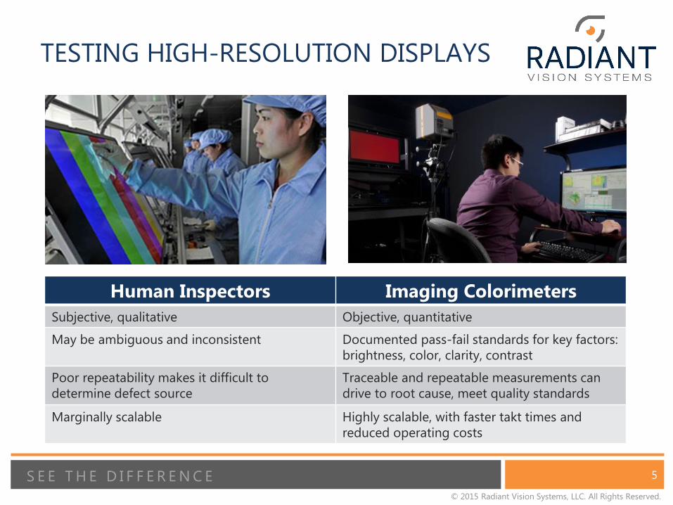
TESTING HIGH-RESOLUTION DISPLAYS
Human Inspectors Imaging Colorimeters
Subjective, qualitative Objective, quantitative
May be ambiguous and inconsistent Documented pass-fail standards for key factors:
brightness, color, clarity, contrast
Poor repeatability makes it difficult to
determine defect source
Traceable and repeatable measurements can
drive to root cause, meet quality standards
Marginally scalable Highly scalable, with faster takt times and
reduced operating costs
6 S E E T H E D I F F E R E N C E
© 2015 Radiant Vision Systems, LLC. All Rights Reserved.
MURA
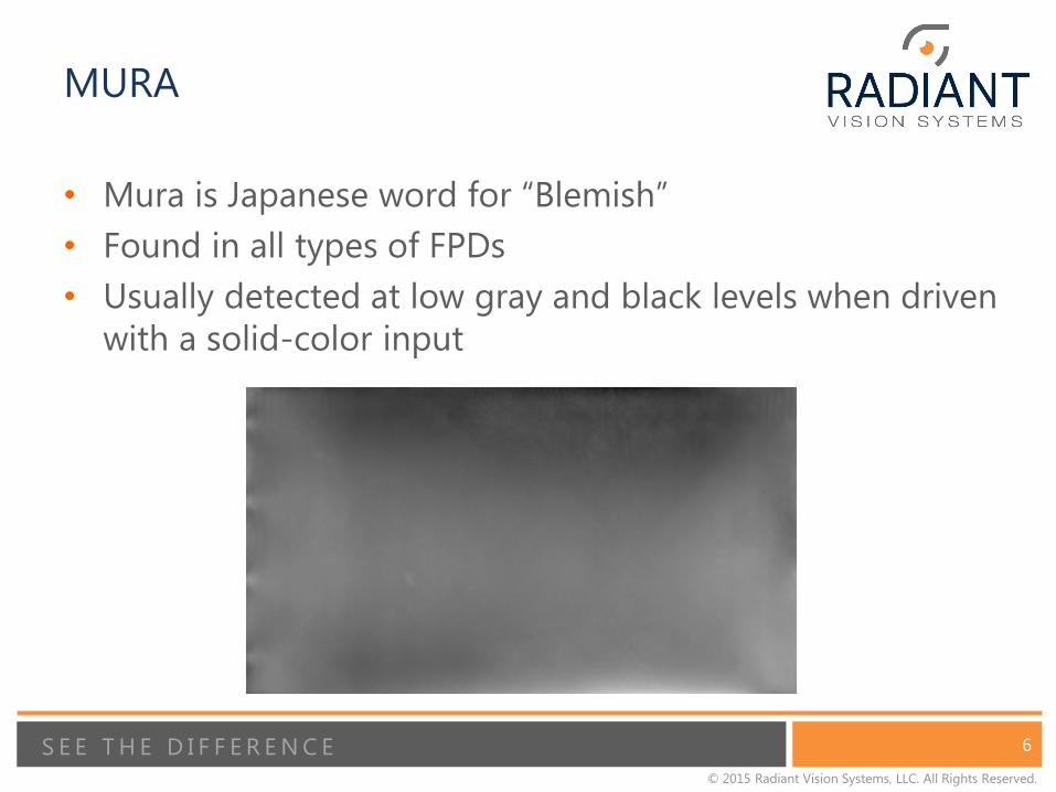
• Mura is Japanese word for “Blemish”
• Found in all types of FPDs
• Usually detected at low gray and black levels when driven
with a solid-color input
7 S E E T H E D I F F E R E N C E
© 2015 Radiant Vision Systems, LLC. All Rights Reserved.
MURA DETECTION
• Multiple methods have been used to detect Mura in Flat
Panel Displays:
• edge detection
• calculating gradients in the image
• contrasts against a background luminance
• color / brightness differences from nearby locations / averages
• This presentation will discuss two techniques:
• Spatial Standard Observer
• SEMU
8 S E E T H E D I F F E R E N C E
© 2015 Radiant Vision Systems, LLC. All Rights Reserved.
SPATIAL STANDARD OBSERVER
• A model of human contrast sensitivity with respect to
spatial frequencies
• Describes systems and techniques for processing visual
information
• Matches human visual perception
• Produces a numerical value, Just Noticeable Difference, as
a visibility metric
• Embodied in U.S. Patent 7,783,130, derived from research
at N.A.S.A.
• Makes possible the accuracy and repeatability of an
automated system
• Offers a powerful weapon for identifying and quantifying
perceptible Mura

9 S E E T H E D I F F E R E N C E
© 2015 Radiant Vision Systems, LLC. All Rights Reserved.
SPATIAL STANDARD OBSERVER
MODEL
The difference 3 between test image 1 and reference image 2 is filtered
by a constant sensitivity function 4, windowed by an aperture function 5,
and pooled non-linearly over space 6 to yield Just Noticeable Difference
(JND) metrics 7.
Information Display, January 2007, Vol. 23, No. 1, “The Spatial Standard Observer: A new tool for display metrology”, by Andrew B. Watson (NASA).
1
2
3
4 5 6
7
10 S E E T H E D I F F E R E N C E
© 2015 Radiant Vision Systems, LLC. All Rights Reserved.
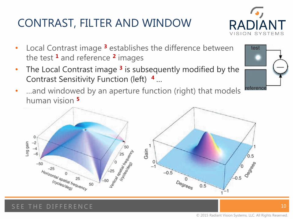
CONTRAST, FILTER AND WINDOW
• Local Contrast image 3 establishes the difference between
the test 1 and reference 2 images
• The Local Contrast image 3 is subsequently modified by the
Contrast Sensitivity Function (left) 4 …
• …and windowed by an aperture function (right) that models
human vision 5

11 S E E T H E D I F F E R E N C E
© 2015 Radiant Vision Systems, LLC. All Rights Reserved.
Black Mura test image 1 captured with an imaging colorimeter
Defect identified in
software, displayed in
Local Contrast view 3
Just Noticeable Defects 7
quantified, compared with
pass / fail criteria
SSO DEMONSTRATED ON BLACK MURA
12 S E E T H E D I F F E R E N C E
© 2015 Radiant Vision Systems, LLC. All Rights Reserved.
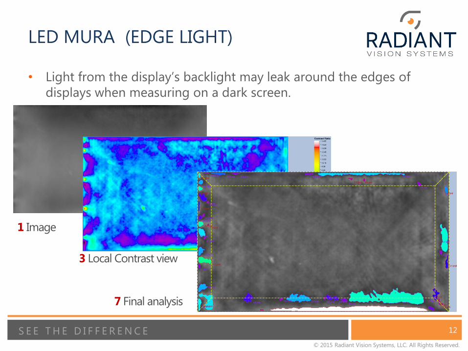
LED MURA (EDGE LIGHT)
• Light from the display’s backlight may leak around the edges of
displays when measuring on a dark screen.
1 Image
3 Local Contrast view
7 Final analysis
13 S E E T H E D I F F E R E N C E
© 2015 Radiant Vision Systems, LLC. All Rights Reserved.
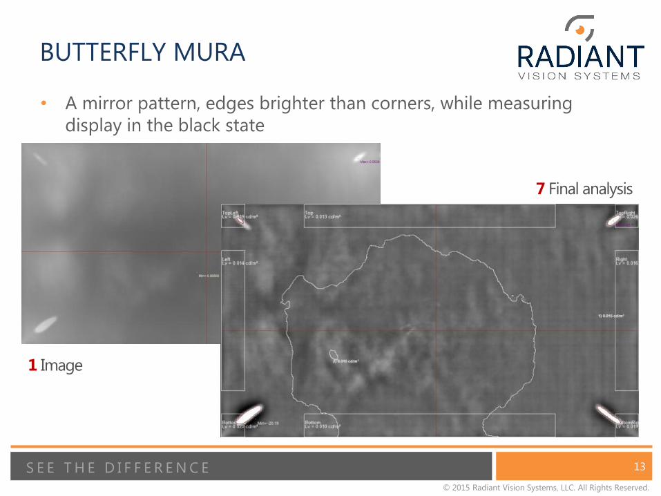
BUTTERFLY MURA
• A mirror pattern, edges brighter than corners, while measuring
display in the black state
1 Image
7 Final analysis
14 S E E T H E D I F F E R E N C E
© 2015 Radiant Vision Systems, LLC. All Rights Reserved.
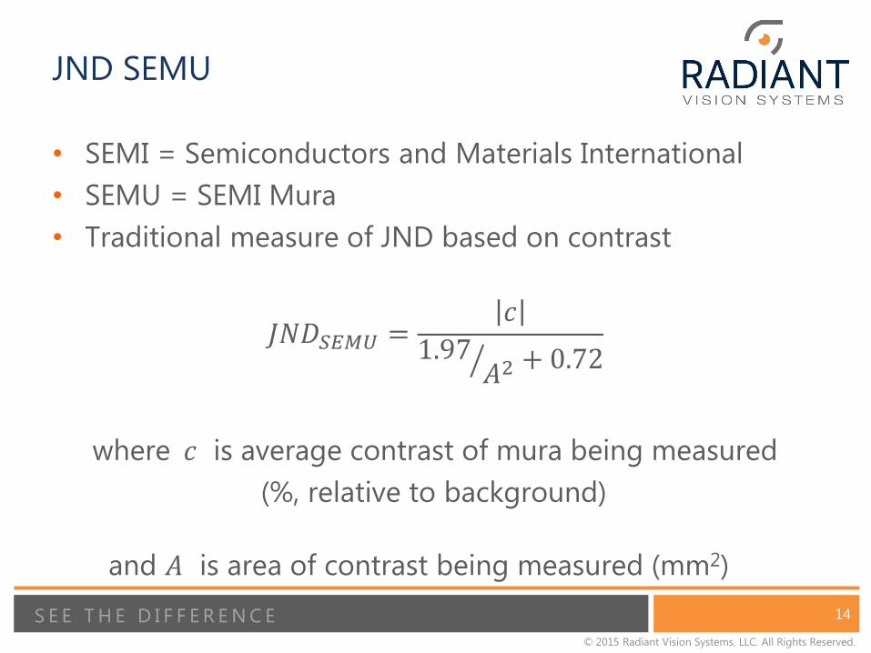
JND SEMU
• SEMI = Semiconductors and Materials International
• SEMU = SEMI Mura
• Traditional measure of JND based on contrast
𝐽𝑁𝐷𝑆𝐸𝑀𝑈 =𝑐
1.97𝐴2 + 0.72
where 𝑐 is average contrast of mura being measured
(%, relative to background)
and 𝐴 is area of contrast being measured (mm2)

15 S E E T H E D I F F E R E N C E
© 2015 Radiant Vision Systems, LLC. All Rights Reserved.
PARTICLE DEFECTS
• Particle Defects are very small blemishes on the display. These can
be the result of dust or defective pixels present in the display
Test Image
Final analysis
16 S E E T H E D I F F E R E N C E
© 2015 Radiant Vision Systems, LLC. All Rights Reserved.
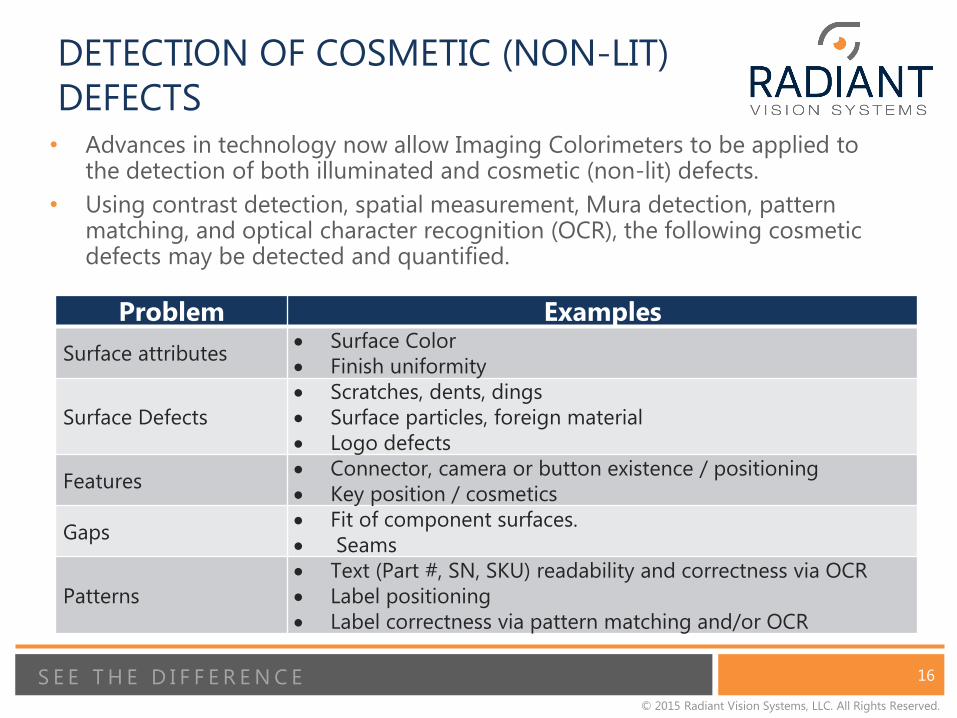
Problem Examples
Surface attributes Surface Color
Finish uniformity
Surface Defects
Scratches, dents, dings
Surface particles, foreign material
Logo defects
Features Connector, camera or button existence / positioning
Key position / cosmetics
Gaps Fit of component surfaces.
Seams
Patterns
Text (Part #, SN, SKU) readability and correctness via OCR
Label positioning
Label correctness via pattern matching and/or OCR
• Advances in technology now allow Imaging Colorimeters to be applied to the detection of both illuminated and cosmetic (non-lit) defects.
• Using contrast detection, spatial measurement, Mura detection, pattern matching, and optical character recognition (OCR), the following cosmetic defects may be detected and quantified.
DETECTION OF COSMETIC (NON-LIT)
DEFECTS

17 S E E T H E D I F F E R E N C E
© 2015 Radiant Vision Systems, LLC. All Rights Reserved.
SURFACE DEFECTS: SCRATCH
• Scratches (and dents, particles ,inclusions) are identified based on their
contrast. The values shown are contrast ratios relative to a background level.

18 S E E T H E D I F F E R E N C E
© 2015 Radiant Vision Systems, LLC. All Rights Reserved.
SURFACE DEFECTS: DENT
• The defect’s intensity, length and width can be measured and used to
determine whether a product passes or fails.
19 S E E T H E D I F F E R E N C E
© 2015 Radiant Vision Systems, LLC. All Rights Reserved.
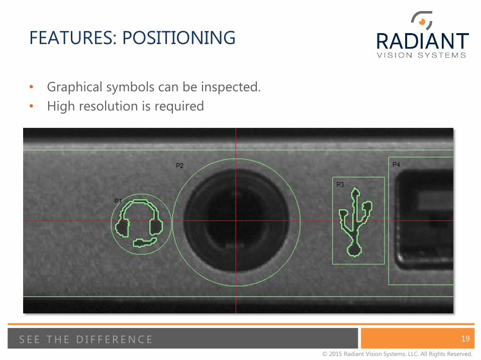
FEATURES: POSITIONING
• Graphical symbols can be inspected.
• High resolution is required

20 S E E T H E D I F F E R E N C E
© 2015 Radiant Vision Systems, LLC. All Rights Reserved.
GAPS
• Distances between high contrast areas are measured as
gaps.
• Physical gaps are important to discover and quantify on
the production line.
inches Pass Fail
Max. gap .053 .050
Min. gap .044 .024
Avg. gap .047 .039
Uniformity 83% 47%

21 S E E T H E D I F F E R E N C E
© 2015 Radiant Vision Systems, LLC. All Rights Reserved.
PATTERNS
OCR
• Text printed on the unit under test or on a label can be read by the camera
and OCR software.
• Serial numbers can be read from printed text or from a barcode.
22 S E E T H E D I F F E R E N C E
© 2015 Radiant Vision Systems, LLC. All Rights Reserved.
DISPLAY STACK-UP ISSUES
• A typical FPD is a vertical stack of Backlight Unit, LED and
various touch-sense / cover films.
• A defect in any element of the stack can result in a failure A particle in a cover film may appear in final display as a dead pixel
A defect in a Backlight Unit may reveal itself as color non-uniformity
A cosmetic gap in a stack-up layer might cause Mura or prevent assembly
• Sunk costs grow as stack assembly proceeds. Performing
cosmetic inspections of layers as a prerequisite to final
assembly can prevent shipping a defective display or
rejecting an expensive, completed display
23 S E E T H E D I F F E R E N C E
© 2015 Radiant Vision Systems, LLC. All Rights Reserved.
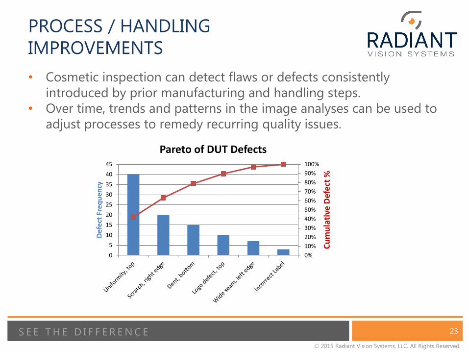
PROCESS / HANDLING
IMPROVEMENTS
• Cosmetic inspection can detect flaws or defects consistently
introduced by prior manufacturing and handling steps.
• Over time, trends and patterns in the image analyses can be used to
adjust processes to remedy recurring quality issues.
0%
10%
20%
30%
40%
50%
60%
70%
80%
90%
100%
0
5
10
15
20
25
30
35
40
45
Cu
mu
lati
ve D
efe
ct %
Def
ect
Freq
uen
cy
Pareto of DUT Defects

24 S E E T H E D I F F E R E N C E
© 2015 Radiant Vision Systems, LLC. All Rights Reserved.
CONCLUSIONS
• To make the sale and build the brand, perfect displays are required. “Escapes” must be avoided.
• New technology is available to support automated display testing for both illuminated and cosmetic (non-lit) defects.
• The resulting quantifiable test processes can drive process improvements, ensure display quality and deliver a favorable customer experience.

25 S E E T H E D I F F E R E N C E
© 2015 Radiant Vision Systems, LLC. All Rights Reserved.
For more information, email:
www.RadiantVisionSystems.com