article reprint courtesy of the turbo...
TRANSCRIPT
ARTICLE REPRINT COURTESY OF THE TURBO DIESEL REGISTER
60 www.turbodieselregister.com TDR 56
It has been duly noted that the TDR has reprinted material from previous magazines. Deciding when this practice is appropriate and timely is a difficult task--darned if you do, darned if you don’t.
From time to time we will crank up the “way-back machine” and repeat material that is relevant for present consideration. For this issue I went back to several old TDR magazines to revisit the topic of fuel transfer pumps.
I HATE TO DO THIS—FUEL TRANSFER PUMPS REVISITED
As the deadline for Issue 56 was fast approaching, I called TDR writer Jim Anderson. Jim is the point guy for miscellaneous e-mail and phone inquiries that come into the TDR. I asked, “Hey Jim, what’s on the minds of those that you are corresponding with?” His response, “It seems that problems with the Third Generation trucks vary. There is not a common complaint that needs to be addressed.” This is good news for the Third Generation crowd.
Jim continued, “However, with the used truck purchase of ’98.5-’02 vehicles the education about fuel transfer pumps is an endless task.” I responded, “Ouch, I know what you mean. Perhaps I should emulate the country music singer David Allen Coe’s efforts to write the perfect country music song by writing the perfect transfer pump article.” Jim responded, “Keep it simple, try the catch phrase from the Millionaire show ‘Is that your final answer?’”
Thus, I present the final-answer, perfect transfer pump article. While the article focuses on the ’98.5-’02 owners, this collection of TDR oldies also has tips for ’94-’98 12-valve owners and ’03-’07 HPCR owners. The information was pulled from our Issue 32, 48, and 50 magazines. Updates have been added to reflect the latest part number information.
Then, to add a final crescendo to the article, I’ll share with you a story that will be of interest to 300,000+ owners of ’03 and ’04.5 HPCR owners.
Below is an outline of the topics that will be covered.• ’98.5-’02 trucks, correct fuel pressure• ‘94-’98 12-valve, fuel transfer pump replacement• ‘98.5-’02 24-valve, fuel transfer pump replacement• Fuel pressure gauges and opinions• ‘98.5-’02 24-valve, fuel transfer pump relocation kit• ‘98.5-’02 24-valve, what to do• ‘03-’04.5 HPCR, what to do• ‘05 to current HPCR, what to do
Here we go…
CORRECT FUEL PRESSURE— ‘98.5-’02 TRUCKS
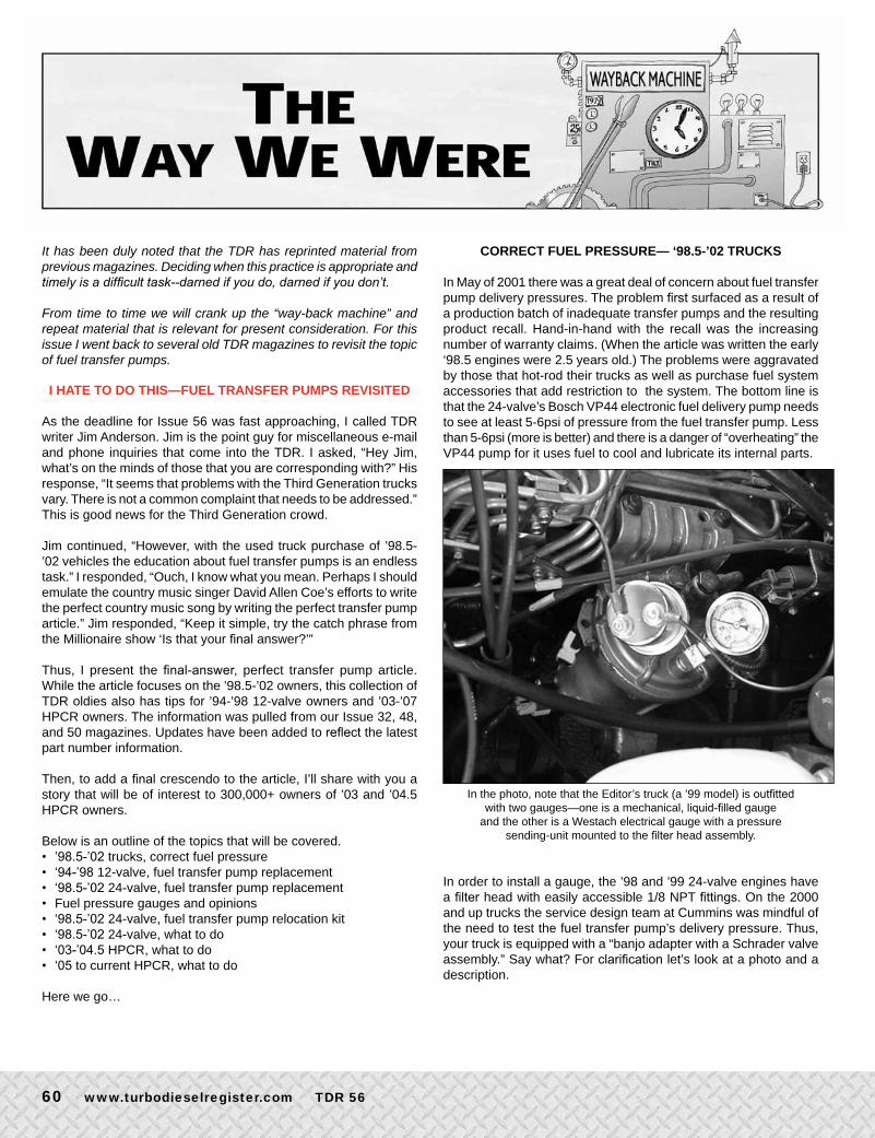
In May of 2001 there was a great deal of concern about fuel transfer pump delivery pressures. The problem first surfaced as a result of a production batch of inadequate transfer pumps and the resulting product recall. Hand-in-hand with the recall was the increasing number of warranty claims. (When the article was written the early ‘98.5 engines were 2.5 years old.) The problems were aggravated by those that hot-rod their trucks as well as purchase fuel system accessories that add restriction to the system. The bottom line is that the 24-valve’s Bosch VP44 electronic fuel delivery pump needs to see at least 5-6psi of pressure from the fuel transfer pump. Less than 5-6psi (more is better) and there is a danger of “overheating” the VP44 pump for it uses fuel to cool and lubricate its internal parts.
In the photo, note that the Editor’s truck (a ’99 model) is outfitted with two gauges—one is a mechanical, liquid-filled gauge
and the other is a Westach electrical gauge with a pressure sending-unit mounted to the filter head assembly.
In order to install a gauge, the ’98 and ’99 24-valve engines have a filter head with easily accessible 1/8 NPT fittings. On the 2000 and up trucks the service design team at Cummins was mindful of the need to test the fuel transfer pump’s delivery pressure. Thus, your truck is equipped with a “banjo adapter with a Schrader valve assembly.” Say what? For clarification let’s look at a photo and a description.
TDR 56 www.turbodieselregister.com 61
THE WAY WE WERE . . . . Continued
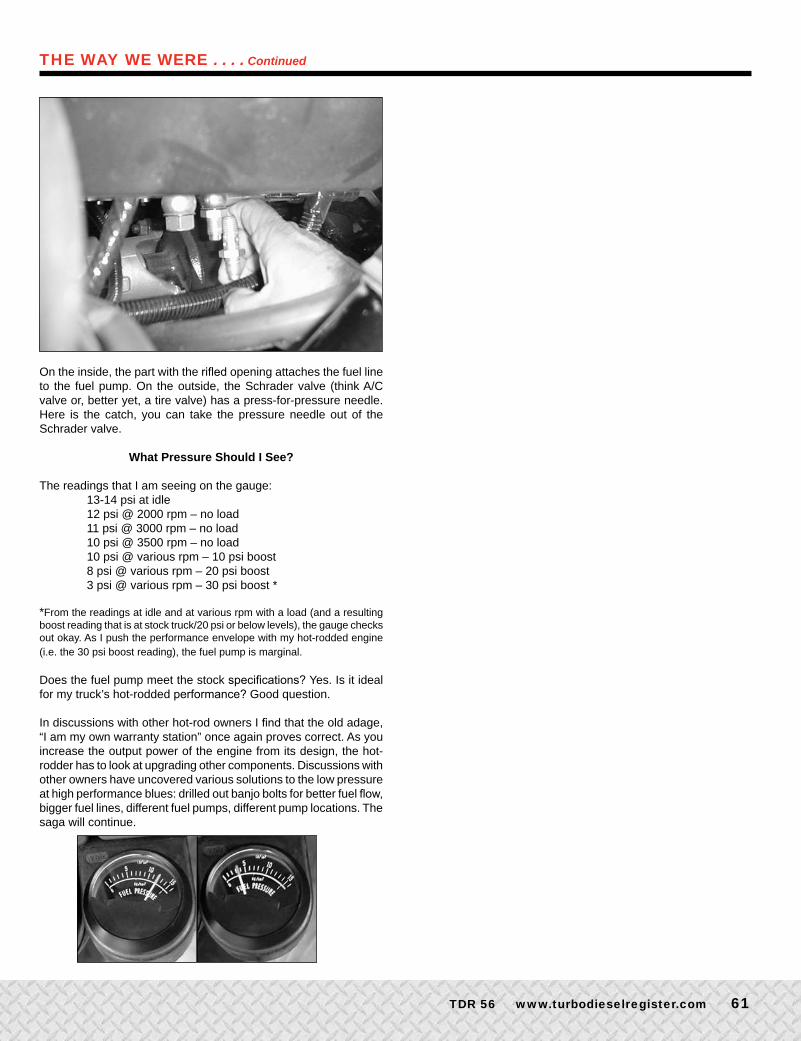
On the inside, the part with the rifled opening attaches the fuel line to the fuel pump. On the outside, the Schrader valve (think A/C valve or, better yet, a tire valve) has a press-for-pressure needle. Here is the catch, you can take the pressure needle out of the Schrader valve.
What Pressure Should I See?
The readings that I am seeing on the gauge: 13-14 psi at idle 12 psi @ 2000 rpm – no load 11 psi @ 3000 rpm – no load 10 psi @ 3500 rpm – no load 10 psi @ various rpm – 10 psi boost 8 psi @ various rpm – 20 psi boost 3 psi @ various rpm – 30 psi boost *
*From the readings at idle and at various rpm with a load (and a resulting boost reading that is at stock truck/20 psi or below levels), the gauge checks out okay. As I push the performance envelope with my hot-rodded engine (i.e. the 30 psi boost reading), the fuel pump is marginal.
Does the fuel pump meet the stock specifications? Yes. Is it ideal for my truck’s hot-rodded performance? Good question.
In discussions with other hot-rod owners I find that the old adage, “I am my own warranty station” once again proves correct. As you increase the output power of the engine from its design, the hot-rodder has to look at upgrading other components. Discussions with other owners have uncovered various solutions to the low pressure at high performance blues: drilled out banjo bolts for better fuel flow, bigger fuel lines, different fuel pumps, different pump locations. The saga will continue.
Maximum HP = “Cool Power” Air
Intake Systems for ’95 –’07.5 Dodge
2nd Gen Truck Cold Air Intake Duct
Now Available
Retains
Stock
“Sealed”
Air Box
Only kit that uses 100% outside air to
provide cool intake air to the turbo
■ More HP and Torque
■ Reduces Intake Restriction
■ 7-9° Lower Intake Air Temp
■ Decreases EGTs
Visit Our Website for 3rd
More Technical Info Gen
Performance Systems Manufacturing LLC www.psmbuick.com
(303) 279 - 7103 Pete Tomka (303) 885 - 4418 cell
62 www.turbodieselregister.com TDR 56
FROM ISSUE 40: ’94 to ’98 12-VALVE FUEL TRANSFER PUMP REPLACEMENT
by Brandon Parks I did not think fuel transfer pumps on 12-valve engines were a problem. I recall reading the “Backfire” column in Issue 39, where the editor states, “The old 12-valve engines used a mechanical fuel pump (the type driven off the engine’s camshaft) which is essentially problem free.” Nevertheless, as I started to read more about the transfer pump for 12-valve engines on the TDR website, it became obvious that there are many instances of pump failure. Is this something that we 12-valve owners should be watching out for?
Warning Signs
The first sign suggesting that my pump might be failing was very hard startups in the morning. Then I noticed that the idle rpm was slowly getting lower and when driving the truck it had lost its pep. Finally, the truck just wouldn’t start. After running a fuel pressure test to determine the problem, I concluded that it was the fuel lift pump. You can purchase a new lift pump from a Cummins distributor for around $170.00 (part number 3936316; gaskets, 3939258 at $1.68).
Replacement
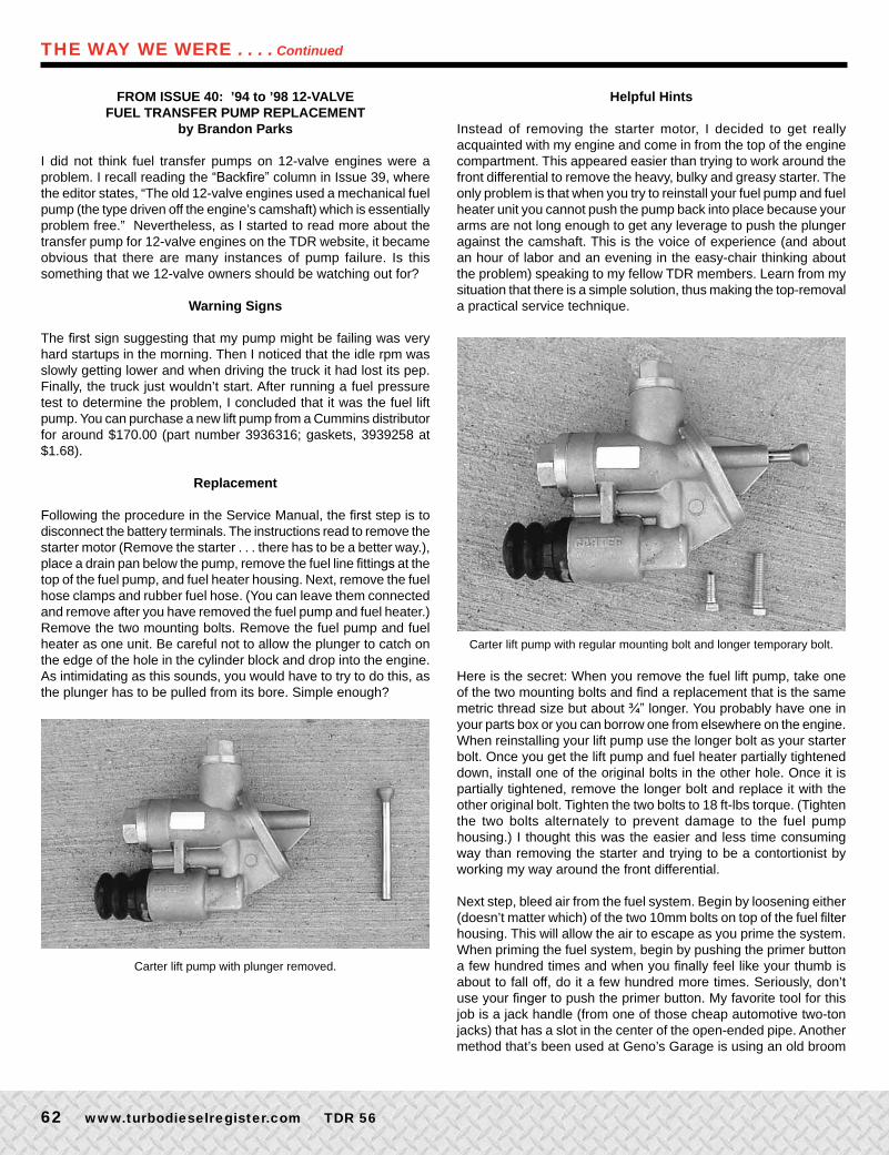
Following the procedure in the Service Manual, the first step is to disconnect the battery terminals. The instructions read to remove the starter motor (Remove the starter . . . there has to be a better way.), place a drain pan below the pump, remove the fuel line fittings at the top of the fuel pump, and fuel heater housing. Next, remove the fuel hose clamps and rubber fuel hose. (You can leave them connected and remove after you have removed the fuel pump and fuel heater.) Remove the two mounting bolts. Remove the fuel pump and fuel heater as one unit. Be careful not to allow the plunger to catch on the edge of the hole in the cylinder block and drop into the engine. As intimidating as this sounds, you would have to try to do this, as the plunger has to be pulled from its bore. Simple enough?
Carter lift pump with plunger removed.
Helpful Hints
Instead of removing the starter motor, I decided to get really acquainted with my engine and come in from the top of the engine compartment. This appeared easier than trying to work around the front differential to remove the heavy, bulky and greasy starter. The only problem is that when you try to reinstall your fuel pump and fuel heater unit you cannot push the pump back into place because your arms are not long enough to get any leverage to push the plunger against the camshaft. This is the voice of experience (and about an hour of labor and an evening in the easy-chair thinking about the problem) speaking to my fellow TDR members. Learn from my situation that there is a simple solution, thus making the top-removal a practical service technique.
Carter lift pump with regular mounting bolt and longer temporary bolt.
Here is the secret: When you remove the fuel lift pump, take one of the two mounting bolts and find a replacement that is the same metric thread size but about ¾” longer. You probably have one in your parts box or you can borrow one from elsewhere on the engine. When reinstalling your lift pump use the longer bolt as your starter bolt. Once you get the lift pump and fuel heater partially tightened down, install one of the original bolts in the other hole. Once it is partially tightened, remove the longer bolt and replace it with the other original bolt. Tighten the two bolts to 18 ft-lbs torque. (Tighten the two bolts alternately to prevent damage to the fuel pump housing.) I thought this was the easier and less time consuming way than removing the starter and trying to be a contortionist by working my way around the front differential.
Next step, bleed air from the fuel system. Begin by loosening either (doesn’t matter which) of the two 10mm bolts on top of the fuel filter housing. This will allow the air to escape as you prime the system. When priming the fuel system, begin by pushing the primer button a few hundred times and when you finally feel like your thumb is about to fall off, do it a few hundred more times. Seriously, don’t use your finger to push the primer button. My favorite tool for this job is a jack handle (from one of those cheap automotive two-ton jacks) that has a slot in the center of the open-ended pipe. Another method that’s been used at Geno’s Garage is using an old broom
THE WAY WE WERE . . . . Continued
TDR 56 www.turbodieselregister.com 6�
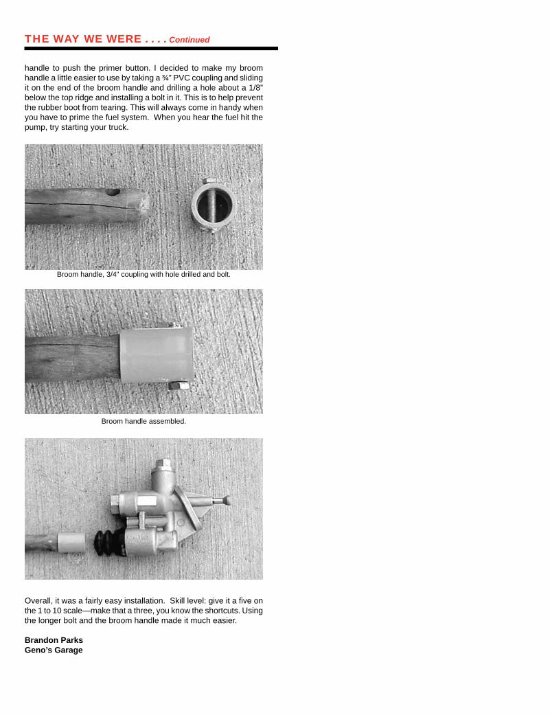
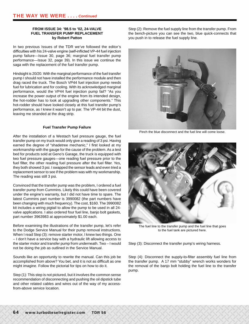
handle to push the primer button. I decided to make my broom handle a little easier to use by taking a ¾” PVC coupling and sliding it on the end of the broom handle and drilling a hole about a 1/8” below the top ridge and installing a bolt in it. This is to help prevent the rubber boot from tearing. This will always come in handy when you have to prime the fuel system. When you hear the fuel hit the pump, try starting your truck.
Broom handle, 3/4” coupling with hole drilled and bolt.
Broom handle assembled.
Overall, it was a fairly easy installation. Skill level: give it a five on the 1 to 10 scale—make that a three, you know the shortcuts. Using the longer bolt and the broom handle made it much easier.
Brandon ParksGeno’s Garage
THE WAY WE WERE . . . . Continued
• Routine axle maintenance without removing the cover
• Magnetic dipstick and drain plug • All stainless steel hardware included • Finned aircraft aluminum casting • O-rings require no sealant or gasket• Everything included for “do it yourself”
service and installation
Mag-Hytec, Inc. Van Nuys, California, tel (818)786-8325www.mag-hytec.com
Differential Covers that won’t give out on those tough hauls
KEEP YOUR END COOL
The Mag-Hytec rear Differential cover is available for the Dana models 44, 60, 70 & 80,Dodge 12-9.25,& Dodge Front 60, Ford Models 10-8.8, 12-9.75, 12-10.25, 12-10.5 &
Dana 60 front for F350 up to 98, front 99 & up coming, GM models 10-8.5, 14-9.5, 14.10.5 & 14-12.0
Also available DELUXE TRANSMISSION PANS forDodge 727-D & 727-DD, Ford 4R100/E40D and GM 4L80E & 4L60E.
Model 80 Model 70 inside viewand all parts included.
Requires only allen key wrenches forservice and installation.
maghytech ad 10/7/04 4:06 PM Page 1
6� www.turbodieselregister.com TDR 56
Step (2): Remove the fuel supply line from the transfer pump. From the bench-picture you can see the two, blue quick-connects that you push in to release the fuel supply line.
Pinch the blue disconnect and the fuel line will come loose.
The fuel line to the transfer pump and the fuel line that goes to the fuel tank are pictured here.
Step (3): Disconnect the transfer pump’s wiring harness.
Step (4): Disconnect the supply-to-filter assembly fuel line from the transfer pump. A 17 mm “stubby” wrench works wonders for the removal of the banjo bolt holding the fuel line to the transfer pump.
l
l
l
FROM ISSUE 34: ’98.5 to ’02, 24-VALVE FUEL TRANSFER PUMP REPLACEMENT
by Robert Patton
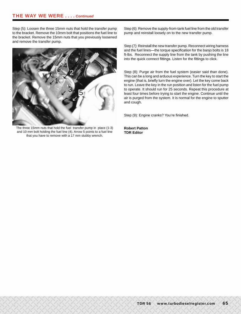
In two previous Issues of the TDR we’ve followed the editor’s difficulties with his 24-valve engine (self-inflicted VP-44 fuel injection pump failure—Issue 30, page 36; marginal fuel transfer pump performance—Issue 32, page 39). In this issue we continue the saga with the replacement of the fuel transfer pump.
Hindsight is 20/20. With the marginal performance of the fuel transfer pump I should not have installed the performance module and then drag raced the truck. The Bosch VP44 fuel injection pump needs fuel for lubrication and for cooling. With its acknowledged marginal performance, would the VP44 fuel injection pump fail? “As you increase the power output of the engine from its intended design, the hot-rodder has to look at upgrading other components.” This hot-rodder should have looked closely at this fuel transfer pump’s performance, as I knew it wasn’t up to par. The VP-44 bit the dust, leaving me stranded at the drag strip.
Fuel Transfer Pump Failure
After the installation of a Westach fuel pressure gauge, the fuel transfer pump on my truck would only give a reading of 3 psi. Having earned the degree of “shadetree mechanic,” I first looked at my workmanship with the gauge for the cause of the problem. As a test bed for products sold at Geno’s Garage, the truck is equipped with two fuel pressure gauges—one reading fuel pressure prior to the fuel filter, the other reading fuel pressure after the fuel filter. Yes, they both showed 3 psi. I swapped the sensor leads and even tried a replacement sensor to see if the problem was with my workmanship. The reading was still 3 psi.
Convinced that the transfer pump was the problem, I ordered a fuel transfer pump from Cummins. Likely this could have been covered under the engine’s warranty, but I did not have time to spare. The latest Cummins part number is 3990082 (the part numbers have been changing with much frequency). The cost, $160. The 3990082 kit includes a wiring pigtail to allow the pump to be used in all 24-valve applications. I also ordered four fuel line, banjo bolt gaskets, part number 3963983 at approximately $1.00 each.
Before examining the illustrations of the transfer pump, let’s refer to the Dodge Service Manual for their pump removal instructions. When I read Step (3): remove starter motor, I knew two things. One – I don’t have a service bay with a hydraulic lift allowing access to the starter motor and transfer pump from underneath. Two – I would not be doing the job as outlined in the Service Manual.
Sounds like an opportunity to rewrite the manual. Can this job be accomplished from above? You bet, and it is not as difficult as one might imagine. Follow the pictorial for tips on how to do it.
Step (1): This step is not pictured, but it involves the common sense recommendation of disconnecting and pushing the oil dipstick tube and other related cables and wires out of the way of my access-from-above service location.
THE WAY WE WERE . . . . Continued
TDR 56 www.turbodieselregister.com 65
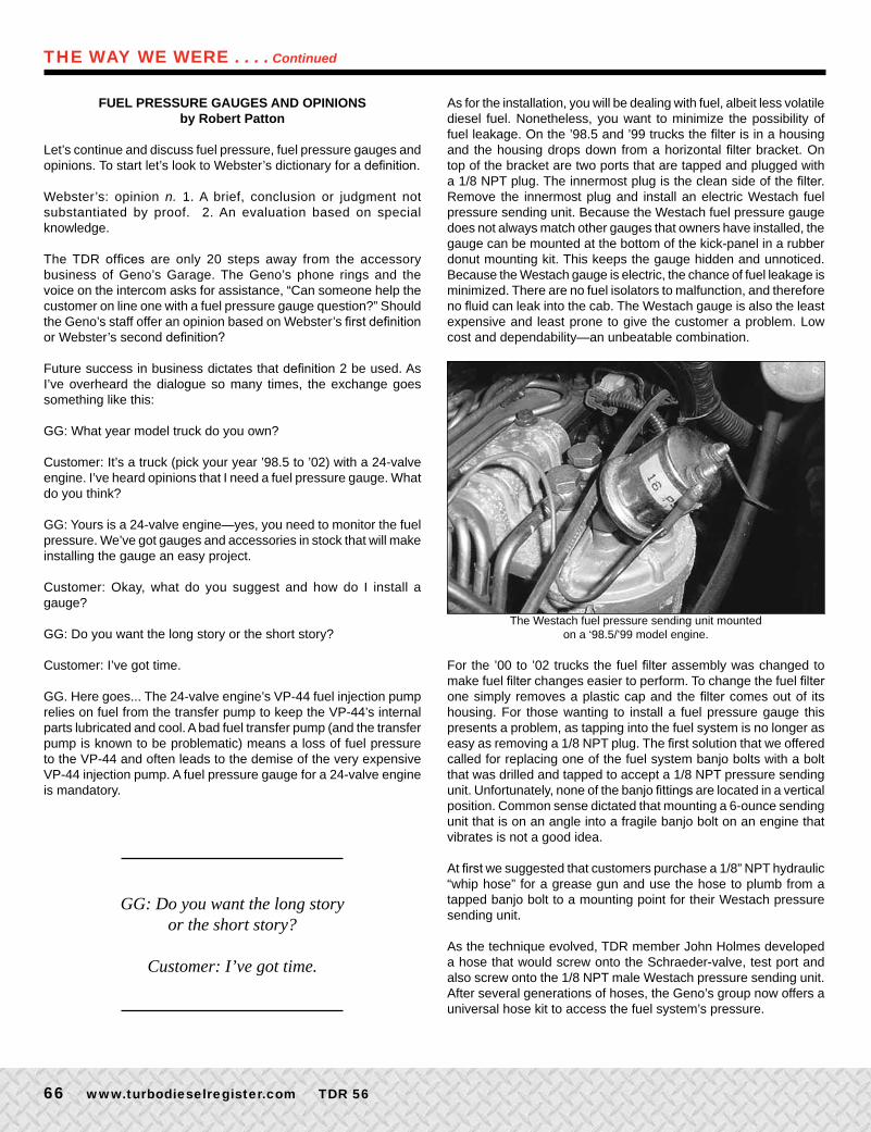
Step (5): Loosen the three 15mm nuts that hold the transfer pump to the bracket. Remove the 10mm bolt that positions the fuel line to the bracket. Remove the 15mm nuts that you previously loosened and remove the transfer pump.
The three 15mm nuts that hold the fuel transfer pump in place (1-3)and 10 mm bolt holding the fuel line (4). Arrow 5 points to a fuel line
that you have to remove with a 17 mm stubby wrench.
l
ll
ll
12
3 5
4
THE WAY WE WERE . . . . Continued
Step (6): Remove the supply-from-tank fuel line from the old transfer pump and reinstall loosely on to the new transfer pump.
Step (7): Reinstall the new transfer pump. Reconnect wiring harness and the fuel lines—the torque specification for the banjo bolts is 18 ft-lbs. Reconnect the supply line from the tank by pushing the line into the quick connect fittings. Listen for the fittings to click.
Step (8): Purge air from the fuel system (easier said than done). This can be a long and arduous experience. Turn the key to start the engine (that is, briefly turn the engine over). Let the key come back to run. Leave the key in the run position and listen for the fuel pump to operate. It should run for 25 seconds. Repeat this procedure at least four times before trying to start the engine. Continue until the air is purged from the system. It is normal for the engine to sputter and cough.
Step (9): Engine cranks? You’re finished.
Robert PattonTDR Editor
www.fostertruck.com/dodge1711 CENTER ST, TACOMA,WA 98409
New OEM Fuel solenoidNew replacement boot
Brand new OEM Denso starters
Marine grade fuels hose kits
Parts for allDenso starters
Super StarterContact kit,Completewith installinstructions
NEW, 70ampFuel shutoff relay
Contacts mag add. 11.pub page 1
Monday, June 05, 2006 10:15
66 www.turbodieselregister.com TDR 56
FUEL PRESSURE GAUGES AND OPINIONS by Robert Patton
Let’s continue and discuss fuel pressure, fuel pressure gauges and opinions. To start let’s look to Webster’s dictionary for a definition.
Webster’s: opinion n. 1. A brief, conclusion or judgment not substantiated by proof. 2. An evaluation based on special knowledge.
The TDR offices are only 20 steps away from the accessory business of Geno’s Garage. The Geno’s phone rings and the voice on the intercom asks for assistance, “Can someone help the customer on line one with a fuel pressure gauge question?” Should the Geno’s staff offer an opinion based on Webster’s first definition or Webster’s second definition?
Future success in business dictates that definition 2 be used. As I’ve overheard the dialogue so many times, the exchange goes something like this:
GG: What year model truck do you own?
Customer: It’s a truck (pick your year ’98.5 to ’02) with a 24-valve engine. I’ve heard opinions that I need a fuel pressure gauge. What do you think?
GG: Yours is a 24-valve engine—yes, you need to monitor the fuel pressure. We’ve got gauges and accessories in stock that will make installing the gauge an easy project.
Customer: Okay, what do you suggest and how do I install a gauge?
GG: Do you want the long story or the short story?
Customer: I’ve got time.
GG. Here goes... The 24-valve engine’s VP-44 fuel injection pump relies on fuel from the transfer pump to keep the VP-44’s internal parts lubricated and cool. A bad fuel transfer pump (and the transfer pump is known to be problematic) means a loss of fuel pressure to the VP-44 and often leads to the demise of the very expensive VP-44 injection pump. A fuel pressure gauge for a 24-valve engine is mandatory.
As for the installation, you will be dealing with fuel, albeit less volatile diesel fuel. Nonetheless, you want to minimize the possibility of fuel leakage. On the ’98.5 and ’99 trucks the filter is in a housing and the housing drops down from a horizontal filter bracket. On top of the bracket are two ports that are tapped and plugged with a 1/8 NPT plug. The innermost plug is the clean side of the filter. Remove the innermost plug and install an electric Westach fuel pressure sending unit. Because the Westach fuel pressure gauge does not always match other gauges that owners have installed, the gauge can be mounted at the bottom of the kick-panel in a rubber donut mounting kit. This keeps the gauge hidden and unnoticed. Because the Westach gauge is electric, the chance of fuel leakage is minimized. There are no fuel isolators to malfunction, and therefore no fluid can leak into the cab. The Westach gauge is also the least expensive and least prone to give the customer a problem. Low cost and dependability—an unbeatable combination.
The Westach fuel pressure sending unit mounted on a ‘98.5/’99 model engine.
For the ’00 to ’02 trucks the fuel filter assembly was changed to make fuel filter changes easier to perform. To change the fuel filter one simply removes a plastic cap and the filter comes out of its housing. For those wanting to install a fuel pressure gauge this presents a problem, as tapping into the fuel system is no longer as easy as removing a 1/8 NPT plug. The first solution that we offered called for replacing one of the fuel system banjo bolts with a bolt that was drilled and tapped to accept a 1/8 NPT pressure sending unit. Unfortunately, none of the banjo fittings are located in a vertical position. Common sense dictated that mounting a 6-ounce sending unit that is on an angle into a fragile banjo bolt on an engine that vibrates is not a good idea.
At first we suggested that customers purchase a 1/8” NPT hydraulic “whip hose” for a grease gun and use the hose to plumb from a tapped banjo bolt to a mounting point for their Westach pressure sending unit.
As the technique evolved, TDR member John Holmes developed a hose that would screw onto the Schraeder-valve, test port and also screw onto the 1/8 NPT male Westach pressure sending unit. After several generations of hoses, the Geno’s group now offers a universal hose kit to access the fuel system’s pressure.
THE WAY WE WERE . . . . Continued
GG: Do you want the long story
or the short story?
Customer: I’ve got time.
Superchips_Turbo_Diesel_Registry1 1 3/8/2007 9:17:59 AM
6� www.turbodieselregister.com TDR 56
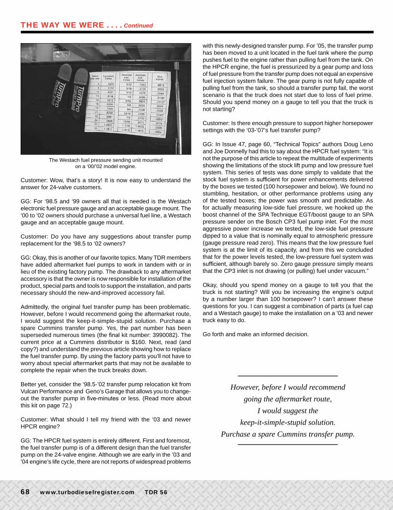
The Westach fuel pressure sending unit mounted on a ‘00/’02 model engine.
Customer: Wow, that’s a story! It is now easy to understand the answer for 24-valve customers.
GG: For ‘98.5 and ‘99 owners all that is needed is the Westach electronic fuel pressure gauge and an acceptable gauge mount. The ‘00 to ‘02 owners should purchase a universal fuel line, a Westach gauge and an acceptable gauge mount.
Customer: Do you have any suggestions about transfer pump replacement for the ‘98.5 to ‘02 owners?
GG: Okay, this is another of our favorite topics. Many TDR members have added aftermarket fuel pumps to work in tandem with or in lieu of the existing factory pump. The drawback to any aftermarket accessory is that the owner is now responsible for installation of the product, special parts and tools to support the installation, and parts necessary should the new-and-improved accessory fail.
Admittedly, the original fuel transfer pump has been problematic. However, before I would recommend going the aftermarket route, I would suggest the keep-it-simple-stupid solution. Purchase a spare Cummins transfer pump. Yes, the part number has been superseded numerous times (the final kit number: 3990082). The current price at a Cummins distributor is $160. Next, read (and copy?) and understand the previous article showing how to replace the fuel transfer pump. By using the factory parts you’ll not have to worry about special aftermarket parts that may not be available to complete the repair when the truck breaks down.
Better yet, consider the ‘98.5-’02 transfer pump relocation kit from Vulcan Performance and Geno’s Garage that allows you to change-out the transfer pump in five-minutes or less. (Read more about this kit on page 72.)
Customer: What should I tell my friend with the ‘03 and newer HPCR engine?
GG: The HPCR fuel system is entirely different. First and foremost, the fuel transfer pump is of a different design than the fuel transfer pump on the 24-valve engine. Although we are early in the ’03 and ’04 engine’s life cycle, there are not reports of widespread problems
with this newly-designed transfer pump. For ’05, the transfer pump has been moved to a unit located in the fuel tank where the pump pushes fuel to the engine rather than pulling fuel from the tank. On the HPCR engine, the fuel is pressurized by a gear pump and loss of fuel pressure from the transfer pump does not equal an expensive fuel injection system failure. The gear pump is not fully capable of pulling fuel from the tank, so should a transfer pump fail, the worst scenario is that the truck does not start due to loss of fuel prime. Should you spend money on a gauge to tell you that the truck is not starting?
Customer: Is there enough pressure to support higher horsepower settings with the ‘03-’07’s fuel transfer pump?
GG: In Issue 47, page 60, “Technical Topics” authors Doug Leno and Joe Donnelly had this to say about the HPCR fuel system: “It is not the purpose of this article to repeat the multitude of experiments showing the limitations of the stock lift pump and low pressure fuel system. This series of tests was done simply to validate that the stock fuel system is sufficient for power enhancements delivered by the boxes we tested (100 horsepower and below). We found no stumbling, hesitation, or other performance problems using any of the tested boxes; the power was smooth and predictable. As for actually measuring low-side fuel pressure, we hooked up the boost channel of the SPA Technique EGT/boost gauge to an SPA pressure sender on the Bosch CP3 fuel pump inlet. For the most aggressive power increase we tested, the low-side fuel pressure dipped to a value that is nominally equal to atmospheric pressure (gauge pressure read zero). This means that the low pressure fuel system is at the limit of its capacity, and from this we concluded that for the power levels tested, the low-pressure fuel system was sufficient, although barely so. Zero gauge pressure simply means that the CP3 inlet is not drawing (or pulling) fuel under vacuum.”
Okay, should you spend money on a gauge to tell you that the truck is not starting? Will you be increasing the engine’s output by a number larger than 100 horsepower? I can’t answer these questions for you. I can suggest a combination of parts (a fuel cap and a Westach gauge) to make the installation on a ’03 and newer truck easy to do.
Go forth and make an informed decision.
THE WAY WE WERE . . . . Continued
However, before I would recommend
going the aftermarket route,
I would suggest the
keep-it-simple-stupid solution.
Purchase a spare Cummins transfer pump.
714.378.1660 | CLIENT: SNOW PERFORMANCE | DIESEL | TDR | SPRING 07
Juice up your diesel with an injection...
...a water-methanol injection, that is. The use of water-methanol injection has
been proven to add power to everything from the P51 Mustang to Diesel Land
Speed Record Holders. The Snow Performance high pressure/high volume
injection system allows for maximized torque and increased reliability by cooling
exhaust gas temps. Take a look and see for yourself why some of the fastest
performance diesels and championship race teams have been juiced-up by
Snow Performance - the water-methanol injection experts.
+70
Stage III Diesel KitNEW LCD Now Available. +70 HP!
See web for dyno and other diesel applications.
COMPLETEATOMIZATION
www.snowperformance.net • Toll Free: (866)365-2762
SP_DIESEL_TDR.qxd 2/26/07 3:14 PM Page 1