application note:dtmf signal detection using z8 encore! xp
TRANSCRIPT

AN033501-1011
Abstract
This application note demonstrates Dual-Tone Multi-Frequency (DTMF) signal detection using Zilog’s Z8F64xx Series microcontrollers. The firmware for these Z8F64xx Series microcontrollers is based on the Goertzel Algorithm; three (3) testing formats are used to ensure that this firmware is working in compliance with the International Telecommunica-tion Union (ITU) Q.24 Recommendation. This ITU Recommendation states that the mini-mum valid DTMF tone duration is 40 ms and that the minimum pause duration is also 40 ms.
The source code file associated with this application note, AN0335-SC01.zip, is available for download on zilog.com. This source code has been tested with version 5.0.0 of ZDS II for Z8 Encore! XP-powered MCUs. Subsequent releases of ZDS II may require you to modify the code supplied with this application note.Additional source code for this application is contained in the Z8 Encore! Applications Code Library, available for download from the Application Sample Libraries page on the Zilog website.
This application note has not been tested for incoming calls to a standard telephone.
Features
The main features described in this application note are:
• Valid tone detection within the 40 ms specification
• The 8-bit Z8F64xx Series MCU used as a digital signal processor
• Firmware based on the Goertzel Algorithm
Discussion
DTMF signaling is commonly used in telephone equipment. A DTMF signal is a combi-nation of two (2) pure sinusoidal waves, each with differing frequencies. Based on the ITU Recommendation, there are eight (8) frequencies involved in DTMF signaling. These fre-quencies are grouped as Low Frequency and High Frequency, as shown in Table 1.
Note:
Caution:
AN033501-1011
Application Note
DTMF Signal Detection Using Z8 Encore! XP F64xx Series MCUs
Page 1 of 21
DTMF Signal Detection Using Z8 Encore! XP F64xx Series MCUsApplication Note
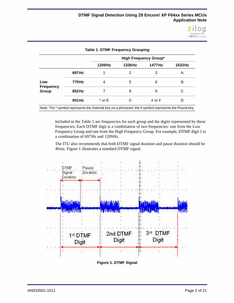
Included in the Table 1 are frequencies for each group and the digits represented by these frequencies. Each DTMF digit is a combination of two frequencies: one from the Low Frequency Group and one from the High Frequency Group. For example, DTMF digit 1 is a combination of 697 Hz and 1209 Hz.
The ITU also recommends that both DTMF signal duration and pause duration should be 40 ms. Figure 1 illustrates a standard DTMF signal.
Table 1. DTMF Frequency Grouping
High Frequency Group*
1209 Hz 1336 Hz 1477 Hz 1633 Hz
Low Frequency Group
697 Hz 1 2 3 A
770 Hz 4 5 6 B
852 Hz 7 8 9 C
941 Hz * or E 0 # or F D
Note: The * symbol represents the Asterisk key on a phoneset; the # symbol represents the Pound key.
Figure 1. DTMF Signal
AN033501-1011 Page 2 of 21

DTMF Signal Detection Using Z8 Encore! XP F64xx Series MCUsApplication Note
Theory of OperationThe Goertzel Algorithm is used in the implementation of DTMF detection. It is a Discrete Fourier Transform (DFT) method that can detect tones using less CPU power than the Fast Fourier Transform (FFT) method, and therefore is a faster method for detecting frequen-cies such as DTMF tones.
The Goertzel Algorithm is based on the DFT equation shown in Equation 1.
Finding its sequence from a linear filter process leads to Equation 2.
In Equation 2, the sample value n = N. Transforming Equation 2 into a linear difference equation yields Equation 3.
In Equation 3, y(–1) = 0. Getting the z-domain transfer function of the Goertzel filter yields Equation 4.
Equation 1
Equation 2
Equation 3
Equation 4
AN033501-1011 Page 3 of 21

DTMF Signal Detection Using Z8 Encore! XP F64xx Series MCUsApplication Note
Transforming Equation 4 into a difference equation leads to Equation 5.
Because there are only two frequencies present in a DTMF tone, we are no longer inter-ested in acquiring the real and imaginary frequency components of a given signal. The focus of computations is now applied to the power parameters of the signal, which can be computed using the formula shown in Equation 6.
Hardware Architecture
The high-pass filter, in Figure 2, is used to demonstrate detection of DTMF signals from telephone unit. Input to the high-pass filter is from the tip and ring of the telephone line; its output is connected to the ANA0 analog input of the Z8F64xx Series microcontroller.
Equation 5
Equation 6
Figure 2. High-Pass Filter
AN033501-1011 Page 4 of 21

DTMF Signal Detection Using Z8 Encore! XP F64xx Series MCUsApplication Note
The high-pass filter has a cut-off frequency of approximately 200 Hz; its primary function is to filter out the DC component from the telephone line and to suppress low-frequency line interference. The cut-off frequency is determined using the formula:
In the above equation, the variables are defined as:
R = R1 + (R2 || R3)
C = C1
In telephony, the tip is the ground (positive) and the ring is the battery (negative). The voltage level upon ring, with respect to tip, is –6 Volts DC upon off-hook; the DTMF sig-nal from the telephone line is superimposed on this negative DC voltage. Passing to the high-pass filter, this –6 V DC is filtered out. Because this –6 V is removed on the output going to ANA0, the DTMF signal subsequently rides on a 1.65 V DC bias voltage; this DC bias voltage is computed using the voltage divider formula:
In addition, capacitor C2 is used to filter out interference to and from the 3.3 V reference voltage.
Z8F64xx Development Board SetupThe ADC block of the Z8F64xx Series MCU is configured to operate using an external VREF. Figure 3 shows how to set this up on the Z8F64xx Development Board by connect-ing Pin 1 of J2 and Pin 59 of JP2. These pins represent the external ADC VREF of the MCU and one of the VDD pins available on the development board, respectively. The ter-minal of ANA0, which is Pin 21 of J2, is shown to indicate the connection point of the fil-ters described above.
fc =1
2πRC
AN033501-1011 Page 5 of 21

DTMF Signal Detection Using Z8 Encore! XP F64xx Series MCUsApplication Note
Software Implementation
This section presents the firmware developed for this application note. Topics are divided into: DTMF Detection and Display; ADC and Timer; and the Main routine.
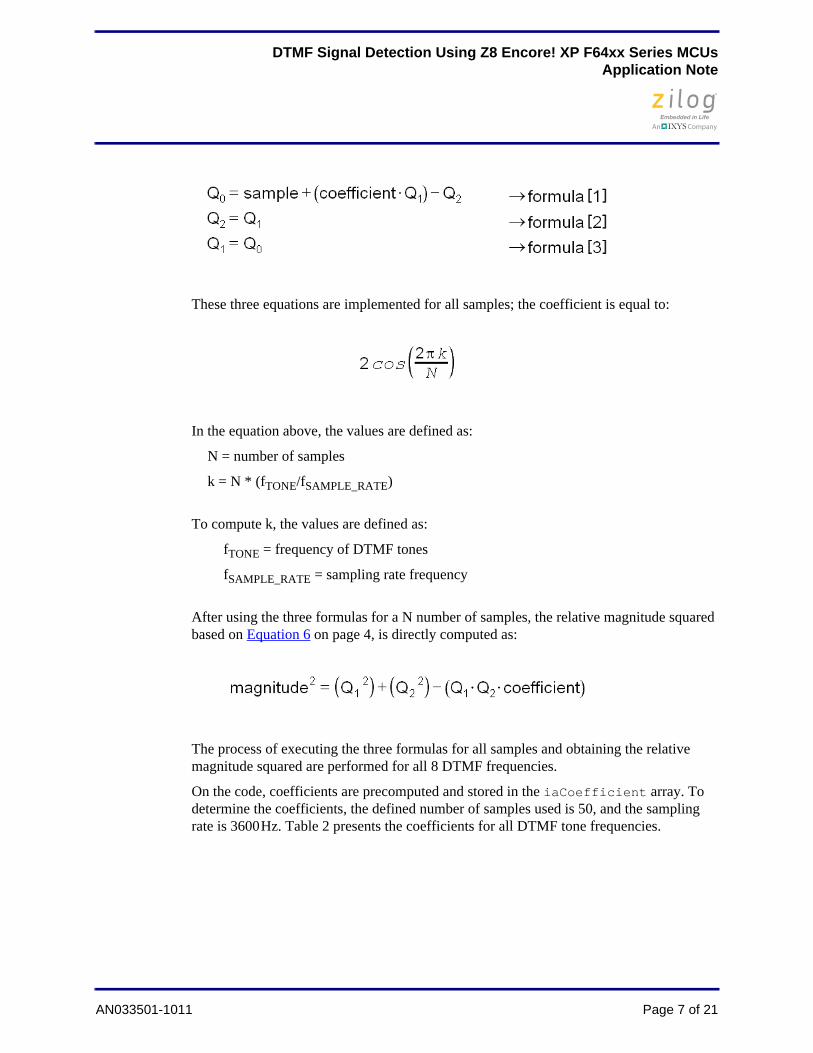
DTMF Detection and Digit DisplayThe DTMF detection application focuses on void Goertzel_Algorithm (void). With this function, there are 3 formulas used for processing samples from the ADC. These equations, which follow, are derived from Equation 5 on page 4.
Figure 3. ADC External VREF Connection and ANA0 Terminal
AN033501-1011 Page 6 of 21
DTMF Signal Detection Using Z8 Encore! XP F64xx Series MCUsApplication Note
These three equations are implemented for all samples; the coefficient is equal to:
In the equation above, the values are defined as:
N = number of samples
k = N * (fTONE/fSAMPLE_RATE)
To compute k, the values are defined as:
fTONE = frequency of DTMF tones
fSAMPLE_RATE = sampling rate frequency
After using the three formulas for a N number of samples, the relative magnitude squared based on Equation 6 on page 4, is directly computed as:
The process of executing the three formulas for all samples and obtaining the relative magnitude squared are performed for all 8 DTMF frequencies.
On the code, coefficients are precomputed and stored in the iaCoefficient array. To determine the coefficients, the defined number of samples used is 50, and the sampling rate is 3600 Hz. Table 2 presents the coefficients for all DTMF tone frequencies.
AN033501-1011 Page 7 of 21

DTMF Signal Detection Using Z8 Encore! XP F64xx Series MCUsApplication Note
To make MCU processing faster, coefficients are converted into integers by multiplying them by 16. Table 3 lists these integer coefficients as used on the code.
Magnitudes for 8 DTMF tone frequencies are stored in the iaEnergy_Magnitude array. Elements 0 to 3 of this array hold the magnitudes for the tested low-frequency group; ele-ments 4 to 7 correspond to the high-frequency group. This array is used by void DTMF_DigitCodeID (void) to identify the highest magnitude on the low-frequency group and the highest magnitude on the high-frequency group. This function is performed by comparing all of the magnitudes on each group. The resulting array index of the highest magnitude for the low-frequency group and the high-frequency group is saved in ucLowFreq_HighestMagIdx and ucHighFreq_HighestMagIdx, respectively. These indices are combined in ucDTMF_DigitCode to form the DTMF Digit Code shown in Table 4. ucDTMF_DigitCode is used by void DTMF_DigitDisplay (void) to iden-tify the code and display the appropriate DTMF Digit on the host PC’s HyperTerminal window.
The void Goertzel_Algorithm (void) statement obtains N number of samples before the mathematical operations are computed; the storing of samples to the ucSample array occurs in intervals of 1/3600 sec. These samples from the ADC are scaled down with a factor defined by the SCALE_DOWN constant. Aside from these ADC samples, terms with coefficients are also scaled down by a factor of SCALE_DOWN_COEFF. Because the vari-ables used are 16-bit integers, the scaling down of the ADC samples and the mathematical terms with coefficients must be performed to avoid overflow.
ADC and Timer
Upon void ADC_Init(void), the ADC is configured to generate an interrupt after con-version is completed. It is set to run in Continuous Mode, with an external VREF and with
Table 2. Coefficients
Sampling Rate 3600 3600 3600 3600 3600 3600 3600 3600
N (# of samples) 50 50 50 50 50 50 50 50
DTMF Tone Freq 697 770 852 941 1209 1336 1477 1633
k 0.19361 0.21389 0.23667 0.26139 0.33583 0.37111 0.41028 0.453611
coefficient 0.69503 0.45123 0.16886 –0.14133 –1.0252 –1.3775 –1.68913 –1.91481
Table 3. Integer Coefficients
coefficient 11 7 3 –2 –16 –22 –27 –31
Table 4. DTMF Digit Codes
DTMF Digit 0 1 2 3 4 5 6 7 8 9 A B C D* or E
# or F
DTMF Digit Code (hex) 28 11 21 41 12 22 42 14 24 44 81 82 84 88 18 48
AN033501-1011 Page 8 of 21

DTMF Signal Detection Using Z8 Encore! XP F64xx Series MCUsApplication Note
ANA0 as the analog input for the DTMF signal. Upon every ADC interrupt, void interrupt isrADC (void) is executed to obtain a sample from the ADC Data regis-ters, extract the 10 bit ADC data, and store this data to uiADC_SampleData.
Timer0 is set to generate an interrupt every 1/3600 sec. Upon every Timer0 interrupt, void interrupt isrTimer0 (void) is executed to set the ucTimeToGetSample. In turn, void Goertzel_Algorithm (void) is informed that 1/3600 sec has expired, and the ADC sample data can be stored to ucSample array.
Main
The main routine calls the functions to initialize the ADC, Timer0 and UART. After all initializations are performed, the main routine constantly checks for the presence of valid DTMF signal amplitudes through void Debounce_DigitStart (void). If a valid DTMF signal amplitude is present, void Goertzel_Algorithm (void) is executed. After the detected signal is processed and identified, a DTMF digit is displayed on the host PC’s HyperTerminal screen. Upon this display, void main (void) continues to execute void Debounce_DigitEnd (void) to check the analog input until the magnitude of the currently-detected DTMF signal is relatively low.
void Debounce_DigitStart (void) is used to check whether a valid DTMF magni-tude is present. If the ADC sample data is below the threshold defined by THRES_AMPLITUDE, it means there is no DTMF signal on the line. For the testing setups (refer to the Testing/Demonstrating the Application section on page 10), these thresholds are listed Table 5.
THRES_AMPLITUDE depends on the ADC value when the line is idle or when the line has no DTMF signal. For example, the value of THRES_AMPLITUDE, as used in Setup 1, is 100 because the ADC value, on idle, is 56. If this idle voltage is different from the idle voltage value listed in Table 5, use the formula below to compute its ADC value as the basis for THRES_AMPLITUDE.
void Debounce_DigitEnd (void) is used to check the line until it becomes idle again. Part of this function is void Goertzel_Algorithm (void), in which all mag-
Table 5. Threshold Amplitude
Setup Number THRES_AMPLITUDE ANA0 VIN at Idle ADC Value
1 100 180 mV 56
2 600 1.46 V 452
3 900 1.78 V 551
AN033501-1011 Page 9 of 21

DTMF Signal Detection Using Z8 Encore! XP F64xx Series MCUsApplication Note
nitudes are added. If the total magnitude is above THRES_ENERGY_MAG, the currently-detected DTMF signal is still present on the analog input. Otherwise, the line is idle again and the code is ready for the next detection process.
Please refer to Appendix A. Flowcharts on page 18 to review the DTMF Decoder algorithms.
Testing/Demonstrating the Application
To demonstrate this DTMF detection application, three different setups are used. These three setups are:
Setup 1. The AN0248-SC01 source code as the DTMF generator.
Setup 2. Two telephone units powered together and used as a DTMF generator.
Setup 3. A live telephone line and a telephone unit as a DTMF generator.
Setup 1 demonstrates tone detection under a noise-free environment. In this setup, the DTMF generator described in AN0248 is used. DTMF tone generated by DevBoard1, as shown in Figure 4, should be correctly identified by DevBoard2 and displayed on Com-puter 2.
Setup 2 and Setup 3 demonstrate tone detection within a noisy environment, which is pres-ent in the actual telephone line. For these setups, pressed key on the telephone unit will be detected by the development board and this will be displayed on PC's HyperTerminal.
Equipment UsedHere is the list of equipment used in the development and testing of this application note:
• Two (2) Z8 Encore! XP Z8F64xx Series Development Kits
• 18 V power supply
• Telephone units
• Oscilloscope
• Personal computer
Setup 1Two personal computers (Computer 1 and Computer 2) and two Z8F64xx Series develop-ment kits are used in this setup. The interface between each kit’s development board and its host PC is an RS-232 cable (see Figure 4). The PC1 and PC7 terminals of DevBoard1 are connected to the input of the low-pass filter. The output of this low-pass filter is con-nected to the ANA0 analog input of DevBoard2. Refer to Figure 3 on page 6 for the DevBoard2 setup.
Please refer to the Zilog Application Note titled Generating DTMF Tones Using Z8 Encore! MCUs (AN0248) for details about the low-pass filter design.
Note:
AN033501-1011 Page 10 of 21
DTMF Signal Detection Using Z8 Encore! XP F64xx Series MCUsApplication Note
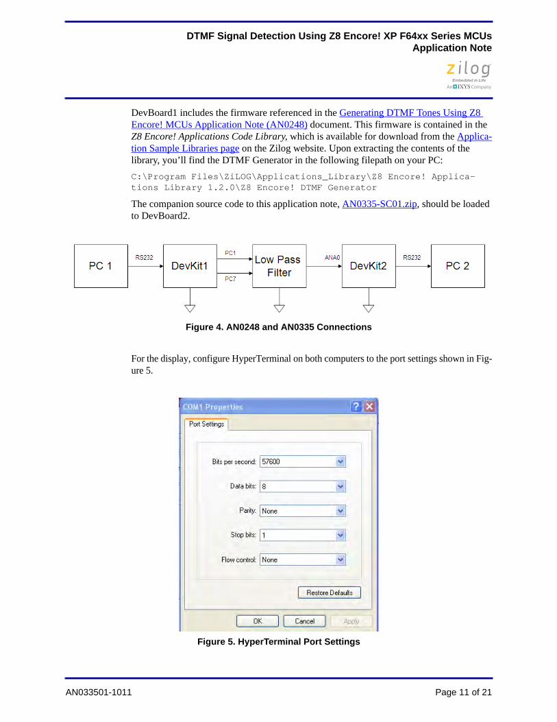
DevBoard1 includes the firmware referenced in the Generating DTMF Tones Using Z8 Encore! MCUs Application Note (AN0248) document. This firmware is contained in the Z8 Encore! Applications Code Library, which is available for download from the Applica-tion Sample Libraries page on the Zilog website. Upon extracting the contents of the library, you’ll find the DTMF Generator in the following filepath on your PC:
C:\Program Files\ZiLOG\Applications_Library\Z8 Encore! Applica-tions Library 1.2.0\Z8 Encore! DTMF Generator
The companion source code to this application note, AN0335-SC01.zip, should be loaded to DevBoard2.
For the display, configure HyperTerminal on both computers to the port settings shown in Fig-ure 5.
Figure 4. AN0248 and AN0335 Connections
Figure 5. HyperTerminal Port Settings
AN033501-1011 Page 11 of 21
DTMF Signal Detection Using Z8 Encore! XP F64xx Series MCUsApplication Note
In this setup, there are two types of demonstration modes that can be tested: Sequential Mode and Random Mode.
Sequential Mode Procedure
Observe the following procedure to demonstrate Sequential Mode.
1. Download the DTMF Generator code to DevBoard1 (see the beginning of this Setup 1 section to obtain this code).
2. Open the AN0335-SC01 source code in ZDS II v5.0 for Z8 Encore!.
3. In the main.c file, comment out the #define THRES_AMPLITUDE statement, as fol-lows:
//#define THRES_AMPLITUDE 900 // DTMF tone amplitude threshold // value (live telephone line)
//#define THRES_AMPLITUDE 600 // DTMF tone amplitude threshold // value (telephone to telephone // setup)
#define THRES_AMPLITUDE 100 // DTMF tone amplitude threshold // value (AN0248 setup)
4. Compile and download the code to DevBoard2.
5. Configure HyperTerminal on both computers with the settings shown in Figure 5.
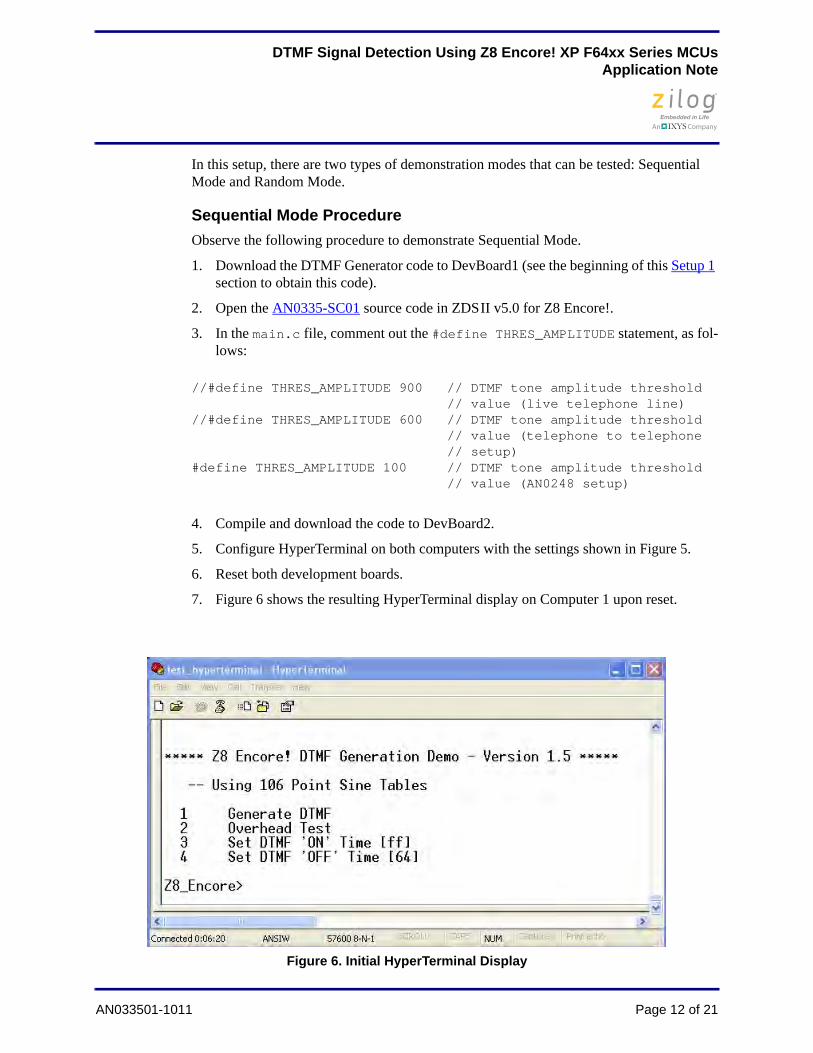
6. Reset both development boards.
7. Figure 6 shows the resulting HyperTerminal display on Computer 1 upon reset.
Figure 6. Initial HyperTerminal Display
AN033501-1011 Page 12 of 21
DTMF Signal Detection Using Z8 Encore! XP F64xx Series MCUsApplication Note
8. On Computer 1, set the DTMF ON time by entering a 3, then enter the DTMF ON time in milliseconds; the required format for this entry is the hexadecimal format. Fig-ure 7 provides an example for setting the DTMF ON time to 40 ms.
9. On Computer 1, set the DTMF OFF time by entering a 4, then entering the DTMF OFF time in milliseconds. Once again, the required format for this entry is the hexa-decimal format. Figure 8 shows how to set the DTMF OFF time to 40 ms.
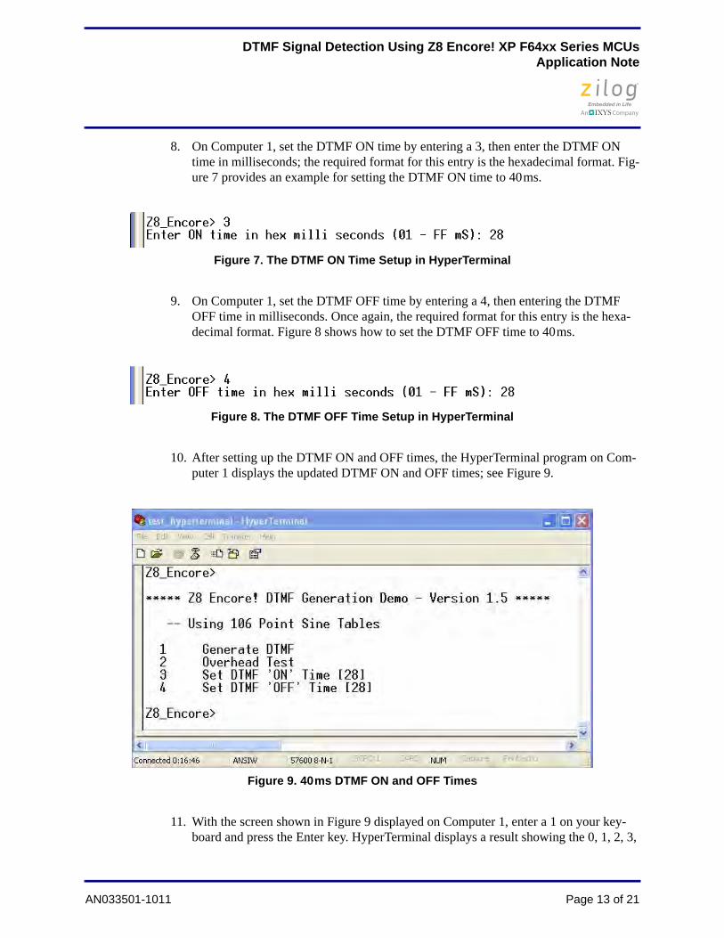
10. After setting up the DTMF ON and OFF times, the HyperTerminal program on Com-puter 1 displays the updated DTMF ON and OFF times; see Figure 9.
11. With the screen shown in Figure 9 displayed on Computer 1, enter a 1 on your key-board and press the Enter key. HyperTerminal displays a result showing the 0, 1, 2, 3,
Figure 7. The DTMF ON Time Setup in HyperTerminal
Figure 8. The DTMF OFF Time Setup in HyperTerminal
Figure 9. 40 ms DTMF ON and OFF Times
AN033501-1011 Page 13 of 21
DTMF Signal Detection Using Z8 Encore! XP F64xx Series MCUsApplication Note
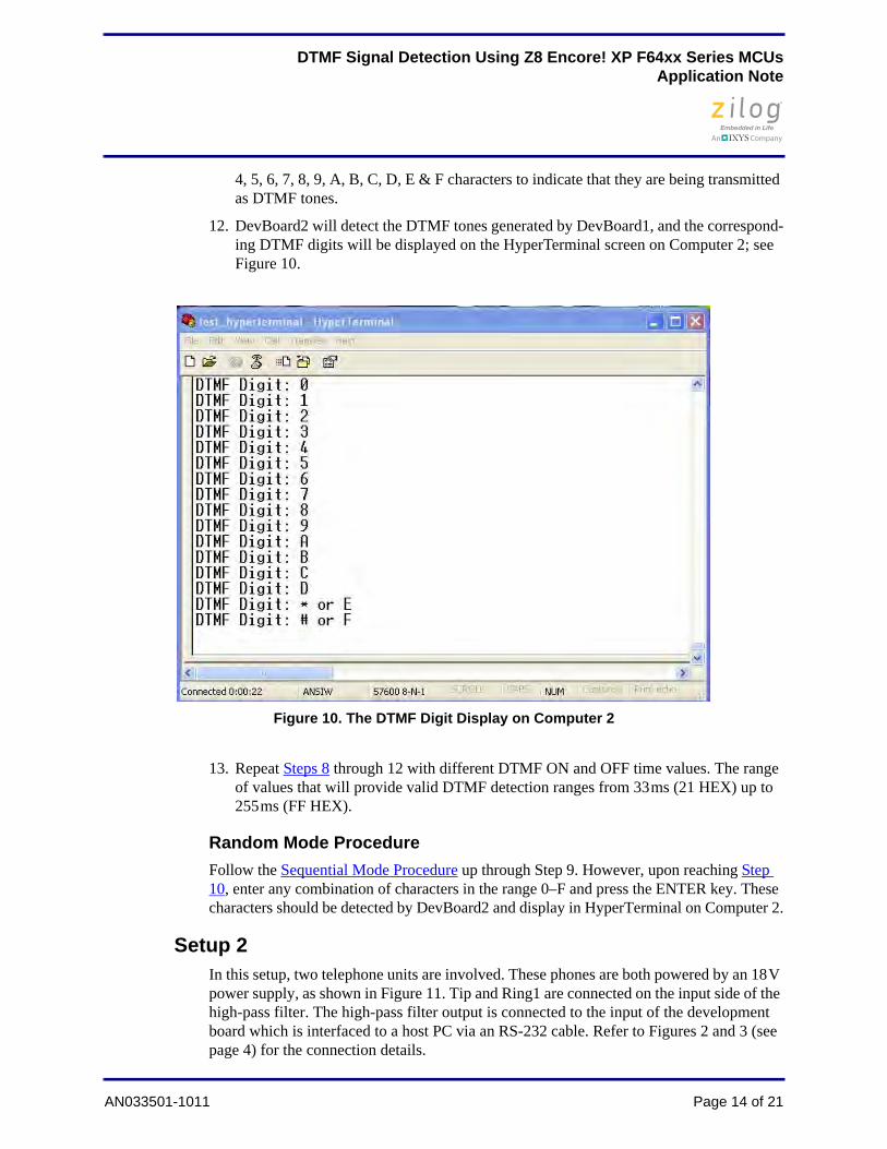
4, 5, 6, 7, 8, 9, A, B, C, D, E & F characters to indicate that they are being transmitted as DTMF tones.
12. DevBoard2 will detect the DTMF tones generated by DevBoard1, and the correspond-ing DTMF digits will be displayed on the HyperTerminal screen on Computer 2; see Figure 10.
13. Repeat Steps 8 through 12 with different DTMF ON and OFF time values. The range of values that will provide valid DTMF detection ranges from 33 ms (21 HEX) up to 255 ms (FF HEX).
Random Mode Procedure
Follow the Sequential Mode Procedure up through Step 9. However, upon reaching Step 10, enter any combination of characters in the range 0–F and press the ENTER key. These characters should be detected by DevBoard2 and display in HyperTerminal on Computer 2.
Setup 2In this setup, two telephone units are involved. These phones are both powered by an 18 V power supply, as shown in Figure 11. Tip and Ring1 are connected on the input side of the high-pass filter. The high-pass filter output is connected to the input of the development board which is interfaced to a host PC via an RS-232 cable. Refer to Figures 2 and 3 (see page 4) for the connection details.
Figure 10. The DTMF Digit Display on Computer 2
AN033501-1011 Page 14 of 21

DTMF Signal Detection Using Z8 Encore! XP F64xx Series MCUsApplication Note
Procedure
Observe the following procedure to demonstrate Setup 2.
1. Open the AN0335-SC01 source code in ZDS II v5.0 for Z8 Encore!.
2. In the main.c file, comment out the #define THRES_AMPLITUDE statement speci-fied for telephone-to-telephone setup, as follows:
//#define THRES_AMPLITUDE 900 // DTMF tone amplitude // threshold value (live telephone // line)
#define THRES_AMPLITUDE 600 // DTMF tone amplitude threshold // value (telephone to telephone // setup)
//#define THRES_AMPLITUDE 100 // DTMF tone amplitude threshold // value (AN0248 setup)
3. Compile and download the code to the development board.
4. Perform all connections as illustrated in Figure 11.
Figure 11. Two Telephone Units Functioning as a DTMF Detector
Note: 18V Power Supply is not connected to the common ground.
AN033501-1011 Page 15 of 21

DTMF Signal Detection Using Z8 Encore! XP F64xx Series MCUsApplication Note
5. Configure HyperTerminal on the PC with the port settings shown in Figure 5 on page 11.
6. Ensure that both telephone units are off-hook.
7. Reset the development board.
8. Press any key on either of the two telephone units; the corresponding DTMF digit will be displayed in the HyperTerminal window.
Setup 3In this setup, a live telephone unit is involved. Input side of the high-pass filter is con-nected to the tip and ring of the telephone line as shown in Figure 12. Output of the high-pass filter is connected to the ANA0 analog input of the development board which is inter-faced to PC via RS232 cable. Refer to Figures 2 and 3 for the appropriate connections.
Procedure
Observe the following procedure to demonstrate Setup 3.
1. Open the AN0335-SC01 source code in ZDS II v5.0 for Z8 Encore!.
2. In the main.c file, comment out the #define THRES_AMPLITUDE line that specifies the live telephone line, as follows:
#define THRES_AMPLITUDE 900 // DTMF tone amplitude // threshold value (live telephone // line)
//#define THRES_AMPLITUDE 600 // DTMF tone amplitude threshold // value (telephone to telephone // setup)
//#define THRES_AMPLITUDE 100 // DTMF tone amplitude threshold
Figure 12. A Live Telephone as a DTMF Detector
AN033501-1011 Page 16 of 21

DTMF Signal Detection Using Z8 Encore! XP F64xx Series MCUsApplication Note
// value (AN0248 setup)
3. Compile and download the code to the development board.
4. Perform all connections as illustrated in Figure 12.
5. Configure HyperTerminal on the PC with the settings shown in Figure 5 on page 11.
6. Ensure that the telephone unit is off-hook.
7. Reset the development board.
8. Press any key on the telephone unit; the corresponding DTMF digit will be displayed in the HyperTerminal window.
Results
The results from the three testing setups indicate that the code developed for this applica-tion note can detect a minimum 40 ms duration of the DTMF tone and a 40 ms pause dura-tion. It can even detect a DTMF tone duration of 33 ms and a pause duration of 33 ms.
Summary
This application note implements the Goertzel algorithm for DTMF tone detection using Zilog’s Z8F64xx Series Microcontrollers. The application passes three testing methods to generate and detect DTMF tones. The firmware described herein can be used in applica-tions that involve DTMF detection, such as caller ID and remote switching for home auto-mation using a phone line.
References
The following documents describe functional specifications and/or otherwise support this application note. With the exception of the first two documents, each is available for download from the Zilog website.
• Digital Signal Processing (4th edition) by John G. Proakis and Dimitris K. Manolakis
• EE times Design Article: The Goertzel Algorithm by Kevin Banks(http://www.eetimes.com/design/embedded/4024443/The-Goertzel-Algorithm)
• Generating DTMF Tones Using Z8 Encore! MCU Application Note (AN0248)
• Z8 Encore! XP Z8F64xx Series Product Specification (PS0199)
• Z8 Encore! XP Z8F64xx Series Development Kit User Manual (UM0151)
AN033501-1011 Page 17 of 21

DTMF Signal Detection Using Z8 Encore! XP F64xx Series MCUsApplication Note
Appendix A. Flowcharts
Figures 13 through 16 illustrate the flow of the DTMF decoder code described in the the Software Implementation section on page 6.
Figure 13. DTMF Decoder Flowchart, #1 of 4
Start
INIT ADC and TIMER0
Enable ADC and TIMER0 Interrupts
ADC Value > THRES_AMPLITUDE
?
Perform Goertzel Algorithm
YES
NO
B
A
AN033501-1011 Page 18 of 21

DTMF Signal Detection Using Z8 Encore! XP F64xx Series MCUsApplication Note
Figure 14. DTMF Decoder Flowchart, #2 of 4
Identify Two Highest Magnitude
Display DTMF Digit
Total Magnitude > THRES_ENERGY_MAG
?
A
Yes
No
B
AN033501-1011 Page 19 of 21

DTMF Signal Detection Using Z8 Encore! XP F64xx Series MCUsApplication Note
Figure 15. DTMF Decoder Flowchart, #3 of 4
Figure 16. DTMF Decoder Flowchart, #4 of 4
ADC ISR
Save 10-Bit ADC Data to uiADC_SampleData
IRET
TIMER0 ISR
SET ucTimeToGetSample
IRET
AN033501-1011 Page 20 of 21

DTMF Signal Detection Using Z8 Encore! XP F64xx Series MCUsApplication Note
Customer Support
To share comments, get your technical questions answered, or report issues you may be experiencing with our products, please visit Zilog’s Technical Support page at http://support.zilog.com.
To learn more about this product, find additional documentation, or to discover other fac-ets about Zilog product offerings, please visit the Zilog Knowledge Base at http://zilog.com/kb or consider participating in the Zilog Forum at http://zilog.com/forum.
This publication is subject to replacement by a later edition. To determine whether a later edition exists, please visit the Zilog website at http://www.zilog.com.
DO NOT USE THIS PRODUCT IN LIFE SUPPORT SYSTEMS.
LIFE SUPPORT POLICY
ZILOG’S PRODUCTS ARE NOT AUTHORIZED FOR USE AS CRITICAL COMPONENTS IN LIFE SUPPORT DEVICES OR SYSTEMS WITHOUT THE EXPRESS PRIOR WRITTEN APPROVAL OF THE PRESIDENT AND GENERAL COUNSEL OF ZILOG CORPORATION.
As used herein
Life support devices or systems are devices which (a) are intended for surgical implant into the body, or (b) support or sustain life and whose failure to perform when properly used in accordance with instructions for use provided in the labeling can be reasonably expected to result in a significant injury to the user. A critical component is any component in a life support device or system whose failure to perform can be reasonably expected to cause the failure of the life support device or system or to affect its safety or effectiveness.
Document Disclaimer
©2011 Zilog, Inc. All rights reserved. Information in this publication concerning the devices, applications, or technology described is intended to suggest possible uses and may be superseded. ZILOG, INC. DOES NOT ASSUME LIABILITY FOR OR PROVIDE A REPRESENTATION OF ACCURACY OF THE INFORMATION, DEVICES, OR TECHNOLOGY DESCRIBED IN THIS DOCUMENT. ZILOG ALSO DOES NOT ASSUME LIABILITY FOR INTELLECTUAL PROPERTY INFRINGEMENT RELATED IN ANY MANNER TO USE OF INFORMATION, DEVICES, OR TECHNOLOGY DESCRIBED HEREIN OR OTHERWISE. The information contained within this document has been verified according to the general principles of electrical and mechanical engineering.
Z8, Z8 Encore!, Z8 Encore! XP and eZ80Acclaim! are trademarks or registered trademarks of Zilog, Inc. All other product or service names are the property of their respective owners.
Warning:
AN033501-1011 Page 21 of 21