anvil international, inc. - bay port...
TRANSCRIPT

www.anvilintl.com
TABLE OF CONTENTS
SECTION I - Safety Information ............................................................................................................2A) General ....................................................................................................................................2B) Operator Safety ........................................................................................................................2C) Groover Set-Up ........................................................................................................................2D) Groover Operation ...................................................................................................................2E) Electrical Safety........................................................................................................................2
SECTION II - Groover Description.........................................................................................................3A) Standard Equipment ................................................................................................................3B) Optional Equipment .................................................................................................................3C) Grooving Capability ..................................................................................................................3D) Grooving Times .......................................................................................................................3
SECTION III - Installing Support Leg Assembly ....................................................................................4
SECTION IV - Groover Set-Up...............................................................................................................4
SECTION V - Pipe Set-Up and Positioning ............................................................................................5
SECTION VI - Setting Groove Diameter ................................................................................................6
SECTION VII - Grooving IPS Pipe .........................................................................................................7
SECTION VIII - Gruvlok Copper Method ...............................................................................................8
SECTION IX - Grooving Roll Change ............................................................................................. 9 - 101. Roll Removal ............................................................................................................................9
A) Guide Roll Mount Plate ....................................................................................................9B) Top (Groove) Roll ............................................................................................................9C) Bottom (Drive) Roll .........................................................................................................9
2. Roll Installation ......................................................................................................................10A) Bottom (Drive) Roll .......................................................................................................10B) Top (Groove) Roll ..........................................................................................................10C) Guide Roll Mount Plate ..................................................................................................10
SECTION X - Groover Maintenance.....................................................................................................11
SECTION XI - Replacement Parts Lists ....................................................................................... 12 - 13A) 3006 ......................................................................................................................................12B) 3006C ....................................................................................................................................13
SECTION XII - Groove Specifications .......................................................................................... 14 - 15A) IPS Steel Size Pipe .................................................................................................................14B) Copper Tube...........................................................................................................................15
SECTION XIII - Troubleshooting .........................................................................................................16

2
SECTION I - SAFETY INSTRUCTIONS
CAUTION - The Gruvlok® Model 3006/3006C Roll Groovers are to be used only for roll grooving of pipe. Theseoperating instructions provide important information for the safe operation of the Groover to protect the operatorfrom possible, serious injury. The Groover is designed for safe, reliable operation. However, unforeseen circum-stances, impossible to predict, could result in an accident. Following the information in these operating instructionswill permit safe operation of the Groover.
A. GENERAL1. Carefully read and understand these operating instructions
before assembling and operating the Groover.
2. Read and follow the safety labels on the Groover.
3. Understand the function and the location of all power andgrooving controls before using the Groover.
B. OPERATOR SAFETY1) Do not wear loose clothing, loose sleeve cuffs, loose
fitting gloves, or jewelry that could get caught in movingparts.
2. Wear safety glasses and safety shoes.
3. Tie-up or cover long hair.
4. Wear ear protection if using the Groover in a high noise areaor for prolonged periods of grooving.
5. Do not operate the Groover if you are tired from fatigue ormedication.
6. Do not allow horseplay around the Groover.
C. GROOVER SET-UP1. Provide a safe work area. Keep the work area well lighted
and maintain a clear, uncluttered space for operation of theGroover.
2. Do not use the Groover in wet or damp locations. The floorarea around the Groover must be dry and free of slipperymaterials.
3. Set-up the Groover on firm, level ground. Do not locate theGroover on sloped or irregular ground conditions.
4. Remove all tools, wrenches, etc., from the Groover andpower drive base before applying power to the Groover.
5. Do not attempt to lift the Groover by yourself.
6. Use the Model 3006/3006C Groover only with a Ridgid® 300Power Drive with 38 RPM operation.
7. The Model 3006/3006C Groovers must be properly mountedon the Ridgid® 300 support arms and the Groover driveshaft firmly tightened Into the Ridgid® 300 chuck jaws.
8. Unplug the Ridgid® 300 drive power cord prior toadjusting, servicing or changing Groover parts.
D. GROOVER OPERATION1. All safety guards must be in place. Never operate the Groover
with the guards removed.
2. Do not operate the Groover without a foot switch. A foot switchis required for safe operation of the Groover.
3. Operate the Groover only from the pump side of the Groover.
4. Keep hands away from guide and grooving rolls. The Groover isdesigned for hands clear grooving.
5. Maintain balanced footing keeping the foot switch withincomfortable reach. Do not reach across the Groover or pipe.Keep hands and clothing away from all moving parts.
6. Do not place excessive force on the hydraulic pump handle.Follow grooving instructions for safe Groover operation.
7. Provide support for piping spool pieces through the use of anappropriate pipe stand properly fastened to the floor or ground.
8. Use the Groover only for roll grooving of the size and wall thick-ness pipe for which it was designed.
9. Do not operate the Groover if any part of the Groover is dam-aged or broken.
10. Do not attempt to groove pipe shorter than 5” in length.
11. Keep all visitors and bystanders at a safe distance from theGroover, pipe and power cords.
E. ELECTRICAL SAFETY1. The Ridgid® 300 Power Drive should be connected to an
integrally grounded electrical system protected by a GroundFault Current Interrupter (GFCI).
2. Never use worn or damaged cords.

3
SECTION II - GROOVER DESCRIPTION
A. 3006 STANDARD EQUIPMENT - Roll Groover complete with Adjust-able Support Leg Assembly and roller sets for grooving 2"-6" and8"-12" steel pipe, Steel Guide Roll Assembly, hydraulic pump withpressure gauge, and two depth adjustment gauges. This unit isdesigned for direct attachment to your Ridgid® 300 Power Drive.Complete with comprehensive setup, operating and troubleshootinginstructions. Shipped in a reusable wooden storage crate.Approximate shipping weight: 225 pounds.
Required Ridgid® 300 Power Drive not included.
B. 3006 OPTIONAL EQUIPMENT –
Copper Option – Consisting of 2"-6" Copper Method top and bottomrollers, Copper Guide Roll Assembly, and 2"-6" Universal DiameterGauge.
2"-6" Universal Diameter Gauge
A. 3006C STANDARD EQUIPMENT – Roll Groover complete withAdjustable Support Leg Assembly and Copper Method roller set forgrooving 2"-6" copper tube, Copper Guide Roll Assembly, hydraulicpump with pressure gauge, and 2"-6" Universal Diameter Gauge.This unit is designed for direct attachment to your Ridgid® 300Power Drive. Complete with comprehensive setup, operating andtroubleshooting instructions. Shipped in a reusable woodenstorage crate. Approximate shipping weight: 215 pounds.
Required Ridgid® 300 Power drive not included.
B. 3006C OPTIONAL EQUIPMENT –
Steel Option – Consisting of 2"-6" and 8"-12" roller sets, Steel GuideRoll Assembly, and two depth adjustment gauges.
MODEL 3006 & MODEL 3006C STEEL PIPE GROOVING TIMES (MIN: SEC.)Pipe Size (Inches)/Max Steel Pipe Wall Thickness
2 21⁄2 3 4 6 8 10 120:20 0:20 0:25 0:30 1:20 1:55 0:40 1:20
1. All wall thicknesses shown are the maximum wall thicknesses for the indicated pipe material.2. Minimum wall thickness for each pipe material and size is:
Steel: All listed sizes - Schedule 10Stainless Steel: Schedule 40SCopper: 2" - 21/2" - Type M
3" - 6" - Type DWV
3. Please contact Gruvlok for information on grooving alternate materials and wall thickness.
GROOVER CAPABILITYPipe Material Pipe Size/Wall Thickness (Schedule)1,2
2 21⁄2 3 4 6 8 10 12
Steel Schedule 40 .188" .219"Stainless Steel Schedule 40S n/a n/a n/a
Copper K, L, M & DWV n/a n/a n/a
D. Grooving Times – This chart shows approximate grooving times with the groover set-up for the proper size and groove diameter and the pipeproperly positioned on the groover. The times shown are average times from the start of rotation of the pipe in the grooving rolls to completedgroove.
C. 3006/3006C GROOVER CAPABILITY
Note: See Section XI for further details of parts for the 3006 and 3006C Roll Groover.

4
SECTION IV - GROOVER SET-UPTHE GRUVLOK® MODEL 3006/3006C ROLL GROOVERS ARE DESIGNED
FOR USE WITH A RIDGID® 300 POWER DRIVE
1. Extend the mounting arms ofthe Ridgid® 300 power drive,approximately 12” out fromthe body of the drive.
2. Grasp the Groover base onopposite sides, lift theGroover out of the shippingbox and place the mountingwings in the Groover baseover the extended mountingarms.
3. Align the flats on the triangularshaft tailpiece with the Ridgid®
300 chuck jaws and slide theGroover back into the chuck jaws.Securely tighten the chuck jaws.
6. Position the pump to the desiredposition for ease of operation.Tighten bolt to lock pump inposition or if desired, back off justslightly to permit pump to beoriented by operator to mostcomfortable position duringGroover operation. (15⁄16" wrench)
4. Push extension arms in flush withthe groover mounting base front.
5. The Groover should be leveled forbest grooving results. Adjustingthe Ridgid® 300 support legsassures level position of theGroover and provides a firm fixedbase location for both the Grooverand power drive.
CAUTION - Removal of the Groover from the wooden crateand mounting of the Groover to the Ridgid® 300 drive shouldbe accomplished by 2 persons. To avoid possible injury DONOT ATTEMPT TO LIFT THE FIGURE 3006/3006C ROLLGROOVERS WITH LESS THAN TWO PEOPLE .
SECTION III - INSTALLING SUPPORT LEG ASSEMBLY
Use the Adjustable Support Leg Assembly for the 3006/3006C Roll Groover whenever long pieces of pipe/tubing or heavier wall thicknesses arebeing grooved.
1. Slide round tubing over left support arm of Ridgid® 300 tool sothat flat plate is under both arms. Push tubing back as far asallowed on the arms.
2. Insert each lower leg (with feet) intoeach upper leg so that they overlapby approximately 12 inches. Handtighten the hex head bolts totemporarily hold in place.
3. Starting with the right leg, insert each upper leg into socket underthe flat plate. Loosen the hex bolt holding the lower leg and adjustso that the feet are pointing out from the Ridgid® 300 tool. Repeatwith left leg. Tighten the hex bolts on the upper leg and socket tolock legs in place. (9/16” wrench) Base should look like assembledpicture.
4. Slide 3006/3006C tool ontoRidgid® 300 Tool as described inSection IV. Back of tool should sitover flat plate with sockets under-neath.

5
5. (FOR IPS PIPE ONLY): Using theslot on top of the roller plateadjustment rod, lower the guiderolls into firm contact with thepipe.
SECTION V - PIPE SET-UP & POSITIONINGThe Model 3006 Groover comes with 2” through 6” IPS pipe size grooving rolls installed unless otherwise requested on your order. The Model 3006CGroover comes with 2” through 6” Copper grooving rolls installed. To change grooving rolls for other size(s), for copper tubing, or for steel pipe referto Section VllI for grooving rolls and guide roll plate changeout.
1. Set both rubber guide rollslocated on the front of theGroover, into the correct holes forthe size pipe being grooved. (1/4"allen wrench)
2. Insert pipe over the bottom roll(groove roll) positioning the pipeflush against the front flange ofthe bottom roll.
3. Using the slot on top of the rollerplate adjustment rod, raise(counterclockwise rotation) theguide roll mounting platesufficiently to ensure that the topgrooving roll makes contact withthe pipe prior to guide roll contact.
4. Close the release valve on thehydraulic pump by turning theknob clockwise. Pump thehydraulic hand pump to lower thetop grooving roll into light firmcontact (approx. 100 psi) with thepipe.
Make sure that the groovediameter stop (consisting of two7/8-14 hex nut located on the top back of the Groover) is not incontact with the top surface of the housing. If contact is noted,release hydraulic pressure by turning the release valve knobcounterclockwise allowing the groover head to raise upward.Turn the nut counterclockwise sufficiently to allow clearancebetween the bottom of nut and top of housing when the topgrooving roll is in contact with the pipe.
6. Adjust the outboard pipe stand to assure proper contact with theguide rolls. Pipe stand should be 65 - 75% of the pipe lengthaway from Groover. Looking at the front of the Groover, the pipestand should be positioned to angle the tube approximately 0° to1/4° downward, away from the front of the Groover and 1/4° to theleft side at the Groover. See Figures Below.
Groover Centerline
Top View
Pipe Centerline0° to 1⁄4° Towarduser
Side ViewGroover Centerline
Pipe Centerline0° to 1⁄4° down

6
SECTION VI - SETTING GROOVE DIAMETER
B. OPTIONAL METHOD – WITHOUT DEPTH GAGE1. Increase the pump
pressure so that the pipeis firmly held between thegroove and drive rollerswithout forming a dent.
2. Turn the lowest hex nut(groove diameter stop) tosnug against the topsurface of the Groover.
3. Back the hex nut (groove diameter stop) off the number of turnsspecified in the accompanying chart. Turn the jam nut (upper hexnut) to snug with lower hex nut (groove diameter stop). Releasethe pump pressure by turning the pump release valvecounterclockwise.
FOR IPS PIPE ONLY:Set-up and position the pipe as shown in Section V.
HEX NUT TURNS Pipe Diameter
2 21⁄2 3 4 5 6 8 10 12 Portion of Turn 1⁄2 1⁄2 1⁄2 1⁄2 2⁄3 2⁄3 2⁄3 2⁄3 5⁄6
A. WITH DEPTH GAGE1. Maintain approximately 100 psi pump pressure as established
in Section V, paragraph 4.
2. Slide the U-shaped groovediameter gage, for the pipesize to be grooved underthe lowest hex nut (groovediameter stop) at the topback of the Groover. Eachgage is marked with two(2) pipe size ranges. Placethe correct pipe size area,for the size of pipe beinggrooved, under the lowerhex nut (groove diameterstop).
3. Turn the lowest hex nut (groove diameter stop) to snugagainst the surface of the groove diameter gage. Turn the jamnut (upper hex nut) to snug with lower hex nut (groovediameter stop). Release the pump pressure by turning thepump relief valve counter-clockwise and remove the groovediameter gage.

7
SECTION VII - GROOVING IPS PIPE
1. Recheck for correct pipe set-up and position on the bottom rolland adjust as required. Close the release valve on the hydraulichand pump and increase pump pressure so that the groove roll isin firm contact with the pipe OD.
Check to see that theRidgid® 300 drive directionalswitch is set to reverse(clockwise rotation of thepipe looking at the front ofthe Groover.)
4. Maintain grooving force untilthe hex nut (groove diameterstop) comes into full, firmcontact with the top of thegroover base head. Allow thepipe to rotate 1 to 2revolutions assuringcompletion of the groove.Release the foot switch toallow the pipe to stoprotation.
5. Open the hydraulic hand pump release valve by turningcounterclockwise. Remove the pipe from the Groover.
Using a pi tape, check thegroove diameter producedand compare it tospecificaions presented inSection XII. If required,adjust groove diameter stopto ensure grooves producedare within specified limits.
2. Start the drive motor by depressing the foot switch to rotate thepipe. Assure that the pipe is tracking firmly against the back ofthe bottom roll.
3. With the pipe rotating,increase grooving force byslowly pumping the hydraulicpump handle to raise pumppressure. Do not pump toofast. Continue to raise thepressure until a groove startsbeing formed. Use the follow-ing table as a guide for groov-ing pressures.
Clockwise rotation —Increase groove diameterCounterclockwise rotation—Decrease groove diameter
6. After adjustment of the groove diameter stop, if the groovediameter is large (i.e. shallow groove depth), place the pipe endback into the Groover and complete the same groove to the newdiameter stop setting. If the groove diameter is small (i.e. deepgroove depth), put an unfinished end into the Groover and roll anew groove. Recheck the groove diameter for conformance togrooving specifications.
Hex Nut Adjustment Groove Diameter Change1⁄6 .024"1⁄3 .048"1⁄2 .071"2⁄3 .095"5⁄6 .119"
1 .142"RECOMMENDED GROOVING PRESSUREPipe Size (In) Wall/Schedule Grooving Pressure (psig)
2" - 6" 10 1,200 - 1,600
8" 10 4,600 - 5,000
10" .188" 4,600 - 5,000
12" .219" 4,600 - 5,000
2" 40 2,800 - 3,200
21⁄2" - 4" 40, 40S 4,200 - 4,600
5" - 8" 40 4,600 - 5,000
5" - 6" 40S 4,600 - 5,000
Note: Adjustment of the hex nut groove diameter stop will producethe below listed groove diameter changes.

8
RECOMMENDED GROOVING PRESSURE
COPPER TUBING TYPE
K L M DWVTube Pressure Pressure Pressure PressureSize (PSI) (PSI) (PSI) (PSI)
2" 2,200 2,200 1,800 -
21⁄2" 2,600 2,600 2,200 -
3" 2,600 2,600 2,200 2,200
4" 3,000 3,000 2,400 2,200
5" 3,600 3,600 3,600 2,600
6" 4,600 4,600 4,000 3,600
SECTION VIII – GRUVLOK COPPER METHOD
1. Check for correct tubeset-up and position on thebottom roll and adjust as re-quired. Close the releasevalve on the hydraulic handpump and increase pumppressure so that the grooveroll is in firm contact withthe tube OD. Verify that hexnuts have been fully backedoff and will not make contactwith the top of the Grooverthroughout the forming pro-cess. Check to see that theRidgid® 300 drive directionalswitch is set to reverse(clockwise rotation of thetube looking at the front ofthe Groover.)
2. Start the drive motor bydepressing the foot switch torotate the tube. Assure thatthe tube is tracking firmlyagainst the back of thebottom roll.
3. With the tube rotating,increase grooving force byslowly pumping the hydraulicpump handle to raise pumppressure.
Do not pump too fast. Continue to raise the pressure until reach-ing the recommended value in the table.
4. Insert the Universal DiameterGage from below the tubinginto the groove being formed.Hold the fixed arm against thefar side of the groove and ob-serve the lead edge of the slid-ing arm’s sleeve as it movesalong the groove diameter.
5. When the lead edge of thesleeve centers* on theappropriate groove diameterline for the tube size beinggrooved, stop the groovermotor by releasing the footswitch. Open the hydraulichand pump release valve byturning counterclockwise.Remove the tube from theGroover.
*May vary from leading edgeto center of line depending onactual gage used.
6. Using a pi tape check thegroove diameter produced andcompare it to the specificationspresented in Section XII. If thegroove diameter is small:• Re-insert tube into Groover.• Pump ram until pressure
gage reads 100 psi.• Start the drive motor with the
foot switch.• Quickly pump up to recommended pressure.• Monitor groove growth with universal diameter gage.
7. Repeat steps 1-6 for each groove.
Note: It is necessary to use the universal diameter gage whilegrooving every tube end.
Note: If the end of the tubing becomes dented after grooving, simplyplace that end back into the machine and re-run at approximately400 psi for two to three tube revolutions.
9
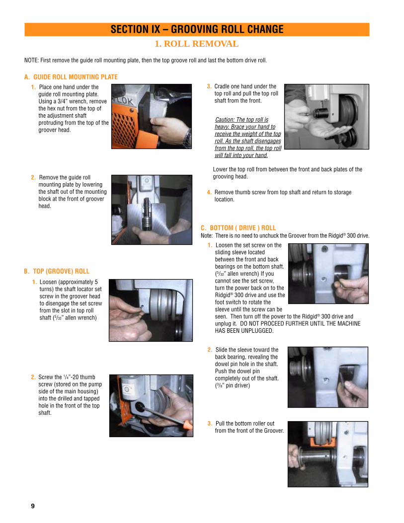
1. ROLL REMOVAL
NOTE: First remove the guide roll mounting plate, then the top groove roll and last the bottom drive roll.
A. GUIDE ROLL MOUNTING PLATE1. Place one hand under the
guide roll mounting plate.Using a 3/4” wrench, removethe hex nut from the top ofthe adjustment shaftprotruding from the top of thegroover head.
2. Remove the guide rollmounting plate by loweringthe shaft out of the mountingblock at the front of grooverhead.
SECTION IX – GROOVING ROLL CHANGE
C. BOTTOM ( DRIVE ) ROLLNote: There is no need to unchuck the Groover from the Ridgid® 300 drive.
1. Loosen the set screw on thesliding sleeve locatedbetween the front and backbearings on the bottom shaft.(5/32” allen wrench) If youcannot see the set screw,turn the power back on to theRidgid® 300 drive and use thefoot switch to rotate thesleeve until the screw can beseen. Then turn off the power to the Ridgid® 300 drive andunplug it. DO NOT PROCEED FURTHER UNTIL THE MACHINEHAS BEEN UNPLUGGED.
2. Slide the sleeve toward theback bearing, revealing thedowel pin hole in the shaft.Push the dowel pincompletely out of the shaft.(3/8” pin driver)
3. Pull the bottom roller outfrom the front of the Groover.
2. Screw the 1/4”-20 thumbscrew (stored on the pumpside of the main housing)into the drilled and tappedhole in the front of the topshaft.
3. Cradle one hand under thetop roll and pull the top rollshaft from the front.
Caution: The top roll isheavy. Brace your hand toreceive the weight of the toproll. As the shaft disengagesfrom the top roll, the top rollwill fall into your hand.
Lower the top roll from between the front and back plates of thegrooving head.
4. Remove thumb screw from top shaft and return to storagelocation.
1. Loosen (approximately 5turns) the shaft locator setscrew in the groover headto disengage the set screwfrom the slot in top rollshaft (5/32” allen wrench)
B. TOP (GROOVE) ROLL

10
SECTION IX – GROOVING ROLL CHANGE2. ROLL INSTALLATION
C. GUIDE ROLL MOUNTING PLATESelect the correct mounting plate for either steel pipe or for copper tube.
1. Insert the adjustment shaftfrom the bottom,into the holein the mounting block at thefront of the groover head.
3. Using a 3⁄4" wrench, installand snug the hex nut on thetop of the adjustment shaft.
B. TOP (GROOVE) ROLL1. Raise the groove roll
between the front and backplates of the groover head.The deep slot in the toproller should be locatedtoward the back of thegroover.
A. BOTTOM ( DRIVE ) ROLL1. Insert the bottom roll shaft
through the front of thegroover.
2. Rotate the bottom roll toalign the dowel pin hole onthe side of the machine.
3. Insert the dowel pin until itis flush with the bottomshaft surface.
4. Slide the retaining sleeveover the dowel pin hole andtighten the set screw. (5⁄32”allen wrench)
2. Insert the top shaft into thefront of the machine so thatthe V-groove is towards thefront. Push the shaft back-ward until the front isapproximately even with thefront face of the machine.
3. Tighten the locator socketsetscrew (5/32” allenwrench).This will align theV-groove with the locator setscrew in the groover head.Care should be taken toavoid contacting the plaindiameter of the shaft.
2. Slide the shaft up to exposethe threaded portion at thetop of mounting block.
11
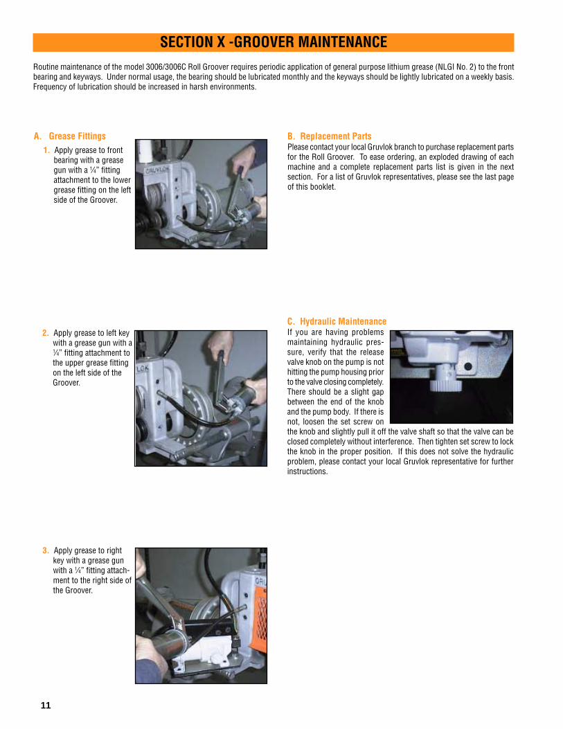
SECTION X -GROOVER MAINTENANCERoutine maintenance of the model 3006/3006C Roll Groover requires periodic application of general purpose lithium grease (NLGI No. 2) to the frontbearing and keyways. Under normal usage, the bearing should be lubricated monthly and the keyways should be lightly lubricated on a weekly basis.Frequency of lubrication should be increased in harsh environments.
A. Grease Fittings1. Apply grease to front
bearing with a greasegun with a 1⁄4” fittingattachment to the lowergrease fitting on the leftside of the Groover.
2. Apply grease to left keywith a grease gun with a1⁄4” fitting attachment tothe upper grease fittingon the left side of theGroover.
3. Apply grease to rightkey with a grease gunwith a 1⁄4” fitting attach-ment to the right side ofthe Groover.
B. Replacement PartsPlease contact your local Gruvlok branch to purchase replacement partsfor the Roll Groover. To ease ordering, an exploded drawing of eachmachine and a complete replacement parts list is given in the nextsection. For a list of Gruvlok representatives, please see the last pageof this booklet.
C. Hydraulic MaintenanceIf you are having problemsmaintaining hydraulic pres-sure, verify that the releasevalve knob on the pump is nothitting the pump housing priorto the valve closing completely.There should be a slight gapbetween the end of the knoband the pump body. If there isnot, loosen the set screw onthe knob and slightly pull it off the valve shaft so that the valve can beclosed completely without interference. Then tighten set screw to lockthe knob in the proper position. If this does not solve the hydraulicproblem, please contact your local Gruvlok representative for furtherinstructions.

12
1 1A
1B
31C
1D
1E
2 2A
2B
2C
2D 2E
2F
2G
4
56
7
8
10
11
12
14
13
9 2 Req.
2 Req.
2 Req.
2 Req.
3 Req.
2 Req.
2 Req.
3 Req.
1516
17
ID No. Part Name .............................................................. Part No.
1 Pump Assembly ....................................... GL11355The Pump Assembly consists of the following:
1A Hydraulic Pump ..................................... GL11356
1B Hydraulic Pressure Gage ....................... GL11084
1C Cap Screw, 1⁄4-20, L= 5/8" ........................ GL11093
1D Pump Plate ............................................ GL11297
1E Cap Screw, 1⁄4-20, L= 1⁄2" ......................... GL11230
2 Steel Guide Roll Assembly.......................... GL11291The Guard Assembly consists of the following:
2A Hex Nut, 1⁄2" ............................................ GL11198
2B Guide Roll Guard ................................... GL11304
2C Guide Roll ..............................................GL11106
2D Shoulder Bolt, 1⁄2" ................................... GL11107
2E Washer, 1⁄2" ............................................ GL11109
2F Flat Head Screw, 1⁄4-20, L=3⁄4" ................ GL11108
2G Cap Screw, 1⁄4-20,L= 1⁄2" ..........................GL11230
ID No. Part Name .............................................................. Part No.
3 Hex Bolt, 5⁄8-11, L= 1.5" .......................................... GL11091
4 Cap Screw, 1⁄4-20,L= 1⁄2" .......................................... GL11230
5 Safety Mesh ........................................................... GL11280
6 Hydraulic Ram ....................................................... GL11095
7 Jam Nut, 7⁄8-14 ....................................................... GL11277
8 Hex Nut, 7⁄8-14 ....................................................... GL11276
9 2-6" Steel Top Roller .............................................. GL11285
10 Cup Point Set Screw, 5⁄16-18 .................................. GL11289
11 Dowel Pin .............................................................. GL11290
12 Cone Pt. Set Screw, 5⁄16-18 ..................................... GL11282
13 2-6" Steel Bottom Roller ........................................ GL11284
14 Top Shaft ............................................................... GL11281
15 8-12" Steel Bottom Roller ...................................... GL11299
16 8-12" Steel Top Roller ............................................ GL11300
17 Thumb Screw 1⁄4 - 20, L=1" ..................................... GL11056
Support Leg Assembly .......................................... GL11374
SECTION XI - REPLACEMENT PARTS LIST – 3006

ID No. Part Name .............................................................. Part No.
3 Hex Bolt, 5⁄8-11, L=1.5" ........................................... GL11091
4 Cap Screw, 1⁄4-20,L= 1⁄2" .......................................... GL11230
5 Safety Mesh ........................................................... GL11280
6 Hydraulic Ram ....................................................... GL11095
7 Jam Nut, 7⁄8-14 ....................................................... GL11277
8 Hex Nut, 7⁄8-14 ....................................................... GL11276
9 2-6" Copper Top Roller .......................................... GL11122
10 Cup Point Set Screw, 5⁄16-18 ................................. GL11289
11 Dowel Pin .............................................................. GL11290
12 Cone Pt. Set Screw, 5⁄16-18 .................................... GL11282
13 2-6" Copper Bottom Roller ..................................... GL11349
14 Top Shaft ............................................................... GL11281
15 Thumb Screw 1⁄4-20, L=1" ...................................... GL11056
16 Universal 2-6" Diameter Gage ................................ GL11133
Support Leg Assembly .......................................... GL11374
13
1
1A
1B
3 1C
1D
1E
2
2A
2B
2C
2H
2D 2E
2F
2G
4
56
7
8
10
11
12 14
13
9 2 Req.
2 Req.
2 Req.
2 Req.
3 Req.
2 Req.
2 Req.
3 Req.
16
15
ID No. Part Name .............................................................. Part No.
1 Pump Assembly ....................................... GL11355The Pump Assembly consists of the following:
1A Hydraulic Pump ..................................... GL11356
1B Hydraulic Pressure Gage ....................... GL11084
1C Cap Screw, 1⁄4-20, L= 5⁄8 ............................................ GL11093
1D Pump Plate ............................................ GL11297
1E Cap Screw, 1⁄4-20, L= 1⁄2" ......................... GL11230
2 Copper Guide Roll Assembly ....................... GL11352The Guide Assembly consists of the following:
2A Hex Nut, 1⁄2" ............................................ GL11198
2B Guide Roll Guard ................................... GL11304
2C Guide Roll .............................................. GL11106
2D Shoulder Bolt, 1⁄2" ................................... GL11107
2E Washer, 1⁄2" ............................................ GL11109
2F Flat Head Screw, 1⁄4-20, L= 3⁄4" ................ GL11108
2G Cap Screw, 1⁄4-20, L= 1⁄2" ......................... GL11230
2H C-Clip .................................................... GL11078
SECTION XI - REPLACEMENT PARTS LIST – 3006C

14
COLUMN 1: Nominal IPS Pipe size.
COLUMN 2: IPS outside diameter.
COLUMN 3: Gasket seat must be free fromscores, seams, chips, rust or scalewhich may interfere with propersealing of the gasket. Gasket seatwidth is to be measured from thepipe end to the vertical flank in thegroove wall.
COLUMN 4: Groove width is to be measuredbetween vertical flank of thegroove size walls
COLUMN 5: The groove must be of uniformdepth around theentire pipe circumference. (Seecolumn 6).
COLUMN 6: Groove depth: for reference only.Groove must conform to thegroove diameter “C” listed in col-umn 5.
COLUMN 7: Minimum allowable wall thicknesswhich may be roll grooved.
COLUMN 8: Maximum allowable pipe end flarediameter. Measured at the mostextreme pipe end diameter of thegasket seat area.
GRUVLOK STANDARD ROLL GROOVE SPECIFICATION
FOR STEEL & OTHER IPS-1- -2- -3- -4- -5- -6- -7- -8-
Gasket Groove Groove Min.Seat Width Diameter Groove Allow.
Nominal "A" “B” “C” Depth Wall Max.IPS Pipe Pipe OD ±0.030 ±0.030 Tol. "D" Thick. Flare
Size Actual Tolerance ±0.76 ±0.76 Actual +0.000 (Ref. Only) "T" Dia.In./DN(mm) In./mm +In./mm-In./mm In./mm In./mm In./mm-In./mm In./mm In./mm In./mm
2 2.375 +0.024 -0.024 0.625 0.344 2.250 -0.015 0.063 0.065 2.48050 60.3 +0.61 -0.61 15.88 8.74 57.15 -0.38 1.60 1.7 63.021⁄2 2.875 +0.029 -0.029 0.625 0.344 2.720 -0.018 0.078 0.083 2.98065 73.0 +0.74 -0.74 15.88 8.74 69.09 -0.46 1.98 2.1 75.73 3.500 +0.035 -0.031 0.625 0.344 3.344 -0.018 0.078 0.083 3.60080 88.9 +0.89 -0.79 15.88 8.74 84.94 -0.46 1.98 2.1 91.431⁄2 4.000 +0.040 -0.031 0.625 0.344 3.834 -0.020 0.083 0.083 4.10090 101.6 +1.02 -0.79 15.88 8.74 97.38 -0.51 2.11 2.1 104.14 4.500 +0.045 -0.031 0.625 0.344 4.334 -0.020 0.083 0.083 4.600
100 114.3 +1.14 -0.79 15.88 8.74 110.08 -0.51 2.11 2.1 116.85 5.563 +0.056 -0.031 0.625 0.344 5.395 -0.022 0.084 0.109 5.660
125 141.3 +1.42 -0.79 15.88 8.74 137.03 -0.56 2.13 2.8 143.86 6.625 +0.063 -0.031 0.625 0.344 6.455 -0.022 0.085 0.109 6.730
150 168.3 +1.60 -0.79 15.88 8.74 163.96 -0.56 2.16 2.8 170.98 8.625 +0.063 -0.031 0.750 0.469 8.441 -0.025 0.092 0.109 8.800
200 219.1 +1.60 -0.79 19.05 11.91 214.40 -0.64 2.34 2.8 223.510 10.750 +0.063 -0.031 0.750 0.469 10.562 -0.027 0.094 0.134 10.920250 273.1 +1.60 -0.79 19.05 11.91 268.27 -0.69 2.39 3.4 277.412 12.750 +0.063 -0.031 0.750 0.469 12.531 -0.030 0.109 0.156 12.920300 323.9 +1.60 -0.79 19.05 11.91 318.29 -0.76 2.77 4.0 328.2
• Out of roundness: Difference between maximum OD and minimum OD measured at90° must not exceed total OD tolerance listed.
• For IPS pipe, the maximum allowable tolerance from square cut ends is 0.03" for 2"thru 31⁄2"; 0.045" for 4" thru 6"; and 0.060" for sizes 8" and above measured from a truesquare line.
• Beveled End Pipe in conformance with ANSI B16.25 (371⁄2°) is acceptable, howeversquare cut is preferred.
SECTION XII – GROOVE SPECIFICATIONSGRUVLOK® ROLL GROOVE SPECIFICATIONS

15
COLUMN 1: Nominal ASTM B88 copper tubing size.
COLUMN 2: Outside diameter of copper tubing in accordance with ASTM B88.
COLUMN 3: Outside diameter of Copper Prep roll grooved copper tubing.
COLUMN 4: Gasket seat and groove must be free from scores, seams, chips, or corrosion which may interfere with propercoupling assembly.
COLUMN 5: Groove width is to be measured between vertical flank of the groove size walls.
COLUMN 6: The groove must be of uniform depth around the entire tubing circumference. (See column 7).
COLUMN 7: Groove depth: for reference only. Groove must conform to the groove diameter “C” listed in column 6.
COLUMN 8: Minimum allowable copper tube wall thickness which may be prepared to Gruvlok Copper-Prep specifications.
COLUMN 9: Maximum allowable end flare diameter. Measured at the most extreme tubing end diameter of the gasket seat area.
Notes: • Out of roundness: Difference between maximum OD and minimum OD measured at 90° must not exceed tolerance listed.• The maximum allowable tolerance from square cut ends is 0.030" for 2" thru 3" and 0.045" for 4" thru 6"; measured from a true square line.
GRUVLOK COPPER PREP ROLL GROOVE SPECIFICATIONS FOR TYPES K, L, M AND DWV COPPER TUBING-1- -2- -3- -4- -5- -6- -7- -8- -9-
Gasket Groove AllowSeat A Width B Groove Diameter "C" Groove Wall Max.
Nominal Tubing Outside Diameter Tube End Connection Diameter ± .030 ± .030 Tol. Depth D Thick FlareTubing Size Actual Tolerance Actual Tolerance ± .77 ± .77 Actual +0.000 (Ref. Only) T Dia.In./DN(mm) In./mm +In./mm–In./mm In./mm +In./mm–In./mm In./mm In./mm In./mm –In./mm In./mm In./mm In./mm
2 2.125 0.002 0.002 2.375 0.045 0.024 0.625 0.344 2.250 -0.015 0.063 0.059 2.44750 54.0 0.05 0.05 60.33 1.14 0.61 15.88 8.74 57.15 -0.381 1.60 1.50 62.15
2 1/2 2.625 0.002 0.002 2.875 0.029 0.029 0.625 0.344 2.720 -0.018 0.077 0.065 2.96265 66.7 0.05 0.05 73.03 0.74 0.74 15.88 8.74 69.09 -0.46 1.96 1.65 75.233 3.125 0.002 0.002 3.500 0.035 0.031 0.625 0.344 3.344 -0.018 0.078 DWV 3.56680 79.4 0.05 0.05 88.90 0.89 0.79 15.88 8.74 84.94 -0.46 1.98 90.584 4.125 0.002 0.002 4.500 0.045 0.031 0.625 0.344 4.334 -0.020 0.083 DWV 4.576
100 104.8 0.05 0.05 114.30 1.14 0.79 15.88 8.74 110.08 -0.51 2.11 116.235 5.125 0.002 0.002 5.562 0.056 0.031 0.625 0.344 5.395 -0.022 0.084 DWV 5.650
125 130.2 0.05 0.05 141.27 1.42 0.79 15.88 8.74 137.03 -0.56 2.13 143.516 6.125 0.002 0.002 6.625 0.063 0.031 0.625 0.344 6.455 -0.022 0.085 DWV 6.719
150 155.6 0.05 0.05 168.28 1.60 0.79 15.88 8.74 163.96 -0.56 2.16 170.66
SECTION XII – GROOVE SPECIFICATIONS
BA T
C
D
GRUVLOK® COPPER-METHOD: COPPER PREP SPECIFICATIONS

16
1. Pipe will not stay in grooving rolls Incorrect pipe positioning.
Improper grooving technique.
Power drive running counterclockwiseModel 3006 / 3007 & 1007.
See "Pipe Set-up & Positioning
See "Grooving Pipe"
Rigid 300 check setting in reverseClockwise rotation of pipe
2. Pipe stops rotating during grooving. Rust or dirt has built up on lower roll.
Worn grooving rolls.
Bottom roll dowel pin is sheared or missing.
Rigid 300 chuck jaws not engaged properly.
Steel Pipe – Groove Diameter Stop improperly adjusted.
Copper Pipe – Groove Diameter Stopmaking contact with top surface of Groover.
Remove accumulation fromlower roll with stiff wire brush.
Inspect lower rolls for wornknurls, replace if worn.
Replace dowel pin per instructionsin Section IX.
See "Groover Set-up"
Adjust Groove Diameter Stop tocorrect IPS.
Verify Groove Diameter Stop Nutsare fully backed off.
Pipe stand adjusted too high.
Tool is tilted forward.
Incorrect pipe stand offset positioning.Pipe is over "tracking".
Warped drive shaft.
3. Pipe flare excessive See "Pipe Set-up & Positioning"
See "Groover Set-up"
See "Pipe Set-up & Positioning"
The rear collar of the drive shaftis missing. Replace damaged parts.
Pipe or Tube not square cut.
Incorrect pipe roller offset positioningPipe is over "tracking".
4. While grooving loud squeaks echothrough the pipe.
5. During grooving loud thumps or bangs occur about once every revolution of the pipe.
Pipe has a pronounced weld seam.
6. Tool won't groove pipe. Hand pump is low on oil.
Air in hydraulic system.
Pipe wall thickness exceeds tool's capability.
Cut pipe or tube ends squarely.
Move pipe stand for proper offset.See "Pipe Set-up & Positioning
Grind welds flush with pipesurface inside & out 2" backfrom pipe end.
See "Groover Maintenance"
See "Groover Maintenance"
See "Groover Description"
TROUBLESHOOTING INSTRUCTIONSProblem Possible Cause Solution
SECTION XIII - TROUBLESHOOTING

17
NOTES

NOTES

ANVIL MANAGEMENT TEAM
Thomas E. Fish PresidentKen Dangelmaier Vice President, Sales and Marketing
Bob Arison Regional Vice PresidentHugh Brennan Regional Vice PresidentErnie Chuter Director, MarketingLaura DiLiegro Director, Human ResourcesJohn Martin Vice President, National AccountsLeigh Porter Regional Vice PresidentRon Pound Director, National OperationsWilliam Strouss Vice President, FinanceTom Ward Regional Vice President
ANVIL MANUFACTURED PRODUCTS
Statesboro, GA Foundry11021 Clito RoadStatesboro, GA 30459Tel: 912-587-2212 • 912-587-2261Bob Kim — Plant Manager
Columbia, PA Foundry1411 Lancaster AvenueColumbia, PA 17512Tel: 717-684-4400 • Fax: 717-684-6868Paul Benos— Plant Manager
Henderson, TN Plant2870 Old Jackson RoadHenderson, TN 38340Tel: 901-989-3551 • Fax: 901-989-4144Rich Brooks — Plant Manager
Canvil390 Second AvenueSimcoe, ON Canada N3Y 4K9Tel: 519-426-4551 • Fax: 519-426-5509Brent Widdifield — Plant Manager
Longview, TX Plant305 SimmsLongview, TX 75604Tel: 903-759-4417 • 903-759-1782Van O’Keefe — Plant Manager
J.B. Smith6618 NavigationHouston, TX 77011Tel: 713-928-5460 • 713-928-6733Ray Mullenix — Plant Manager
North Kingstown, RI Plant160 Frenchtown RoadNorth Kingstown, RI 02852Tel: 401-886-3001 • Fax: 401-886-3010Robert Taylor — Plant Manager
ENGINEERED PIPE SUPPORTS• Structural Fabrication• Field Services• Non-destructive Testing
Contact: North Kingstown, RI Plant401-886-3001
ANVIL RESEARCH AND DEVELOPMENT20 Thurber Blvd.Smithfield, RI 02917Tel: 401-349-3020Fax: 401-349-3021
ANVIL NATIONAL ACCOUNTSJohn Martin – Vice President National AccountsTel: 303-394-2856Fax: 303-394-3520
NORTH EAST REGIONRegional Service Center: Servicing Connecticut,Delaware, Maine, Maryland, Massachusetts,New Hampshire, New Jersey, New York,East Pennsylvania, Rhode Island, Vermont2530 Pearl Buck RoadBristol, PA 19007Tel: 215-788-4056 • Fax: 215-788-4475Tom Ward — Regional Vice President
Sales Offices792 S. Main StreetMansfield, MA 02048Tel: 508-261-4050 • Fax: 508-261-4046
1234 Route 23 NorthButler, NJ 07405Tel: 973-696-0600 • Fax: 973-696-5124
SOUTH EAST REGIONRegional Service Center: Servicing Alabama,Florida, Georgia, Mississippi, North Carolina,South Carolina, Tennessee, Virginia6344 Cash CourtNorcross, GA 30071Tel: 770-662-8177 • Fax: 770-662-0284Tom Ward — Regional Vice President
Sales Offices5019 Nation's Crossing, Suite 218Charlotte, NC 28217Tel: 704-525-8195, 8196, 8197 • Fax: 704-525-8198
1202 Tech Blvd., Suite 103Tampa, FL 33619Tel: 800-429-0703 • Fax: 813-663-0811
MID WEST REGIONRegional Service Center: Servicing Illinois, Indiana,Iowa, Kansas, Kentucky, Michigan, Minnesota, Missouri,Nebraska, North Dakota, Ohio, West Pennsylvania, SouthDakota, West Virginia, Wisconsin750 Central AvenueUniversity Park, IL 60466Tel: 708-534-1414 • Fax: 708-534-5441Toll Free: 1-800-301-2701Hugh Brennan — Regional Vice President
Sales Office321 North Point DrivePittsburgh, PA 15233Tel: 412-321-6544 • Fax: 412-321-6643Toll Free: 1-800-441-1352
Satellite Offices1201 W. 96th StreetBloomington, MN 55341Tel: 952-884-7131 • Fax: 952-887-1501Toll Free: 1-800-733-7131
9530 Le Saint DriveFairfield, OH 45104Tel: 513-682-2330 • Fax: 513-870-0109Toll Free: 1-800-837-2424
8615 East 33rd StreetIndianapolis, IN 46226Tel: 317-895-2424 • Fax: 317-895-2430Toll Free: 1-800-837-1515
1930 Warren StreetKansas City, MO 64116Tel: 816-474-0500 • Fax: 816-221-7150Toll Free: 1-800-877-7007
21655 Trolley Industrial DriveTaylor, MI 48180Tel: 313-292-3800 • Fax: 313-292-1821
SOUTH WEST REGIONRegional Service Center: Servicing Arkansas,Arizona, Colorado, Louisiana, New Mexico, Oklahoma,Texas, Utah, Wyoming1313 Avenue RGrand Prairie, TX 75050Tel: 972-343-9206 • Fax: 972-641-8946Bob Arison — Regional Vice President
Sales Office6999 Old Clinton RdHouston, TX 77001Tel: 713-675-6371 • Fax: 713-678-7858
Satellite Office2600 W. 42nd StreetOdessa, TX 79764Tel: 915-366-2803 • Fax: 915-366-0890
3131 W. Thomas RoadPhoenix, AZ 85017Tel: 602-272-6535 • Fax: 602-278-3792
4200 Holly StreetDenver, CO 80216Tel: 303-394-2178 • Fax: 303-321-3050
WESTERN REGIONRegional Service Center: Servicing Alaska, California,Hawaii, Idaho, Montana, Nevada, Oregon, Washington1600 E. Orangethorpe AvenueFullerton, CA 92831Tel: 714-773-1166 • Fax: 714-879-2319Leigh Porter — Regional Vice President
Sales Offices3240 Northwest 29th AvenuePortland, OR 97210Tel: 503-223-7101 • Fax: 503-223-7130
1600 Sacramento Inn Way, Suite 202Sacramento, CA 95185Tel: 916-641-0166 • Fax: 916-641-0560
Satellite Offices23285 "A" Eichler StreetHayward, CA 94545-2750Tel: 510-887-8700 • Fax: 510-887-6815
8212 S. 196th StreetKent, WA 98032Tel: 425-251-9585 • Fax: 425-251-5489
CANADA — MUELLER-FLOW CONTROLDavid A. Read — Vice President • 416-251-4171
AlbertaCalgary – Tel: 403-246-0033 • Fax: 403-246-0051Edmonton – Tel: 780-452-9841 • Fax: 780-452-9873
British ColumbiaDelta – Tel: 604-940-1449 • Fax: 604-940-9878Nanaimo – Tel: 250-758-1551 • Fax: 250-758-1160Prince George – Tel: 250-561-1219 • Fax: 250-561-7358Vancouver City – Tel: 604-875-6990 • Fax: 604-875-6962
ManitobaWinnipeg – Tel: 204-774-3461 • Fax: 204-786-5044
OntarioStoney Creek – Tel: 905-664-9230 • Fax: 906-664-9556Toronto – Tel: 416-251-4171 • Fax: 416-251-7087Sarnia – Tel: 519-336-7690 • Fax: 519-336-1621Sudbury – Tel: 705-671-9600 • Fax: 705-671-8082
QuebecMontreal – Tel: 514-342-2100 • Fax: 514-342-2177Ste-Foy – Tel: 418-650-5766 • Fax: 418-266-0252
SaskatchewanRegina – Tel: 306-543-5536 • Fax: 306-545-0390Saskatoon – Tel: 306-242-6788 • Fax: 306-242-5089
Corporate Offices110 Corporate Drive, Suite 10P.O. Box 3180Portsmouth, NH 03802-3180Tel: 603-422-8000 • Fax: 603-422-8033E-mail address — [email protected]
#117/ Printed in USA / RPI / 5M / ©2001