antenna characterization for wireless power- transmission ... · pdf file108 ieee antennas and...
TRANSCRIPT

108 IEEE Antennas and Propagation Magazine, Vol. 54, No. 4, August 2012
Antenna Characterization for Wireless Power-Transmission System Using
Near-Field Coupling
Qiang Chen1, Kazuhiro Ozawa1, Qiaowei Yuan2, and Kunio Sawaya1
1Department of Electrical and Communication Engineering, Graduate School of EngineeringTohoku University
Aramaki Aza Aoba 6-6-05, Aoba-ku, Sendai, 980-8579 JapanTel: +81-22-795-7097; E-mail: [email protected]; [email protected]
2Sendai National College of TechnologyMiyagi, Japan
E-mail: [email protected]
Abstract
A fundamental study was focused on the investigation of wireless power transmission by near-fi eld coupling from the view point of the antennas. Two types of antennas – dipole and loop antennas – were used as the transmitting antenna and the receiving antenna for electrical near-fi eld coupling and for magnetic near-fi eld coupling, respectively. The relationships among the power-transmission effi ciency and the antennas’ geometries, the antennas’ electrical sizes, the impedance matching of the antennas, and the ohmic losses in the antennas and the impedance-matching circuits were clarifi ed. Several observations were obtained, demonstrating the infl uence on the power-transmission effi ciency of the impedance matching and ohmic losses in the wireless power-transmission system associated with near-fi eld coupling.
Keywords: Electromagnetic induction; power transmission; electromagnetic coupling; antennas; impedance matching; wireless power transmission; wireless power transfer
1. Introduction
Studies on wireless power transmission (WPT) started as early as 100 years ago. Reinhold Rudenberg described the
funda mental theory of electric power absorption by antennas early in 1908 [1]. Nikola Tesla developed the fi rst practical wireless power-transmission system in 1904 [2], and revealed the sys tem confi guration in his US patent in 1914 [3]. Since then, there have been numerous research efforts involving both fun-damental and applied studies on wireless power transmission. This technology has been widely applied, from the wireless charging of electronic devices to huge projects, such as the solar-power satellite (SPS) system [4]. However, this technol-ogy still has some problems. One of the most pressing chal-lenges is how to maintain higher power-transmission effi ciency (PTE) over longer transmission distances.
Recently, it was experimentally demonstrated that very effi cient power transmission can be achieved by using the
so-called evanescent resonant-coupling method, showing its potential for practical application [5]. It was shown that the evanescent resonant-coupling method can transmit energy for a longer distance than the previously used near-fi eld induction method [6, 7]. The evanescent resonant-coupling method was shown to be more effi cient than the far-fi eld radiation method, wherein the vast majority of the energy was wasted, due to the transmission loss [8-10].
There have been many research studies following [5]. In [11], the power-transmission effi ciencies of two dielectric disks and two capacitively loaded conducting-wire loops were calculated from the resonance width and the coupling coeffi -cient based on the coupled-mode theory. This showed the applicability of a wireless power-transmission system in the presence of extraneous environmental objects. Wireless power transmission via magnetic resonant coupling was experimen-tally demonstrated in a system with a large source coil and either one or two small receivers. Resonance between the source and
load coils was achieved with lumped capacitors terminating the coils [12]. It was also demonstrated that a wireless power-transmission system could be designed by conventional circuit theory and multistage fi lter theory in [13, 14]. We presented a practical wireless power-transmission system consisting of a large wire loop and a small wire loop with a parasitic square helical coil for an indoor application. We investigated the variation of the power-transmission effi ciency when the location of the small loops was changed, and the resonance condition was destroyed by nearby scattering objects [15].
This research was focused on a wireless power-transmis-sion system using near-fi eld coupling to unify the concept of the evanescent resonant-coupling method and the conventional near-fi eld induction method. The study was performed from the viewpoint of antenna theory instead of circuit theory. This was done by investigating antenna parameters such as the geometry of the transmitting and receiving antennas, the elec trical size of the antennas, impedance matching for the anten nas, the distance between the transmitting and receiving antennas, the conductor loss (ohmic loss) of the antennas, the ohmic loss of the matching circuits, and so on, in order to clarify the relationships among the power-transmission effi ciency and these parameters. Two types of antennas, dipole antennas and loop antennas, were used as conical models to obtain some general conclusions. The power-transmission effi ciency was strictly defi ned as the ratio of the received power at the receiving antenna and the input power at the transmitting antenna. The input impedance of the antennas, including the effects of near-fi eld coupling between the trans-mitting and receiving antennas, was completely considered in evaluating the power-transmission effi ciency. The study was performed using a full-wave EM analysis based on the Method of Moments (MoM).
2. Analysis Model and Method
In order to obtain a clear physical explanation of the rela-tionship between the power-transmission effi ciency and the antenna parameters, two simple antennas were used as the transmitting and receiving antennas. These were a straight wire dipole with a length l , shown in Figure 1, and a circular wire loop with a diameter of D , shown in Figure 2, operating as the antennas for electric coupling and magnetic coupling, respectively. The transmitting and receiving antennas were the same, and were separated by a distance d . The transmitting antenna was connected to a source with an internal impedance of sZ , while the receiving antenna was loaded with an imped-ance lZ .
These two wireless power-transmission systems can be expressed in the form of a two-port equivalent circuit, shown in Figure 3. The power-transmission effi ciency can be evalu ated by using the S parameters of the circuit as
( )( )
2221
2 222
1
1 1
ll
in l in
SPP S
η− Γ
= =− Γ − Γ
, (1)
Figure 1. A wireless power-transmission system using dipole antennas.
Figure 2. A wireless power-transmission system using loop antennas.
Figure 3. The two-port equivalent circuit for the analysis of a wireless power-transmission system.
ISSN 1045-9243/2012/$26 ©2012 IEEE
AP_Mag_Aug_2012_Final.indd 108 9/3/2012 4:38:01 AM

IEEE Antennas and Propagation Magazine, Vol. 54, No. 4, August 2012 109
Antenna Characterization for Wireless Power-Transmission System Using
Near-Field Coupling
Qiang Chen1, Kazuhiro Ozawa1, Qiaowei Yuan2, and Kunio Sawaya1
1Department of Electrical and Communication Engineering, Graduate School of EngineeringTohoku University
Aramaki Aza Aoba 6-6-05, Aoba-ku, Sendai, 980-8579 JapanTel: +81-22-795-7097; E-mail: [email protected]; [email protected]
2Sendai National College of TechnologyMiyagi, Japan
E-mail: [email protected]
Abstract
A fundamental study was focused on the investigation of wireless power transmission by near-fi eld coupling from the view point of the antennas. Two types of antennas – dipole and loop antennas – were used as the transmitting antenna and the receiving antenna for electrical near-fi eld coupling and for magnetic near-fi eld coupling, respectively. The relationships among the power-transmission effi ciency and the antennas’ geometries, the antennas’ electrical sizes, the impedance matching of the antennas, and the ohmic losses in the antennas and the impedance-matching circuits were clarifi ed. Several observations were obtained, demonstrating the infl uence on the power-transmission effi ciency of the impedance matching and ohmic losses in the wireless power-transmission system associated with near-fi eld coupling.
Keywords: Electromagnetic induction; power transmission; electromagnetic coupling; antennas; impedance matching; wireless power transmission; wireless power transfer
1. Introduction
Studies on wireless power transmission (WPT) started as early as 100 years ago. Reinhold Rudenberg described the
funda mental theory of electric power absorption by antennas early in 1908 [1]. Nikola Tesla developed the fi rst practical wireless power-transmission system in 1904 [2], and revealed the sys tem confi guration in his US patent in 1914 [3]. Since then, there have been numerous research efforts involving both fun-damental and applied studies on wireless power transmission. This technology has been widely applied, from the wireless charging of electronic devices to huge projects, such as the solar-power satellite (SPS) system [4]. However, this technol-ogy still has some problems. One of the most pressing chal-lenges is how to maintain higher power-transmission effi ciency (PTE) over longer transmission distances.
Recently, it was experimentally demonstrated that very effi cient power transmission can be achieved by using the
so-called evanescent resonant-coupling method, showing its potential for practical application [5]. It was shown that the evanescent resonant-coupling method can transmit energy for a longer distance than the previously used near-fi eld induction method [6, 7]. The evanescent resonant-coupling method was shown to be more effi cient than the far-fi eld radiation method, wherein the vast majority of the energy was wasted, due to the transmission loss [8-10].
There have been many research studies following [5]. In [11], the power-transmission effi ciencies of two dielectric disks and two capacitively loaded conducting-wire loops were calculated from the resonance width and the coupling coeffi -cient based on the coupled-mode theory. This showed the applicability of a wireless power-transmission system in the presence of extraneous environmental objects. Wireless power transmission via magnetic resonant coupling was experimen-tally demonstrated in a system with a large source coil and either one or two small receivers. Resonance between the source and
load coils was achieved with lumped capacitors terminating the coils [12]. It was also demonstrated that a wireless power-transmission system could be designed by conventional circuit theory and multistage fi lter theory in [13, 14]. We presented a practical wireless power-transmission system consisting of a large wire loop and a small wire loop with a parasitic square helical coil for an indoor application. We investigated the variation of the power-transmission effi ciency when the location of the small loops was changed, and the resonance condition was destroyed by nearby scattering objects [15].
This research was focused on a wireless power-transmis-sion system using near-fi eld coupling to unify the concept of the evanescent resonant-coupling method and the conventional near-fi eld induction method. The study was performed from the viewpoint of antenna theory instead of circuit theory. This was done by investigating antenna parameters such as the geometry of the transmitting and receiving antennas, the elec trical size of the antennas, impedance matching for the anten nas, the distance between the transmitting and receiving antennas, the conductor loss (ohmic loss) of the antennas, the ohmic loss of the matching circuits, and so on, in order to clarify the relationships among the power-transmission effi ciency and these parameters. Two types of antennas, dipole antennas and loop antennas, were used as conical models to obtain some general conclusions. The power-transmission effi ciency was strictly defi ned as the ratio of the received power at the receiving antenna and the input power at the transmitting antenna. The input impedance of the antennas, including the effects of near-fi eld coupling between the trans-mitting and receiving antennas, was completely considered in evaluating the power-transmission effi ciency. The study was performed using a full-wave EM analysis based on the Method of Moments (MoM).
2. Analysis Model and Method
In order to obtain a clear physical explanation of the rela-tionship between the power-transmission effi ciency and the antenna parameters, two simple antennas were used as the transmitting and receiving antennas. These were a straight wire dipole with a length l , shown in Figure 1, and a circular wire loop with a diameter of D , shown in Figure 2, operating as the antennas for electric coupling and magnetic coupling, respectively. The transmitting and receiving antennas were the same, and were separated by a distance d . The transmitting antenna was connected to a source with an internal impedance of sZ , while the receiving antenna was loaded with an imped-ance lZ .
These two wireless power-transmission systems can be expressed in the form of a two-port equivalent circuit, shown in Figure 3. The power-transmission effi ciency can be evalu ated by using the S parameters of the circuit as
( )( )
2221
2 222
1
1 1
ll
in l in
SPP S
η− Γ
= =− Γ − Γ
, (1)
Figure 1. A wireless power-transmission system using dipole antennas.
Figure 2. A wireless power-transmission system using loop antennas.
Figure 3. The two-port equivalent circuit for the analysis of a wireless power-transmission system.
AP_Mag_Aug_2012_Final.indd 109 9/3/2012 4:38:01 AM
110 IEEE Antennas and Propagation Magazine, Vol. 54, No. 4, August 2012
where lΓ is the refl ection coeffi cient at the load lZ , and inΓ is the refl ection coeffi cient at Port 1, expressed as
0
0
ll
l
Z ZZ Z
−Γ =
+ (2)
and
12 2111
221l
inl
S SS
SΓ
Γ = +− Γ
, (3)
respectively. Here, 11S , 21S , 12S , and 22S were calculated by using the MoM, and a characteristic impedance 0 50 Z = Ω was assumed in the calculation.
3. Power-Transmission Effi ciency for the Case of Conjugate Impedance Matching
In this section, the ohmic loss of antennas was ignored, to simplify the investigation. As a result, there were two kinds of power losses left in the wireless power-transmission system: the refl ection loss, and the radiation loss. When the antennas’ geometries and the distance between antennas are given, the radiation loss is determined. In this case, if both the transmit-ting and receiving antennas were perfectly impedance-matched with the feeding circuit and load impedance, respec tively, the power-transmission effi ciency reached the maxi mum value. The perfect impedance match was realized when the condition of complex-conjugate matching was satisfi ed at both Port 1 and Port 2. Because the transmitting antenna and receiving antenna are the same, the condition of conjugate impedance matching at two ports is equivalent to the relation
in lZ Z∗= , (4)
where inZ is the input impedance at Port 1, infl uenced by the
reception port through near-fi eld coupling, and lZ∗ is the com-plex conjugate of the load impedance, lZ , at the reception port.
Because inZ depends on lZ , lZ should be tuned to a value olZ
to satisfy the relation of Equation (4). olZ is called the optimal
load impedance, and is dependent on the antenna geometry and distance between the transmitting and receiving antennas.
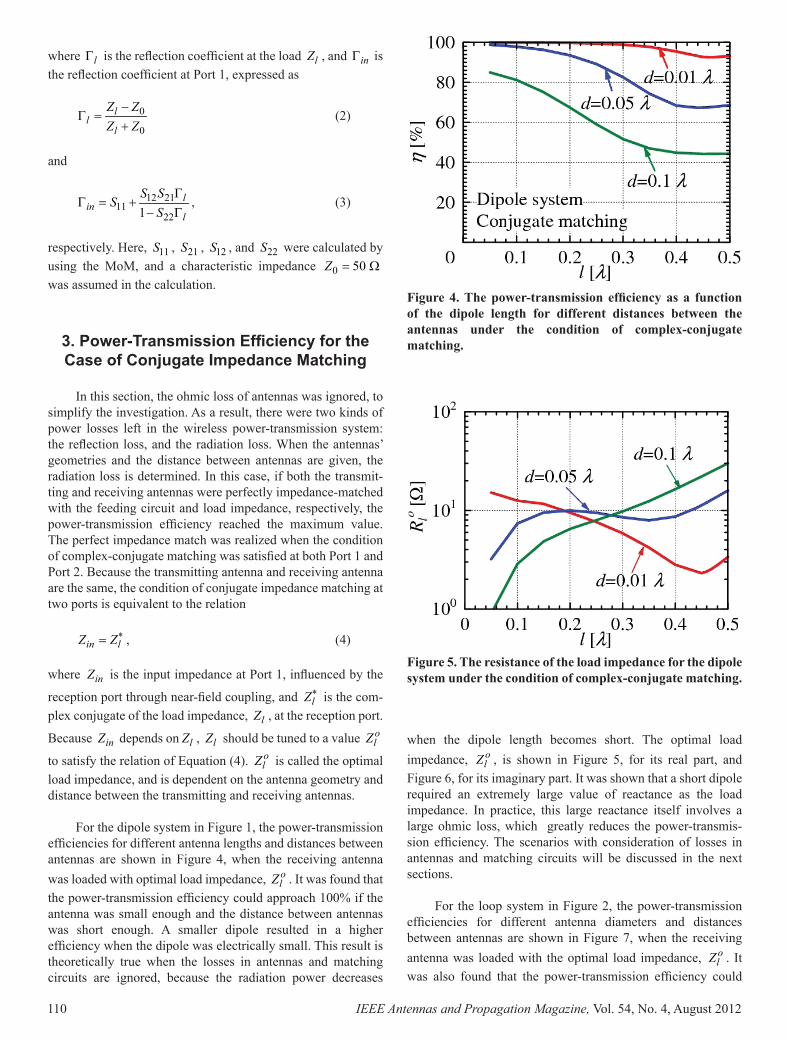
For the dipole system in Figure 1, the power-transmis sion effi ciencies for different antenna lengths and distances between antennas are shown in Figure 4, when the receiving antenna was loaded with optimal load impedance, o
lZ . It was found that the power-transmission effi ciency could approach 100% if the antenna was small enough and the distance between antennas was short enough. A smaller dipole resulted in a higher effi ciency when the dipole was electrically small. This result is theoretically true when the losses in antennas and matching circuits are ignored, because the radiation power decreases
Figure 4. The powertransmission effi ciency as a function of the dipole length for different distances between the antennas under the condition of complex-conjugate matching.
when the dipole length becomes short. The optimal load impedance, o
lZ , is shown in Figure 5, for its real part, and Figure 6, for its imaginary part. It was shown that a short dipole required an extremely large value of reactance as the load impedance. In practice, this large reactance itself involves a large ohmic loss, which greatly reduces the power-transmis-sion effi ciency. The scenarios with consideration of losses in antennas and matching circuits will be discussed in the next sections.
For the loop system in Figure 2, the power-transmission effi ciencies for different antenna diameters and distances between antennas are shown in Figure 7, when the receiving antenna was loaded with the optimal load impedance, o
lZ . It was also found that the power-transmission effi ciency could
Figure 5. The resistance of the load impedance for the dipole system under the condition of complex-conjugate matching.
approach almost 100% if the loop was small enough and the distance between antennas was short enough. A smaller loop results in a higher effi ciency when the loop is electrically small, approximately / 2D λ π≤ . As was the same with the dipole case, a large value of the reactance component of o
lZ was required to obtain a high effi ciency near 100% by using electrically small loop antennas. Compared with the dipole system, the effi ciency of both antennas had almost the same dependence on the antennas’ sizes, except for a little decrease for the loop antenna, due to its anti-resonance.
It was known from the above results that near-fi eld cou-pling for both the electrical-coupling approach and the mag-netic-coupling approach could result in a power-transmission effi ciency as high as almost 100%, if the antennas were elec-trically small enough and the distance between antennas was short enough. The concept of resonance was not necessary, but
the conjugate-matching condition was essential for realizing a high power-transmission effi ciency.
Generally speaking, a larger area of the near fi eld, which contains the non-radiated inductive fi eld, causes a longer dis-tance for power transmission with a high effi ciency. The area of the near fi eld is determined by the antennas’ geometries and the antennas’ sizes. Therefore, we investigated the dependence of the power-transmission effi ciency on the distance between antennas normalized by the physical size of the antennas for both dipoles and loops, to fi nd which type of antenna was better in keeping a high power-transmission effi ciency for a long transmission distance. The results are shown in Figure 8 for dipoles and Figure 9 for loops, where the distance between antennas, d , was normalized by the dipole’s length, l , and by the loop’s diameter, D , respectively.
Figure 6. The reactance of the load impedance for the dipole system under the condition of complex-conjugate matching.
Figure 7. The powertransmission effi ciency as a function of the loop diameter for different distances between the antennas under the condition of complex-conjugate matching.
Figure 8. The powertransmission effi ciency as a function of the distance between the antennas normalized by the antenna’s size for the dipole antenna system.
Figure 9. The powertransmission effi ciency as a function of the distance between the antennas normalized by the antenna’s size for the loop antenna system.
AP_Mag_Aug_2012_Final.indd 110 9/3/2012 4:38:01 AM

IEEE Antennas and Propagation Magazine, Vol. 54, No. 4, August 2012 111
where lΓ is the refl ection coeffi cient at the load lZ , and inΓ is the refl ection coeffi cient at Port 1, expressed as
0
0
ll
l
Z ZZ Z
−Γ =
+ (2)
and
12 2111
221l
inl
S SS
SΓ
Γ = +− Γ
, (3)
respectively. Here, 11S , 21S , 12S , and 22S were calculated by using the MoM, and a characteristic impedance 0 50 Z = Ω was assumed in the calculation.
3. Power-Transmission Effi ciency for the Case of Conjugate Impedance Matching
In this section, the ohmic loss of antennas was ignored, to simplify the investigation. As a result, there were two kinds of power losses left in the wireless power-transmission system: the refl ection loss, and the radiation loss. When the antennas’ geometries and the distance between antennas are given, the radiation loss is determined. In this case, if both the transmit-ting and receiving antennas were perfectly impedance-matched with the feeding circuit and load impedance, respec tively, the power-transmission effi ciency reached the maxi mum value. The perfect impedance match was realized when the condition of complex-conjugate matching was satisfi ed at both Port 1 and Port 2. Because the transmitting antenna and receiving antenna are the same, the condition of conjugate impedance matching at two ports is equivalent to the relation
in lZ Z∗= , (4)
where inZ is the input impedance at Port 1, infl uenced by the
reception port through near-fi eld coupling, and lZ∗ is the com-plex conjugate of the load impedance, lZ , at the reception port.
Because inZ depends on lZ , lZ should be tuned to a value olZ
to satisfy the relation of Equation (4). olZ is called the optimal
load impedance, and is dependent on the antenna geometry and distance between the transmitting and receiving antennas.
For the dipole system in Figure 1, the power-transmis sion effi ciencies for different antenna lengths and distances between antennas are shown in Figure 4, when the receiving antenna was loaded with optimal load impedance, o
lZ . It was found that the power-transmission effi ciency could approach 100% if the antenna was small enough and the distance between antennas was short enough. A smaller dipole resulted in a higher effi ciency when the dipole was electrically small. This result is theoretically true when the losses in antennas and matching circuits are ignored, because the radiation power decreases
Figure 4. The powertransmission effi ciency as a function of the dipole length for different distances between the antennas under the condition of complex-conjugate matching.
when the dipole length becomes short. The optimal load impedance, o
lZ , is shown in Figure 5, for its real part, and Figure 6, for its imaginary part. It was shown that a short dipole required an extremely large value of reactance as the load impedance. In practice, this large reactance itself involves a large ohmic loss, which greatly reduces the power-transmis-sion effi ciency. The scenarios with consideration of losses in antennas and matching circuits will be discussed in the next sections.
For the loop system in Figure 2, the power-transmission effi ciencies for different antenna diameters and distances between antennas are shown in Figure 7, when the receiving antenna was loaded with the optimal load impedance, o
lZ . It was also found that the power-transmission effi ciency could
Figure 5. The resistance of the load impedance for the dipole system under the condition of complex-conjugate matching.
approach almost 100% if the loop was small enough and the distance between antennas was short enough. A smaller loop results in a higher effi ciency when the loop is electrically small, approximately / 2D λ π≤ . As was the same with the dipole case, a large value of the reactance component of o
lZ was required to obtain a high effi ciency near 100% by using electrically small loop antennas. Compared with the dipole system, the effi ciency of both antennas had almost the same dependence on the antennas’ sizes, except for a little decrease for the loop antenna, due to its anti-resonance.
It was known from the above results that near-fi eld cou-pling for both the electrical-coupling approach and the mag-netic-coupling approach could result in a power-transmission effi ciency as high as almost 100%, if the antennas were elec-trically small enough and the distance between antennas was short enough. The concept of resonance was not necessary, but
the conjugate-matching condition was essential for realizing a high power-transmission effi ciency.
Generally speaking, a larger area of the near fi eld, which contains the non-radiated inductive fi eld, causes a longer dis-tance for power transmission with a high effi ciency. The area of the near fi eld is determined by the antennas’ geometries and the antennas’ sizes. Therefore, we investigated the dependence of the power-transmission effi ciency on the distance between antennas normalized by the physical size of the antennas for both dipoles and loops, to fi nd which type of antenna was better in keeping a high power-transmission effi ciency for a long transmission distance. The results are shown in Figure 8 for dipoles and Figure 9 for loops, where the distance between antennas, d , was normalized by the dipole’s length, l , and by the loop’s diameter, D , respectively.
Figure 6. The reactance of the load impedance for the dipole system under the condition of complex-conjugate matching.
Figure 7. The powertransmission effi ciency as a function of the loop diameter for different distances between the antennas under the condition of complex-conjugate matching.
Figure 8. The powertransmission effi ciency as a function of the distance between the antennas normalized by the antenna’s size for the dipole antenna system.
Figure 9. The powertransmission effi ciency as a function of the distance between the antennas normalized by the antenna’s size for the loop antenna system.
AP_Mag_Aug_2012_Final.indd 111 9/3/2012 4:38:02 AM

112 IEEE Antennas and Propagation Magazine, Vol. 54, No. 4, August 2012
It was found from these two fi gures that the effi ciency of both antennas with the same values of l and D had almost the same dependence on the distance between antennas, if the distance, d , was normalized by the dipole’s length, l , and the loop’s diameter, D , respectively.
We can conclude in this session that if antennas are per-fectly matched with the complex-conjugate impedance, the power-transmission effi ciency can approach 100% when transmitting and receiving antennas are small enough and located within the near-fi eld region of each other, and the con-cept of resonance is not required. A smaller size for the anten-nas results in a higher value of the power-transmission effi -ciency. Both the dipole and loop have almost the same power-transmission effi ciency, if they have the same sizes. However, it is well known that the ohmic loss cannot be ignored, and even becomes a key factor in determining the antennas’ per-formance, especially for those small antennas from the view of antenna engineering. Therefore, we should continue this study with consideration of the ohmic losses of antennas.
4. Power-Transmission Effi ciency with Consideration of Ohmic Loss in Antennas
In this section, it was assumed that the antennas were made of a good conductor, and the condition of complex-conjugate matching was satisfi ed, to fi nd the infl uence on the power-transmission effi ciency due to the ohmic loss of the conductors. Two kinds of conductivity were assumed in the numerical analysis. One was 75.8 10× S/m, equivalent to that of pure copper. The other was 65.8 10× S/m, a more practical value for a good conductor. The frequency was 13.56 MHz for calculating the surface impedance of the antennas in the numerical simulation.
The effi ciency variations with the antennas’ sizes at a distance between antennas 0.05d λ= for the dipole system and the loop system are shown in Figure 10 and Figure 11, respectively. Compared with the case of a perfect electrical conductor (PEC) plotted in these fi gures, the power-transmis-sion effi ciency was degraded due to the ohmic losses. The degradation due to the ohmic losses was dependent on the types and sizes of the antennas. An electrically small loop antenna was more sensitive to the ohmic loss than an electrical dipole, because the electrically small loop had a smaller input reactance, and thus a larger current, than the dipole antenna. When the distance between antennas was as large as 0.1d λ= , shown in Figure 12, the degradation of the loop system became much more serious.
From the above study, it was found that the reactance part of the optimal load impedance was very large, showing a large inductance value for electrically small dipole antennas, and a small capacitance value for electrically small loop antennas, to satisfy the condition of complex-conjugate matching. The optimal load impedance should have a very low Q value, because the resistance component is, relatively, very small.
Figure 10. The powertransmission effi ciency as a function of the dipole length for different conductivities of anten nas, when the distance between the antennas was 0.05d λ= and the condition of complexconjugate match ing was satisfi ed.
Figure 11. The powertransmission effi ciency as a function of the loop diameter for different conductivities of anten nas when the distance between antennas was 0.05d λ= and the condition of complexconjugate matching was sat isfi ed.
However, it is very diffi cult in practice to realize this large load impedance with a very low Q value. In the next section, the matching circuits were added to the wireless power-transmission system, and the ohmic loss in the match ing circuits was further considered in the numerical analysis.
5. Power-Transmission Effi ciency with Consideration of Ohmic Losses in
Matching Circuit
The matching circuit is usually used for 50 Ω matching, but it was introduced here for canceling the large value of the
Figure 13. The two-port equivalent circuit, including the matching circuit.
Figure 12. The powertransmission effi ciency as a function of the loop diameter for different conductivities of anten nas when the distance between antennas was 0.1d λ= and the condition of complexconjugate matching was satisfi ed.
Figure 14. The powertransmission effi ciency as a function of the dipole length for different Q values in the matching circuit when the distance between the antennas was
0.05d λ= and the condition of complex-conjugate match-ing was satisfi ed.
reactance component of the optimal load impedance. Because the frequency bandwidth was not considered, the matching circuit could be very simple: it was just composed of one lumped element with an impedance xZ , connected with the load and source in series, as shown in Figure 13. Introduction of the single-element matching circuit is equivalent to the con cept of designing small antennas, if the bandwidth is not the most important fact to be considered. The impedance, xZ , had the
same reactance component of olZ , while its resistance was
determined by the Q value of the lumped element, refl ecting the ohmic loss of xZ , defi ned as
Q
ol o
x lX
Z jX= + , (5)
where olX is the imaginary part of the optimal load imped ance
olZ , and Q is the Q factor of the matching impedance, xZ .
Because of the existence of the matching circuit, the opti-mal load impedance to obtain the maximum power-transmis-
Figure 15. The powertransmission effi ciency as a function of the loop diameter for different Q values in the matching circuit when the distance between the antennas was
0.05d λ= and the condition of complex-conjugate match-ing was satisfi ed.
sion effi ciency was changed, and had to be calculated with consideration of the matching circuit. If the equivalent circuit included the matching circuit as shown in Figure 13, the opti-mal load impedance, o
lZ , for complex-conjugate matching could be obtained according to the approach described above. This was true if the S parameter was evaluated from the circuit block including the transmitting and receiving antennas, and the matching circuits at both ports, which is enclosed by a dashed line in Figure 13. The power-transmission effi ciencies for the dipole sys tem and for the loop system with different Q values in the matching circuit are shown in Figure 14 and Figure 15, respectively.
AP_Mag_Aug_2012_Final.indd 112 9/3/2012 4:38:02 AM

IEEE Antennas and Propagation Magazine, Vol. 54, No. 4, August 2012 113
It was found from these two fi gures that the effi ciency of both antennas with the same values of l and D had almost the same dependence on the distance between antennas, if the distance, d , was normalized by the dipole’s length, l , and the loop’s diameter, D , respectively.
We can conclude in this session that if antennas are per-fectly matched with the complex-conjugate impedance, the power-transmission effi ciency can approach 100% when transmitting and receiving antennas are small enough and located within the near-fi eld region of each other, and the con-cept of resonance is not required. A smaller size for the anten-nas results in a higher value of the power-transmission effi -ciency. Both the dipole and loop have almost the same power-transmission effi ciency, if they have the same sizes. However, it is well known that the ohmic loss cannot be ignored, and even becomes a key factor in determining the antennas’ per-formance, especially for those small antennas from the view of antenna engineering. Therefore, we should continue this study with consideration of the ohmic losses of antennas.
4. Power-Transmission Effi ciency with Consideration of Ohmic Loss in Antennas
In this section, it was assumed that the antennas were made of a good conductor, and the condition of complex-conjugate matching was satisfi ed, to fi nd the infl uence on the power-transmission effi ciency due to the ohmic loss of the conductors. Two kinds of conductivity were assumed in the numerical analysis. One was 75.8 10× S/m, equivalent to that of pure copper. The other was 65.8 10× S/m, a more practical value for a good conductor. The frequency was 13.56 MHz for calculating the surface impedance of the antennas in the numerical simulation.
The effi ciency variations with the antennas’ sizes at a distance between antennas 0.05d λ= for the dipole system and the loop system are shown in Figure 10 and Figure 11, respectively. Compared with the case of a perfect electrical conductor (PEC) plotted in these fi gures, the power-transmis-sion effi ciency was degraded due to the ohmic losses. The degradation due to the ohmic losses was dependent on the types and sizes of the antennas. An electrically small loop antenna was more sensitive to the ohmic loss than an electrical dipole, because the electrically small loop had a smaller input reactance, and thus a larger current, than the dipole antenna. When the distance between antennas was as large as 0.1d λ= , shown in Figure 12, the degradation of the loop system became much more serious.
From the above study, it was found that the reactance part of the optimal load impedance was very large, showing a large inductance value for electrically small dipole antennas, and a small capacitance value for electrically small loop antennas, to satisfy the condition of complex-conjugate matching. The optimal load impedance should have a very low Q value, because the resistance component is, relatively, very small.
Figure 10. The powertransmission effi ciency as a function of the dipole length for different conductivities of anten nas, when the distance between the antennas was 0.05d λ= and the condition of complexconjugate match ing was satisfi ed.
Figure 11. The powertransmission effi ciency as a function of the loop diameter for different conductivities of anten nas when the distance between antennas was 0.05d λ= and the condition of complexconjugate matching was sat isfi ed.
However, it is very diffi cult in practice to realize this large load impedance with a very low Q value. In the next section, the matching circuits were added to the wireless power-transmission system, and the ohmic loss in the match ing circuits was further considered in the numerical analysis.
5. Power-Transmission Effi ciency with Consideration of Ohmic Losses in
Matching Circuit
The matching circuit is usually used for 50 Ω matching, but it was introduced here for canceling the large value of the
Figure 13. The two-port equivalent circuit, including the matching circuit.
Figure 12. The powertransmission effi ciency as a function of the loop diameter for different conductivities of anten nas when the distance between antennas was 0.1d λ= and the condition of complexconjugate matching was satisfi ed.
Figure 14. The powertransmission effi ciency as a function of the dipole length for different Q values in the matching circuit when the distance between the antennas was
0.05d λ= and the condition of complex-conjugate match-ing was satisfi ed.
reactance component of the optimal load impedance. Because the frequency bandwidth was not considered, the matching circuit could be very simple: it was just composed of one lumped element with an impedance xZ , connected with the load and source in series, as shown in Figure 13. Introduction of the single-element matching circuit is equivalent to the con cept of designing small antennas, if the bandwidth is not the most important fact to be considered. The impedance, xZ , had the
same reactance component of olZ , while its resistance was
determined by the Q value of the lumped element, refl ecting the ohmic loss of xZ , defi ned as
Q
ol o
x lX
Z jX= + , (5)
where olX is the imaginary part of the optimal load imped ance
olZ , and Q is the Q factor of the matching impedance, xZ .
Because of the existence of the matching circuit, the opti-mal load impedance to obtain the maximum power-transmis-
Figure 15. The powertransmission effi ciency as a function of the loop diameter for different Q values in the matching circuit when the distance between the antennas was
0.05d λ= and the condition of complex-conjugate match-ing was satisfi ed.
sion effi ciency was changed, and had to be calculated with consideration of the matching circuit. If the equivalent circuit included the matching circuit as shown in Figure 13, the opti-mal load impedance, o
lZ , for complex-conjugate matching could be obtained according to the approach described above. This was true if the S parameter was evaluated from the circuit block including the transmitting and receiving antennas, and the matching circuits at both ports, which is enclosed by a dashed line in Figure 13. The power-transmission effi ciencies for the dipole sys tem and for the loop system with different Q values in the matching circuit are shown in Figure 14 and Figure 15, respectively.
AP_Mag_Aug_2012_Final.indd 113 9/3/2012 4:38:02 AM

114 IEEE Antennas and Propagation Magazine, Vol. 54, No. 4, August 2012
Figure 16. The powertransmission effi ciency as a function of the dipole length for different distances between the antennas when the ohmic losses were considered in both the antennas and matching circuits, and the condition of complexconjugate matching was satisfi ed.
Figure 17. The powertransmission effi ciency as a function of the loop diameter for different distances between the antennas when ohmic losses were considered in both the antennas and matching circuits, and the condition of com-plexconjugate matching was satisfi ed.
Here, the ohmic loss in the antennas was not considered in the simulation model. It was noted that the lumped element was an inductor for the dipole system, while it became a capacitor for the loop system. The performance chart from those commercial products of inductors and ca pacitors for RF applications showed that the Q value of a capacitor was much higher than that of an inductor. Because of this fact, the range of Q values for the dipole and loop sys tems was different in the numerical experiment.
It was found that a small antenna was good at increasing the power-transmission effi ciency as high as 100% in the case
of Q = ∞ . However, if the ohmic losses were considered, the situation became quite different. The effi ciency was degraded very much when the antenna became small. It was also found that the effi ciency of the loop system was generally much higher than that of the dipole system, if the Q value difference between the dipole and loop was considered. Even if the Q value had the same value, the effi ciency of the loop system was also higher than that of the dipole system, especially when the antenna was electrically small.
Finally, the ohmic losses in both antennas and matching circuits were considered in comparing the dipole and loop systems. The effi ciencies with the distance between antennas as a parameter for the dipole system and loop system are shown in Figure 16 and Figure 17, respectively. The Q value in the matching circuit was 50 for the dipole system, and was 500 for the loop system. The effi ciency for dipole system rapidly became small when the antenna became small. How ever, for the loop system, there was an optimal loop size, around
0.1D λ= when 0.05d λ= , and around 0.12D λ= when 0.1d λ= . This was because the effi ciency was reduced due to
the increase of the radiation loss when D was large, and was also reduced due to the increase of the ohmic losses when D was small. However, for the dipole system, the opti mal antenna size was not clear, because the effect of ohmic losses in the matching circuit was a dominant factor in deter mining the power-transmission effi ciency when antenna was electrically small.
6. Conclusions
In this research, a wireless power-transmission system was numerically analyzed by using canonical models, includ-ing a dipole system and a loop system, to investigate the rela-tionships among the power-transmission effi ciency and the antennas’ geometries, sizes, distances between antennas, and ohmic losses in the antennas and matching circuits. We can summarize the results from the numerical experiments as fol-lows:
• It was theoretically true that the maximum effi ciency could be obtained by loading the antenna with the conju-gate-matching impedance if the antennas’ geometries and the distance between antennas were given, while the concept of resonance was not required.
• A high effi ciency, near 100%, could be achieved in the near-fi eld region when the antenna was small enough, under the assumption of the conjugate-matching condi-tion and without ohmic losses.
• The effi ciency was degraded when the ohmic losses of the antennas was considered. The loop system was more signifi cantly affected by the ohmic losses than the dipole system.
• In practice, the loop system was superior to the dipole system in achieving high effi ciency, if the ohmic losses
of both the antennas and the matching circuits were con-sidered. The superiority of the loop system was very obvious if the Q factor of the lumped electrical elements in the matching circuits was defi ned in a practical range.
• An optimal size of loop existed for the maximum effi -ciency, the value of which was dependent on the distance between antennas.
Although conical models of the antennas were used in the numerical-analysis models, these results and observations are general and fundamental. They can provide theoretical insight into how to design systems for wireless power trans mission using near-fi eld coupling. In practice, the antenna geometry can be designed to be very complex. For example, a loop antenna together with a helical loop as a parasitic element was usually used in previous studies. However, the parasitic element in this case is theoretically equivalent to increasing the electrical size of the original loop antenna, and the results in this study are still applicable.
7. References
1. R. Reinhold, “Der Empfang Elektrischer Wellen in der Drahtlosen Telegraphie” (“The Receipt of Electric Waves in the Wireless Telegraphy”), Annalen der Physik IV, 25, 1908, pp. 446-466.
2. N. Tesla, “The Transmission of Electrical Energy Without Wires,” Electrical World and Engineer, March 5, 1904.
3. N. Tesla, US Patent No. 1,119,732, 1914.
4. J. O. McSpadden and J. C. Mankins, “Space Solar Power Programs and Microwave Wireless Power Transmission Technology,” IEEE Microwave Magazine, 3, 4, 2002, pp. 46-57.
5. A. Kurs, A. Karakis, R. Moffatt, J. D. Joannopoulos, P. Fisher, and M. Soljacic, “Wireless Power Transfer via Strongly Coupled Magnetic Resonances,” Science, 317, 5834, July 2007, pp. 83-86.
6. J. Murakami, F. Sato, T. Watanabe, H. Matsuki, S. Kikuchi, K. Harakaiwa, and T. Satoh, “Consideration on Cordless Power Station – Contactless Power Transmission System,” IEEE Transactions on Magnetics, 32, 5, September 1996, pp. 5017-5019.
7. K. Hatanaka, F. Sato, H. Matsuki, S. Kikuchi, J. Murakami, M. Kawase, T. Satoh, “Power Transmission of a Desk with a Cord-Free Power Supply,” IEEE Transactions on Magnetics, 38, 5, September 2002, pp. 3329-3331.
8. W. C. Brown, “The History of Power Transmission by Radio Waves,” IEEE Transactions on Microwave Theory and Techniques, 32, 9, September 1984, pp. 1230-1242.
9. H. Matsumoto, “Research on Solar Power Satellites and Microwave Power Transmission in Japan,” IEEE Microwave Magazine, 3, 4, December 2002, pp.36-45.
10. C. T. Rodenbeck and K. Chang, “A Limitation on the Small-Scale Demonstration of Retrodirective Microwave Power Transmission from the Solar Power Satellite,” IEEE Antennas and Propagation Magazine, 47, 4, August 2005, pp. 67-72.
11. A. Karalis, J. D. Joannopoulos, and M. Soljacic, “Effi cient Wireless Non-radiative Mid-range Energy Transfer,” Annals of Physics, 323, 2008, pp. 34-48.
12. B. L. Cannon, J. F. Hoburg, D. D. Stancil and S. C. Goldstein, “Magnetic Resonant Coupling as a Potential Means for Wireless Power Transfer to Multiple Small Receivers,” IEEE Transactions on Power Electronics, 24, 7, July 2009, pp. 1819-1825.
13. Y. Tak, J. Park, and S. Nam, “Mode-Based Analysis of Resonant Characteristics for Near-Field Coupled Small Antennas,” IEEE Antennas and Wireless Propagation Letters, 8, 2009, pp. 1238-1241
14. T. Ishizaki, T. Komori, T. Ishida, and I. Awai, “Compara tive Study of Coil Resonators for Wireless Power Transfer System in Terms of Transfer Loss,” IEICE Electronics Express, 7, 11, June 2010, pp. 785-790.
15. Q. W. Yuan, Q. Chen, L. Li, and K. Sawaya, “Numerical Analysis on Transmission Effi ciency of Evanescent Resonant Coupling Wireless Power Transfer System,” IEEE Transac tions on Antennas and Propagation, 58, 5, May 2010, pp. 1751-1758.
Introducing the Feature Article Authors
Qiang Chen received the BE from Xidian University, Xi’an, China, in 1986, and the ME and DE from Tohoku Uni-versity, Sendai, Japan, in 1991 and 1994, respectively. He is currently an Associate Professor with the Department of Elec trical Communications, Tohoku University. His primary research interests include computational electromagnetics, array antennas, and antenna measurement. Dr. Chen received the Young Scientists Award in 1993, and the Best Paper Award and Zen-ichi Kiyasu Award in 2009 from the Institute of Electronics, Information and Communi-
AP_Mag_Aug_2012_Final.indd 114 9/3/2012 4:38:02 AM

IEEE Antennas and Propagation Magazine, Vol. 54, No. 4, August 2012 115
Figure 16. The powertransmission effi ciency as a function of the dipole length for different distances between the antennas when the ohmic losses were considered in both the antennas and matching circuits, and the condition of complexconjugate matching was satisfi ed.
Figure 17. The powertransmission effi ciency as a function of the loop diameter for different distances between the antennas when ohmic losses were considered in both the antennas and matching circuits, and the condition of com-plexconjugate matching was satisfi ed.
Here, the ohmic loss in the antennas was not considered in the simulation model. It was noted that the lumped element was an inductor for the dipole system, while it became a capacitor for the loop system. The performance chart from those commercial products of inductors and ca pacitors for RF applications showed that the Q value of a capacitor was much higher than that of an inductor. Because of this fact, the range of Q values for the dipole and loop sys tems was different in the numerical experiment.
It was found that a small antenna was good at increasing the power-transmission effi ciency as high as 100% in the case
of Q = ∞ . However, if the ohmic losses were considered, the situation became quite different. The effi ciency was degraded very much when the antenna became small. It was also found that the effi ciency of the loop system was generally much higher than that of the dipole system, if the Q value difference between the dipole and loop was considered. Even if the Q value had the same value, the effi ciency of the loop system was also higher than that of the dipole system, especially when the antenna was electrically small.
Finally, the ohmic losses in both antennas and matching circuits were considered in comparing the dipole and loop systems. The effi ciencies with the distance between antennas as a parameter for the dipole system and loop system are shown in Figure 16 and Figure 17, respectively. The Q value in the matching circuit was 50 for the dipole system, and was 500 for the loop system. The effi ciency for dipole system rapidly became small when the antenna became small. How ever, for the loop system, there was an optimal loop size, around
0.1D λ= when 0.05d λ= , and around 0.12D λ= when 0.1d λ= . This was because the effi ciency was reduced due to
the increase of the radiation loss when D was large, and was also reduced due to the increase of the ohmic losses when D was small. However, for the dipole system, the opti mal antenna size was not clear, because the effect of ohmic losses in the matching circuit was a dominant factor in deter mining the power-transmission effi ciency when antenna was electrically small.
6. Conclusions
In this research, a wireless power-transmission system was numerically analyzed by using canonical models, includ-ing a dipole system and a loop system, to investigate the rela-tionships among the power-transmission effi ciency and the antennas’ geometries, sizes, distances between antennas, and ohmic losses in the antennas and matching circuits. We can summarize the results from the numerical experiments as fol-lows:
• It was theoretically true that the maximum effi ciency could be obtained by loading the antenna with the conju-gate-matching impedance if the antennas’ geometries and the distance between antennas were given, while the concept of resonance was not required.
• A high effi ciency, near 100%, could be achieved in the near-fi eld region when the antenna was small enough, under the assumption of the conjugate-matching condi-tion and without ohmic losses.
• The effi ciency was degraded when the ohmic losses of the antennas was considered. The loop system was more signifi cantly affected by the ohmic losses than the dipole system.
• In practice, the loop system was superior to the dipole system in achieving high effi ciency, if the ohmic losses
of both the antennas and the matching circuits were con-sidered. The superiority of the loop system was very obvious if the Q factor of the lumped electrical elements in the matching circuits was defi ned in a practical range.
• An optimal size of loop existed for the maximum effi -ciency, the value of which was dependent on the distance between antennas.
Although conical models of the antennas were used in the numerical-analysis models, these results and observations are general and fundamental. They can provide theoretical insight into how to design systems for wireless power trans mission using near-fi eld coupling. In practice, the antenna geometry can be designed to be very complex. For example, a loop antenna together with a helical loop as a parasitic element was usually used in previous studies. However, the parasitic element in this case is theoretically equivalent to increasing the electrical size of the original loop antenna, and the results in this study are still applicable.
7. References
1. R. Reinhold, “Der Empfang Elektrischer Wellen in der Drahtlosen Telegraphie” (“The Receipt of Electric Waves in the Wireless Telegraphy”), Annalen der Physik IV, 25, 1908, pp. 446-466.
2. N. Tesla, “The Transmission of Electrical Energy Without Wires,” Electrical World and Engineer, March 5, 1904.
3. N. Tesla, US Patent No. 1,119,732, 1914.
4. J. O. McSpadden and J. C. Mankins, “Space Solar Power Programs and Microwave Wireless Power Transmission Technology,” IEEE Microwave Magazine, 3, 4, 2002, pp. 46-57.
5. A. Kurs, A. Karakis, R. Moffatt, J. D. Joannopoulos, P. Fisher, and M. Soljacic, “Wireless Power Transfer via Strongly Coupled Magnetic Resonances,” Science, 317, 5834, July 2007, pp. 83-86.
6. J. Murakami, F. Sato, T. Watanabe, H. Matsuki, S. Kikuchi, K. Harakaiwa, and T. Satoh, “Consideration on Cordless Power Station – Contactless Power Transmission System,” IEEE Transactions on Magnetics, 32, 5, September 1996, pp. 5017-5019.
7. K. Hatanaka, F. Sato, H. Matsuki, S. Kikuchi, J. Murakami, M. Kawase, T. Satoh, “Power Transmission of a Desk with a Cord-Free Power Supply,” IEEE Transactions on Magnetics, 38, 5, September 2002, pp. 3329-3331.
8. W. C. Brown, “The History of Power Transmission by Radio Waves,” IEEE Transactions on Microwave Theory and Techniques, 32, 9, September 1984, pp. 1230-1242.
9. H. Matsumoto, “Research on Solar Power Satellites and Microwave Power Transmission in Japan,” IEEE Microwave Magazine, 3, 4, December 2002, pp.36-45.
10. C. T. Rodenbeck and K. Chang, “A Limitation on the Small-Scale Demonstration of Retrodirective Microwave Power Transmission from the Solar Power Satellite,” IEEE Antennas and Propagation Magazine, 47, 4, August 2005, pp. 67-72.
11. A. Karalis, J. D. Joannopoulos, and M. Soljacic, “Effi cient Wireless Non-radiative Mid-range Energy Transfer,” Annals of Physics, 323, 2008, pp. 34-48.
12. B. L. Cannon, J. F. Hoburg, D. D. Stancil and S. C. Goldstein, “Magnetic Resonant Coupling as a Potential Means for Wireless Power Transfer to Multiple Small Receivers,” IEEE Transactions on Power Electronics, 24, 7, July 2009, pp. 1819-1825.
13. Y. Tak, J. Park, and S. Nam, “Mode-Based Analysis of Resonant Characteristics for Near-Field Coupled Small Antennas,” IEEE Antennas and Wireless Propagation Letters, 8, 2009, pp. 1238-1241
14. T. Ishizaki, T. Komori, T. Ishida, and I. Awai, “Compara tive Study of Coil Resonators for Wireless Power Transfer System in Terms of Transfer Loss,” IEICE Electronics Express, 7, 11, June 2010, pp. 785-790.
15. Q. W. Yuan, Q. Chen, L. Li, and K. Sawaya, “Numerical Analysis on Transmission Effi ciency of Evanescent Resonant Coupling Wireless Power Transfer System,” IEEE Transac tions on Antennas and Propagation, 58, 5, May 2010, pp. 1751-1758.
Introducing the Feature Article Authors
Qiang Chen received the BE from Xidian University, Xi’an, China, in 1986, and the ME and DE from Tohoku Uni-versity, Sendai, Japan, in 1991 and 1994, respectively. He is currently an Associate Professor with the Department of Elec trical Communications, Tohoku University. His primary research interests include computational electromagnetics, array antennas, and antenna measurement. Dr. Chen received the Young Scientists Award in 1993, and the Best Paper Award and Zen-ichi Kiyasu Award in 2009 from the Institute of Electronics, Information and Communi-
AP_Mag_Aug_2012_Final.indd 115 9/3/2012 4:38:03 AM

116 IEEE Antennas and Propagation Magazine, Vol. 54, No. 4, August 2012
cation Engineers (IEICE) of Japan. Dr. Chen is a member of the IEEE and the IEICE. He was the Secretary and Treasurer of the IEEE Antennas and Propagation Society Japan Chapter in 1998, the Secretary of the Technical Committee on Elec tromagnetic Compatibility of IEICE from 2004 to 2006, and the Secretary of the Technical Committee on Antennas and Propagation of IEICE from 2008 to 2010. He has served as Associate Editor of the IEICE Transactions on Communica tions since 2007.
Kazuhiro Ozawa received the BE and ME from Tohoku University, Sendai, Japan, in 2009 and 2011, respectively. He did research on wireless power transmission by near-fi eld coupling in his ME study. He joined Toyota Motor Corpora tion in 2011.
Qiaowei Yuan received the BE, ME, and PhD from Xidian University, Xi’an, China, in 1986, 1989, and 1997, respectively. From 1990 to 1991, she was a special research student at Tohoku University, Sendai, Japan. From 1992 to 1995, she worked in Sendai Research and Development Labo ratories, Matsushita Communication Company, Ltd., engaging in research and design of compact antennas for second gen eration mobile phones. From 1997 to 2002, she was a researcher in Sendai Research and Development Center, Oi Electric Company, Ltd., engaged in research and design of
small antennas for pager communications and the parabolic antenna for 26.5 GHz fi xed wireless access (FWA) communi-cation. From 2002 to 2007, she was a researcher with Intelli-gent Cosmos Research Institute, Sendai, Japan, involved in the research and development of adaptive array antennas and RF circuits for mobile communications. From 2007 to 2008, she was an Associate Professor of Tokyo University of Agricul-ture and Technology. She is currently an Associate Professor of Sendai National College of Technology.
Dr. Yuan received the Best Paper Award and Zen-ichi Kiyasu Award in 2009 from the Institute of Electronics, Information and Communication Engineers (IEICE) of Japan.
Kunio Sawaya received the BE, ME, and PhD from Tohoku University, Sendai, Japan, in 1971, 1973, and 1976, respectively. He is presently a Professor in the Department of Electrical and Communication Engineering at Tohoku Univer-sity. His areas of interests are antennas in plasma, antennas for mobile communications, the theory of scattering and diffrac-tion, antennas for plasma heating, and array antennas.
He received the Young Scientists Award in 1981, the Paper Award in 1988, Communications Society Excellent Paper Award in 2006, and Zen-ichi Kiyasu Award in 2009, all from the Institute of Electronics, Information and Communi-cation Engineers (IEICE). He served as the Chair of the Tech-nical Group of Antennas and Propagation of IEICE from 2001 to 2003, the Chair of the Organizing and Steering Committees of the 2004 International Symposium on Antennas and Propa-gation (ISAP ‘04), and the President of the Communications Society of IEICE from 2009 to 2010. Dr. Sawaya is a Fellow of the IEICE, a Senior Member of the IEEE, and a member of the Institute of Image Information and Television Engineers of Japan.
AP_Mag_Aug_2012_Final.indd 116 9/3/2012 4:38:04 AM