an overview on the large beamstrahlung detector:motor1.physics.wayne.edu/~giovanni/cha3.docx · web...
TRANSCRIPT

CHAPTER III: DESIGNING THE BEAMSTRAHLUNG DETECTOR
3.1 An overview on the large beamstrahlung detector:
As mentioned in the previous chapter, the beamstrahlung detector (LABM, or Large Angle
Beamstrahlung Monitor) is used at Belle II in SuperKEKB to detect radiation due to the
interaction of crossing beams. The detector is based on extracting light from the main beam pipe,
where the beams intersect, and to get this radiation into the optics box as shown in Figure 3.1. e
It is, basically, a narrow telescope, its acceptance limited by a double collimator, to view only a
small region inside the Beam Pipe at any given time.
Figure 3.1 Schematic of the beamstrahlung detector that will be used at BELLE II
The main components of the LABM are a Beam Pipe insert, produced by KEK. This object
extracts light from the Beam Pipe (in vacuum) to the outside world. The next component is the
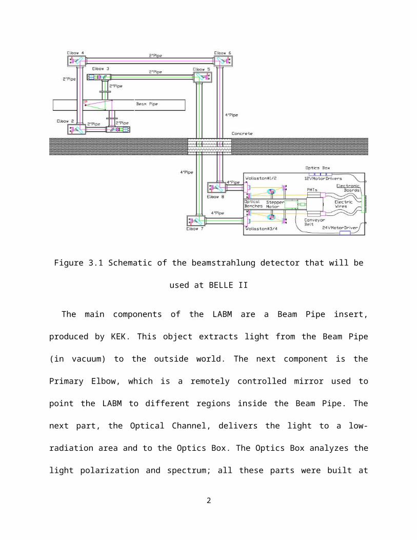
Primary Elbow, which is a remotely controlled mirror used to point the LABM to different
regions inside the Beam Pipe. The next part, the Optical Channel, delivers the light to a low-
radiation area and to the Optics Box. The Optics Box analyzes the light polarization and
spectrum; all these parts were built at Wayne State. The electronics and Data Acquisition are the
responsibility of Sinaloa and Puebla, and of University of Tabuk.
From the primary elbows, light is reflected through an Optical Path shown in Fig. 3.1,
consisting of aluminum tubes with other, larger “manual” elbows. Manual elbows connect two
tubes of 2in and 4in or two 4in tubes. From manual elbows, radiations continue their paths all
the way down through a concrete floor to a room where the optics box resides.
Finally, both beams of light get into the optics box through two windows to meet a Wollaston
prism, which is a polarizer, splitting the light into linearly polarized components. Each polarized
beam is guided onto a ruled diffraction grating. Once polarized light hits the grating, it gets
diffracted and decomposed into its basic wavelengths that can be detected by an array of four
photomultipliers carried by a conveyor belt.
The main role of the conveyor belt is to swap photomultipliers of the same array or of a
different one (detailed in conveyor belt section) for calibration purposes. The optics box also
contains four drivers and their 12Volts power supply for primary elbows stepper motors in
addition to one 24Volt driver for the conveyor belt stepper motor. On the back of the optics box
there is a circuit board with 16 channels to feed all PMTs with high voltage and to get signal
from PMTs through electric wires. From outside, the circuit board has 16 sockets allowing the
user to connect them to 16 digital counters as well as sockets for the motors drivers.
2
3.2 Beam pipe and its components
The Beam Pipe is an 8cm (3.15in) titanium pipe, in which beams circulate in high vacuum.
To get the wavelengths of interest outside, two Beryllium mirrors of 2x2.8mm2 each are placed
away from each other by 6.2cm inside the beam pipe at 45 with respect to the Beam Pipe axis.
The two Beryllium mirrors are small in size to limit RF heating and noise (about 30 Watts at
nominal conditions, the mirrors are water cooled). One ramification is that diffraction effects are
not negligible, but also they act as the first collimator in a double collimator scheme (the
Wollaston prism is the other collimator). On the beam pipe and across from mirrors, there are
two windows of 8mm diameter made of fused silica, through which the reflected radiation
escapes the beam pipe. Each window is mounted on a flange which connects mechanically to the
LABM (Figure 3.2).
Figure 3.1: LABM light extraction element in the Beam Pipe.
3.3 Before Primary Elbow
Since primary elbows support connections between one inch tube and another of different
size mainly 1.5in, they have to have two different aluminum tube adapters. The tube adapters are
3

made out of two identical aluminum pieces of ½in thickness and 2.5x2.5in2 each and can be
easily mounted on the elbow. One of the plates has a circular aperture with a threading diameter
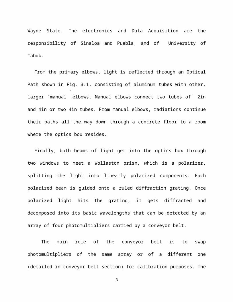
of 1.9393in, and it can be placed on the front of the elbow via screws as shown in Figure 3.3.
Figure 3.3: The Front Adaptor Tube That Connects Primary Elbow to the Beam Pipe adapter.
The other one however has a circular aperture of 1.1811in, and can be placed on the top of
the elbow via screws. It is made in a special way so that it assures the connection between
primary elbow and the aluminum pipe through four set screws on the one side. On the e other
side, the aluminum tube was machined as a solid piece having a plate shape allowing the tube to
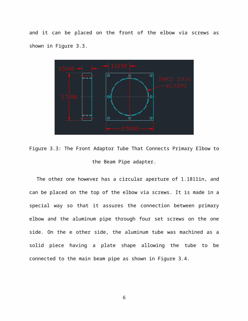
be connected to the main beam pipe as shown in Figure 3.4.
4

Figure 3.4: Primary Elbow Top Adaptor (left), Aluminum Tube (middle)
The finished adapter connecting the primary elbow the beam pipe is picture in Fig. 3.5.
Figure 3.5: The Primary Elbow to Beam Pipe Connector
This adapter tube has a small round window of 0.5in diameter with a holder allowing some
other tools, such as an LED strip or an optical fiber transmitting light to inside the adapter, to be
inserted in for preliminary test as shown in Figure 3.6.
Figure 3.6: L-R Diffuser and LED strip at the Center of Adapter Tube
The diffuser receives light from outside through an optical fiber and diffuses it in all
directions helping in testing elements alignment and PMTs. The LED strip has two LEDs of
5
different colors manly red and green. The latter not purely chromatic, but they have some
bandwidths spread including the intended one that the optics box was originally made for. This
tiny tool has the same role as the diffuser but with more intense light with some specific
wavelengths, and will serve to visually align the Optical Channel.
3.3.1 Primary Elbow: Purpose, Components Design, and Production
The first elbow in the Optical Channel is the Primary Elbow. It is the first element to be
directly connected to the view port on the beam pipe. As stated earlier, this device points the
LABM in different directions. It is located in a high radiation zone that cannot be accessed;
therefore, the mirror inside the elbow has to be remotely controlled. Also, having two identical
view ports, one at the top and one at the bottom of the Beam Pipe, requires two primary elbows
on either side, four in total.
A technical difficulty in building this device was that the mirror control system that was
usually made out of plastic. Angular orientation is driven by two screws pushing and pulling at
opposite points along a diameter of the mirror. The motion of the screws changes the distance
between the two points of contact, which is accommodated by the plastic stretching. Because
plastic cannot be used in this environment, square brass rods were used, which can move along
the axels.
A primary elbow comes out to be a 2.5x2.5in2 black anodized and finished aluminum box of
8in long and ¼in thick to protect all components inside it. It is designed in a compact way so that
it contains small sized components like: an elliptical flat mirror, a 450 mounting adaptor, a mirror
mount and its studs, two square brass rods, two stepper motors and their mount, a circular
window on one of its sides, and finally a back cap as depicted in Figure 3.7.
6
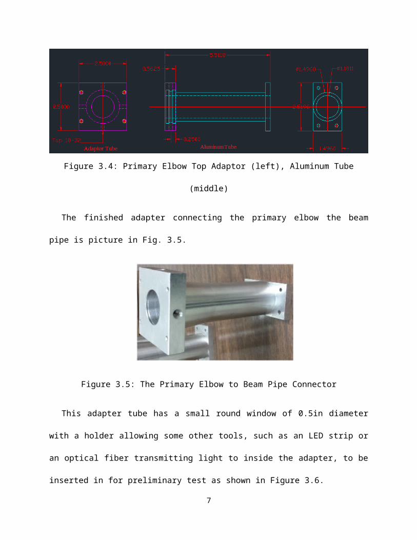
Figure 3.7 Primary elbow design and its constituents.
3.3.2 The Primary Mirror
It is located inside the primary elbow and it is the mirror where the second reflection takes
place after the beryllium mirror inside the Beam Pipe. It is the eye that allows looking at
different radiations areas inside the beam pipe. It is an elliptical flat mirror with 0.875in and
1.237 in minor axis and major axis, respectively. The mirror is oriented at 45 degrees and is
7

coated with a UV-enhanced aluminum layer on its first surface to avoid light attenuation in the
medium of the mirror. The mirror is mounted on a post through a small aluminum disk of 1in in
diameter and ¼ in thickness having a tapped hole at its center and is being glued to it such that
the center of the disk is aligned with that of the reflecting face as depicted in Figure 3.8.
Figure 3.8 Primary mirror elliptical mirror and its mounting disk
The picture also shows that the aluminum disk can be glued to the mirror at an offset about
its thickness from the center of the back elliptical face. The technique of determining where to
glue the disk consisted of laying down the mirror on its back and tracing it on a piece of paper.
Cutting all unnecessary parts helps in folding it symmetrically in both directions. After
determining the center of the ellipsoid, the later was translated by exactly the thickness of the
aluminum disk (¼in) where the center of the disk should be.
3.3.3 The 450 Mounting Adapter:
The primary mirror can be held at 45 degrees from a ½in diameter post by using an easy-to-
use aluminum adapter of 1” offset to hold any component as shown on the right of Figure 3.9. A
socket head cap screw for the ¼in counter bore allows the mounted component to be rotated and
fixed in position in the 45° plane if necessary.
8
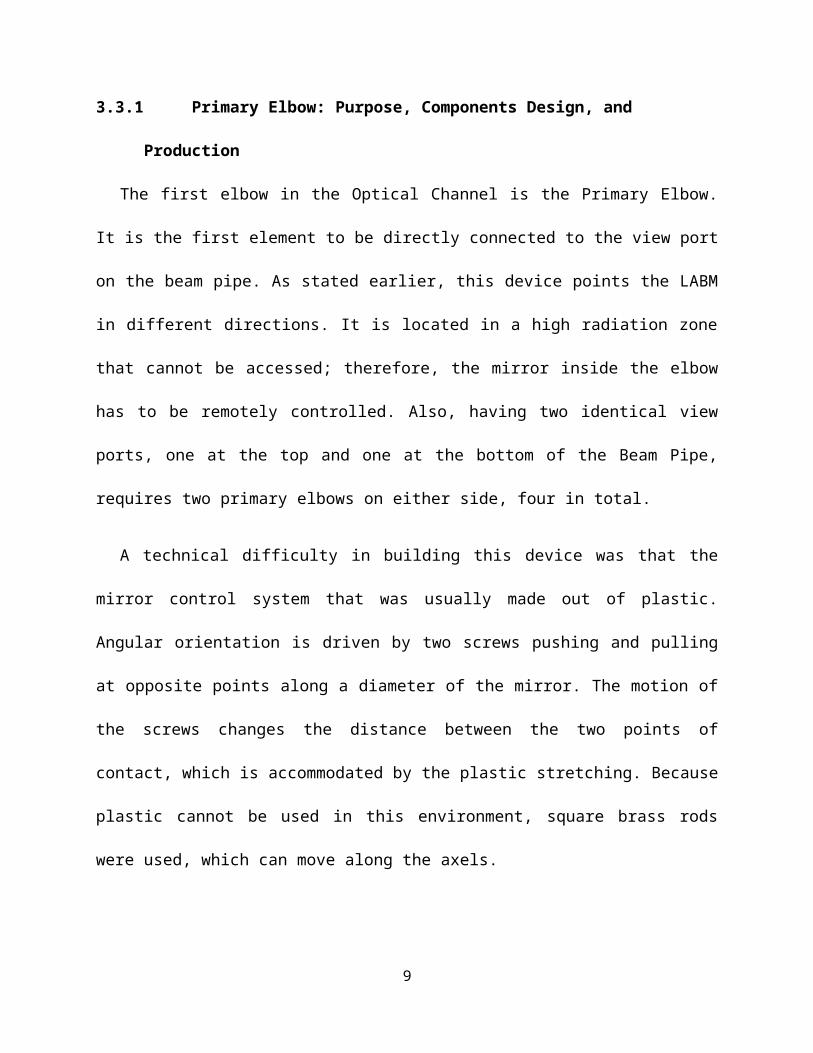
Figure 3.9: 45deg Aluminum Adapter (left) With the Mirror (right)
3.3.4 Mirror Mount and Its Studs:
The mounting adapter can be mounted on a 1in mounting surface having four identical and
tapped holes of a black anodized aluminum miniature straight mirror mount shown in Figure
3.10.
Figure 3.10: Mirror Mount Schematics
The mount includes two fine resolution angular adjustment screws offering the mounting
surface two degrees of freedom at a rate of 0.015in per turn. It also has on its four sides four
tapped holes to allow the mount to be installed inside the elbow. To get the mounting surface
back to its original position, the mount is also provided with a stiff spring joining the installed
9

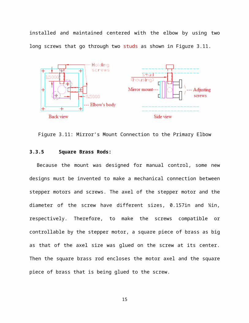
part and the mounting surface. Moreover, the mount can be installed and maintained centered
with the elbow by using two long screws that go through two studs as shown in Figure 3.11.
Figure 3.11: Mirror’s Mount Connection to the Primary Elbow
3.3.5 Square Brass Rods:
Because the mount was designed for manual control, some new designs must be invented to
make a mechanical connection between stepper motors and screws. The axel of the stepper
motor and the diameter of the screw have different sizes, 0.157in and ½in, respectively.
Therefore, to make the screws compatible or controllable by the stepper motor, a square piece of
brass as big as that of the axel size was glued on the screw at its center. Then the square brass rod
encloses the motor axel and the square piece of brass that is being glued to the screw.
When the motor rotates, the brass rod rotates with it turning the screw backward or forward
and, thus, the square piece smoothly slides inward or outward from the brass rod with no friction
as shown in Figure 3.12. Note that intersection length between the cubic piece and the brass rod
is ¼in which is enough for adjusting the mirror. Typically, each turn pushes inward or outward
the mounting surface by 0.015in. Thus, the intersection distance requires 0.25∗10.015
=16turns
which is of course more than enough to center the mirror.
10

Figure 3.12 Square Brass Rods Schematics.
3.3.6 Stepper Motors and Their Mount:
As detailed in the previous paragraph, there are two stepper motors inside each primary
elbow, one per screw. The stepper motors used in primary elbows are all identical, with size
0.8x0.8in2 and axel diameter of 0.157in (Figure 3.13). Each stepper motor is powered by a 2A,
12V driver. The low power is sufficient since the torque needed to rotate a screw is not large.
Figure 3.13: 12V-2A Electric Motor Design.
The motors need a mount to hold them diagonally inside the elbow as shown in Figure 3.13.
The mount of 2x2in2 and ½ in thickness has two square windows of 0.8x0.8in2. Each window is
provided with a tiny screw that can be tightened in to hold the stepper motor in the specified
place. On the outside of the mount, there are two pin holes designed so that two pins can be
easily inserted in and taken out to attach and detach the mount to and from the elbow,
11

respectively. The reason for using pins and not screws is so that the motors do not get jammed
before they operate. Notice that the motors are to be held diagonally because the mount’s screws
are diagonally positioned on the mount as shown before (Figure 3.14).
Figure 3.14 Mounting the Motors on Their Mount inside Primary Elbow.
3.3.7 Circular Window:
This window was designed to allow inspection of the brass rods system during assembly. It
also allows the user to manually control the mirror for a preliminary testing by rotating the
mount screws as shown in Figure 3.15.
Figure 3.15: A Primary Elbow and Its Circular Window to Viewing the Brass Rods
12

3.3.8 Back Plate:
It is an aluminum plate of ¼in thickness and 2.5x2.5in and is used to cover and protect the
elbow from the back. It has a ½in hole allowing the cables of the stepper motors to get outside
the elbow (Figure 3.16).
Figure 3.16 Back Plate That Covers a Primary Elbow and Allows Motors Wiring
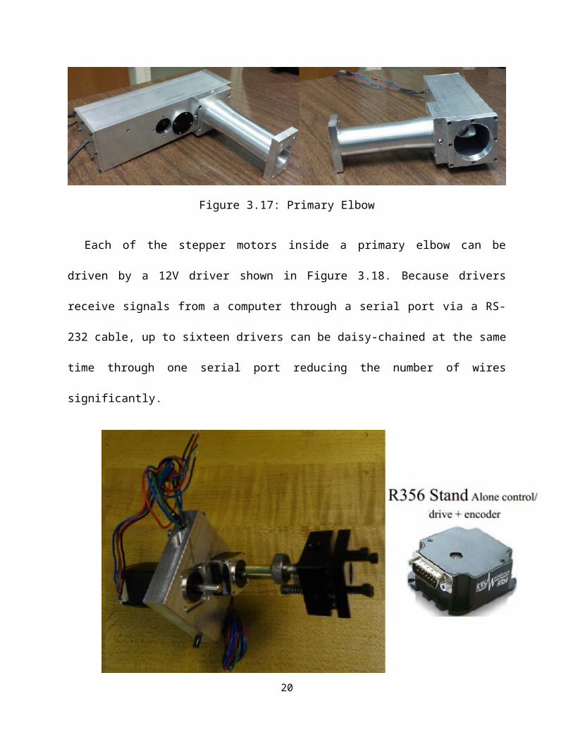
3.3.9 Primary Elbows Production and Hardware:
A finished primary elbow is depicted in the following picture (Figure 3.17).
Figure 3.17: Primary Elbow
Each of the stepper motors inside a primary elbow can be driven by a 12V driver shown in
Figure 3.18. Because drivers receive signals from a computer through a serial port via a RS-232
13

cable, up to sixteen drivers can be daisy-chained at the same time through one serial port
reducing the number of wires significantly.
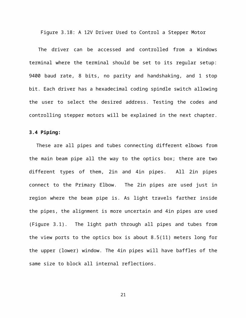
Figure 3.18: A 12V Driver Used to Control a Stepper Motor
The driver can be accessed and controlled from a Windows terminal where the terminal
should be set to its regular setup: 9400 baud rate, 8 bits, no parity and handshaking, and 1 stop
bit. Each driver has a hexadecimal coding spindle switch allowing the user to select the desired
address. Testing the codes and controlling stepper motors will be explained in the next chapter.
3.4 Piping:
These are all pipes and tubes connecting different elbows from the main beam pipe all the
way to the optics box; there are two different types of them, 2in and 4in pipes. All 2in pipes
connect to the Primary Elbow. The 2in pipes are used just in region where the beam pipe is. As
light travels farther inside the pipes, the alignment is more uncertain and 4in pipes are used
14
(Figure 3.1). The light path through all pipes and tubes from the view ports to the optics box is
about 8.5(11) meters long for the upper (lower) window. The 4in pipes will have baffles of the
same size to block all internal reflections.
3.5 Manual Elbows Design, Production, Sandblasting and Anodizing
The manual elbow was designed in a similar way that a primary elbow was, but with several
differences. The mirrors in manual elbows are aligned manually and once, during installation.
Also, they are made out of 0.125in thick aluminum plates that can be joined together via screws
or welded together.
Manual elbows are also designed so that at the front, between the tube adapter and the body,
there is a slit allowing a 1mm diaphragm to fit in. The diaphragm is a thin piece of aluminum
that has a small hole at its center and can be inserted allowing the collimation of light.
Diaphragms of different holes sizes can be used not only to collimate light, but also to adjust
manual mirrors and guide light at the center of the tubes. The first manual elbow in each Optical
Channel adapts to the 2in pipe coming from the Primary Elbow (Figure 3.19), while all other
elbows connect to 4in pipes.
15

Figure 3.19: Back, Front cover, and Two Different Adapter Tubes That Can be Mounted on The
Front of a Manual Elbow.
Manual elbows have bigger mirrors (1.875in minor axis and with mirror mounts of
1.5x1.5in2) that are made in the same way the primary mirrors were. The 1.5x1.5in2 mounts can
be found in many places in the detector including the Optics Box. Such elements must be
mounted on straight mounts as portrayed in Figure 3.20. Only two screws are used to hold the
mount to the elbow’s body to make dismounting the mirror easier especially during first time
system assembly.
16
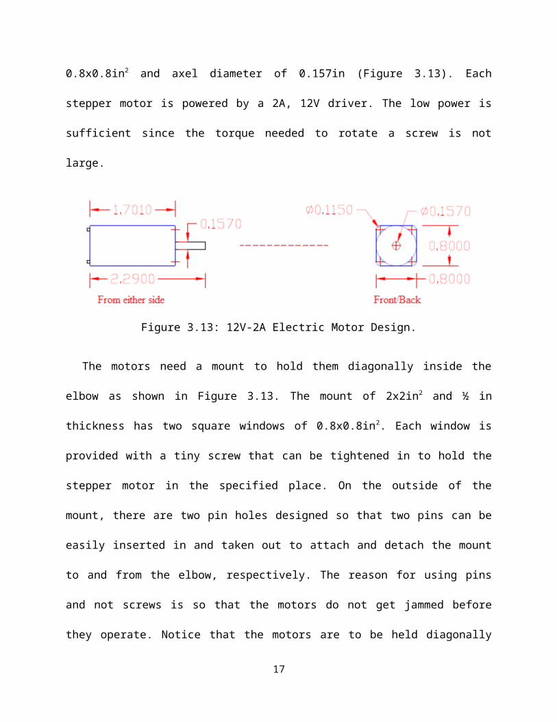
Figure 3.20: An Elliptical Flat Mirror on a Mount inside a Manual Elbow Reflecting Light
Because square pipes of 4x4in2 dimensions are not commercially available, these boxes were
machined and made by welding aluminum pieces together. As a result, the aluminum becomes
not so sticky and dirty and needs to be sandblasted. Thus, all manual elbows were cleaned and
their surfaces were made rough through sandblasting so that they can be easily anodized as
shown in Figure 3.21.
Figure 3.21: A sandblasted primary elbow (left), black anodized finished elbow (right)
17

3.6 Optics Box
The optics box is the core of the LABM, an enclosure of (18x24x44) in3 made out of 0.125in
black anodized aluminum plates. It is located at the end of the Optical Channel. It is designed to
include and protect all other optical elements including Wollaston prisms, reflecting mirrors,
ruled diffraction gratings, prisms-lenses arrays, a conveyor belt, arrays of photomultipliers tubes
(PMTs) and their mu-shields, and two electronic circuit boards, as shown in (Figure 3.1). Two
optics boxes, one for each beam, were produced. Each Optics Box observes both upper and
lower viewports, and is composed of two Optical Benches (Fig. 3.22).
Figure 3.22: The Optics Box and Its Constituents, Top View.
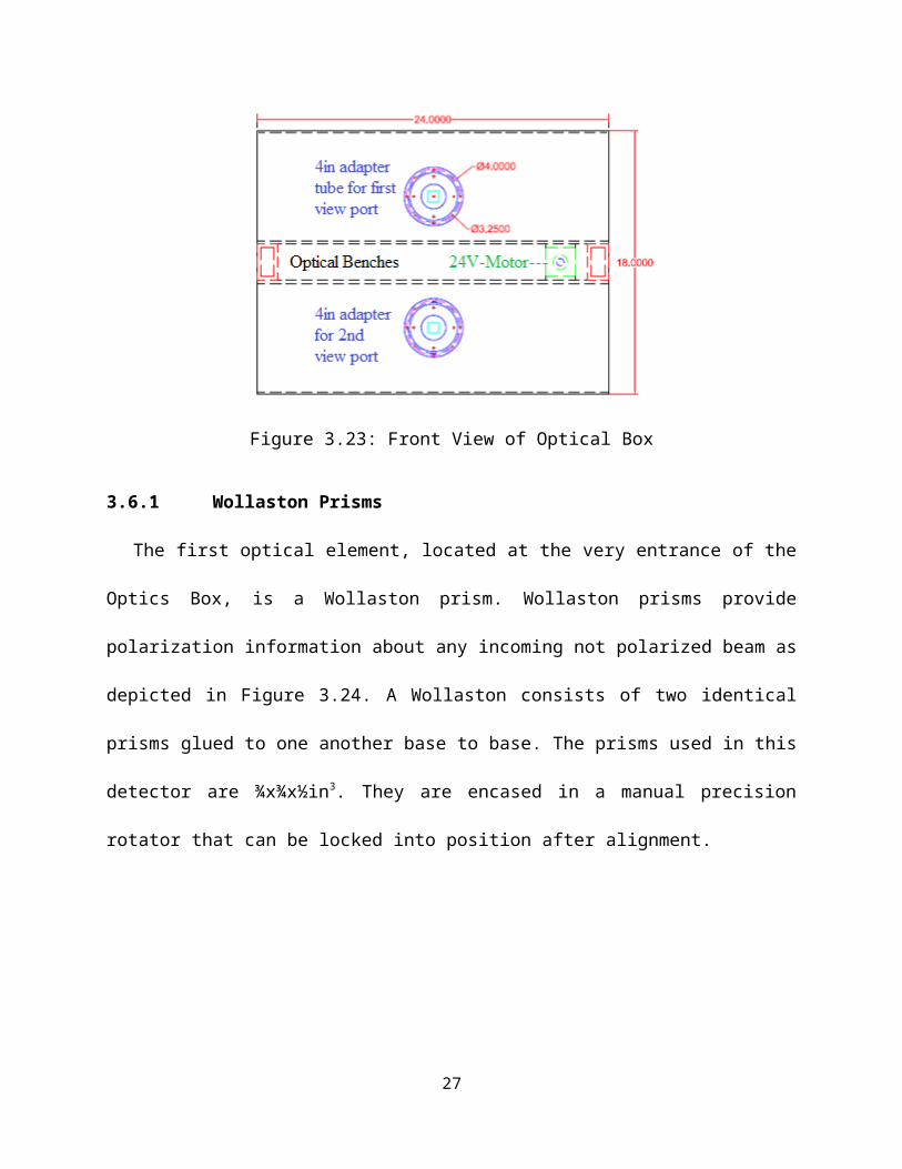
The front view of the Optics Box, showing the two entry windows for the radiation are
shown in Figure 3.23.
18

Figure 3.23: Front View of Optical Box
3.6.1 Wollaston Prisms
The first optical element, located at the very entrance of the Optics Box, is a Wollaston
prism. Wollaston prisms provide polarization information about any incoming not polarized
beam as depicted in Figure 3.24. A Wollaston consists of two identical prisms glued to one
another base to base. The prisms used in this detector are ¾x¾x½in3. They are encased in a
manual precision rotator that can be locked into position after alignment.
Figure 3.24: Wollaston prism splitting one beam into two orthogonally polarized beams.
The Wollaston prism is also called the beam polarizer or splitter because it splits all
incoming non-polarized light into two orthogonally polarized beams, one along the x and another
19
along the y. The polarization parallel to the mid-plane is also called the extraordinary one; the
other one is called the ordinary polarization. Both prisms are mounted on the inside of the front
of the Box (Fig. 3.24).
Figure 3.25: In This Optics Box Side View Wollaston Are Symmetrically Installed on the Front
3.6.2 Ruled Diffraction Gratings
Ruled diffraction gratings are used to decompose a polychromatic beam of light into its
component wavelengths. These gratings are used because they, unlike all other types of gratings,
have the highest intensity in the first order peak. Because the first peak angle depends on
wavelength, optimal efficiency is obtained while spreading the light in angle according the
grating formula:
m=d [sin( )sin (' ) ] (3.1)
Where m is the order of diffraction, is the diffracted wavelength, d is the grating constant
which can be calculated out of the number of groves of the grating, ,∧❑' are the incident and the
diffracted angles, respectively.
20
The investigation of gratings efficiencies were done and reported in Chapter 4.
To choose a diffraction grating that meets all diffraction specifications, the number of
grooves per millimeter and blaze angle which determine the specific wavelength at maximum
efficiencies (400nm to 800nm) according to the formula given in equation (3.1) must be
carefully chosen.
Figure 3.26: Ruled Diffraction Grating Schematic and Angle Definition.
The efficiency of such grating can be determined at the nominal frequencies form the
efficiencies plots shown in Fig. 3.27.
21

Figure 3.27: Efficiency Curves for Ruled Gratings at Various Wavelengths
It is clear that from the above a ruled grating with 600grooves/millimeter would be the best
option due to its maximal efficiency (78%). In regard to the size of the grating, 2x2in2 was
chosen. The beam size (0.8x0.8mm2) could be contained in a smaller grating, but it is desirable
to contain also diffraction fringes. All ruled gratings are mounted on a straight 1.5x1.5in2 manual
mount that is fixed on the Optical Bench via screws as shown in Figure 3.28. The mount position
can be adjusted, facilitating alignment.
22

Figure 3.28: Left: 600 Groves/mm Ruled Diffraction Grating Design, Right: Photo of
gratings/mount assembly.
3.6.3 Optical Benches
Each Optics Box contains two Optical Benches, one per viewport. Each Optical Bench is
divided into two symmetric parts, each analyzing one polarization component. Each part contains
one ruled diffraction gratings, two identical reflecting mirrors, and one set of four different
prism-lens light collectors. The Benches are separated by a distance of 3.9375in allowing the
stepper motor of the conveyor belt to rest in between them. Reflecting Mirrors are used to reflect
light inside the optics box from the Wollaston prisms toward the gratings and to change the
reflection plane from that of the prism to that of the gratings.
Gratings have to be coplanar with photomultipliers carried by the conveyor belt. As the ruled
gratings were chosen to have high efficiency in the frequency domain, also mirrors have to be
chosen the same way. Mirror efficiency measurements are reported in Chapter 4. All mirrors
have the same size of 1.875in and 2.652in minor and major axis, respectively, and the same
coating (UV enhanced aluminum) as the Optical Channel mirrors. For fine adjustment purposes,
they are mounted on 1.5x1.5in2 manually movable mount which is mounted on a post of ½in
diameter being fixed on the optics bench through screws as shown in Figure 3.29.
23

Figure 3.29 Elliptical Mirror Mount.
Positions as well as orientations of mirror are critical and were chosen so that a polarized
beam after two reflections on the mirrors hits the diffraction grating and gets decomposed. The
positions shown on the schematic are not random, but rather were picked by a computer program
estimating all possible positions on a lattice and shown in Figure 3.30.
24
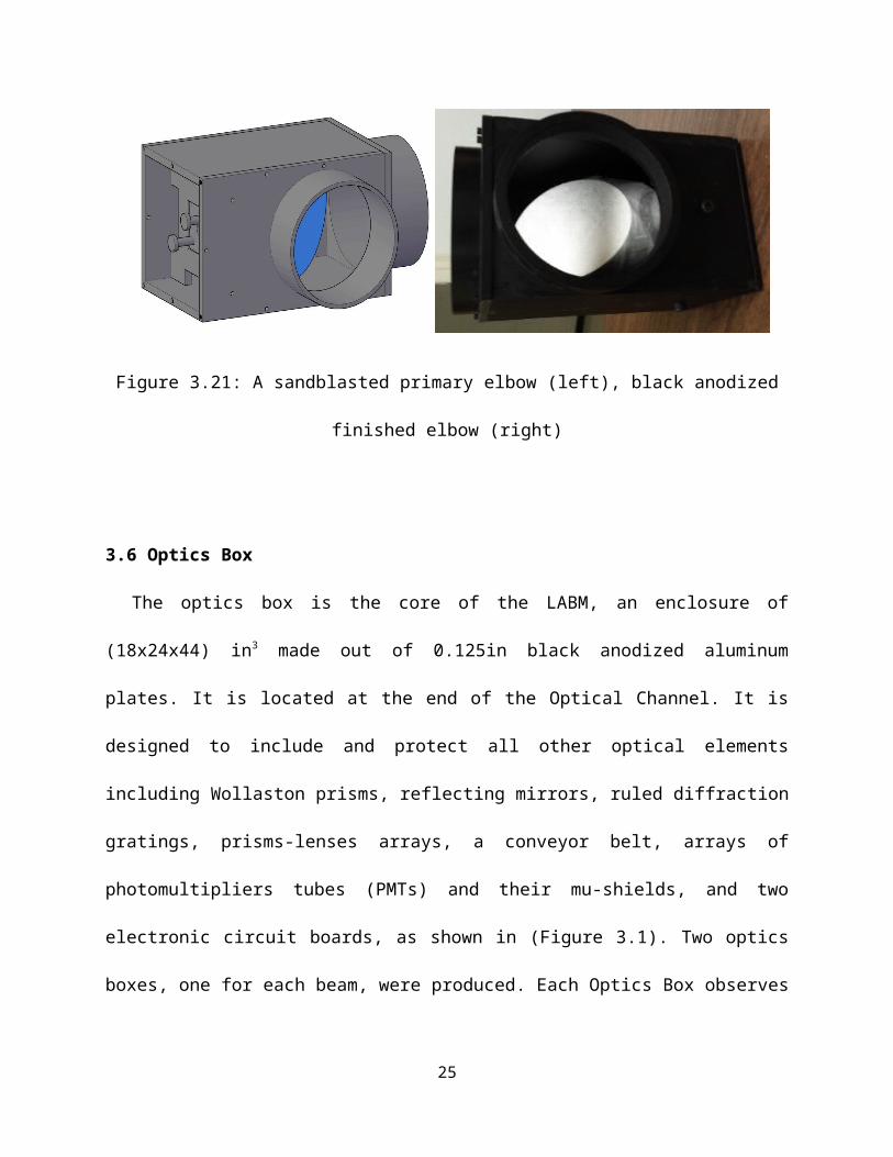
Figure 3.30 Half Optical Bench Schematics.
3.6.4 Light Collectors Motivation, Design, and Failure
The idea behind inventing light collectors was to accumulate all diffracted bandwidths of
light coming from the gratings and have them focused at one point located at the front of
photomultipliers so that they can receive all diffracted wavelengths within the same packet. A
light collector is a 5in long dark object that has a truncated shape at 5deg angle from inside
where four reflecting surfaces are placed. It also has two openings from the front and the back
(Fig 3.31).
Figure 3.31: A light collector from side (left) and front (right) views
The aperture in the front is a square window of 8.1653cm2 through which a bandwidth of
light can get inside the light collector. The back window however is a small square window of
0.16cm2 allowing light, after being collimated, to get out through it after multiple reflections
inside the light collector.
Thus, in front of each grating there was an array of four light collectors to focus light of
different frequency ranges. Table 3.1 shows the optimal frequency range received by each light
collector.
25

Light collectorTop half #1 #2 #3 #4
Frequency range 650nm– 585nm 597nm– 498nm 510nm– 410nm 419nm– 350nmLight collector
Bottom half #5 #6 #7 #8
Frequency range 350nm– 422nm 410nm– 513nm 499nm– 600nm 588nm– 650nmTable 3.1: Eight Light Collectors and Their Corresponding Bandwidths
Light collectors tested poorly. As a result, they were replaced.
3.6.5 Prisms-Lenses system:
Since light collector failed, an optical correction piece was designed using prisms and lenses
glued together. It is obvious that a prism with a proper angle can be used to align the rays parallel
to its base. Then a lens focuses the rays into a small spot on the PMT. Thus, the problem was
with what prism’s angle(s) and what focal distance should be considered. Regarding the focal
distance, the chosen focal length is 15cm since the PMT is 12.5 cm away (incomplete focusing is
obtained, but the PMT longevity will improve when light is somewhat spread out on the
photocathode) as shown in Figure 3.32.
Figure 3.32: Light Path through a Prism-Lens Optical System
The diagram shows the incidence angle (θ) of a beam at the air-prism interface, the refracted
angle () inside the prism of an angle (), () is the refracted angle given by the ruled diffraction
grating with respect to the ground (xxx, the ground? Which ground?) which is well known, and
26
finally the emerging beam being focused at the converging lens focal point located at 15cm away
as mentioned earlier.
The above schematic facilitates using Snell’s law to determine the prism’s angle as follows
with n1 is the index of refraction of air and n2 is that of the prism.
n1 sin (θ )=n2sin () (3.2)
But+α= π2which yields n
1sin (θ )=n2 cos (α ) (3.3)
Since is known and from the geometry of the problem, can be expressed in terms of
and as follows:
π2−+γ+π−α=π (3.4)
thus ,θ=π2+γ – α (3.5)
Equation (3.1) becomes now:
n1 cos ( γ –α )=n2cos (α ) (3.6)
n1 cos ( γ ) cos (α )+n1 sin (γ )sin (α )=n2cos (α ) (3.7)
W here sin (α )=√¿¿ (3.8)
(n¿¿1 cos ( γ )−n2)cos (α )=−n1sin ( γ ) sin (α )¿ (3.9)
27

(n1cos ( γ )−n2 )2Co s2 (α )=n1
2Si n2 (γ )(1−Cos2) (α ) (3.10)
Co s2 (α ) (n12Co s2 (γ )+n2
2−2n1n2 cos (γ )+n12Si n2(γ ))=n1
2Sin2 (γ ) (3.11)
cos (α )=n1Si n ( γ )
√n12+n2
2−2n1n2 cos ( γ ); where n1=1∧n2=1.55 (3.12)
Finally ,α=Co s−1( sin (γ )
√1+1.552−2∗1.55cos (γ ) ) (3.13)
Because each ruled grating is intended to diffract each polarized light into four different
wavelengths (red-green-blue-UV), four different incidences would be obtained and four different
prisms are required and used along with the same converging lens since all PMTs are located in
the same plane.
Solving this formula for different diffraction angles for both polarizations at different
wavelengths, results of typical prisms angles can be tabulated in table 3.2.
Wave length(nm)
Parallel Polarization Perpendicular polarization Average
α(deg)γ (deg) α(deg) γ (deg) α(deg)
350 10.3 72.4 7.9 76.2 73.4405 6 79.3 6.9 77.9 75431 4 82.7 -0.4 89.3 86.65500 -0.8 88.6 -2.2 86 87.3532 -3.3 84 -7.8 76.4 79.55635 -10.5 72.1 -9.7 73.3 76.3650 -11.6 70.6 -14.1 67.2 69.8
Table 3.2: Various Prisms Angles vs. Different Angles of Incidence (xxx, why are the angles so
different for par and perp?).
28

To replace the useless light collectors, two sets of four different prism-lens optical elements
of angles 72, 75, 82, and 90 degrees can be determined from the above table satisfying the
requirements. As explained previously, these prisms allow light to internally strike the lens
normally so that all rays converge towards the focal point of the likely lens and eventually to the
corresponding PMT as shown in Figure 3.32.
The dashed lines of different colors represent the ideal incident diffracted rays off the ruled
diffraction gratings on both sides of the optical bench. Notice the symmetric structure of both
sides’ components which compatible with that of the PMT’s on the conveyor belt as detailed in
the next section.
29

Figure 3.32: Array of 8 Prisms-Lenses Collection Mounted in Their Frames and Facing PMTs
3.6.6 Conveyor belt and its stepper motor
The purpose of the conveyor belt is to allow online swapping of the PMTs, to obtain precise
relative efficiency measurements. The stepper motor is a 24V-2A stepper motor. The conveyor
belt has 5in width. This conveyor belt dimensions were chosen that way because it needs to carry
sixteen photomultipliers, each observing a viewport, as depicted in Figure 3.33.
30

Figure 3.33: Front and Side Views of Conveyor Belt Carrying 16 PMTs
The eight photomultipliers on top in Fig. 3.33 observe the top Optical Bench, four each for
the x and y-polarization (A for x-polarization and C for y of the top view port). Likewise, the set
of eight at the bottom is for the other Optical Bench (B for x-polarization and D for y of the
second view port). The conveyor belt, when rotated by the stepper motor which is remotely
controlled via computer, moves all PMTs around giving all possible measurements of x and y
polarizations of the same beam and/or different beams, yielding a matrix of measurements that
can be used to measure relative efficiencies. All PMTs can be calibrated and characterized inside
the Box.
This conveyor belt is controlled by a PC through a serial port. The controller has a
memory that saves programs in it, and it can be accessed from a Windows terminal. To view the
programs saved into the memory or to run a control program, a protocol must be followed as it
was tested (explained in Chapter IV).
3.6.7 Photomultipliers Definition and Applications
A PMT is a glass tube. On the face receiving the light, it has a very thin (few atoms) cesium
compound layer coated inside it; as it gets illuminated by an incident photon, it emits one
electron via photoelectric effect, with probability of 20% or lower (3e-), towards the facing
anode or dynode as shown in Figure 3.34. The inside of the PMT is held at vacuum.
31

Figure 3.34: Photomultiplier and Photoelectric Effect Principle
The first dynode, struck by an electron with kinetic energy of order 100 eV, will emit on
average about 3 electrons. The phenomenon continues from one dynode to the next, which
results in a significant electric current on the last anode in the order of milliamperes (mA). Since
the electron trajectories inside the PMT are sensitive to magnetic fields, the photomultiplier
should be covered with a high permeability material. This is called -shielding. Because the
current or signal obtained by a PMT is still difficult to detect, it could be amplified before
discrimination and counting.
3.6.8 Electronics and Back plate
This piece of hardware has two roles: one to cover the box from the back, and two to support
the electronic board that is consisted of amplifiers, discriminators, high voltage sockets, and
output terminals for counting. The electronics is being developed in Mexico. Here only the back
panel, which brings HV cables in and signal cables out, is discussed. The back-panel also feeds
through the stepper motor cable. The back panel is shown in Fig. 3.35.
32
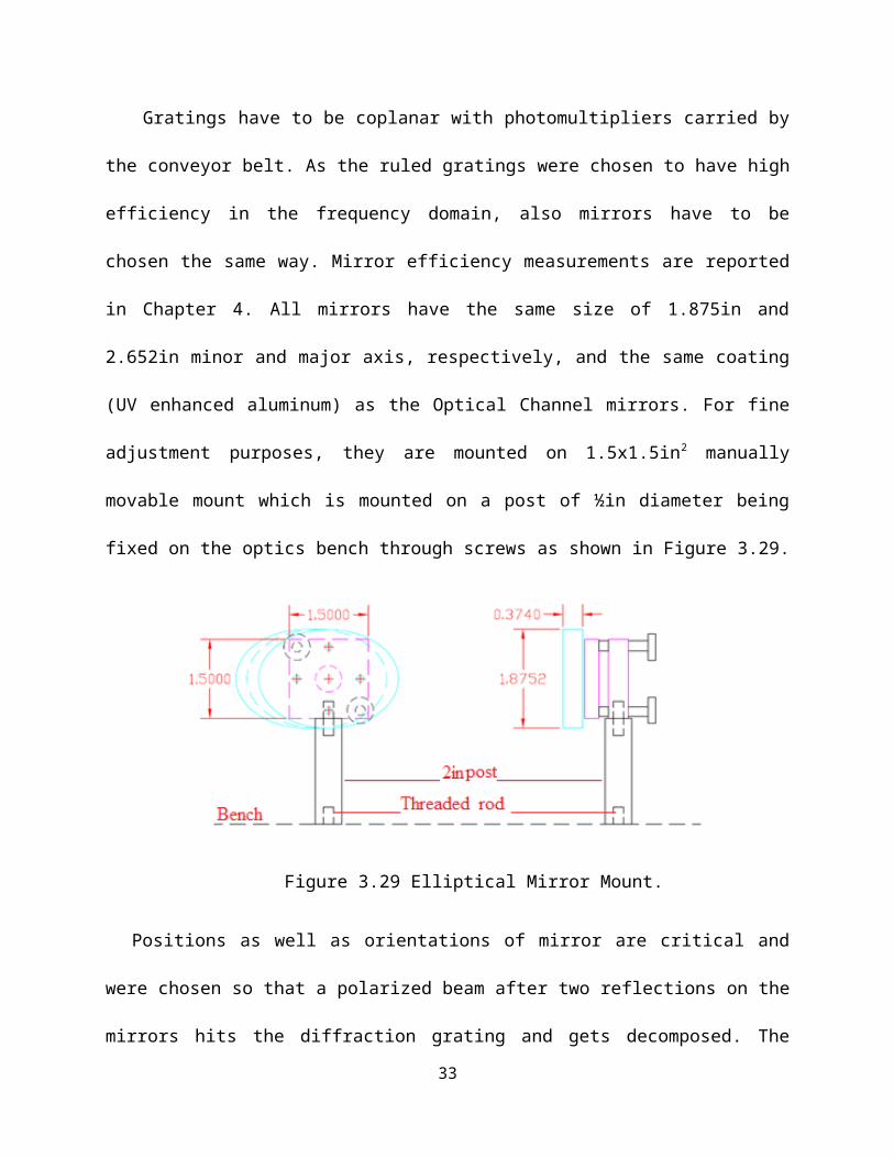
Figure 3.35 Design of the back panel.
This produced back panel shown in Fig. 3.36 which will be embedding all electronics from
Mexico will be replacing the old electronics that will be discussed in the next section.
Figure 3.36: High Voltage Sockets (Left) and Rails (Right) on the Back Plate
33

3.7 The Electronic Setup
The electronic setup consists of a high voltage power supply to power up 8 PMTs at a time,
8-channel amplifiers of gain 10 each, discriminators where signals selections take place, and
digital readouts to visualize the number of photon counts.
The crate and its component are shown in Figure 3.36. This setup played a big role in this
research because it was used many times in performing all tests including PMTs’ calibrations
and characterizations. PMTs Characterization means determination of the dark noise or the
background signal of each photomultiplier when there is no light inside the box.
Figure 3.36 Electronic setup
Fortunately, the box was built to be dark enough and the background signal was measured by
each PMT. However, calibration means determination of the PMT spectral response, plateau and
34

operational voltage well as the threshold voltage of each PMT. Spectral response means studying
how each photomultiplier acts at different frequencies of light.
3.8 Anodized Aluminum Box
Finally, all produced components and elements can be mounted inside the big optics box and
would be enclosed and ready for use after testing as it will be explained in the next chapter. The
real and final detector then looks like the one depicted in the below picture (Figure 3.37).
Figure 3.37 Anodized Assembled Optics Box Containing All Optical Components
35