alaska hydro corporation 2633 carnation street …€¦ · · 2018-01-08alaska hydro corporation...
TRANSCRIPT
ALASKA HYDRO CORPORATION 2633 Carnation Street
North Vancouver, BC V7H 1H6
TSX Venture Exchange: AKH
September 27, 2017 British Columbia Utilities Commission Suite 410, 900 Howe Street Vancouver, BC Canada V6Z 2N3 Attention: The Secretary
Dear Members of the Commission,
I would like to respond to the Panels comment in Sec 1.1.9, Page 28, last line…." The Panel finds that while this project may show promise, it is at an early stage of pre-development. Accordingly we are reluctant to draw any conclusions from the material presented by Alaska Hydro".
I would like to introduce for your consideration BC Hydro's own report….’The Iskut Canyon & More Creek Projects Preliminary Design Study Phase 1 Interim Report No. H1674’. Included is a Synopsis of this report (attached) taken from pages xi to xiii of the BC Hydro report. This report is supported by a number of technical reports. Section 1.3 of this report details work completed and is reported to constitute approximately one half of the work required to complete phase 1 of the preliminary design of the project (attached pages 1-3 and 1-4 of the BC Hydro report).
Since the BC Hydro report was produced Alaska Hydro Corporation has prepared a prefeasibility study on a smaller project dated June, 2015 and entitled ‘More Creek Hydroelectric Project Prefeasibility Study’ (attached). The Company relied heavily on BC Hydro's report. The Company has advanced the engineering design of the Dam with a Report prepared by Golder Associates dated 6 September 2017 entitled 'Prefeasibility Study of the Dam for More Creek Hydroelectric Project’. This report confirms BC Hydro's selection of dam type and location (attached). The Company has determined that the project is economic and will cost less then half the construction cost of Site C. This is based on BC Hydro's own estimates of the More Creek project and Alaska Hydro's estimate for a smaller project. The information at this juncture is sufficiently robust that it can be reliably compared to other alternative energy projects and, given the materiality of this alternative to Site C, the More Creek Project should be given more attention and an adequate weight. I would suggest the More Creek project is not in an early stage of pre-development but in fact is in the final phase of pre-development based on the work completed to date.
Regards
Cliff Grandison President & CEO Alaska Hydro Corporation
11-3

, . .:-\
{ I,
AR150
SYNOPSIS
The proposed Iskut Canyon and More Creek projects would provide 980 MW
of the 2900 MW Stikine-Iskut Development . The Iskut Canyon Project, located on the Iskut River just downstream of the Forrest Kerr Creek
confluence, would deve 1 op an average gross head of about 192 m. The More Creek Project would be located on More Creek, approximately 1.5 ' km
upstream of the confluence with the Iskut River. would develop an average gross head of 141 m.
. half of the Forrest Kerr Creek into More Creek by
dam would form. part of the More Creek Project .
A dam at this location Diversion of the upper a 50 m high embankment
Preliminary design studies for the Iskut Canyon and More Creek projects began in 1981. Studies continued until mid 1983, when lower forecasts of electrical energy demand indicated that the preliminary design
studies co~ld be deferred for several years. Because the studies were to be deferred for an unspecified time period, it was decided to prepare
this report to pro vi de an assessment of the generation engineering studies and to fully document all generation engineering work carried
out to date. An assessment of the overall Stikine-Iskut Development is ·
given in a separate report.
Two summer seasons of preliminary design site exploration were carried out in 1981 and 1982 which included drilling, permeability testing ,
mapping and geophysical surveys. In 1983, because of the decision to
defer the studies, the field program was limited to completing the 1982
program of permeability testing and geological mapping.
Investigations have shown that the foundations at both project sites are generally suitable for the proposed structures and that construction
materials are available from required excavations and borrow pits. However, certain critical work needs to be completed, such as that
- xi - H 1674

(
AR150
required to make a seismic and volcanic assessment of the project areas
and to complete the assessment of the permeability of the lava flats at the Iskut Canyon site.
The lengths of record for the seismic, hydrometric and climatological
data are considered short for the purposes of completing the preliminary design studies. The Advisory Board concurred and recommended cont i nuation of data collection. A monitoring program should be put in place to obtain at least 10 years of seismic data, and 10 years of concurrent
hydrometric and climatological data prior to completing preliminary design phase 1 studies.
Sufficient information has been gathered to assess the general behaviour of the proposed reservoir s 1 opes during operation of the projects.
However, more information is required in some areas, particularly in the More Creek reservoir, before the risk of a major slope failure occurring can be a·ssessed.
A number of alternative project arrangements have been studied for each project site, but a number of questions remain to be resolved before one
of these can be selected for each site. For each project site a featured arrangement has been shown, which is considered to be the most
promising at this time. It is realized, however, that once the site investigations and office studies are completed, an alternative layout could possibly be identified as more suitable and become the selected
arrangement. A number of recommendations concerning future studies are made and critical studies which should be carried out on resumption of
studies are identified.
The featured arrangement for the Iskut Canyon Project comprises a 180 m
high embankment darn with impervious core in the canyon, a 56-m high concrete-faced rockfill dam located on the left bank lava flats and an
underground powerhouse 1 ocated about 1. 5 km downstream of the canyon
dam. The powerhouse waul d be 1 ocated underground in the 1 eft bank and
- xi i - H 1674

AR150
would contain three 270 MW units. A low level outlet, an intermediate level outlet, an auxiliary spillway and a fuse plug spillway would be provided for control of the reservoir.
The featured layout for the More Creek Project consists ·of a 145 m high
arch dam with five jet flow gate outlets and an underground powerhouse located in the left bank. The powerhouse would contain two 85 MW units.
The five jet flow gates would provide for all the required spillway releases.
The following tabulation summarizes the flows, capacity, energy and cost data for the featured project arrangement for both projects.
Average River Flow (1940-1981) Maximum Normal Reservoir Level Maximum Reservoir Drawdown Installed Generating Capacity Maximum Net Head Number of Units Average Annual Energy Construction Cost ($ Million)*2 Construction Cost of Capacity Combined Cost of Capacity Construction Cost of Average Energy Combined Cost of Average Energy
Iskut Canyon More Creek
260 m3/s 70 m3/s* 1
347 m 535 m 35 m 42 m
810 MW 170 MW 193.9 m 150.4 m
3 2 · 4iO MW 80 MW 1070 380
$1320/kW $2240/kW $1480/kW
$2610/av kW $4750/av kW $2960/av kW
Note: *1 Includes flow from Forrest Kerr Diversion.
*2 October 1983 price levels. Interest during construction and corporate overhead costs are not included .
The estimated total construction times from award of first contract to first in-service date are estimated to be 6 3/4 years for the Iskut Canyon project and 5 3/4 years for the More Creek Project. The duration of construction for each project has been increased 1 year from that reported in the Fe as i bil i ty Report. The increase for the Iskut Canyon Project was due to a reassessment of the time required to build the main
dam in the narrow canyon. The increase for More Creek was due to the assumption . that the dam would be completed prior to impounding the reservoir. The feasibility studies assumed that the reservoir would be
filled part way prior to completing the construction of the arch dam.
- xiii - H 1674

(
(
problems, particularly those involving safety and high cost, are
investigated. An assessment is made regarding safety of the proposed
project structures, the impact of the deve 1 opment on the environment,
the project operation and power production, the estimated project costs
and the schedule.
As a result of the lower load forecasts the assignment was revised in
June 1983 to suspend further deve 1 opment studies and to provide for
documentation of the investigations and studies already carried out.
1.3 WORK ~OMPLETED
AR150
The investigations and studies undertaken to the end of 1983 constituted
approximately half of the work required to comp 1 ete phase 1 of the
preliminary design. The principal work items completed, which are
described in detail within the body of this report, are as follows:
1. Preparation of topographic maps for the project areas.
2. Site foundations investigations, including exploratory drilling,
permeability testing, geophysical exploration, geological mapping
and laboratory testing .
3. Construction materials investigations, including sampling and
laboratory testing.
4. Reservoir shoreline stability studies.
5. Studies to determine the probable maximum flood, flood frequency,
sedimentation and ice formation .
. 6. Power studies to determine energy potential and to optimize major
project parameters.
1 - 3 H 1674

AR150
7. Project arrangement studies of three alternative dam types for both
projects.
8. Studies to route floods through the proposed reservoirs and to
determine reservoir filling periods.
9. Studies to determine construction facilities and project access.
10. Preparation of cost estimates and schedules for each project
arrangement.
11. Documentation of all project studies for future use.
1 - 4 H 1674

Alaska Hydro Corporation
More Creek Hydroelectric Project
Prefeasibility Study
June 2015
E6348
SIGMA ENGINEERING LTD 1444 Alberni Street, 4th Floor, Vancouver, BC, Canada V6G 2Z4 Phone: (604) 688-8271 Fax: (604) 688-1286

More Creek Hydroelectric Project Prefeasibility Study
Sigma Engineering Ltd. ii May 2015
TABLE OF CONTENTS Table of Contents .............................................................................................................. ii List of Tables ..................................................................................................................... ii List of Figures.................................................................................................................... ii Preface .............................................................................................................................. 3 1. Background ................................................................................................................ 3 2. Hydrology ................................................................................................................... 3 3. Generation and Revenue Estimates .......................................................................... 4 4. Construction Cost Estimate ....................................................................................... 6 5. Financial Analysis ...................................................................................................... 8
LIST OF TABLES Table 1 Mean Monthly and Annual Flows at proposed intake Table 2 Monthly targets for design flow Table 3 Generation estimates (GWh) Table 4 Prefeasibility Cost Estimate
LIST OF FIGURES Figure 1 Location Plan Figure 2 Project Layout Figure 3
More Creek Storage Curve
APPENDIX A Financial Analysis

More Creek Hydroelectric Project Prefeasibility Study
Sigma Engineering Ltd. 3 June 2015
PREFACE This study has been prepared exclusively for Alaska Hydro Corporation for the purposes of assessing the proposed More Creek hydroelectric project. No third party is entitled to rely on this analysis without the express written permission of Sigma Engineering Ltd and Alaska Hydro Corporation.
1. BACKGROUND Alaska Hydro Corp. (AHC) is interested in a prefeasibility study for the proposed More Creek hydroelectric project, located approximately 10 km northwest from Bob Quinn Lake in the Skeena region of British Columbia.
The present study will use the existing project layout and characteristics, as described in the submitted Water License Application. The 75 MW project consists of access roads, an intake, a dam, a tunnel and penstock, powerhouse and generating equipment, transmission line and interconnection to the Bob Quinn BC Hydro substation (see Figures 1 and 2).
Below we describe our methodology and assumptions in developing a model to estimate the projected revenues (hydrology and generation model), and our considerations for developing prefeasibility cost estimates for the project.
2. HYDROLOGY The hydrology is based on flow data from the Water Survey Canada (WSC) streamflow gauge ‘08CG005 – More Creek near the mouth’. The gauge was located near the proposed intake site and was active from 1972 to 1995 and has a set of 19 complete years of daily flow data available. The drainage area of WSC 08CG005 is 844 km², which is the same as the drainage at the intake of the proposed project. Thus the flow data from the WSC gauge are used without any adjustments as the basis of the hydrology at the site.
The mean monthly and annual flows at the site are shown in Table 1 below:
Table 1. Mean Monthly and Annual Flows at proposed intake

More Creek Hydroelectric Project Prefeasibility Study
Sigma Engineering Ltd. 4 June 2015
3. GENERATION AND REVENUE ESTIMATES A spreadsheet model is used to calculate the monthly and annual generation at the site. The model uses 19 complete years of daily flows as the basis of the calculations.
Assumptions The basic assumptions used in the model are:
Design flow 80 m³/s
Dam crest elevation 498 m Minimum lake level 468 m Mean tailwater level 380 m Gross head 88 - 118 m
Instream flow release 2.476 m³/s (5% of mean annual flow) Minimum turbine flow 20 m³/s
Installed Capacity 75.2 MW Generating equipment efficiency 86.45% Friction head loss (waterway) 6%
The following lake storage curve is used (Figure 3). The curve was developed based on available 1:20,000 mapping.
Figure 3. More Creek Reservoir Storage Curve
The 30 m of available storage is equivalent to approximately 90 days of storage at the design flow. The simple operation of the plant would dictate that excess water is stored during the summer months and used in the fall and winter months.

More Creek Hydroelectric Project Prefeasibility Study
Sigma Engineering Ltd. 5 June 2015
However, this operation assumes that the electricity price is the same throughout the year. Since at this stage, the electricity pricing scheme is not known, the model used the current BC Standing Offer Program (SOP) monthly delivery time adjustments to vary the electricity price through the year.
The model used monthly targets for the design flow to simulate the operation of the plant and maximize the average annual generation and revenue. Our preliminary analysis determined that the following monthly targets for the design flow resulted in the maximum generation at the plant:
Table 2. Monthly targets for turbine flow
The resulting monthly and annual generation estimates are shown in Table 3 below:
Table 3. Generation estimates (GWh)
If an electricity price of $100/MWh is assumed the same throughout the year, then the average annual revenue would be $34.5 million. Note the lowest and highest annual revenue are $29.5 and $44.0 million respectively.
Applying the current BC Hydro monthly delivery adjustment factors, the average annual revenue would be about $34.8 million, ranging from $29.8 to $44.4 million.
Note that if the electricity price variance through the year is different from that of the current SOP, the monthly target for the turbine flow may differ from the ones shown above. Also, the impact of any monthly variation of electricity prices may vary depending on price variance and plant operation.

More Creek Hydroelectric Project Prefeasibility Study
Sigma Engineering Ltd. 6 June 2015
Impact on Forest Kerr hydro project The operation of the More Creek hydro project would potentially increase the generation of the existing Forrest Kerr project, located downstream from the More Creek powerhouse. The storage of water during the summer months, when Forrest Kerr would typically be spilling water, and the subsequent release of the stored water over the winter months would increase the Forrest Kerr generation potential.
The operational details of the Forrest Kerr project are not available to us. A high level estimate of the potential additional generation at Forrest Kerr is based on converting the additional flow (m³/s) to power (MW) using a factor of 0.80. The additional average annual generation at the Forrest Kerr project, using the above assumptions, is estimated at about 149 GWh.
4. CONSTRUCTION COST ESTIMATE A prefeasibility cost estimate for the project has been developed based on the existing conceptual level design and layout. Any consideration of additional design options or optimizations is outside the scope of this study.
Sigma has attempted to indicate potential areas for future consideration. The geotechnical characteristics in the area of the proposed dam will have a considerable impact on the selected type of dam and the associated cost. The access to the project area is from an existing road and bridges over Iskut River which is shown on online mapping. It appears that the road may be subject to seasonal flooding. For the purposes of this study, it is assumed that the road will be accessible and that technical issues will be addressed in future studies.
The attached Table 4 shows the prefeasibility construction cost estimate for the project. Table 4. Prefeasibility Cost Estimate

More Creek Hydroelectric Project Prefeasibility Study
Sigma Engineering Ltd. 7 June 2015
General Comments A. Access Roads
Pricing based on recent project built on Vancouver Island.
B. Intake Structure
Reinforced concrete pricing based on pricing for recent projects. Pricing for Roller Compacted Concrete (RCC) was developed with input from contractors with RCC experience.
An earthfill dam or arch type dam may be an option in the confined portions of the canyon.
Pricing for trashracks, intake gate is based on price per square foot from a recent project.
Radial gate pricing based on square foot pricing of smaller gates.
Power supply to intake area assumed typical 25 kV line costs.
C. Tunneling
The 1,000m long penstock tunnel is 5.5m x 5.5m. The 200m long diversion tunnel is 12m x 12m. Cost for the two tunnels is based on a cost estimate provided to Sigma by CanMine Contracting LP.
D. Powerhouse Structural
Cost estimates are prorated from actual costs for small plants, with an adjustment for economy of scale.
E. Powerhouse Generation Equipment
Cost estimate for generating equipment is based on quote from Chongqing Yunhe Hydropower Inc. plus an allowance for $1 million for trifurcation. The turbine quote was for 3 horizontal Francis units with generators and a bypass valve to meet environmental criteria.
Balance of plant cost estimate is based on prorated cost of smaller plants discounted by 25% for economy of scale. Balance of plant includes all electrical items not in Turbine-Generator package. Includes controls, switchgear, transformers, grounding, plant wiring, etc.
F. Transmission Line
Cost estimate for 3 phase 287 kV line to Bob Quinn is based on unit cost of 69kV line for a recent project, increased for voltage.
An allowance is made for the BCH interconnection price which is very difficult to estimate at this stage.

More Creek Hydroelectric Project Prefeasibility Study
Sigma Engineering Ltd. 8 June 2015
G. Work Camp
Pricing per man-day is based on quote from full service camp provider. Estimate of number of man-days is based on the total project construction cost.
Limitations The estimates presented in Table 4 do not include or allow costs for the following:
o Possible fish screens
o Trashrack automatic racking
o A seepage blanket, or grouting, to prevent leakage around the dam
o Plunge pool construction for spillway (may be required depending on site conditions)
o Wildlife and First Nations compensation
o Clearing of reservoir. It is assumed to be zero (trees sold for value equal to clearing cost)
o Potential relocation of a Nova Gold (Galore Creek) road that may be flooded. This road may not be needed beyond the More Creek dam location, unless the mine project is restarted.
5. FINANCIAL ANALYSIS The financial analysis of the project is based on a 40-year period. Sigma used a spreadsheet financial analysis model that has been developed and used for hydroelectric projects in BC. The analysis takes into account the estimated construction costs and escalating annual operating costs (O&M, administration, property/liability insurance, water rent, property and school taxes).
The analysis does not include any land acquisition and permitting costs, royalty payments or wheeling fees. The analysis indicates the expected net present value (NPV) and internal rate of return (IRR) for the project (see Appendix A).
Assumptions o The annual gross generation from Table 3 is used.
o The construction cost from the previous sections is used.
o The capital cost of the project includes cost estimates for Project Management, Engineering and Finance costs, expressed as a percentage of the construction cost. The estimates are based on typical costs for hydroelectric project in BC. The capital cost also includes an inflation adjustment from 2015 to 2017.
o The annual operating costs include the following, all adjusted annually for inflation:
Administration and Operation and Maintenance Cost as 1% of the Capital Cost
Insurance cost. Based on typical industry rates, which need to be confirmed by insurance professionals.
Water Rent based on 2014 rates.

More Creek Hydroelectric Project Prefeasibility Study
Sigma Engineering Ltd. 9 June 2015
Property and School Taxes. Typical BC rates are used which will need to be confirmed at a later stage.
o The analysis assumes 20% equity, 25 year amortization, an effective interest rate of 5.5% and an electricity price of $100/MWh.

ALASKA HYDRO CORPORATIONMORE CREEK HYDROELECTRIC PROJECT
LOCATION PLAN & WATERSHED
DATE
SIGMA ENGINEERING LTD
JUN 15
PROJ.
E6348
DWN.
ND/DGC
DWG.
FIGURE 1
0
1. BASE MAP FROM NTS 1048 ISKUT RIVER & 1 04G TELEGRAPH CREEK, ORIGINAL SCALE 1:250,000
2. COORDINATE SYSTEM UTM ZONE 9, NAO 83
5 10 15 20km
SCALE

ALASKA HYDRO CORPORATIONMORE CREEK HYDROELECTRIC PROJECT
GENERAL ARRANGEMENT
DATE
SIGMA ENGINEERING LTD
AUG 14
PROJ.
E6348
DWN.
DGC
DWG.
FIGURE 2
\ <D
\ ~
I I
1. CONTOURS FROM BMGS, ILMB, CANADIAN DIGITAL ELEVATION DATA, GEOBASE 1.0; SOURCE DATA = BC- TRIM; SOURCE SCALE 1: 20,000; CONTOUR INTERVAL SHOWN = 1Om
2. WATERCOURSES AND LAKES FROM BMGS, ILMB, CANADIAN HYDRO NETWORK 1.0-CL4-NC4; SOURCE DATA = BC- TRIM· SOURCE SCALE = 1:20,000 .
3. COORDINATE SYSTEM = UTM ZONE 9, NAO 83
oc===~~~10i0==~==~20~0==~==~3~00==~====3400m
SCALE

More Creek Hydroelectric Project DRAFT Prefeasibility Study
Sigma Engineering Ltd. 10 June 2015
APPENDIX A Financial Analysis

Last Revised 06-Jul-15 PRELIMINARY FINANCIAL ANALYSIS FOR POWER SALESSpreadsheet by: CL
BASIC PARAMETERSTable 1
POWER PRODUCTION DETAILS ANNUAL OPERATING COSTS FINANCING DETAILS
Admin., O&M as a Percent of Capital Cost Total Capital Cost 296,534,187Hydro Power Plant Rated Capa 75,255 kW Daily Admin., Operation & Maintenance incl Equity Input 20.0%Max Power Supplied to BCH 75,255 kW Annual Overhaul & Equip. Repair 1.00% Equity Amount 59,306,837Power Plant Load Factor 50.3% First Year Total O & M Cost (incl. admin) $2,965,342Avg Annual Generation 37,822 kW Finance Amount 237,227,349Net Annual Power Sales 331.320 GWh/yr O & M Inflation Rate 2.3%
Amortization Period 25 YearsGross Generation 345.000 GWh/yr Reference Interest Rate 3.50% Prime Rate
Daily vs Real time adjustment 0.0% Insurance Interest Rate over Refer. 2.00%Station Service 200 kW Property Value for Insurance Purposes Effective Interest Rate 5.50%
Transformer/powerline losses 2.5% 100% of Capital Cost $296,534,187 Annual Payment $17,685,145Outages (sched., unsch.) 1.0% Property Insurance 1.50 $/1000
General Liability $10,000,000 Liability Insurance 6.00 $/1000
Access Roads 682,500 First Year Insurance $504,801 TAXATION DETAILSIntake structure (incl.RCC) 111,845,000 Insurance Inflation Rate 2.3%Tunneling 19,300,000 Corporate Taxation Rate 42.8%Powerhouse 18,500,000 Water RentGeneration Equipment 27,274,000 Water Tax on Engy Produced (<160GWh) 1.288 $/MWh Percent of Capital Cost 90.0%
Water Tax on Engy Produced (>160GWh) 6.006 $/MWh taken as CCA type 34 266,880,768Transmission Line/Interconn. 13,850,000 Water Tax on Installed Capacity 4.291 $/kWWork Camp 11,000,000 First Year Water Rent $1,557,948 Percent of Capital Cost 10.0%Contingencies 35,657,900 238,109,400 Water Rent Inflation Rate 2.3% taken as CCA type 2 29,653,419
(based on 2014 Rental Rates) (6% declining balance)Project Management 4,762,188 2% Property and School TaxesEngineering, Consultants 19,048,752 8% Assessed Property Value REVENUE DETAILSFinance Costs (incl IDC) 21,429,846 9% 45% of Capital Cost less Equip (est.) $112,482,084Land and Permitting 0 283,350,186 (sub-total) School Tax (est.) 13.600 $/1000 CPI (BC) PriceInflation (2 yrs at 2.3%) 13,184,001 Municipal & Property Tax (est.) 11.054 $/1000 (cents/kWh)
============= First Year Tax Assessment $2,773,100 2017 100.0 10.00 Total Capital Cost in 2017 $: $296,534,187 Tax Inflation Rate 2.3%
Cost per Installed kW 3,940 CPI rate 2.30%Delivery Time adjustment 1.019
LONG TERM PROJECT VALUE2017 EPA signing (effective date)
Hydro Plant Design Life 40 YearsDepreciation Rate 2.5% per YearAnnual Book Depreciation $7,413,355
Internal Rate of Return 16.85%Before Tax Cashflow Net Present Value @ 10% 51,791,914Debt Service Coverage in Year 1 1.47
ALASKA HYDRO CORPORATION - MORE CREEK HYDRO PROJECT
Gross Head 118m, Design Flow 80 m³/sBase Case IFR 5% of MAF (2.476m³/s)
CAPITAL COST
Energy Payment

Last Revised 06-Jul-15 PRELIMINARY FINANCIAL ANALYSIS FOR POWER SALESSpreadsheet by: CL
OPERATING COSTS AND REVENUETable 2
OPERATING COSTS REVENUE
Proj Calendar Operation Water Regional Plant Plant Annual Average Annual Revenue RevenueYear Year and Insurance Rent Taxes Operating Operating Operating Annual Generation
Beginning Maintenance Cost Cost Cost Generation MWhJan 1 $ cents/kWh $ kW cents/kWh $
A B C D E F G H I J K L M------------------ --------------------- ------------------- ----------------------- -------------------- ---------------------------------------------------------------- ----------------------- -------------------- ------------------------ ------------------ ------------------ ------------------ ----------------------
1 2017 2,965,342 504,801 1,557,948 2,773,100 7,801,191 2.35 7,801,191 37,822 331,320 10.19 33,764,8352 2018 3,033,545 516,412 1,593,781 2,836,881 7,980,618 2.41 7,980,618 37,822 331,320 10.31 34,153,1303 2019 3,103,316 528,289 1,630,438 2,902,129 8,164,172 2.46 8,164,172 37,822 331,320 10.43 34,550,3574 2020 3,174,693 540,440 1,667,938 2,968,878 8,351,948 2.52 8,351,948 37,822 331,320 10.55 34,956,7195 2021 3,247,710 552,870 1,706,300 3,037,162 8,544,043 2.58 8,544,043 37,822 331,320 10.68 35,372,4286 2022 3,322,408 565,586 1,745,545 3,107,017 8,740,556 2.64 8,740,556 37,822 331,320 10.80 35,797,6987 2023 3,398,823 578,594 1,785,693 3,178,478 8,941,589 2.70 8,941,589 37,822 331,320 10.94 36,232,7508 2024 3,476,996 591,902 1,826,764 3,251,583 9,147,245 2.76 9,147,245 37,822 331,320 11.07 36,677,8089 2025 3,556,967 605,516 1,868,779 3,326,370 9,357,632 2.82 9,357,632 37,822 331,320 11.21 37,133,102
10 2026 3,638,777 619,443 1,911,761 3,402,876 9,572,857 2.89 9,572,857 37,822 331,320 11.35 37,598,86711 2027 3,722,469 633,690 1,955,732 3,481,142 9,793,033 2.96 9,793,033 37,822 331,320 11.49 38,075,34612 2028 3,808,086 648,265 2,000,714 3,561,209 10,018,273 3.02 10,018,273 37,822 331,320 11.64 38,562,78313 2029 3,895,672 663,175 2,046,730 3,643,117 10,248,693 3.09 10,248,693 37,822 331,320 11.79 39,061,43114 2030 3,985,272 678,428 2,093,805 3,726,908 10,484,413 3.16 10,484,413 37,822 331,320 11.94 39,571,54915 2031 4,076,934 694,032 2,141,962 3,812,627 10,725,555 3.24 10,725,555 37,822 331,320 12.10 40,093,39916 2032 4,170,703 709,994 2,191,227 3,900,318 10,972,242 3.31 10,972,242 37,822 331,320 12.26 40,627,25117 2033 4,266,629 726,324 2,241,626 3,990,025 11,224,604 3.39 11,224,604 37,822 331,320 12.43 41,173,38218 2034 4,364,762 743,030 2,293,183 4,081,795 11,482,770 3.47 11,482,770 37,822 331,320 12.60 41,732,07519 2035 4,465,151 760,119 2,345,926 4,175,677 11,746,874 3.55 11,746,874 37,822 331,320 12.77 42,303,61720 2036 4,567,850 777,602 2,399,882 4,271,717 12,017,052 3.63 12,017,052 37,822 331,320 12.94 42,888,30421 2037 4,672,910 795,487 2,455,080 4,369,967 12,293,444 3.71 12,293,444 37,822 331,320 13.13 43,486,44022 2038 4,780,387 813,783 2,511,547 4,470,476 12,576,193 3.80 12,576,193 37,822 331,320 13.31 44,098,33223 2039 4,890,336 832,500 2,569,312 4,573,297 12,865,446 3.88 12,865,446 37,822 331,320 13.50 44,724,29824 2040 5,002,814 851,648 2,628,406 4,678,483 13,161,351 3.97 13,161,351 37,822 331,320 13.69 45,364,66225 2041 5,117,879 871,236 2,688,860 4,786,088 13,464,062 4.06 13,464,062 37,822 331,320 13.89 46,019,75326 2042 5,235,590 891,274 2,750,703 4,896,168 13,773,735 4.16 13,773,735 37,822 331,320 14.09 46,689,91227 2043 5,356,008 911,773 2,813,970 5,008,780 14,090,531 4.25 14,090,531 37,822 331,320 14.30 47,375,48428 2044 5,479,197 932,744 2,878,691 5,123,982 14,414,613 4.35 14,414,613 37,822 331,320 14.51 48,076,82529 2045 5,605,218 954,197 2,944,901 5,241,833 14,746,150 4.45 14,746,150 37,822 331,320 14.73 48,794,29630 2046 5,734,138 976,144 3,012,634 5,362,395 15,085,311 4.55 15,085,311 37,822 331,320 14.95 49,528,26931 2047 5,866,023 998,595 3,081,924 5,485,731 15,432,273 4.66 15,432,273 37,822 331,320 15.18 50,279,12432 2048 6,000,942 1,021,563 3,152,808 5,611,902 15,787,215 4.76 15,787,215 37,822 331,320 15.41 51,047,24833 2049 6,138,963 1,045,059 3,225,323 5,740,976 16,150,321 4.87 16,150,321 37,822 331,320 15.64 51,833,03934 2050 6,280,160 1,069,095 3,299,505 5,873,019 16,521,779 4.99 16,521,779 37,822 331,320 15.89 52,636,90435 2051 6,424,603 1,093,684 3,375,394 6,008,098 16,901,780 5.10 16,901,780 37,822 331,320 16.14 53,459,25736 2052 6,572,369 1,118,839 3,453,028 6,146,284 17,290,521 5.22 17,290,521 37,822 331,320 16.39 54,300,52437 2053 6,723,534 1,144,572 3,532,448 6,287,649 17,688,203 5.34 17,688,203 37,822 331,320 16.65 55,161,14138 2054 6,878,175 1,170,898 3,613,694 6,432,265 18,095,031 5.46 18,095,031 37,822 331,320 16.91 56,041,55139 2055 7,036,373 1,197,828 3,696,809 6,580,207 18,511,217 5.59 18,511,217 37,822 331,320 17.19 56,942,21140 2056 7,198,210 1,225,378 3,781,836 6,731,552 18,936,975 5.72 18,936,975 37,822 331,320 17.46 57,863,587
------------------ --------------------- ------------------- ----------------------- -------------------- ---------------------------------------------------------------- ----------------------- -------------------- ------------------------ ------------------ ------------------ ------------------ ----------------------TOTALS 191,235,934 32,554,811 100,472,606 178,838,160 0 503,101,511 2.95 503,101,511 37,822 331,320 11.47 1,764,049,690
ALASKA HYDRO CORPORATION - MORE CREEK HYDRO PROJECT

Spreadsheet b 06-Jul-15 PRELIMINARY FINANCIAL ANALYSIS FOR POWER SALES
CASH FLOWTable 3
Proj Calendar Interest Capital Capital Project Annual Total Total Total Before Annual CCA CCA CCA Total Annual AfterYear Year Repayment Balance Book Operating Annual Annual Annual Tax Income Type 34 Type 34 Type 2 Taxable Tax Tax
Beginning Value Cost Cost Cost Revenue Cash Annual Income Payable CashJan 1 $ $ cents/kWh $ Flow % Flow
A B C D E F G H I J K L M N O P ------------------ ------------------ --------------------- ------------------- ----------------------- -------------------- -------------------- ----------------------- -------------------- ----------------------- -------------------- ------------------------ K L M N O P
237,227,349 -59,306,837 0 K L M N O P 1 2017 13,047,504 4,637,641 232,589,708 296,534,187 7,801,191 25,486,336 7.69 33,764,835 8,278,499 5,502,785 K L M N O P 2 2018 12,792,434 4,892,711 227,696,997 289,120,832 7,980,618 25,665,763 7.75 34,153,130 8,487,367 5,966,724 K L M N O P 3 2019 12,523,335 5,161,811 222,535,186 281,707,477 8,164,172 25,849,318 7.80 34,550,357 8,701,039 6,449,495 K L M N O P 4 2020 12,239,435 5,445,710 217,089,476 274,294,123 8,351,948 26,037,094 7.86 34,956,719 8,919,626 6,951,981 K L M N O P 5 2021 11,939,921 5,745,224 211,344,252 266,880,768 8,544,043 26,229,188 7.92 35,372,428 9,143,240 7,475,109 K L M N O P 6 2022 11,623,934 6,061,212 205,283,040 259,467,413 8,740,556 26,425,701 7.98 35,797,698 9,371,997 8,019,854 K L M N O P 7 2023 11,290,567 6,394,578 198,888,462 252,054,059 8,941,589 26,626,734 8.04 36,232,750 9,606,016 8,587,239 K L M N O P 8 2024 10,938,865 6,746,280 192,142,182 244,640,704 9,147,245 26,832,391 8.10 36,677,808 9,845,417 9,178,342 K L M N O P 9 2025 10,567,820 7,117,325 185,024,857 237,227,349 9,357,632 27,042,777 8.16 37,133,102 10,090,324 9,794,295 K L M N O P
10 2026 10,176,367 7,508,778 177,516,078 229,813,995 9,572,857 27,258,003 8.23 37,598,867 10,340,864 10,436,288 K L M N O P 11 2027 9,763,384 7,921,761 169,594,317 222,400,640 9,793,033 27,478,179 8.29 38,075,346 10,597,167 11,105,573 K L M N O P 12 2028 9,327,687 8,357,458 161,236,859 214,987,285 10,018,273 27,703,418 8.36 38,562,783 10,859,365 11,803,468 K L M N O P 13 2029 8,868,027 8,817,118 152,419,741 207,573,931 10,248,693 27,933,839 8.43 39,061,431 11,127,593 12,531,356 K L M N O P 14 2030 8,383,086 9,302,060 143,117,682 200,160,576 10,484,413 28,169,559 8.50 39,571,549 11,401,990 13,290,695 K L M N O P 15 2031 7,871,472 9,813,673 133,304,009 192,747,221 10,725,555 28,410,700 8.57 40,093,399 11,682,699 14,083,017 K L M N O P 16 2032 7,331,720 10,353,425 122,950,584 185,333,867 10,972,242 28,657,388 8.65 40,627,251 11,969,863 14,909,934 K L M N O P 17 2033 6,762,282 10,922,863 112,027,721 177,920,512 11,224,604 28,909,749 8.73 41,173,382 12,263,633 15,773,142 K L M N O P 18 2034 6,161,525 11,523,621 100,504,100 170,507,157 11,482,770 29,167,915 8.80 41,732,075 12,564,159 16,674,425 K L M N O P 19 2035 5,527,725 12,157,420 88,346,680 163,093,803 11,746,874 29,432,019 8.88 42,303,617 12,871,598 17,615,663 K L M N O P 20 2036 4,859,067 12,826,078 75,520,602 155,680,448 12,017,052 29,702,197 8.96 42,888,304 13,186,107 18,598,831 K L M N O P 21 2037 4,153,633 13,531,512 61,989,090 148,267,093 12,293,444 29,978,589 9.05 43,486,440 13,507,850 19,626,008 K L M N O P 22 2038 3,409,400 14,275,745 47,713,344 140,853,739 12,576,193 30,261,339 9.13 44,098,332 13,836,994 20,699,385 K L M N O P 23 2039 2,624,234 15,060,911 32,652,433 133,440,384 12,865,446 30,550,591 9.22 44,724,298 14,173,707 21,821,264 K L M N O P 24 2040 1,795,884 15,889,262 16,763,171 126,027,029 13,161,351 30,846,496 9.31 45,364,662 14,518,165 22,994,072 K L M N O P 25 2041 921,974 16,763,171 0 118,613,675 13,464,062 31,149,207 9.40 46,019,753 14,870,546 24,220,362 K L M N O P 26 2042 0 0 0 111,200,320 13,773,735 13,773,735 4.16 46,689,912 32,916,177 25,502,822 K L M N O P 27 2043 0 0 0 103,786,965 14,090,531 14,090,531 4.25 47,375,484 33,284,953 25,871,598 K L M N O P 28 2044 0 0 0 96,373,611 14,414,613 14,414,613 4.35 48,076,825 33,662,211 26,248,857 K L M N O P 29 2045 0 0 0 88,960,256 14,746,150 14,746,150 4.45 48,794,296 34,048,147 26,634,792 K L M N O P 30 2046 0 0 0 81,546,901 15,085,311 15,085,311 4.55 49,528,269 34,442,958 27,029,604 K L M N O P 31 2047 0 0 0 74,133,547 15,432,273 15,432,273 4.66 50,279,124 34,846,851 27,433,496 K L M N O P 32 2048 0 0 0 66,720,192 15,787,215 15,787,215 4.76 51,047,248 35,260,033 27,846,678 K L M N O P 33 2049 0 0 0 59,306,837 16,150,321 16,150,321 4.87 51,833,039 35,682,718 28,269,363 K L M N O P 34 2050 0 0 0 51,893,483 16,521,779 16,521,779 4.99 52,636,904 36,115,125 28,701,770 K L M N O P 35 2051 0 0 0 44,480,128 16,901,780 16,901,780 5.10 53,459,257 36,557,477 29,144,123 K L M N O P 36 2052 0 0 0 37,066,773 17,290,521 17,290,521 5.22 54,300,524 37,010,004 29,596,649 K L M N O P 37 2053 0 0 0 29,653,419 17,688,203 17,688,203 5.34 55,161,141 37,472,938 30,059,583 K L M N O P 38 2054 0 0 0 22,240,064 18,095,031 18,095,031 5.46 56,041,551 37,946,520 30,533,165 K L M N O P 39 2055 0 0 0 14,826,709 18,511,217 18,511,217 5.59 56,942,211 38,430,994 31,017,640 K L M N O P 40 2056 0 0 0 7,413,355 18,936,975 18,936,975 5.72 68,983,619 50,046,644 42,633,289 K L M N O P
------------------ ------------------ --------------------- ------------------- ----------------------- -------------------- -------------------- ----------------------- -------------------- ----------------------- -------------------- ------------------------ K L M N O P TOTALS 204,901,286 237,227,349 503,101,511 945,230,146 8.29 1,775,169,722 829,939,576 770,632,738 K L M N O P
K L M N O P Net Present Value @ 10% 51,791,914 100,516,763 L M N O P
Note: Sale for 1.5 x book value assumed in Year 40 Internal Rate of Return 16.85% #DIV/0! L M N O P
ALASKA HYDRO CORPORATION - MORE CREEK HYDRO PROJECT

6 September 2017
REPORT ON
Prefeasibility Study ofthe Dam for More Creek Hydroelectric Project
REPO
RT
Report Number: 1669229-001-L-Rev2Distribution:1 electronic copy - Alaska Hydro Corporation 1 electronic copy - Golder Associates Ltd.
Submitted to:Alaska Hydro Corporation 2633 Carnation Street North Vancouver, BC V7H 1H6
Attention: Cliff Grandison

PREFEASIBILITY STUDY OF THE DAM FOR MORE CREEK HYDROELECTRIC PROJECT
6 September 2017 Report No. 1669229-001-L-Rev2 i
Table of Contents
1.0 INTRODUCTION .................................................................................................................................................... 1
2.0 PREVIOUS STUDIES ............................................................................................................................................ 1
3.0 ASSUMPTIONS FOR PREFEASIBILITY STUDY ................................................................................................. 2
3.1 Height of Dam and Reservoir Level .......................................................................................................... 2
3.2 Topography .............................................................................................................................................. 2
3.3 Dam Alignment ......................................................................................................................................... 2
3.4 Geologic Conditions .................................................................................................................................. 3
3.5 Hydrology ................................................................................................................................................. 3
4.0 TYPES OF DAM .................................................................................................................................................... 4
5.0 SPILLWAY CONCEPTS ........................................................................................................................................ 4
5.1 Spillway for Embankment Dams ............................................................................................................... 4
5.2 Spillway for Concrete and RCC Dams ...................................................................................................... 5
6.0 CONCEPTUAL DESIGNS FOR DAMS ................................................................................................................. 5
7.0 COMPARATIVE COST ESTIMATES .................................................................................................................... 7
8.0 RECOMMENDED TYPE OF DAM ....................................................................................................................... 11
9.0 SUMMARY ........................................................................................................................................................... 11
10.0 CLOSURE............................................................................................................................................................ 12
APPENDICES APPENDIX AFigures 1 though 14
APPENDIX BImportant Information and Limitations of This Report
PREFEASIBILITY STUDY OF THE DAM FOR MORE CREEK HYDROELECTRIC PROJECT
6 September 2017 Report No. 1669229-001-L-Rev2 1
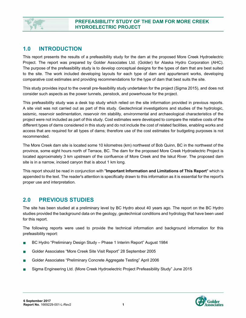
1.0 INTRODUCTION This report presents the results of a prefeasibility study for the dam at the proposed More Creek Hydroelectric Project. The report was prepared by Golder Associates Ltd. (Golder) for Alaska Hydro Corporation (AHC). The purpose of the prefeasibility study is to develop conceptual designs for the types of dam that are best suited to the site. The work included developing layouts for each type of dam and appurtenant works, developing comparative cost estimates and providing recommendations for the type of dam that best suits the site.
This study provides input to the overall pre-feasibility study undertaken for the project (Sigma 2015), and does not consider such aspects as the power tunnels, penstock, and powerhouse for the project.
This prefeasibility study was a desk top study which relied on the site information provided in previous reports. A site visit was not carried out as part of this study. Geotechnical investigations and studies of the hydrologic, seismic, reservoir sedimentation, reservoir rim stability, environmental and archaeological characteristics of the project were not included as part of this study. Cost estimates were developed to compare the relative costs of the different types of dams considered in this study and do not include the cost of related facilities, enabling works and access that are required for all types of dams; therefore use of the cost estimates for budgeting purposes is not recommended.
The More Creek dam site is located some 10 kilometres (km) northwest of Bob Quinn, BC in the northwest of the province, some eight hours north of Terrace, BC. The dam for the proposed More Creek Hydroelectric Project is located approximately 3 km upstream of the confluence of More Creek and the Iskut River. The proposed dam site is in a narrow, incised canyon that is about 1 km long.
This report should be read in conjunction with "Important Information and Limitations of This Report" which is appended to the text. The reader's attention is specifically drawn to this information as it is essential for the report's proper use and interpretation.
2.0 PREVIOUS STUDIES The site has been studied at a preliminary level by BC Hydro about 40 years ago. The report on the BC Hydro studies provided the background data on the geology, geotechnical conditions and hydrology that have been used for this report.
The following reports were used to provide the technical information and background information for this prefeasibility report:
BC Hydro “Preliminary Design Study – Phase 1 Interim Report” August 1984
Golder Associates “More Creek Site Visit Report” 28 September 2005
Golder Associates “Preliminary Concrete Aggregate Testing” April 2006
Sigma Engineering Ltd. (More Creek Hydroelectric Project Prefeasibility Study” June 2015

PREFEASIBILITY STUDY OF THE DAM FOR MORE CREEK HYDROELECTRIC PROJECT
6 September 2017 Report No. 1669229-001-L-Rev2 2
3.0 ASSUMPTIONS FOR PREFEASIBILITY STUDY This study focused on the type of dam that is best suited to the site, so it was necessary to rely on previous studies and make the following assumptions as the basis for this study.
3.1 Height of Dam and Reservoir Level BC Hydro (1984) studied a dam option with a height of 145 metres (m) with the reservoir level at el. 535 m, whereas the Golder site visit report (2005) considered a dam height of 75 m. For this study, the dam height was based on the same reservoir level (El 498 m) used for the pre-feasibility study (Sigma 2015), which results in a dam height of about 95 m.
It is our understanding that the construction camp for the Galore Mine is just above el. 500 m, so the conceptual dam designs developed for this study limit the reservoir flood rise to el. 500 m. It is recommended that the level of the Galore Mine construction camp, the level of the mine access road and other features of the impounded area (including environmental impacts) be verified before design of the project is developed further.
It should be noted that the dam site is suitable for a dam height of 150 m or higher.
3.2 Topography The canyon at the dam site is about 1 km long. More Creek has a “dog-leg” turn near the upstream end of the canyon and is straight through the downstream half of the canyon.
The slopes on both sides of the canyon are very steep with slope angles of 35° to 45°. The steep slopes extend from river level at about el. 405 m, to about el. 550 m.
The existing topographic maps of the site are coarse and the topography in the Prefeasibility Study (Sigma 2015) cannot be correlated with the topography in the BC Hydro Study (1984). The topography from the Sigma study was used as the basis for the layout of the dam options in this report. A detailed topographic survey (Lidar survey, or equivalent) is recommended for future studies.
3.3 Dam Alignment BC Hydro studied and investigated a dam site near the downstream end of the canyon while Golder (2005) and Sigma (2015) looked at a dam site near the upstream end – see Figure 1. While both the upstream and downstream sites appear to be suitable for construction of a large dam, the BC Hydro centerline (or downstream site) has been selected for this study for the following reasons:
The straight section through the downstream half of the canyon has more uniform topography so it is less likely to have unfavourable geologic structure (faults, shear zones, jointing). There is probably a geologic reason that the river does the “dog-leg” turn near the upstream end of the canyon.
Construction would be simpler in the straight section as the slopes are more uniform.
PREFEASIBILITY STUDY OF THE DAM FOR MORE CREEK HYDROELECTRIC PROJECT
6 September 2017 Report No. 1669229-001-L-Rev2 3
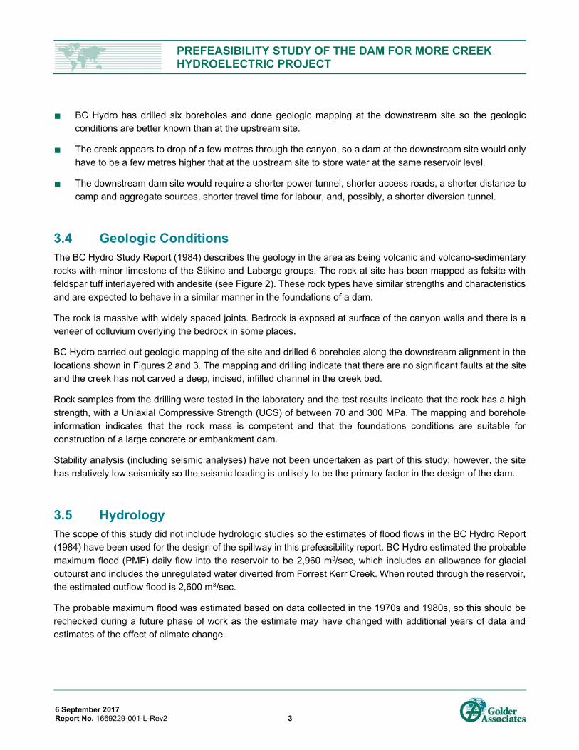
BC Hydro has drilled six boreholes and done geologic mapping at the downstream site so the geologic conditions are better known than at the upstream site.
The creek appears to drop of a few metres through the canyon, so a dam at the downstream site would only have to be a few metres higher that at the upstream site to store water at the same reservoir level.
The downstream dam site would require a shorter power tunnel, shorter access roads, a shorter distance to camp and aggregate sources, shorter travel time for labour, and, possibly, a shorter diversion tunnel.
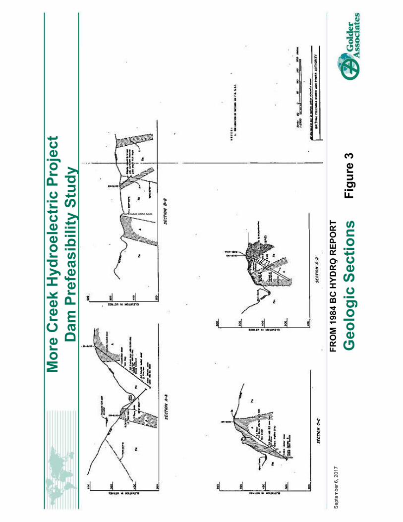
3.4 Geologic Conditions The BC Hydro Study Report (1984) describes the geology in the area as being volcanic and volcano-sedimentary rocks with minor limestone of the Stikine and Laberge groups. The rock at site has been mapped as felsite with feldspar tuff interlayered with andesite (see Figure 2). These rock types have similar strengths and characteristics and are expected to behave in a similar manner in the foundations of a dam.
The rock is massive with widely spaced joints. Bedrock is exposed at surface of the canyon walls and there is a veneer of colluvium overlying the bedrock in some places.
BC Hydro carried out geologic mapping of the site and drilled 6 boreholes along the downstream alignment in the locations shown in Figures 2 and 3. The mapping and drilling indicate that there are no significant faults at the site and the creek has not carved a deep, incised, infilled channel in the creek bed.
Rock samples from the drilling were tested in the laboratory and the test results indicate that the rock has a high strength, with a Uniaxial Compressive Strength (UCS) of between 70 and 300 MPa. The mapping and borehole information indicates that the rock mass is competent and that the foundations conditions are suitable for construction of a large concrete or embankment dam.
Stability analysis (including seismic analyses) have not been undertaken as part of this study; however, the site has relatively low seismicity so the seismic loading is unlikely to be the primary factor in the design of the dam.
3.5 Hydrology The scope of this study did not include hydrologic studies so the estimates of flood flows in the BC Hydro Report (1984) have been used for the design of the spillway in this prefeasibility report. BC Hydro estimated the probable maximum flood (PMF) daily flow into the reservoir to be 2,960 m3/sec, which includes an allowance for glacial outburst and includes the unregulated water diverted from Forrest Kerr Creek. When routed through the reservoir, the estimated outflow flood is 2,600 m3/sec.
The probable maximum flood was estimated based on data collected in the 1970s and 1980s, so this should be rechecked during a future phase of work as the estimate may have changed with additional years of data and estimates of the effect of climate change.

PREFEASIBILITY STUDY OF THE DAM FOR MORE CREEK HYDROELECTRIC PROJECT
6 September 2017 Report No. 1669229-001-L-Rev2 4
4.0 TYPES OF DAM The More Creek Canyon provides good conditions for the construction of several types of large dam. As part of this study, conceptual level designs were developed for the following types of dam:
Concrete Arch Dam
Roller Compacted Concrete (RCC) Dam
Earth/Rockfill Embankment Dam
Concrete Faced Rockfill Dam (CFRD)
Asphalt Core Rockfill Dam
5.0 SPILLWAY CONCEPTS In order to compare the various dam types, conceptual options for the spillway for each dam type was considered. To limit the rise in reservoir level during the design flood and to avoid inundating the construction camp for Galore Mine), the spillway for all dam types has been designed to have 3-20 m wide x 6 m high Obermeyer inflatable spillway gates. This maximum reservoir level during the passage of the PMF outflow (i.e., for the 10,000 year+ return period flood) of 2,600 m3/sec (BC Hydro 1984) is el. 500 m, i.e., this equates to 2 m of flood rise above the normal pool level of el. 498 m. The spillway can pass 66% of PMF with no flood rise, i.e., with reservoir at normal pool level and with the Obermeyer gates fully open.
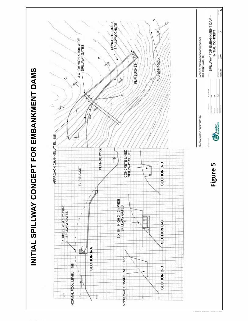
The first spillway design developed for this study used 3 -10 m wide x 10 m high spillway gates which reduces the width of the spillway channel and reduces the volume of rockfill excavation required for the spillway of embankment-type dams but it increases the cost of the spillway gates. Further evaluation and optimization of the spillway design will be required during the feasibility study level for the project.
5.1 Spillway for Embankment Dams The preliminary design for the spillway for embankment dams at the site is shown on Figure 4. The spillway has the following components:
an excavated approach channel
3-6 m high x 20 m wide Obermeyer gates on a concrete overflow crest
a 200-m long concrete lined chute
a flip bucket energy dissipater
a plunge pool in the river channel downstream

PREFEASIBILITY STUDY OF THE DAM FOR MORE CREEK HYDROELECTRIC PROJECT
6 September 2017 Report No. 1669229-001-L-Rev2 5
The topography on the left abutment is better suited to a spillway alignment than the right abutment as it requires less rock excavation. In addition, the supercritical flow does not need to change direction and the flow can be jetted directly into the river bed at the downstream end of the spillway chute.
The spillway channel would require a large volume of rock excavation with high cut faces up to 70 m high. The volume of excavation is approximately 700,000 m3 (bank), or 900,000 m3 (bulked). It is anticipated that the excavated rock could be used in the embankment dams, subject to further assessment of rock characteristics.
The initial concept had a 30-m wide crest, radial or slide gates and a smaller volume of excavation. When the preliminary design was changed, it was necessary to change the cross section of the earth/rockfill dam so that all the excavated rock could be used as rockfill in the dam embankment cross section. As mentioned above, further studies will be required to optimize the width of the spillway, type of spillway gates, volume of excavation and cross section of embankment dam
5.2 Spillway for Concrete and RCC Dams The spillway for concrete arch and RCC dams are more simple and cheaper than for embankment dams as the spillway flow can pass directly over the dam and return to the river bed at the toe of the dam.
As with the embankment dams, the spillway for arch and RCC has 3-6 m high x 20 m wide Obermeyer gates on an overflow crest.
6.0 CONCEPTUAL DESIGNS FOR DAMS Conceptual level designs were developed for the five types of dam. In the absence of detailed site information, a number of assumptions were developed; these assumptions and some notes related to the design concepts for each type of dam are listed below.
Concrete Arch Dam
The foundation excavation is 5 m into rock (to remove loose and stress relieved blocks of rock).
The 3 no. Obermeyer spillway gates are on the crest of the dam.
The spillway crest structure has a ski-jump-type lip and splitters to aerate the flow and dissipate the energy and to limit scour at the toe of the dam. The aerated flow falls to a concrete apron at the impact area.
The preliminary design (and quantity estimate) includes an upstream embankment cofferdam, however, there is potential to optimize the diversion concept to eliminate, or reduce the sizes of, the diversion tunnel and the cofferdam.
The layout and preliminary design of the arch dam are shown on Figure 6.
The prefeasibility design is based on “Guide to the Preliminary Design of Arch Dams” by USBR, Eng. Monograph No. 36, 1966.
PREFEASIBILITY STUDY OF THE DAM FOR MORE CREEK HYDROELECTRIC PROJECT
6 September 2017 Report No. 1669229-001-L-Rev2 6
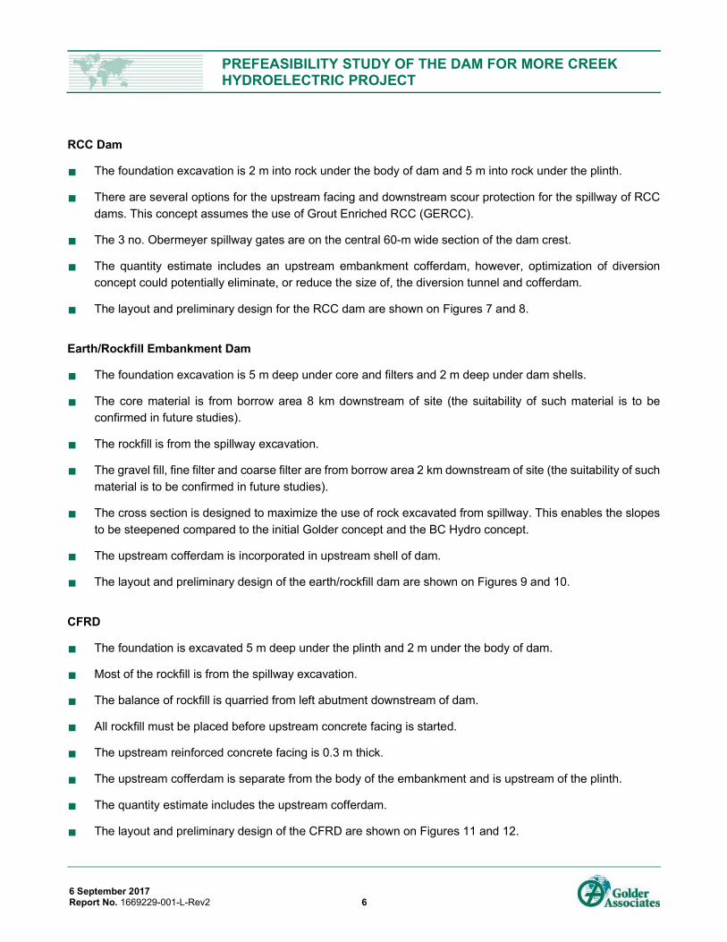
RCC Dam
The foundation excavation is 2 m into rock under the body of dam and 5 m into rock under the plinth.
There are several options for the upstream facing and downstream scour protection for the spillway of RCC dams. This concept assumes the use of Grout Enriched RCC (GERCC).
The 3 no. Obermeyer spillway gates are on the central 60-m wide section of the dam crest.
The quantity estimate includes an upstream embankment cofferdam, however, optimization of diversion concept could potentially eliminate, or reduce the size of, the diversion tunnel and cofferdam.
The layout and preliminary design for the RCC dam are shown on Figures 7 and 8.
Earth/Rockfill Embankment Dam
The foundation excavation is 5 m deep under core and filters and 2 m deep under dam shells.
The core material is from borrow area 8 km downstream of site (the suitability of such material is to be confirmed in future studies).
The rockfill is from the spillway excavation.
The gravel fill, fine filter and coarse filter are from borrow area 2 km downstream of site (the suitability of such material is to be confirmed in future studies).
The cross section is designed to maximize the use of rock excavated from spillway. This enables the slopes to be steepened compared to the initial Golder concept and the BC Hydro concept.
The upstream cofferdam is incorporated in upstream shell of dam.
The layout and preliminary design of the earth/rockfill dam are shown on Figures 9 and 10.
CFRD
The foundation is excavated 5 m deep under the plinth and 2 m under the body of dam.
Most of the rockfill is from the spillway excavation.
The balance of rockfill is quarried from left abutment downstream of dam.
All rockfill must be placed before upstream concrete facing is started.
The upstream reinforced concrete facing is 0.3 m thick.
The upstream cofferdam is separate from the body of the embankment and is upstream of the plinth.
The quantity estimate includes the upstream cofferdam.
The layout and preliminary design of the CFRD are shown on Figures 11 and 12.

PREFEASIBILITY STUDY OF THE DAM FOR MORE CREEK HYDROELECTRIC PROJECT
6 September 2017 Report No. 1669229-001-L-Rev2 7
Asphaltic Core
A layout and preliminary design of an asphaltic core dam was developed initially, as shown on Figures 13 and 14. However, after further consideration, this design was not developed further because this type of dam is not common in North America and, to our knowledge, none have been built in BC.
7.0 COMPARATIVE COST ESTIMATES For this prefeasibility study, comparative cost estimates were developed for arch, RCC, earth/rockfill and CFR dams. The following sections list the basis and assumptions for these comparative cost estimates.
Basis for Comparative Cost Estimating – General
The costs in the estimates are for comparative purposes only. They have been developed to assist in selecting the most cost effective type of dam for the site. They should NOT be used for budgeting as they stand.
As discussed earlier in this report, this study was specific to the dam, and excluded many other project elements. Many of these elements are common to all options, so have little effect in comparing costs for the various options. The costs for the following items are not included in the comparative cost estimates.
Diversion works (diversion tunnel, cofferdam, etc.)
a low level outlet to lower the reservoir and/or to pass sediment in the long term
the grout curtain, drainage works, etc. (considered to be similar for all options)
other project features, including,
the power tunnel
the powerhouse
access road to site
access roads around site and quarry areas
transmission lines
Cement has been estimated at $300/MT (based on recent delivery to Mt. Polley Mine Dam Rehab).
Suitable aggregates and borrow materials are available in the site borrow areas.
Limited processing costs for screening and washing the aggregates and the fine filter material are included where required.
Loading and hauling costs are included and vary depending on the quarry (approximately 3 km from the sand and gravel quarry, and 8 km for the earthfill dam core).

PREFEASIBILITY STUDY OF THE DAM FOR MORE CREEK HYDROELECTRIC PROJECT
6 September 2017 Report No. 1669229-001-L-Rev2 8
Concrete has been assumed to batched on-site. The batch plant will be setup close to the dam site in order to minimize concrete haul/pumping distance.
Supply and installation of Obermeyer Spillway Gates for all options estimated at $1,500,000 (based on recent run-of-river projects) + 15% mark up.
Loading of $25 per manhour is included for camp costs.
Loading of $5 per manhour is included for small tools and PPE.
Contractors markup (overhead and profits) are included in unit costs at 15%.
Indirect costs have been included separately in cost summary at 12% of direct costs. Indirect costs include the following items:
site supervision
construction / project management
temporary site facilities and utilities (offices, tool cans, washrooms etc.)
minor site equipment (generators, telehandlers, small pumps)
QA/QC costs are not included.
Engineering costs are not included.
Construction schedules have not yet been developed.
Comparative Costs for the Arch Dam
The concrete will be batched on-site and the batch plant will be close to the dam on left abutment.
The concrete will be pumped directly to dam from the batch plant using concrete pumps and line pumps.
Multiple crawler cranes and a tower crane will be used to construct the arch dam.
Comparative Costs for the RCC Dam
Large trucks will be used to haul the RCC directly from the pug mill (or batch plant) onto the fill.
Further studies may identify a conveyor system as being more suitable for hauling the RCC.
The aggregate will be hauled from the borrow area 2 km from the site.
The aggregate will require screening and washing.

PREFEASIBILITY STUDY OF THE DAM FOR MORE CREEK HYDROELECTRIC PROJECT
6 September 2017 Report No. 1669229-001-L-Rev2 9
Comparative Costs for the Earth Rockfill Dam
Blasted rock from spillway excavation will be hauled directly to the dam for placement in the upstream and downstream shells without stockpiling.
Gravel fill and core material will be placed in thin lifts (as with conventional fill).
Rockfill will be placed in 1 m thick lifts.
Concrete in spillway will be pumped from batch plant.
Earthfill and rockfill will be hauled by truck, and placed with dozers and compactors.
Comparative Costs for the CFR Dam
Blasted rock from spillway excavation will be hauled directly to the dam for placement in the body of the dam without stockpiling.
The transition zones will be placed in thin lifts (as with conventional fill).
Rockfill will be placed in 1-m thick lifts.
Rockfill will be hauled by truck.
Concrete in spillway and upstream facing will be pumped from batch plant.
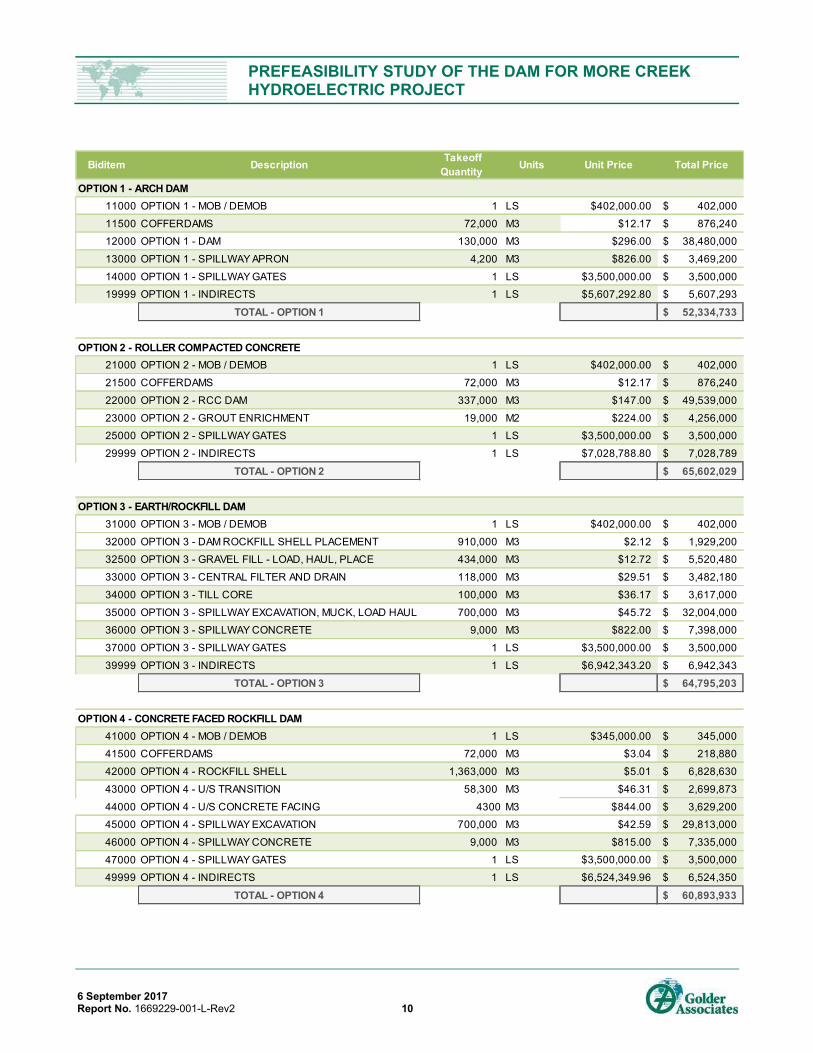
Cost Comparisons
Using the assumptions listed above, the following table compares the relative costs of the arch, RCC, earth/rockfill and CFR dams.
PREFEASIBILITY STUDY OF THE DAM FOR MORE CREEK HYDROELECTRIC PROJECT
6 September 2017 Report No. 1669229-001-L-Rev2 10
Biditem Description Takeoff Quantity Units Unit Price Total Price
OPTION 1 - ARCH DAM11000 OPTION 1 - MOB / DEMOB 1 LS $402,000.00 402,000$
11500 COFFERDAMS 72,000 M3 $12.17 876,240$
12000 OPTION 1 - DAM 130,000 M3 $296.00 38,480,000$
13000 OPTION 1 - SPILLWAY APRON 4,200 M3 $826.00 3,469,200$
14000 OPTION 1 - SPILLWAY GATES 1 LS $3,500,000.00 3,500,000$
19999 OPTION 1 - INDIRECTS 1 LS $5,607,292.80 5,607,293$
TOTAL - OPTION 1 52,334,733$
OPTION 2 - ROLLER COMPACTED CONCRETE21000 OPTION 2 - MOB / DEMOB 1 LS $402,000.00 402,000$
21500 COFFERDAMS 72,000 M3 $12.17 876,240$
22000 OPTION 2 - RCC DAM 337,000 M3 $147.00 49,539,000$
23000 OPTION 2 - GROUT ENRICHMENT 19,000 M2 $224.00 4,256,000$
25000 OPTION 2 - SPILLWAY GATES 1 LS $3,500,000.00 3,500,000$
29999 OPTION 2 - INDIRECTS 1 LS $7,028,788.80 7,028,789$
TOTAL - OPTION 2 65,602,029$
OPTION 3 - EARTH/ROCKFILL DAM31000 OPTION 3 - MOB / DEMOB 1 LS $402,000.00 402,000$
32000 OPTION 3 - DAM ROCKFILL SHELL PLACEMENT 910,000 M3 $2.12 1,929,200$
32500 OPTION 3 - GRAVEL FILL - LOAD, HAUL, PLACE 434,000 M3 $12.72 5,520,480$
33000 OPTION 3 - CENTRAL FILTER AND DRAIN 118,000 M3 $29.51 3,482,180$
34000 OPTION 3 - TILL CORE 100,000 M3 $36.17 3,617,000$
35000 OPTION 3 - SPILLWAY EXCAVATION, MUCK, LOAD HAUL 700,000 M3 $45.72 32,004,000$
36000 OPTION 3 - SPILLWAY CONCRETE 9,000 M3 $822.00 7,398,000$
37000 OPTION 3 - SPILLWAY GATES 1 LS $3,500,000.00 3,500,000$
39999 OPTION 3 - INDIRECTS 1 LS $6,942,343.20 6,942,343$
TOTAL - OPTION 3 64,795,203$
OPTION 4 - CONCRETE FACED ROCKFILL DAM41000 OPTION 4 - MOB / DEMOB 1 LS $345,000.00 345,000$
41500 COFFERDAMS 72,000 M3 $3.04 218,880$
42000 OPTION 4 - ROCKFILL SHELL 1,363,000 M3 $5.01 6,828,630$
43000 OPTION 4 - U/S TRANSITION 58,300 M3 $46.31 2,699,873$
44000 OPTION 4 - U/S CONCRETE FACING 4300 M3 $844.00 3,629,200$
45000 OPTION 4 - SPILLWAY EXCAVATION 700,000 M3 $42.59 29,813,000$
46000 OPTION 4 - SPILLWAY CONCRETE 9,000 M3 $815.00 7,335,000$
47000 OPTION 4 - SPILLWAY GATES 1 LS $3,500,000.00 3,500,000$
49999 OPTION 4 - INDIRECTS 1 LS $6,524,349.96 6,524,350$
TOTAL - OPTION 4 60,893,933$

PREFEASIBILITY STUDY OF THE DAM FOR MORE CREEK HYDROELECTRIC PROJECT
6 September 2017 Report No. 1669229-001-L-Rev2 11
The comparative cost estimate for the RCC, earth/rockfill and CFR dams are within about 7% of each other. The estimate for the arch dam is about 20% less than the other three types of dam. The four estimates are remarkably close to one another and the differences are well within the range of accuracy of the cost estimates. A similar spread in bid prices for the construction of any type of large dam could be expected. However, the arch dam appears to be the most economic type of dam for the More Creek site.
8.0 RECOMMENDED TYPE OF DAM Arch dams have become less common in the last 30 years. This may be because arch dams are particularly well suited to narrow, steep sided valleys where good rock is close to the surface and most of these types of dam sites around the world have been had dams built in them already.
The More Creek site does have these favourable conditions so the site is well suited to the construction of an arch dam. In addition, an arch dam offers the following potential for further reducing the cost compared to the design shown in Figure 7:
It may be possible to significantly reduce the size of the cofferdam and the length of the diversion tunnel. Alternatively, it may be possible to construct a small concrete cofferdam and eliminate the diversion tunnel by diverting low flows into pipes through the dam and diverting high flows over partially constructed blocks of the dam. A more detailed study of the hydrology, topography and construction sequence will be required to optimize the diversion scheme.
It may be possible to eliminate the spillway apron, depending on a more detailed evaluation of the erodibility of the rock at the toe of the dam.
A low level outlet to lower the reservoir after an earthquake could be more economically included into an arch dam than into the other types of dam.
The same low level outlet could be used to pass sediment if subsequent reservoir sedimentation studies indicate that this could be required for long term sustainability of the project.
9.0 SUMMARY The summary and recommendations from the assessment of the dam site, the preliminary dam designs, and the comparative cost estimates for this prefeasibility study can be summarized as follows:
The site has favorable topography and geology for the construction of a high dam.
The site is suitable for several types of dam.
The steep topography favors concrete dams which can incorporate the spillway over the dam.
In this steep topography, embankment dams require large rock excavations for the spillway on one of the abutments.
For embankment dams, the left abutment is more suitable for the spillway than the right abutment.
Comparative costs vary from $52.3 M (Arch Dam) to $65.6 M (for RCC Dam).
Bid prices on large dams often vary by at least this percentage.

PREFEASIBILITY STUDY OF THE DAM FOR MORE CREEK HYDROELECTRIC PROJECT
As stated above, the range of estimates between the four dam types is well within the accuracy of the estimates, so a preferred option should not be made at this stage based on cost alone. In addition, th is study has not considered other factors (environmental, archaeological, etc.) which may have a bearing on the preferred dam type . However, it is understood that it is preferred to reduce the number of dam types under consideration, and identify a single option to be carried forward to further study. Based on this study, an arch dam is considered to be the preferred option to be carried forward to the next level of investigations and design because it has the lowest estimated cost and an arch dam has the greatest potential to reduce costs by optimizing the diversion scheme and minimizing the cost of a low level outlet. Should further study identify factors that increase the complexity, or cost of the arch dam, it may be necessary to revisit one or more of the other dam types.
10.0 CLOSURE We trust the information contained in this report is sufficient for your present needs. Should you have any additional questions regarding the project, please do not hesitate to contact the undersigned.
GOLDER ASSOCIATES L TO.
Richard Humphries, PEng Senior Consultant
BD/ RH/Iih
Reviewed by
Bruce Downing, PEng Principal
Golder, Golder Associates and the GA globe design are t rademarks of Golder Associates Corporation.
https:l/golderassociates. sharepoinl comlsites/15072g/deliverablesflssued to clienV1669229-001-r -rev2/1669229-001-< -rev2-more creek report 06sep _17.dOCJ<
6 September 2017 Report No. 1669229-001-L-Rev2 12
.;ji:.
f!A' Gol<{er \U AssOCiates

PREFEASIBILITY STUDY OF THE DAM FOR MORE CREEK HYDROELECTRIC PROJECT
6 September 2017 Report No. 1669229-001-L-Rev2
APPENDIX A Figures 1 though 14

Mor
e C
reek
Hyd
roel
ectr
ic P
roje
ct
Rep
ort C
over
Pho
to

FIG
UR
E
CO
NS
ULT
ANT
TITL
EYY
YY-M
M-D
D
PR
EPA
RED
DE
SIG
N
RE
VIE
WR
ev AP
RO
JEC
TN
o16
6922
9P
HA
SE
2000
APP
RO
VED
Path: document1 | File Name: DOCUMENT1
ALA
SKA
HYD
RO
CO
RP
OR
ATI
ON
MO
RE
CR
EEK
HYD
RO
PO
WER
PR
OJE
CT
BO
B Q
UIN
N L
AKE
, BC
BC
HYD
RO
C
ENTR
ELI
NE
~145
m H
IGH
(198
4)
SIG
MA
CEN
TRE
LIN
E~9
0 m
HIG
H (2
016)
GO
LDER
CEN
TRE
LIN
E~7
5 m
HIG
H (2
005)
PR
OPO
SED
DA
M A
LIG
NM
EN
TC
AR
2015
-06-
27
RH
RH
1
Figu
re1

Sep
tem
ber 6
, 201
72
BC
HYD
RO
DA
MA
LIG
NM
ENT
APP
RO
X. 2
016
AN
D 2
005
DA
MA
LIG
NM
ENT
Mor
e C
reek
Hyd
roel
ectr
ic P
roje
ctD
am P
refe
asib
ility
Stu
dy
Geo
logi
c Pl
an
FRO
M 1
984
BC
HYD
RO
REP
OR
T
Figu
re 2
Sep
tem
ber 6
, 201
73
Mor
e C
reek
Hyd
roel
ectr
ic P
roje
ctD
am P
refe
asib
ility
Stu
dy
Geo
logi
c Se
ctio
nsFR
OM
198
4 B
C H
YDR
O R
EPO
RT
Figu
re 3

FIGURE
CONSULTANT TITLEYYYY-MM-DD
PREPARED
DESIGN
REVIEW Rev
APROJECT No1669229
PHASE
2000APPROVEDPat
h: d
ocum
ent1
| F
ile N
ame:
DO
CU
ME
NT1
ALASKA HYDRO CORPORATION MORE CREEK HYDROPOWER PROJECTBOB QUINN LAKE, BC
SPILLWAY FOR EMBANKMENT DAM –CONCEPTUAL LAYOUT
RH
2015-06-26
RH
CAR
4
Figure 4
- ··--------
~,Goldu w~
FIG
UR
E
CO
NS
ULT
ANT
TITL
EYY
YY-M
M-D
D
PR
EPA
RED
DE
SIG
N
RE
VIE
WR
ev AP
RO
JEC
TN
o16
6922
9P
HA
SE
2000
APP
RO
VED
Path: document1 | File Name: DOCUMENT1
ALA
SKA
HYD
RO
CO
RP
OR
ATI
ON
MO
RE
CR
EEK
HYD
RO
PO
WER
PR
OJE
CT
BO
B Q
UIN
N L
AKE
, BC
SP
ILLW
AY F
OR
EM
BA
NK
ME
NT
DA
M –
INIT
IAL
CO
NC
EP
T
CO
NC
RE
TE L
INE
D
SP
ILLW
AY C
HU
TE
3 X
10m
HIG
H X
10m
WID
E
SP
ILLW
AY G
ATE
S
NO
RM
AL
PO
OL
LEV
EL
= 49
8m
FLIP
BU
CK
ET
AP
PR
OA
CH
CH
AN
NE
L AT
EL.
485
3 X
10m
HIG
H X
10m
WID
E
SP
ILLW
AY G
ATE
S
3 X
10m
HIG
H X
10m
WID
E
SP
ILLW
AY G
ATE
S
CO
NC
RE
TE L
INE
D
SP
ILLW
AY C
HU
TE
AP
PR
OA
CH
CH
AN
NE
L AT
EL.
485
FLIP
BU
CK
ET
PLU
NG
E P
OO
L
PLU
NG
E P
OO
L
A
A
B
B
C
C D
D
SEC
TIO
N B
-BSE
CTI
ON
D-D
SEC
TIO
N C
-C
SEC
TIO
N A
-A
RH2015
-06-
26
RH
CA
R
5
INIT
IAL
SPIL
LWAY
CO
NC
EPT
FOR
EM
BA
NK
MEN
T D
AM
S
Figu
re5

FIG
UR
E
CO
NS
ULT
ANT
TITL
EYY
YY-M
M-D
D
PR
EPA
RED
DE
SIG
N
RE
VIE
WR
ev AP
RO
JEC
TN
o16
6922
9P
HA
SE
2000
APP
RO
VED
Path: document1 | File Name: DOCUMENT1
ALA
SKA
HYD
RO
CO
RP
OR
ATI
ON
MO
RE
CR
EEK
HYD
RO
PO
WER
PR
OJE
CT
BO
B Q
UIN
N L
AKE
, BC
OB
ER
ME
YER
G
ATE
D
SP
ILLW
AY
UPS
TRE
AM
C
OFF
ER
DA
M
AR
CH
DA
M
SP
ILLW
AY
AP
RO
N
SP
ILLW
AY
AP
RO
N
LOW
LE
VE
L O
UTL
ET
DO
WN
STR
EA
M
CO
FFE
RD
AM
DIV
ER
SIO
NTU
NN
EL
PO
WE
R T
UN
NE
L
PO
WE
RH
OU
SE
NO
RM
AL
PO
OL
= 49
8mC
RE
ST
LEV
EL
= 5
00m
AR
CH
DA
M –
CO
NC
EP
TUA
L LA
YOU
T
RA
DIU
S =
138
m
6
AR
CH
DA
M C
ON
CEP
T
Figu
re6

FIG
UR
E
CO
NS
ULT
ANT
TITL
EYY
YY-M
M-D
D
PR
EPA
RED
DE
SIG
N
RE
VIE
WR
ev AP
RO
JEC
TN
o16
6922
9P
HA
SE
2000
APP
RO
VED
Path: document1 | File Name: DOCUMENT1
ALA
SKA
HYD
RO
CO
RP
OR
ATI
ON
MO
RE
CR
EEK
HYD
RO
PO
WER
PR
OJE
CT
BO
B Q
UIN
N L
AKE
, BC
RC
C D
AM
–C
ON
CE
PTU
AL
LAYO
UT
UPS
TRE
AM
C
OFF
ER
DA
M
DIV
ER
SIO
NTU
NN
EL
PO
WE
R T
UN
NE
L
PO
WE
RH
OU
SE
SP
ILLW
AY C
HU
TE
ON
DO
WN
STR
EA
M
FAC
ED
OW
NS
TRE
AM
C
OFF
ER
DA
M
3 N
o. O
BE
RM
EYE
R
GAT
ES
6m
x 2
0m O
N
CR
ES
T
RC
C D
AM
7
RC
C D
AM
CO
NC
EPT
Figu
re7

FIG
UR
E
CO
NS
ULT
ANT
TITL
EYY
YY-M
M-D
D
PR
EPA
RED
DE
SIG
N
RE
VIE
WR
ev AP
RO
JEC
TN
o16
6922
9P
HA
SE
2000
APP
RO
VED
Path: document1 | File Name: DOCUMENT1
ALA
SKA
HYD
RO
CO
RP
OR
ATI
ON
MO
RE
CR
EEK
HYD
RO
PO
WER
PR
OJE
CT
BO
B Q
UIN
N L
AKE
, BC
NO
N-O
VER
FLO
W S
ECTI
ON
NO
RM
AL
PO
OL
= 49
8mN
ON
-OV
ER
FLO
W C
RE
ST
= 50
0m0.
3m R
CC
LIF
T H
EIG
HT
SPIL
LWAY
SEC
TIO
N
0.3m
RC
C L
IFT
HE
IGH
T
GE
-RC
C U
PS
TRE
AM
FA
CE
GE
-RC
C S
TEP
FAC
ING
RC
C D
AM
–C
ON
CE
PTU
AL
CR
OS
S S
EC
TIO
N
GE
-RC
CU
PS
TRE
AM
FA
CE
3 N
o. O
BE
RM
EYE
R
GAT
ES
6m
x 2
0m O
N
CR
ES
T
GR
OU
T C
UR
TAIN
8
Figu
re8
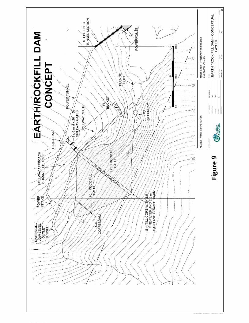
FIG
UR
E
CO
NS
ULT
ANT
TITL
EYY
YY-M
M-D
D
PR
EPA
RED
DE
SIG
N
RE
VIE
WR
ev AP
RO
JEC
TN
o16
6922
9P
HA
SE
2000
APP
RO
VED
Path: document1 | File Name: DOCUMENT1
ALA
SKA
HYD
RO
CO
RP
OR
ATI
ON
MO
RE
CR
EEK
HYD
RO
PO
WER
PR
OJE
CT
BO
B Q
UIN
N L
AKE
, BC
1.75
:1 R
OC
K F
ILL
U/S
SH
ELL
1.75
:1 R
OC
K F
ILL
D/S
SH
ELL
U/S
CO
FFE
RD
AM
D/S
CO
FFE
RD
AM
3 x
6m
H x
20
m W
S
PIL
LWAY
GAT
ES
SP
ILLW
AY C
HU
TE
FLIP
B
UC
KE
T
PLU
NG
EP
OO
L EA
RTH
/ R
OC
K F
ILL
DA
M –
CO
NC
EP
TUA
L LA
YOU
T
8 m
TIL
L C
OR
E W
ITH
2.5
m
FIN
E F
ILTE
R A
ND
2.5
m
SA
ND
AN
D G
RAV
EL
DR
AIN
PO
WE
R T
UN
NE
L
GAT
E S
HA
FT
PO
WE
R
INTA
KE
STE
EL
LIN
ED
TU
NN
EL
SE
CTI
ON
PO
WE
RH
OU
SE
DIV
ER
SIO
N /
LOW
LE
VE
L O
UTL
ET
TUN
NEL
600
m0
m10
0 m
200
m
SP
ILLW
AY A
PP
RO
AC
H
CH
AN
NE
L E
L. 4
85 m
CA
R
2015
-06-
26
CA
R
RH
9
EAR
TH/R
OC
KFI
LL D
AM
C
ON
CEP
T
Figu
re9
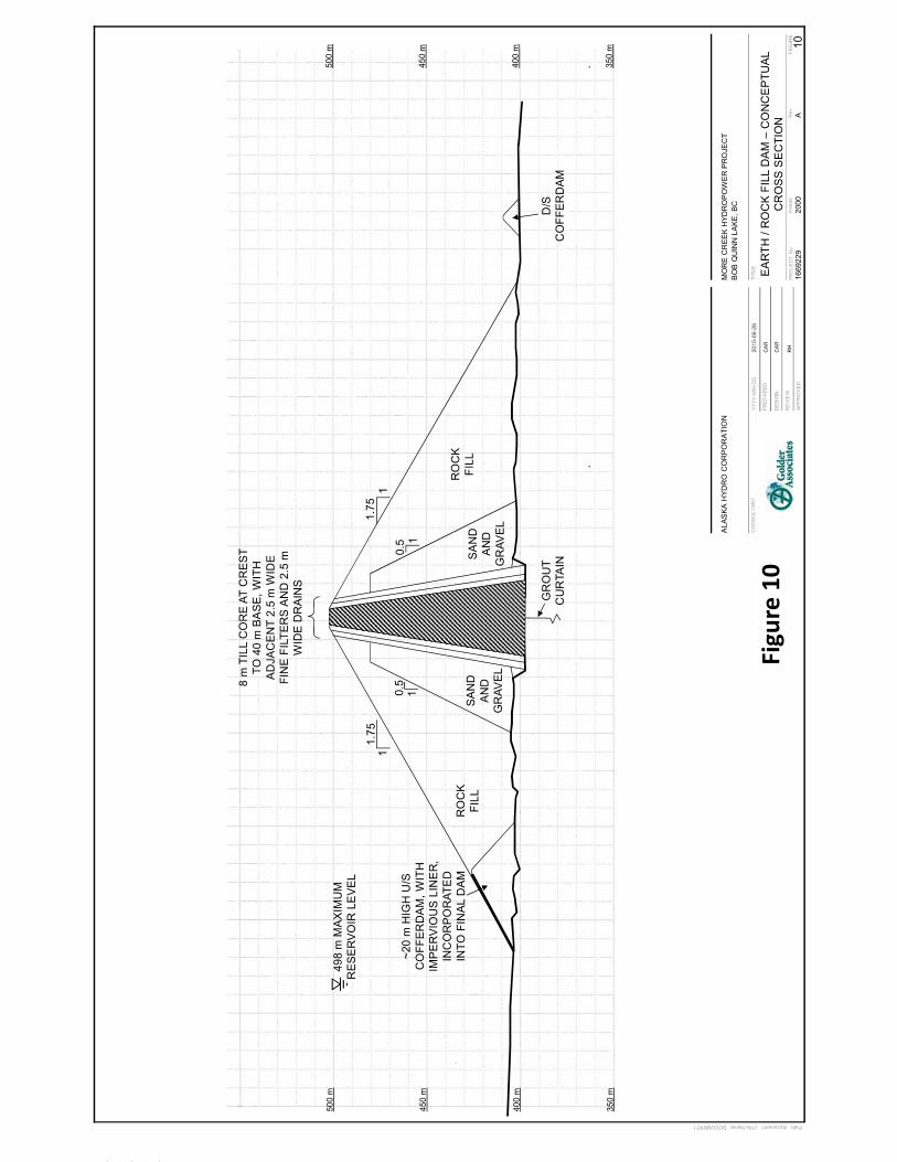
FIG
UR
E
CO
NS
ULT
ANT
TITL
EYY
YY-M
M-D
D
PR
EPA
RED
DE
SIG
N
RE
VIE
WR
ev AP
RO
JEC
TN
o16
6922
9P
HA
SE
2000
APP
RO
VED
Path: document1 | File Name: DOCUMENT1
ALA
SKA
HYD
RO
CO
RP
OR
ATI
ON
MO
RE
CR
EEK
HYD
RO
PO
WER
PR
OJE
CT
BO
B Q
UIN
N L
AKE
, BC
EA
RTH
/ R
OC
K F
ILL
DA
M –
CO
NC
EP
TUA
L C
RO
SS
SE
CTI
ON
1.75
11
1.75
GR
OU
T C
UR
TAIN
498
m M
AX
IMU
M
RE
SE
RV
OIR
LE
VE
L
D/S
CO
FFE
RD
AM
SA
ND
AN
DG
RAV
EL
SA
ND
AN
DG
RAV
EL
8 m
TIL
L C
OR
E A
T C
RE
ST
TO 4
0 m
BA
SE
, WIT
H
AD
JAC
EN
T 2.
5 m
WID
E
FIN
E F
ILTE
RS
AN
D 2
.5 m
W
IDE
DR
AIN
S
400
m
450
m
500
m
350
m
400
m
450
m
500
m
350
m
RO
CK
FILL
~20
m H
IGH
U/S
C
OFF
ER
DA
M, W
ITH
IM
PE
RV
IOU
S L
INE
R,
INC
OR
PO
RAT
ED
IN
TO F
INA
L D
AM
CA
R
2015
-06-
26
CA
R
RH
10
RO
CK
FILL
10.
510.
5
Figu
re10

FIG
UR
E
CO
NS
ULT
ANT
TITL
EYY
YY-M
M-D
D
PR
EPA
RED
DE
SIG
N
RE
VIE
WR
ev AP
RO
JEC
TN
o16
6922
9P
HA
SE
2000
APP
RO
VED
Path: document1 | File Name: DOCUMENT1
ALA
SKA
HYD
RO
CO
RP
OR
ATI
ON
MO
RE
CR
EEK
HYD
RO
PO
WER
PR
OJE
CT
BO
B Q
UIN
N L
AKE
, BC
1.5:
1 R
OC
K F
ILL
D/S
SH
ELL
U/S
CO
FFE
RD
AM
D/S
CO
FFE
RD
AM
SP
ILLW
AY C
HU
TE
FLIP
B
UC
KE
T
PLU
NG
EP
OO
L
CO
NC
RE
TE F
AC
ED
RO
CK
FILL
DA
M –
CO
NC
EP
TUA
L LA
YOU
T
PO
WE
R T
UN
NE
L
GAT
E S
HA
FT
PO
WE
R
INTA
KE
PO
WE
RH
OU
SE
DIV
ER
SIO
N /
LOW
LE
VE
L O
UTL
ET
TUN
NEL
600
m
STE
EL
LIN
ED
TU
NN
EL
SE
CTI
ON
0 m
100
m20
0 m
1.6:
1 C
ON
CR
ETE
FA
CE
D
U/S
RO
CK
FIL
L S
LOP
E
SP
ILLW
AY A
PP
RO
AC
H
CH
AN
NE
L E
L. 4
85 m
CA
R
2015
-06-
26
CA
R
RH
11
3 x
6m
H x
20
m W
S
PIL
LWAY
GAT
ES
CFR
DC
ON
CEP
T
Figu
re11

FIG
UR
E
CO
NS
ULT
ANT
TITL
EYY
YY-M
M-D
D
PR
EPA
RED
DE
SIG
N
RE
VIE
WR
ev AP
RO
JEC
TN
o16
6922
9P
HA
SE
2000
APP
RO
VED
Path: document1 | File Name: DOCUMENT1
ALA
SKA
HYD
RO
CO
RP
OR
ATI
ON
MO
RE
CR
EEK
HYD
RO
PO
WER
PR
OJE
CT
BO
B Q
UIN
N L
AKE
, BC
CO
NC
RE
TE F
AC
ED
RO
CK
FILL
DA
M –
CO
NC
EP
TUA
L C
RO
SS
SE
CTI
ON
RO
CK
FIL
L
5m
WID
E
TRA
NS
ITIO
N Z
ON
E
0.3
m T
HIC
K
CO
NC
RE
TEFA
CIN
G
1.6
11
1.5
498
m M
AX
IMU
M
RE
SE
RV
OIR
LE
VE
L
D/S
CO
FFE
RD
AM
400
m
450
m
500
m
350
m
400
m
450
m
500
m
350
m
GR
OU
T C
UR
TAIN
11.
51
1.5
~20
m H
IGH
U
/SC
OFF
ER
DA
M, W
ITH
IM
PE
RV
IOU
S L
INE
R
RO
CK
FILL
CA
R
2015
-06-
26
CA
R
RH
12
Figu
re12

FIG
UR
E
CO
NS
ULT
ANT
TITL
EYY
YY-M
M-D
D
PR
EPA
RED
DE
SIG
N
RE
VIE
WR
ev AP
RO
JEC
TN
o16
6922
9P
HA
SE
2000
APP
RO
VED
Path: document1 | File Name: DOCUMENT1
ALA
SKA
HYD
RO
CO
RP
OR
ATI
ON
MO
RE
CR
EEK
HYD
RO
PO
WER
PR
OJE
CT
BO
B Q
UIN
N L
AKE
, BC
SP
ILLW
AY C
HU
TE
FLIP
B
UC
KE
T
PLU
NG
EP
OO
L AS
PH
ALT
IC C
OR
E D
AM
–C
ON
CE
PTU
AL
LAYO
UT
0.8
m A
SP
HA
LTIC
CO
RE
A
ND
WIT
H 1
.8 m
TR
AN
SIT
ION
ZO
NE
S2.25
:1 C
OM
PAC
TED
S
AN
D A
ND
GR
AVE
L U
/S S
HE
LL 2:1
CO
MPA
CTE
D S
AN
D
AN
D G
RAV
EL
D/S
SH
ELL
PO
WE
R T
UN
NE
L
GAT
E S
HA
FT
PO
WE
R
INTA
KE
PO
WE
RH
OU
SE
DIV
ER
SIO
N /
LOW
LE
VE
L O
UTL
ET
TUN
NEL
600
m
STE
EL
LIN
ED
TU
NN
EL
SE
CTI
ON
0 m
100
m20
0 m
SP
ILLW
AY A
PP
RO
AC
H
CH
AN
NE
L E
L. 4
85 m
CA
R
2015
-06-
26
CA
R
RH
13
U/S
CO
FFE
RD
AM
D/S
CO
FFE
RD
AM
3 x
6m
H x
20
m W
S
PIL
LWAY
GAT
ES
ASP
HA
LT C
OR
E D
AM
(N
OT
CO
STED
)
Figu
re13

FIG
UR
E
CO
NS
ULT
ANT
TITL
EYY
YY-M
M-D
D
PR
EPA
RED
DE
SIG
N
RE
VIE
WR
ev AP
RO
JEC
TN
o16
6922
9P
HA
SE
2000
APP
RO
VED
Path: document1 | File Name: DOCUMENT1
ALA
SKA
HYD
RO
CO
RP
OR
ATI
ON
MO
RE
CR
EEK
HYD
RO
PO
WER
PR
OJE
CT
BO
B Q
UIN
N L
AKE
, BC
AS
PH
ALT
IC C
OR
E D
AM
–C
ON
CE
PTU
AL
CR
OS
S S
EC
TIO
N
2.25
11
2
498
m M
AX
IMU
M
RE
SE
RV
OIR
LE
VE
L
D/S
CO
FFE
RD
AM
U/S
SA
ND
AN
D
GR
AVE
L S
HE
LL
D/S
SA
ND
AN
D
GR
AVE
L S
HE
LL
0.8
m A
SP
HA
LTIC
CO
RE
, W
ITH
AD
JAC
EN
T 1.
8 m
TR
AN
SIT
ION
ZO
NE
S
400
m
450
m
500
m
350
m
400
m
450
m
500
m
350
m
GR
OU
T C
UR
TAIN
RO
CK
FILL
~20
m H
IGH
U/S
CO
FFE
RD
AM
, W
ITH
IMP
ER
VIO
US
LIN
ER
, IN
CO
RP
OR
ATE
D IN
TO F
INA
L D
AM
CA
R
2015
-06-
26
CA
R
RH
14
RO
CK
FILL
ASP
HA
LT C
OR
E D
AM
(N
OT
CO
STED
)
Figu
re14

PREFEASIBILITY STUDY OF THE DAM FOR MORE CREEK HYDROELECTRIC PROJECT
6 September 2017 Report No. 1669229-001-L-Rev2
APPENDIX B Important Information and Limitations of This Report

APPENDIX B IMPORTANT INFORMATION AND LIMITATIONS OF THIS REPORT
6 September 2017 Report No. 1669229-001-L-Rev2 B-1
Standard of Care: Golder Associates Ltd. (Golder) has prepared this report in a manner consistent with that level of care and skill ordinarily exercised by members of the engineering and science professions currently practising under similar conditions in the jurisdiction in which the services are provided, subject to the time limits and physical constraints applicable to this report. No other warranty, expressed or implied is made.
Basis and Use of the Report: This report has been prepared for the specific site, design objective, development and purpose described to Golder by the Client. The factual data, interpretations and recommendations pertain to a specific project as described in this report and are not applicable to any other project or site location. Any change of site conditions, purpose, development plans or if the project is not initiated within eighteen months of the date of the report may alter the validity of the report. Golder can not be responsible for use of this report, or portions thereof, unless Golder is requested to review and, if necessary, revise the report.
The information, recommendations and opinions expressed in this report are for the sole benefit of the Client. No other party may use or rely on this report or any portion thereof without Golder’s express written consent. If the report was prepared to be included for a specific permit application process, then upon the reasonable request of the client, Golder may authorize in writing the use of this report by the regulatory agency as an Approved User for the specific and identified purpose of the applicable permit review process. Any other use of this report by others is prohibited and is without responsibility to Golder. The report, all plans, data, drawings and other documents as well as all electronic media prepared by Golder are considered its professional work product and shall remain the copyright property of Golder, who authorizes only the Client and Approved Users to make copies of the report, but only in such quantities as are reasonably necessary for the use of the report by those parties. The Client and Approved Users may not give, lend, sell, or otherwise make available the report or any portion thereof to any other party without the express written permission of Golder. The Client acknowledges that electronic media is susceptible to unauthorized modification, deterioration and incompatibility and therefore the Client cannot rely upon the electronic media versions of Golder’s report or other work products.
The report is of a summary nature and is not intended to stand alone without reference to the instructions given to Golder by the Client, communications between Golder and the Client, and to any other reports prepared by Golder for the Client relative to the specific site described in the report. In order to properly understand the suggestions, recommendations and opinions expressed in this report, reference must be made to the whole of the report. Golder can not be responsible for use of portions of the report without reference to the entire report.
Unless otherwise stated, the suggestions, recommendations and opinions given in this report are intended only for the guidance of the Client in the design of the specific project. The extent and detail of investigations, including the number of test holes, necessary to determine all of the relevant conditions which may affect construction costs would normally be greater than has been carried out for design purposes. Contractors bidding on, or undertaking the work, should rely on their own investigations, as well as their own interpretations of the factual data presented in the report, as to how subsurface conditions may affect their work, including but not limited to proposed construction techniques, schedule, safety and equipment capabilities.
Soil, Rock and Groundwater Conditions: Classification and identification of soils, rocks, and geologic units have been based on commonly accepted methods employed in the practice of geotechnical engineering and related disciplines. Classification and identification of the type and condition of these materials or units involves judgment, and boundaries between different soil, rock or geologic types or units may be transitional rather than abrupt. Accordingly, Golder does not warrant or guarantee the exactness of the descriptions.

APPENDIX B IMPORTANT INFORMATION AND LIMITATIONS OF THIS REPORT
6 September 2017 Report No. 1669229-001-L-Rev2 B-2
Special risks occur whenever engineering or related disciplines are applied to identify subsurface conditions and even a comprehensive investigation, sampling and testing program may fail to detect all or certain subsurface conditions. The environmental, geologic, geotechnical, geochemical and hydrogeologic conditions that Golder interprets to exist between and beyond sampling points may differ from those that actually exist. In addition to soil variability, fill of variable physical and chemical composition can be present over portions of the site or on adjacent properties. The professional services retained for this project include only the geotechnical aspects of the subsurface conditions at the site, unless otherwise specifically stated and identified in the report. The presence or implication(s) of possible surface and/or subsurface contamination resulting from previous activities or uses of the site and/or resulting from the introduction onto the site of materials from off-site sources are outside the terms of reference for this project and have not been investigated or addressed.
Soil and groundwater conditions shown in the factual data and described in the report are the observed conditions at the time of their determination or measurement. Unless otherwise noted, those conditions form the basis of the recommendations in the report. Groundwater conditions may vary between and beyond reported locations and can be affected by annual, seasonal and meteorological conditions. The condition of the soil, rock and groundwater may be significantly altered by construction activities (traffic, excavation, groundwater level lowering, pile driving, blasting, etc.) on the site or on adjacent sites. Excavation may expose the soils to changes due to wetting, drying or frost. Unless otherwise indicated the soil must be protected from these changes during construction.
Sample Disposal: Golder will dispose of all uncontaminated soil and/or rock samples 90 days following issue of this report or, upon written request of the Client, will store uncontaminated samples and materials at the Client’s expense. In the event that actual contaminated soils, fills or groundwater are encountered or are inferred to be present, all contaminated samples shall remain the property and responsibility of the Client for proper disposal.
Follow-Up and Construction Services: All details of the design were not known at the time of submission of Golder’s report. Golder should be retained to review the final design, project plans and documents prior to construction, to confirm that they are consistent with the intent of Golder’s report.
During construction, Golder should be retained to perform sufficient and timely observations of encountered conditions to confirm and document that the subsurface conditions do not materially differ from those interpreted conditions considered in the preparation of Golder’s report and to confirm and document that construction activities do not adversely affect the suggestions, recommendations and opinions contained in Golder’s report. Adequate field review, observation and testing during construction are necessary for Golder to be able to provide letters of assurance, in accordance with the requirements of many regulatory authorities. In cases where this recommendation is not followed, Golder’s responsibility is limited to interpreting accurately the information encountered at the borehole locations, at the time of their initial determination or measurement during the preparation of the Report.
Changed Conditions and Drainage: Where conditions encountered at the site differ significantly from those anticipated in this report, either due to natural variability of subsurface conditions or construction activities, it is a condition of this report that Golder be notified of any changes and be provided with an opportunity to review or revise the recommendations within this report. Recognition of changed soil and rock conditions requires experience and it is recommended that Golder be employed to visit the site with sufficient frequency to detect if conditions have changed significantly.
Drainage of subsurface water is commonly required either for temporary or permanent installations for the project. Improper design or construction of drainage or dewatering can have serious consequences. Golder takes no responsibility for the effects of drainage unless specifically involved in the detailed design and construction monitoring of the system.

Golder Associates Ltd. Suite 200 - 2920 Virtual Way Vancouver, BC, V5M 0C4 Canada T: +1 (604) 296 4200