aes • net77 - aes-security.com€¦aes•intellinet central alarm reporting system net7x /...
TRANSCRIPT

AES Corporation285 Newbury Street Peabody, Massachusetts 01960-1315 USA
Tel 978-535-7310 Fax 978-535-7313Copyright 1996-2000 • All Rights Reserved
1 1 0 2 0 0+
AES • Net77Wireless Network Management Software
<< AES•IntelliNet Radio Network Management System Ver. ____>>
Message ControlSite Programming Database sYstem (c) AES Corp.
Local Monitoring Off(On) Print Mode Off(on) VLS [] Events Pending __ FdM Time
Sep 15 12:57:01 [#6B, 9876..0000 1234->0000 (LNRT) Unit Check In](Data 015: Unit 9876 is OK
net7X / net77_b1.p65
INSTALLATION & OPERATION MANUAL
Including Net7K & Net99 Version 3.2
Net77 Version 1.48.4
Document 40-0551u, Section 3, 11/00, Rev B.1
AES•IntelliNet Central Alarm Reporting System net7X / net77-b1.p65 Rev B.1 11/02/00
AES•IntelliNet Network Management Program Section 3 pg 240-0551u
System Overview .................................................................... 3About AES ................................................ 3"Net" Program Software ........................... 3Program Functions .................................... 4Loading the Program ................................ 4Starting the Program ................................. 4
Operation Overview ............................................................. 5Monitoring Screen .................................... 5Functions Groups ...................................... 5Quick Reference Menu Chart ................ 6Functions Access and Shortcuts ............... 7Using the Picklist Pop-up ......................... 8Selecting a Route for Communications .... 8
Automation Output .............................................................. 10Activating for Net7K` and Net99 ........... 10Manual Mode/Automation Offline ......... 10
The Message Function Group ............................................. 11Send Text Message ................................. 11Request Status ......................................... 11Poll (Test) ................................................ 11Get Subscriber Route Table .................... 11Get All Subscriber Data .......................... 12Get Subscriber Timing Data ................... 12Get Subscriber Zones Data ..................... 12Get Subscriber Model & Rev ................. 12Get Subscriber Mode Data ...................... 12Get Subscriber Packet Life Settings ....... 12
The Control Site Function Group ...................................... 13Turn On Transmitter ............................... 13Turn Off Transmitter ............................... 13Remote Reset .......................................... 13IntelliTap Message .................................. 14Subscriber Repeater Function ................. 14Telephone Line Cut Function ................. 14
Table of Contents
Copyright 1996-2000 • AES Corporation
All Rights Reserved
AES-IntelliNet is a Registered Trademark
The Programming Function Group ................................... 15Timing Parameters for Remotes ............. 15Radio Packet Life Parameters ................. 17Control Relay Output .............................. 18Zone Programming ................................. 19 7050 / 7750/UL .................................. 19 7050-E, pre-Version 2 ....................... 21 7050-E, Version 2 and later .............. 22 7450, 7440 ......................................... 23 7750-F ................................................ 24Automatic Test Timer Supervision ......... 25
The Database Function Group ............................................ 26Routing Records and Status .................... 26Print All Database ID's ........................... 27Delete From Database ............................. 27Backup Database ..................................... 27Restore Database ..................................... 27Print "Routes/Routed-Through" ............. 27Password Control .................................... 28
The System Functions Group .............................................. 30Silence Warning Tone ............................ 30Printer Log On/Off .................................. 30Abort Packet Sent ................................... 30Alarm Reporting Info (Alias) ................. 30Configuration Parameters ....................... 31Enable Automation Output ..................... 31I/O Parameters ......................................... 32Restore Automation ................................ 33Print Error Log ........................................ 33Filter Checkins and Ack's ....................... 33Forwarding Toggle .................................. 33
Interpreting Screen Messages ............................................ 34
On Screen Warning Messages ........................................... 36
Printed Warning Messages ................................................. 36
Quick Reference Menu Chart ........................... page 6

AES•IntelliNet Central Alarm Reporting System net7X / net77-b1.p65 Rev B.1 11/02/00
AES•IntelliNet Network Management Program Section 3 pg 340-0551u
About AES•IntelliNetAES•IntelliNet is a two-way data radio network for the monitoring of alarms. It is faster and morereliable than telephone and cellular systems which are subject to both tampering and general failure.Phone lines may still be used for backup.
What makes the patented AES system unique are its "smart" radio communicators, called subscriberunits. Each subscriber unit is connected to an alarm panel. Alarm information is transmitted by radio tothe central receiver. If a subscriber unit is too far away to reach the central station directly, its message isrelayed by another subscriber unit closer to the central station. This unique, built-in "repeater" capabilitycreates a highly rugged, adaptive security network. The system adjusts itself to forward messages by theshortest and best available route. The "smart routing" capability is completely automated, with no specialprogramming needed. Also, by eliminating the need for dedicated repeaters and towers, the AES systemdramatically reduces the cost of setting up and operating a wireless monitoring system.
"Net" Program SoftwareThe "Net" program is the network management software that serves as the hub of the central reportingnetwork. This manual covers 3 versions of this software:
• Net7K, used with 7000 series and 7703 receivers;
• Net77 used with 7701 receivers;
• Net99 used with 7099/System99 receivers.
The software includes powerful tools for programming of subscriber units and maintaining databases fornetwork operations. It also serves as a "window" for observing data traffic on the network.
continued >
System Overview

AES•IntelliNet Central Alarm Reporting System net7X / net77-b1.p65 Rev B.1 11/02/00
AES•IntelliNet Network Management Program Section 3 pg 440-0551u
"Net" Program Functions• Query/Retrieve data from remote subscriber units:
• updates "Net" program database with all parameters• tests subscriber unit• records message routing
• Query and Poll remote subscriber units for status and routing tables• Remote programming of
• check-in time / test timer intervals• zone configuration
• Send and receive text messages to and from subscriber units equipped with data terminals or printers• Remote reset, deactivation and reactivation of subscriber units• Remote control of relay-switched functions (7050)• Output to automation software in Radionics 6500 or Contact ID/Ademco 685 formats
(used on all Net77 installations, optional on Net7K and Net99)
NOTE: It is assumed that a Central Receiver and the Computer(Controller) are up and running. Thereceiver and computer/controller must be linked by an RS-232 cable, connecting the chosen controller/computer COM port (usually COM 2) to the "Network" output of an "active" Central Receiver. Seemanual sections on setting up central station hardware.
Loading the ProgramTo load the software, follow the instructions provided with the diskette. An installation program auto-matically loads the software onto the hard drive.
• AES Net77 software operates only with the AES 7700 controller/computer, and can only be linked toa 7700 Series Central Receiver. Net77 does not work with other AES receivers.
• AES Net7K software operates on the AES 7100 controller/computer, linked to a 7003, 7000/2 or 7000/1 receiver. In some cases Net7K software can be loaded on 486+ PC computer operating under MS DOS6.22.
• AES Net99 software operates on a user supplied 486+ PC computer operating under MS DOS 6.22,linked to a 7099 receiver (System99).
If you are loading a newer version of Net software to replace an earlier version, the install programstores your old software and database files under a separate directory. Should you need to reactivate theold version, a "revert" program is included with the software disk.
Starting the ProgramTo start the program, type N E T 7 0 0 0 from the C: prompt. This runs a batch file that starts theprogram.
Typing "NET7000" in any directory starts the program. Note that the "Net" program will start automati-cally after a system re-boot, assuming that the autoexec.bat and config.sys files included with the systemare in place.

AES•IntelliNet Central Alarm Reporting System net7X / net77-b1.p65 Rev B.1 11/02/00
AES•IntelliNet Network Management Program Section 3 pg 540-0551u
Event ____ Acct____ Zone ____ F12 to ACK ____Events Pending 12:45
<< AES•IntelliNet Radio Network Management System Ver. ___ >>
Message ControlSite Programming Database sYstem (c) AES Corp.
MessageArea
Prompt Bar
Sep 15 13:19:01 [#7C, 5678..0000 1234->0000 (LNRT)](Data 007: (New) Type=Alarm ID=5678 Zone 001
See Screen Messages Section for more information
Function GroupMenu Bar
Local Monitoring: On/Off Print Mode On/Off VLS [ ] Events Pending � Fw 12:45
SoftwareRevisionNumber
CurrentTime
EventTime
Screen FilterOn�/Off
Operations Overview
Alt + M = Accesses the Message Functions Menu
The basic AES•IntelliNet monitoring screen is illustrated above. Most of the screen displays networkactivity. Network information scrolls up the screen. In normal communication monitoring mode, allradio data "traffic" in range of the central station is displayed. This is a valuable tool for monitoringnetwork activity. This data can be logged on the printer on LPT1 (or the DOS device PRN), which istoggled on or off by the <F9> key. Use this feature for troubleshooting or documenting specificactivity - Do not use this function for "full time" print logging.
Function Groups
There are five function groups, including "Message," "ControlSite," "Programming," "Database" and"sYstem." They are accessed from the menu bar in the upper part of the screen. Each of the menu barfunction groups has a highlighted (red) letter. Menu function groups are selected by holding down the<ALT> key and pressing the function group's highlighted letter on your keyboard. Pressing F1 accessesthe menu group bar and highlights the Message group. Use the << >> arrow keys to select a group.
For example:
Message ControlSite Programming Database sYstem
Monitoring Screen
Event BarFlashes data; scroll-able display of data when automation is offline;applies only to Net77, or Net7K/Net99 with automation output enabled
Fw = Forwarding ONVLS /VehicleLocatingFormat
AES•IntelliNet Central Alarm Reporting System net7X / net77-b1.p65 Rev B.1 11/02/00
AES•IntelliNet Network Management Program Section 3 pg 640-0551u
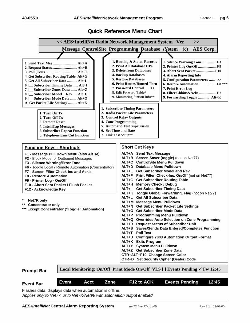
Quick Reference Menu Chart
1. Send Text Msg .......................... Alt+A2. Request Status ........................... Alt+R3. Poll (Test) .................................. Alt+T4. Get Subscriber Routing Table Alt+G5. Get All Subscriber Data ........... Alt+L6. |__ Subscriber Timing Data ...... Alt+I7. |__ Subscriber Zones Data ....... Alt+Z8. |__ Subscriber Model + Rev ..... Alt+E9. |__ Subscriber Mode Data ....... Alt+OA. Get Packet Life Settings .......... Alt+N
Message ControlSite Programming Database sYstem (c) AES Corp.
<< AES•IntelliNet Radio Network Management System Ver >>
Event ____ Acct____ Zone ____ F12 to ACK ____Events Pending 12:45Event BarFlashes data; displays data when automation is offline.Applies only to Net77, or to Net7K/Net99 with automation output enabled
Prompt Bar
Function Keys - ShortcutsF1 - Message Pull Down Menu (also Alt+M)F2 - Block Mode for Outbound MessagesF3 - Silence Warning/Error ToneF6 - Toggle Local / Remote Automation (Concentrator)F7 - Screen Filter Check-Ins and Ack'sF8 - Restore AutomationF9 - Printer Log - On/OffF10 - Abort Sent Packet / Flush PacketF12 - Acknowledge Key
Short Cut KeysALT+A Send Text MessageALT+B Screen Saver (toggle) (not on Net77)ALT+C ControlSite Menu PulldownALT+D Database Menu PulldownALT+E Get Subscriber Model and RevALT+F Print Filter, Check-Ins, On/Off (not on Net77)ALT+G Get Subscriber Routing TableALT+H Memory Check / DebugALT+I Get Subscriber Timing DataALT+K Toggle Global Forwarding, Flag (not on Net77)ALT+L Get All Subscriber DataALT+M Message Menu PulldownALT+N Get Subscriber Packet Life SettingsALT+O Get Subscriber Mode DataALT+P Programming Menu PulldownALT+Q Overrides Auto Selection on Zone ProgrammingALT+R Request Status of Subscriber UnitALT+S Saves/Sends Data Entered/Completes FunctionALT+T Poll TestALT+U Configure 7003 Automation Output FormatALT+X Exits ProgramALT+Y System Menu PulldownALT+Z Get Subscriber Zone DataCTR+ALT+F10 Change Screen ColorCTR+D Set Security Cipher (Dealer) Code
1. Turn On Tx2. Turn Off Tx3. Remote Reset4. IntelliTap Messages5. Subscriber Repeat Function6. Telephone Line Cut Function
1. Silence Warning Tone ............... F32. Printer Log On/Off .................... F93. Abort Sent Packet .................... F104. Alarm Reporting Info5. Configuration Parameters ...... >>6. Restore Automation ................... F8 ***7. Print Error Log8. Filter Chkins&Acks ................... F79. Forwarding Toggle ............ Alt+K
1. Routing & Status Records2. Print All Database ID's3. Delete from Databases4. Backup Databases5. Restore Databases6. Print Routes/Routed Thru7. Password Control . . . >>8. Edit Forward Table*9. Monitoring Station Info**
1. Subscriber Timing Parameters2. Radio Packet Life Parameters3. Control Relay Outputs4. Zone Programming5. Automatic Test Supervision6. Set Time and Date7. Link Test Setup**
* Net7K only** Concentrator only*** Except Concentrator ("Toggle" Automation)
Local Monitoring: On/Off Print Mode On/Off VLS [ ] Events Pending � Fw 12:45

AES•IntelliNet Central Alarm Reporting System net7X / net77-b1.p65 Rev B.1 11/02/00
AES•IntelliNet Network Management Program Section 3 pg 740-0551u
�
<< AES•IntelliNet Radio Network Management System Ver. . >>
Message ControlSite Programming Database sYstem (c) AES Corp.
To Select Entry: Use Cursor Keys + Enter, Type Entry Number, ESC to Exit
EXAMPLE - Select the"Message" function group:The word "Message" on themenu bar has the first letter"M" highlighted in the colorred. This group is selected bypressing the <ALT> key plusthe <M> key. The MessageGroup pulldown menu willnow appear under the word"Message" on the menu bar.
1. Send Text Msg ............................ Alt+A2. Request Status .................................. Alt+R3. Poll (Test) .......................................... Alt+T4. Get Subscriber Routing Table ........ Alt+G5. Get All Subscriber Data .................. Alt+L6. |__ Subscriber Timing Data ............. Alt+I7. |__ Subscriber Zones Data .............. Alt+Z8. |__ Subscriber Model + Rev ............ Alt+E9. |__ Subscriber Mode Data ............... Alt+OA. Get Packet Life Settings .................. Alt+N
The first of the pulldown functions, "Send Text," will be highlighted as shown above. Other functionswithin the pulldowns are selected using the up/down arrow keys. The highlight bar follows the cursor.The pulldown functions are executed when the user presses <ENTER>. Alternately, pulldown functionscan be executed by pressing the line number of the desired function.
Alternate menu bar function pulldowns can be selected by using the left and right arrow keys. Pressingthe <ESC> key will close the pulldown menu and return you to normal communication monitoringmode. Pressing the <ESC> key within a function block also will return you to the normal mode.
NOTE: When a pulldown, or function block pop-up is displayed, incoming network messages are tempo-rarily stored in a buffer. When the buffer is full, or if an important message must be displayed on thescreen, the program automatically returns itself to normal monitoring operation, thereby ensuring that nomessages are missed.
Note also that many of the functions can be accessed directly by "hot key" combinations like"<ALT>+<T>, <ALT>+<A>, etc." Hot key notations appear on the same line as the function descrip-tions. Note the "SHORTCUTS" called out through this manual for the quickest ways of executingcommands.
Access to Program Functions / Shortcuts

AES•IntelliNet Central Alarm Reporting System net7X / net77-b1.p65 Rev B.1 11/02/00
AES•IntelliNet Network Management Program Section 3 pg 840-0551u
Enter Origin ID, orUse arrow keys,PGUP, PGDNto Scroll Thru List.Home Moves to StartEnd Moves to EndHit <ENTER> toComplete Selection
There are 9 IDs
000110022003300440055006600770088009
<< AES•IntelliNet Radio Network Management System Ver. >>
Message ControlSite Programming Database sYstem (c) AES Corp.
To Select Entry: Use Cursor Keys + Enter, Type Entry Number, ESC to Exit
Selecting a Route for Communications with a Subscriber UnitSince each subscriber unit in your AES•IntelliNet system acts as a radio repeater, there are a many routesfor messages to travel from its source to the central station. Each time a message is received from a unit,the software extracts the subscriber unit ID number of the origin, and the ID number of repeaters in themessage's route. That route information is stored in a database and is used whenever an operator sendsdata to a subscriber unit from the central station.
continued >
Using the Picklist Pop Upto Select a SubscriberWhen a function is chosen from afunction group, a "picklist pop-up" appears. You can type in theID number of the subscriber unityou wish to contact, or use thearrow keys to highlight the appro-priate ID number. Press <EN-TER> to select it. (New subscriberunits are automatically added tothe Picklist when a signal isreceived.)
NOTE: The last ID# selectedremains at the top of the list foreasy access.

AES•IntelliNet Central Alarm Reporting System net7X / net77-b1.p65 Rev B.1 11/02/00
AES•IntelliNet Network Management Program Section 3 pg 940-0551u
Press Alt S to Send/Save, Alt E to Erase Route Fields, else ESC to Exit
Select By Pressing Keys 1,2,3 or 4. Otherwise Press ESC Key
1. or <ENTER> Last Route Mon, Mar 06 15:12:12 YYYY
DIRECT
2. Next to Last Route Mon, Mar 06 14:53:24 YYYY
7054
3. Most Frequent Route Mon, Mar 06 15:12:12 YYYY
DIRECT Count = 64
4. or � to Manually Enter Route
Route Thru Other(s)Now Direct to Target
Target
Central
<<Function Title>>
<< AES•IntelliNet Radio Network Management System Ver. >>
Message ControlSite Programming Database sYstem (c) AES Corp.
To Select Entry: Use Cursor Keys + Enter, Type Entry Number, ESC to Exit
<< AES•IntelliNet Radio Network Management System Ver. >>
Message ControlSite Programming Database sYstem (c) AES Corp.
Choosing a Routewith the Routing Pop UpOnce you have selected thesubscriber unit number, the basicrouting pop-up appears (shown).You may communicate with theunit through its most recentroute, through its next mostrecent route, through its mostfrequently-used route, or youmay manually enter a route.
To choose the most recent route of communications, simply press <ENTER> or the number <1>. The"last" route, or most recent route, is the default setting on this pop-up. To select the second most recentroute, press the number <2> on your keyboard. To select the most frequently used route of communica-tion, press the number <3> key.
To manually enter a route to the subscriber unit, press the number <4> key (or the down arrow) and fillout the manual routing screen as instructed below.
Manually Choosing a RouteThe form shown at right allowsyou to manually select a route toa subscriber unit. Use the Back-space key to move the cursorinto the boxes and to erase anyexisting characters.Type the ID number of thestation closest to your centralstation first, then press <EN-TER>. Then enter the nextclosest and hit <ENTER>, etc.You may enter up to eightintermediate subscriber stationsto construct your route.
Once you have entered your communications route, hold down <ALT> and press the <S> key tosend the message to your subscriber unit using the route you entered.
Selecting a Route for Communications, continued

AES•IntelliNet Central Alarm Reporting System net7X / net77-b1.p65 Rev B.1 11/02/00
AES•IntelliNet Network Management Program Section 3 pg 1040-0551u
<< AES•IntelliNet Radio Network Management System Ver. >>
Print Logging is ON/OFF Automation Offline ## Events Pending
A beep sound is also generated, which is acknowledged and silenced using the F12 key.
IMPORTANT: When automation is disconnected, this on-screen display and the printer con-nected to the controller/computer are the only readout devices for all events received by theAES•IntelliNet system. Non-alarm events such as check-ins are also printed to the printer.
When an "alarm", "status", "trouble" or "restoral" message is received during an "AutomationOffline" period, the following procedure is followed:
• The prompt bar at the bottom of the screen turns RED, and details of the event are displayed:
Account #### [Event Type] Zone ## Press F12 to Acknowledge ## Events Pending [time]
• An audible beeper is sounded.• The alarm data is printed on the printer connected to the controller/computer• The operator silences the tone by pushing the F3 key• The operator acknowledges the event by pressing the F12 key• The acknowledgment is printed on the printer connected to the controller/computer• The "Events Pending" counter decrements by 1.• The operator acknowledges one event each time the F12 key is pushed.
To return to normal operating mode, correct the problem that caused a loss of communication withautomation. When the link to automation is reestablished :
• Acknowledge all pending events• Reestablish link to automation by pressing F8 (The Net software-to-receiver link restores automatically when the connection is restored)• Normal operation resumes
Message ControlSite Programming Database sYstem (c) AES Corp.
Manual Mode / Automation Offline -Used on all Net77; Optional on Net7K/Net99 with Automation enabled
For Net77, or Net7K/Net99 systemswith automation enabled: If the link islost between the AES controller/com-puter and the automation software, theAES Net software activates a "manualacknowledge" mode. At the bottom ofthe screen, the prompt bar turns purple,and the message "Automation Offline"bar appears.
Automation Output• Net77 users: Net77 software provides an output to automation from the controller computer. It isalways enabled - move on to next section, Manual Mode/Automation Offline.
• For systems using Net7K and Net99 software, the output to automation is typically provided bythe receiver (7000/1, /2, 7003 or 7099). If you wish, Net7K or Net 99 can provide an output toautomation. To activate this feature, exit the program (Alt-X). At the prompt type:
Net7KP /AON (or Net7KF /AON)
To disable the feature type:Net7KP /AOFF (or Net7KF /AOFF)
To display current settings type:Net7KP /? (or Net7KF /?)
AES•IntelliNet Central Alarm Reporting System net7X / net77-b1.p65 Rev B.1 11/02/00
AES•IntelliNet Network Management Program Section 3 pg 1140-0551u
� 1. Send ASCII......Alt A
<< AES•IntelliNet Radio Network Management System Ver. >>
To Select Entry: Use Cursor Keys + Enter, Type Entry Number, ESC to Exit
�
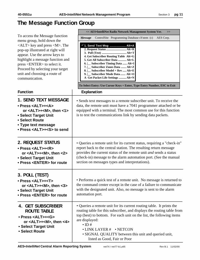
• Sends text messages to a remote subscriber unit. To receive thedata, the remote unit must have a 7041 programmer attached or beequipped with a terminal. The most common use for this functionis to test the communications link by sending data packets.
• Queries a remote unit for its current status, requiring a "check-in"report back to the central station. The resulting return messageprovides the current status of the remote unit and sends a status(check-in) message to the alarm automation port. (See the manualsection on messages types and interpretations).
The Message Function Group
To access the Message functionmenu group, hold down the<ALT> key and press <M>. Thepop-up illustrated at right willappear. Use the arrow keys tohighlight a message function andpress <ENTER> to select it.Proceed by selecting your targetunit and choosing a route ofcommunication.
3. POLL (TEST)• Press <ALT>+<T> or <ALT>+<M>, then <3>• Select Target Unit• Press <ENTER> for route
1. SEND TEXT MESSAGE• Press <ALT>+<A> or <ALT>+<M>, then <1>• Select Target Unit• Select Route• Type text message• Press <ALT>+<S> to send
Function Explanation
2. REQUEST STATUS• Press <ALT>+<R> or <ALT>+<M>, then <2>• Select Target Unit• Press <ENTER> for route
• Performs a quick test of a remote unit. No message is returned tothe command center except in the case of a failure to communicatewith the designated unit. Also, no message is sent to the alarmautomation port.
1. Send Text Msg .................... Alt+A2. Request Status ........................... Alt+R3. Poll (Test) ................................. Alt+T4. Get Subscriber Routing Table Alt+G5. Get All Subscriber Data ........... Alt+L6. |__ Subscriber Timing Data ...... Alt+I7. |__ Subscriber Zones Data ....... Alt+Z8. |__ Subscriber Model + Rev ..... Alt+E9. |__ Subscriber Mode Data ....... Alt+OA Get Packet Life Settings .......... Alt+N
4. GET SUBSCRIBERROUTE TABLE
• Press <ALT>+<G> or <ALT>+<M>, then <4>• Select Target Unit• Select Route
• Queries a remote unit for its current routing table. It prints therouting table for this subscriber, and displays the routing table fromtop (best) to bottom. For each unit on the list, the following itemsare displayed:
• ID #• LINK LAYER # • NETCON• SIGNAL QUALITY between this unit and queried unit,
listed as Good, Fair or Poor
Message ControlSite Programming Database sYstem (c) AES Corp.

AES•IntelliNet Central Alarm Reporting System net7X / net77-b1.p65 Rev B.1 11/02/00
AES•IntelliNet Network Management Program Section 3 pg 1240-0551u
The Message Function Group, continuedFunction Explanation
• Queries a remote unit for its current zone configurations. Thereceived data updates the Zone Configuration database. The ZoneConfiguration is part of the Programming Function Group de-scribed in the following pages.
NOTE: 7050 can be equipped with up to 9 banks of 8 zones each.When queried with this function, un-installed zones show asNormally Open, No Restoral, the default condition.
7. (GET) SUBSCRIBERZONES DATA
• Press <ALT>+<M>, then <7> or Press <ALT>+<Z>• Select Target Unit• Select Route
6. (GET) SUBSCRIBERTIMING DATA
• Press <ALT>+<M>, then <6> or Press <ALT>+<I>• Select Target Unit• Select Route
• Queries a remote unit for its current timing parameters. Thereceived data updates the timing parameters database. Timingparameters are part of the Programming Function Group describedin the following pages.
5. GET ALLSUBSCRIBER DATA
• Press <ALT>+<M>, then <5> or Press <ALT>+<L>• Select Target Unit• Select Route
• Queries a remote unit for ALL of it s currently programmedparameters. The function automatically performs functions 6, 7,8 and 9, retrieving Timing, Zones, Model #/Rev and Mode datafor the unit you specify. (See specifics below).
8. (GET) SUBSCRIBERMODEL & REV
• Press <ALT>+<M>, then <8> or Press <ALT>+<E>• Select Target Unit• Select Route
• Queries a remote unit for its model number (e.g. 7750F, 7450,7050E, etc.) and its firmware revision number. This information isstored in the Net software database.
9. (GET) SUBSCRIBERMODE DATA
• Press <ALT>+<M>, then <9> or Press <ALT>+<O>• Select Target Unit• Select Route
• Queries a remote unit for the current "mode" settings (enable/disable) for 3 different parameters: • IntelliTap Message, default = enabled
(works with 7050-E (Ver 2+), 7750-F, 7450, 7440 only) • Subscriber Repeater Function, default = enabled
(works with all units except 7440, which do not repeat) • Telephone Line Cut Function, default = disabled
(works with 7450, 7440 only)
A. (GET) SUBSCRIBERPACKET LIFE SETTINGS
• Press <ALT>+<M>, then <A> or Press <ALT>+<N>• Select Target Unit• Select Route
• Queries a remote unit for its Packet Life Settings (aka Time-to-Live or TTL). This function can only be used with Version 2+subscribers with TTL capability. Other are not supported. Thisinformation is stored in the Net software database.See also - Radio Packet Life Parameters, Programming Menu.

AES•IntelliNet Central Alarm Reporting System net7X / net77-b1.p65 Rev B.1 11/02/00
AES•IntelliNet Network Management Program Section 3 pg 1340-0551u
� 1. Send ASCII......Alt A
<< AES•IntelliNet Radio Network Management System Ver. . >>
Message ControlSite Programming Database sYstem (c) AES Corp.
The ControlSite Function Group
To Select Entry: Use Cursor Keys + Enter, Type Entry Number, ESC to Exit
1. TURN ON TX
Function Explanation
• Press <ALT> + <C>• Press <1>• Select Target Unit• Select Route
• Re-enables transmitting on a remote subscriber unit that has beenturned off (see Turn Off TX, next).
• Disables a remote subscriber unit should the need arise, such aswhen an alarm system fails and causes the transmitter to activaterepeatedly. NOTE: The unit is not literally turned off, but isprevented from transmitting until it receives the "Turn On" signal(above). Note that a transceiver in the Off Mode will create routefailed message when including in an outbound route.
WARNING: This function disables the subscriber - use it onlywhen absolutely necessary.
• This function may be used on UL Burglar Alarm and Fire Alarmsystems only with strict adherence to the requirements of ULStandard 611, Central Station Burglar Alarm Units and the Na-tional Fire Alarm Code, NFPA 72.
2. TURN OFF TX• Press <ALT> + <C>• Press <2>• Select Target Unit• Select Route
3. REMOTE RESET• Press <ALT> + <C>• Press <3>• Select Target Unit• Select Route
• Resets the remote subscriber unit - the same as physically push-ing the reset button on the unit itself. This causes the subscriberunit to re-enroll on the network and build a new routing table.
A reset may be used to restart the check-in interval timer. The newinterval will commence at the time of reset (see also: subscriberunit manuals).
To access the ControlSite func-tion menu group, hold down the<ALT> key and press <C>. Thepop-up illustrated at right willappear. Use the arrow keys tohighlight a control function andpress <ENTER> to select it.Proceed by selecting your targetunit and choosing a route ofcommunication.
� 1. Turn On TX 2. Turn Off Tx3. Remote Reset4. IntelliTap Messages5. Subscriber Repeat Function6. Telephone Line Cut Function
AES•IntelliNet Central Alarm Reporting System net7X / net77-b1.p65 Rev B.1 11/02/00
AES•IntelliNet Network Management Program Section 3 pg 1440-0551u
� 1. Send ASCII......Alt A
Function Explanation
1. Turn On TX2. Turn Off Tx3. Remote Reset� 4. IntelliTap Messages� 5. Subscriber Repeat Function� 6. Telephone Line Cut Function
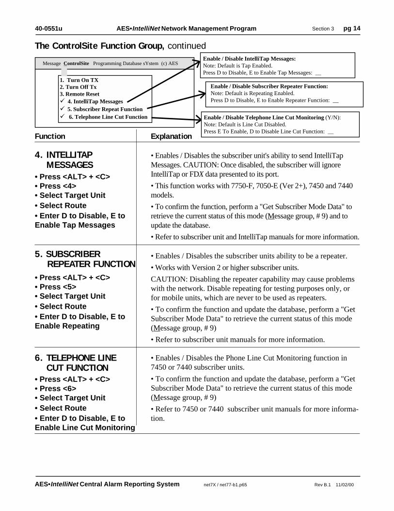
4. INTELLITAPMESSAGES
• Press <ALT> + <C>• Press <4>• Select Target Unit• Select Route• Enter D to Disable, E toEnable Tap Messages
• Enables / Disables the subscriber unit's ability to send IntelliTapMessages. CAUTION: Once disabled, the subscriber will ignoreIntelliTap or FDX data presented to its port.
• This function works with 7750-F, 7050-E (Ver 2+), 7450 and 7440models.
• To confirm the function, perform a "Get Subscriber Mode Data" toretrieve the current status of this mode (Message group, # 9) and toupdate the database.
• Refer to subscriber unit and IntelliTap manuals for more information.
The ControlSite Function Group, continuedEnable / Disable IntelliTap Messages:Note: Default is Tap Enabled.Press D to Disable, E to Enable Tap Messages: __
5. SUBSCRIBERREPEATER FUNCTION
• Press <ALT> + <C>• Press <5>• Select Target Unit• Select Route• Enter D to Disable, E toEnable Repeating
• Enables / Disables the subscriber units ability to be a repeater.
• Works with Version 2 or higher subscriber units.
CAUTION: Disabling the repeater capability may cause problemswith the network. Disable repeating for testing purposes only, orfor mobile units, which are never to be used as repeaters.
• To confirm the function and update the database, perform a "GetSubscriber Mode Data" to retrieve the current status of this mode(Message group, # 9)
• Refer to subscriber unit manuals for more information.
Enable / Disable Subscriber Repeater Function:Note: Default is Repeating Enabled.Press D to Disable, E to Enable Repeater Function: __
Enable / Disable Telephone Line Cut Monitoring (Y/N):Note: Default is Line Cut Disabled.Press E To Enable, D to Disable Line Cut Function: __
6. TELEPHONE LINECUT FUNCTION
• Press <ALT> + <C>• Press <6>• Select Target Unit• Select Route• Enter D to Disable, E toEnable Line Cut Monitoring
• Enables / Disables the Phone Line Cut Monitoring function in7450 or 7440 subscriber units.
• To confirm the function and update the database, perform a "GetSubscriber Mode Data" to retrieve the current status of this mode(Message group, # 9)
• Refer to 7450 or 7440 subscriber unit manuals for more informa-tion.
Message ControlSite Programming Database sYstem (c) AES

AES•IntelliNet Central Alarm Reporting System net7X / net77-b1.p65 Rev B.1 11/02/00
AES•IntelliNet Network Management Program Section 3 pg 1540-0551u
ID # Subscriber Timing Parameters [XX]=Default
Automatic Test Interval [24 Hrs]: 24 (Hrs) 00 (Mins)
Additional Event Report Delay (0 to 80 Sec) [10]: 10
7050/7750-UL Loop Response (.05 to 2.5 Sec) [0.12]: 0.12
Acknowledgment Delay (60 to 300 Sec) [90]: 89
Last Updated On: Wed Oct 18 09:30:23 YYYY
Press ALT-I to Get Update from Unit
Press Alt S to Send/Save, Press Delete to erase Fields, else <ESC> to Exit
The Programming Function Group
To access the Programming func-tion menu group, hold down the<ALT> key and press <P>. Thepop-up illustrated at right willappear. Use the arrow keys tohighlight a function and press<ENTER> to select it. Proceed byselecting your target unit andchoosing a route of communication.
The screen illustrated at right enablesan operator to change the timing param-eters of a subscriber unit from thecentral station. Check-in intervals andthe timing for secondary alarm accumu-lation, debounce delay and communica-tion timeout time limits can be pro-grammed using this screen.
� 1. Send ASCII......Alt A
<< AES•IntelliNet Radio Network Management System Ver. . >>
Message ControlSite Programming Database sYstem (c) AES Corp.
To Select Entry: Use Cursor Keys + Enter, Type Entry Number, ESC to Exit
1. SET TIMING PARAMETERS for REMOTE SUBSCRIBER UNITS• TO BEGIN: PRESS <ALT>+<P>, then 1 -- Select ID and routing. When the above screen appears,press <ALT>+<I> This queries the remote subscriber unit to report all its current timing parameters for yourreview. It also updates the Net software database.
• SET AUTOMATIC TEST INTERVAL (Check-In's): PRESS <ALT>+<P>, then 1 -- Select ID androuting. When the above screen appears, a cursor will be flashing at the check-in interval area. The intervalscan be programmed between one minute and 24 hours (the default setting is at 24 hours). To minimize radioair traffic, an interval of 24 hours is recommended except in high security applications. The ability to changethis timing feature by remote is a key advantage of the two-way AES•IntelliNet system. When you haveentered a check-in time interval, press <ENTER> to move on to the next field. When done, press<ALT>+<S> to send.
Net77 / UL and COMMERCIAL FIRE INSTALLATION REQUIREMENTS: • Check In Interval: Set to required amount according to UL codes -see subscriber manual. • Enable Test Time Supervision: NO
Supervision must be monitored by a UL Listed Automation System. • The maximum allowable interval between check in signals on a UL Burglary Alarm systemwith line security is 5 minutes.Note: Whether operating with a Listed Automation System or in manual mode, a UL Burglar AlarmSystem with line security and a Grade A Central Station Burglar Alarm System requires a missingcheck in signal to be responded to as an alarm condition.
� 1. Subscriber Timing Parameters
2. Radio Packet Life Parameters3. Control Relay Outputs4. Zone Programming . . . >>5. Automatic Test Supervision6. Set Time and Date7. Link Test Setup (concentrator only)

AES•IntelliNet Central Alarm Reporting System net7X / net77-b1.p65 Rev B.1 11/02/00
AES•IntelliNet Network Management Program Section 3 pg 1640-0551u
Programming Function Group / 1. Timing Parameters, continued
• ADDITIONAL EVENT REPORT DELAY: This feature allows a subscriber unit to accumulatealarms, after its initial alarm report, for a programmed time period. When an alarm has occurred at aremote subscriber site, the central receiver is notified immediately. The event report delay allows aremote unit to compile subsequent alarms for a period of time, so that a comprehensive packet of alarmdata is sent to the Net77 system all at once, thereby reducing network air time. The default setting forthis feature is 10 seconds. To change the event report delay, enter the new value and press <ENTER> tomove to the next field. An event report delay of 10 seconds is the maximum time limit allowed forUL Burglar Alarm Systems and Commercial Fire Alarm Systems.
• 7050 & 7750/UL LOOP RESPONSE: Programs a debounce delay for the zone inputs of 7050 and7750/UL subscriber units to prevent input switches or relays from causing nuisance alarms and repeatedreports of the same alarm. The default setting is 0.12 seconds. If you choose to change this setting,simply enter the new value and press <ENTER> to move to the next field. A control unit (panel)output(s) to the 7750 RF subscriber unit shall be programmed to latch in when it triggers a zoneinput on the 7750. For UL & Commercial Fire Systems, contact debounce delay may be not longerthan 0.12 seconds.Note: The loop response in the 7050-E, 7440, 7450 and 7750-F units are preset at 0.12 seconds andcannot be changed.
• ACKNOWLEDGMENT DELAY: If a subscriber unit does not receive an acknowledgment withinthe time parameters set by the Acknowledgment Delay function, it activates an output to annunciate theproblem locally. The next successful communication to the central station will include an Ack Delayfault code. The default setting for this feature is 89 seconds. If you choose to change theACKnowledgment DELAY period, simply type in the new value, hold <ALT> and press <S> to com-plete and send your timing parameter data.For 7750/UL and 7750-F Subscriber Units: A zone of the control panel shall be connected to therelay labeled "ACK DELAY", to monitor the subscriber unit against antenna removal, communicationfailure and to provide a local and remote annunciation of such a fault condition. (Refer to subscribermanuals.)
• LAST UPDATED ON: This feature displays the last time that Timing Parameters were sent to orreceived from the subscriber unit selected. All information of this kind is constantly updated by the Netdatabasing system. If no date appears, or if the date seems to be out of range, the timing parameters havenot been set or downloaded through Net software.
To update the database with current Timing information, press <ALT> and <I> to access the "GetData" functions.
NOTE: For all remote program functions, watch to make sure that a data confirmation packet isreceived from the target subscriber (watch scrolling message screen area).

AES•IntelliNet Central Alarm Reporting System net7X / net77-b1.p65 Rev B.1 11/02/00
AES•IntelliNet Network Management Program Section 3 pg 1740-0551u
ID # Packet Life Parameters [XX]=Default
Check in Packet Life: __30 [30 Min Timeout]Status Packet Life: ___0 [0 = No Timeout]Alarm Packet Life: ___0 [0 = No Timeout]Trouble Packet Life: ___0 [0 = No Timeout]Restoral Packet Life: ___0 [0 = No Timeout]IntelliTap Packet Life: ___0 [0 = No Timeout]Specials Packet Life: ___0 [0 = No Timeout]
Note: Packet Timeout Times Range from 10 to 1440 Minutes.A Value of 0 Minutes = No Timeout of Packet
Press Alt-N to Get Current Packet Lives from ####
Press Alt S to Send/Save, Press Delete to erase Field, else <ESC> to Exit
� 1. Send ASCII......Alt A
<< AES•IntelliNet Radio Network Management System Ver. . >>
Message ControlSite Programming Database sYstem (c) AES Corp.
1. Subscriber Timing Parameters
� 2. Radio Packet Life Parameters
3. Control Relay Outputs4. Zone Programming . . . >>5. Automatic Test Supervision6. Set Time and Date7. Link Test Setup (concentrator only)
2. RADIO PACKET LIFEPARAMETERSTTL/Time-to-Live
Version 2 subscribers include the new“Time-To-Live” or “TTL” function.
Like the Internet, AES-IntelliNet is apacket-based technology. The Time-to-Liveconcept in the Internet is based on the factthat all data has a useful life.
The benefits of TTL are best exhibitedwhen the central station receiver goes offline due to a lightning hit or some otherunlikely, catastrophic event. While the receiver isoff line, messages traveling through the system arestored in the individual subscriber units for laterdelivery. Under the default TTL settings, unimpor-tant test timer messages (typically 95+% of thetraffic) are deleted from the subscriber unit memoryafter 30 minutes of being delayed in the network.Thus, the system will not have to handle themessage when the central receiver comesback on line. All other messages, such asalarms, etc. speed there way to the centralstation as they normally do.
• Note that even when a check-in packet is deleted due to a delay, the objective of that message has already servedits purpose: the late or missing signal has been flagged at the central station (see Automatic Test Supervisionsection).
• Under the default (factory) settings, only test timer messages are subject to the TTL function. If you want TTLfor other message types, YOU must activate it when you program the subscriber unit.
• The TTL time is included in packets generated by TTL (Ver 2+) subscribers. The timeout function works whena packet is stored for forwarding in any subscriber with TTL (Ver 2+) capability, which will decrement the TTLtime for any packet it is storing. When TTL time has expired, the packet is aborted. This function does not workwith non-TTL (pre-Ver 2) subscribers.
• The TTL feature works best when the majority of subscribers, or the subscribers that are most heavily used,have the feature in the firmware. Call your AES representative for upgrade information.
Default time for Check-In Packets is 00 hours, 30 minutes. DO NOT enter a greater than 24 hrs 00 mins.Entering a time of 00 hours and 00 minutes deactivates the time-to-live function for that packet type.The shortest allowed TTL time is 00 hours, 10 minutes.TTL can also be set for other packet types:
• Status Packets • Alarm Packets • Trouble / Trouble-Restoral Packets
• Zone Restoral Packets • AES-IntelliTAP Packets • Special Packets (Vending, etc.)
The default time for the 6 packet types above is 00, i.e. the time-to-live function is deactivated for these packets.Entering anything greater than 00 HRS and 10 MINS will enable the Time-to-Live function.
Enter the data for each type, press <ALT>+<S> to send.
To confirm the data, press <ALT>+<N> to query the subscriber. When the TTL parameters packet has beenreceived back, check this screen again.
See also - Get Packet Life Settings, Message Functions Group
To Select Entry: Use Cursor Keys + Enter, Type Entry Number, ESC to Exit
Programming Function Group, continued

AES•IntelliNet Central Alarm Reporting System net7X / net77-b1.p65 Rev B.1 11/02/00
AES•IntelliNet Network Management Program Section 3 pg 1840-0551u
Message ControlSite Programming Database sYstem (c) AES Corp.
To Select Entry: Use Cursor Keys + Enter, Type Entry Number, ESC to Exit
<< AES•IntelliNet Radio Network Management System Ver. . >>
Each relay can be individually addressed from the central station. Access the above screen by highlight-ing the "Control Relay Outputs" function on the Programming menu and press <ENTER>, or by pullingdown the Programming menu as shown above and pressing the number <2> key. A control form ap-pears.
• USING THE CONTROL RELAY OUTPUT BLOCK - Using the arrow keys, place the cursor on thebox representing the relay you wish to activate or deactivate. To activate a relay, press the <+> key. Todeactivate a relay, press the <-> key. To toggle a relay, press the <T> key. Boxes with no data enteredare set to OFF mode, the default setting. Move through the control relay output boxes by using thearrow keys. To send the command and save it in the database, hold down the <ALT> key and press the<S> key. The relays are latching (except as noted below); when a function has been turned on, a sepa-rate command must be sent to turn it off.
NOTES:• For pre-version 2 model 7050 units, the toggle function may cause the relay to toggle multiple timesbecause multiple receptions may occur. The final state cannot be predicted. It is not recommended.• For Version 2 and new model 7050 units, the toggle function is a Momentary - i.e. the relay will pullin for approximately 1 second, then release.
3. CONTROL RELAY OUTPUT
This feature controls optional relayoutputs (part number 7065) formodel 7050 subscriber units. Usingthis remote control capability, anoperator may open gates, activatecameras or control any device at aremote location. The basic relayoutput uses eight relays, but asmany as 64 may be controlled. Thisfeature has not been evaluated forUL Listing.
01 02 03 04 05 06 07 08 09 10 11 12 13 14 15 16
17 18 19 20 21 22 23 24 25 26 27 28 29 30 31 32
33 34 35 36 37 38 39 40 41 42 43 44 45 46 47 48
49 50 51 52 53 54 55 56 57 58 59 60 61 62 63 64
�������������������������������
�������������������������������
�������������������������������
�������������������������������
ID # Control Relay OutputsFunction Keys
<+> <-> <T> Depends on Ver =ON =OFF =Toggle or Mom
Using the control block illustrated atright, the operator can turn on, turnoff or toggle any switch connected tothe subscriber unit relay board fromthe central station. Each box repre-sents a relay.
If a box is left blank, the "OFF"command (default) will be sent.
1. Subscriber Timing Parameters2. Radio Packet Life Parameters
� 3. Control Relay Outputs
4. Zone Programming . . . >>5. Automatic Test Supervision6. Set Time and Date7. Link Test Setup (concentrator only)
Programming Function Group, continued

AES•IntelliNet Central Alarm Reporting System net7X / net77-b1.p65 Rev B.1 11/02/00
AES•IntelliNet Network Management Program Section 3 pg 1940-0551u
Note: Set Timing Parameters First.This function configures alarm zoneinputs at a remote unit. It is important toknow which type of unit is beingprogrammed. There are five separatesub-menus to handle the different sub-scriber units, including: • 7050/7750-UL • 7050-E (pre-version 1.9) • 7050-E (version 2.0+) • 7450 / 7440 .
• 7750-FUse the cursor to select "Zone Programming" or type <ALT>+<P>, then <4>. Select the subscriber unit# from the pick list. If the unit already has zone information stored in the database, the function auto-matically goes to the correct sub-menu. Those submenus are listed in the following pages.If the target unit is not in the database, a menu pops up:
Unknown Subscriber Type. Download Data from Subscriber.To Override. Enter: 1. 7050/7750-UL, 2. 7050E, 3. 7050E Rev 2.0+ 4. 7450, 5. 7750F:
It is recommended that you enter <ALT>+<L> to perform a "Get-All" data from this subscriber, includ-ing it's type. The retrieved data is stored in the database for future reference. (See more details under theMessage Group pulldown.) Wait a few moments while the subscriber unit responds, then retry the ZoneProgramming function.Or, you can skip the "Get Data" function if you are certain of the unit type and revision. Enter a digit 1 to5 the for the type of unit listed on the screen pop-up.CAUTION: Sending zone programming data to the wrong type of subscriber may cause unpredictableresults.Another warning screen pops up to remind you to be certain of which type of unit is being programmed:
Warning! No Trouble Signals* unless Central Firmware 1.70+First put [unit #] on Test Before Programming.The Remote Programming of Zones Can be DangerousCorrect Wiring, and Subscriber Model can be unknown.Changing Programming can create New Alarms.Use at your own risk.
Note: Always Reset Subscriber after Zone Programming.This is to Prevent Zone Conflicts.Type Any Key to Continue.
* If you program the subscriber zones to report "trouble" (such as in "Fire" zone mode), the troublemessages can only be received by a version 1.70 or newer receiver. (This is the version of the chip in thereceiver- not the software you are using here.) Upgrades are available, contact AES for details.
4. ZONE PROGRAMMINGfor Subscriber Units
To Select Entry: Use Cursor Keys + Enter, Type Entry Number, ESC to Exit
<< AES•IntelliNet Radio Network Management System Ver. . >>
Message ControlSite Programming Database sYstem (c) AES Corp.
1. Subscriber Timing Parameters2. Radio Packet Life Parameters3. Control Relay Outputs
� 4. Zone Programming
5. Automatic Test Supervision6. Set Time and Date7. Link Test Setup (concentrator only)
Programming Function Group, continued

AES•IntelliNet Central Alarm Reporting System net7X / net77-b1.p65 Rev B.1 11/02/00
AES•IntelliNet Network Management Program Section 3 pg 2040-0551u
The zone configuration control blockoffers five options for the program-ming of each alarm zone. The under-lined letters below designate the stateof the circuit.1. Normally Open2. Normally Open + Restoral3. Normally Closed4. Normally Closed + Restoral5. Bypassed6. Supervised7. Supervised + Restoral
• USING THE ZONE CONFIGURATION CONTROL BLOCK: Use the arrow keys to place thecursor on the box of the zone you wish to program. Each zone has two sections. The left side of the boxindicates the normal state of the circuit (Open, Closed, Supervised or Bypassed). The right side of thebox indicates the Restoral setting. If you would like the subscriber unit to communicate a Restoral afteran event, type an "R" in the right side. UL and NFPA require all zones of the 7750/UL Subscriber Unitto be programmed for Restoral signals. However, the control unit outputs to the 7750/UL unit mustlatch until manually reset. To make no change in a zone, simply pass over the filled in box using thearrows on your keyboard. To send and save the zone configuration command, hold down the <ALT> and<S> keys. Zones that are not programmed will return to a default setting of Normally Open.
UL and COMMERCIAL FIRE INSTALLATION REQUIREMENTS for 7750/UL SubscriberUnits:
• Zones 1-6: Bypassed• Zone 7: N.O. w/Restoral - Tamper (creates a N.C. loop through zone 7 of 7072 module)• Zone 8: N.O. w/Restoral - AC Fail (from 7072 multi-board)• Zones 9-24, depending on the output of the control unit:
Normally open with Restoral, or Normally Closed with Restoral, orSupervised with Restoral, or if zone not used, Bypass
Next, perform a reset (press <ALT>+<C>, then 3, then select the unit from the pick list and choose aroute.To verify the information actually stored by the subscriber unit, press <ALT>+<Z>. This downloads thedata from the subscriber unit into the "Net" software database. (Upper zones not installed will show adefault "O").
01 02 03 04 05 06 07 08
09 10 11 12 13 14 15 16 17 18 19 20 21 22 23 24
25 26 27 28 29 30 31 32 33 34 35 36 37 38 39 40
41 42 43 44 45 46 47 48 49 50 51 52 53 54 55 56
57 58 59 60 61 62 63 64 65 66 67 68 69 70 71 72
-- Zones 1 thru 8--N O_, N C_ + Restorals
-- Zones 9 thru 72 --Also Supervised S _ , S RAny Zone Bypassed B_
ID # Zone Configuration <ALT> S When Done <ALT>Z To Update
���������������
�������������������������������
�������������������������������
�������������������������������
�������������������������������
ZONE PROGRAMMING for 7750/UL & 7050 SubscribersRefer to 7750/UL or 7050 Subscriber Unit Manual for details on zone wiring and programming.
This screen appears if the unit zone information is in the database, or if you selected 1 from the "Over-ride" box choices (see preceding page).Up to 72 separate zones on each remote subscriber unit can be addressed from the central station. Com-plete the Zone Configuration control block as instructed below.
Programming Function Group, Zone Programming, continued

AES•IntelliNet Central Alarm Reporting System net7X / net77-b1.p65 Rev B.1 11/02/00
AES•IntelliNet Network Management Program Section 3 pg 2140-0551u
The zone configuration control block offersfive options for the programming of eachalarm zone. The underlined letters belowdesignate the state of the circuit.1. Normally Open2. Normally Open + Restoral3. Normally Closed4. Normally Closed + Restoral5. Bypassed6. Supervised7. Supervised + RestoralNOTE: The Fire and Inverted Fire optionsare not available on Pre-Version 2.0subscriber units.
ALT-Z to Get/Download Current Zone Info.ALT-S to Save/Send When Done.Note: Red Character Means N/A
•USING THE ZONE CONFIGURATION CONTROL BLOCK: Use the arrow keys to place thecursor on the box of the zone you wish to program. Each zone has two sections. The left side of the boxindicates the normal state of the circuit (Open, Closed, Supervised or Bypassed). The right side of thebox indicates the Restoral setting. If you would like the subscriber unit to communicate a Restoral afteran event, type an "R" in the right side. To make no change in a zone, simply pass over the filled in boxusing the arrows on your keyboard. To send and save the zone configuration command, hold down the<ALT> and <S> keys. Zones that are not programmed will return to a default setting of Normally Open.To verify the information actually stored by the subscriber unit, press <ALT>+<Z> This downloads thedata from the subscriber unit into the "Net" database.
Programming Function Group, Zone Programming, continued
ZONE PROGRAMMING for Pre-Version 2.0 7050-E Subscriber Units
Refer to 7050-E Subscriber Unit Manual for details on zone wiring and programming.
This screen appears if the unit zone information is in the database, or if you selected 1 from the "Over-ride" box choices (see page 19).
Unit [ID #] 7050E Zone ConfigurationFire: Disabled, Inverted Fire, DisabledPress "B" to Bypass any ZoneAdd an "R" for Zone RestoralsPress "O" Norm Open, "C" Norm ClosedPress "F" for Fire, "I" for Inverted FirePress "S" for Supervision (No Troubles) Alarms
01 02 03 04 05 06 07 08�� ���������� ����

AES•IntelliNet Central Alarm Reporting System net7X / net77-b1.p65 Rev B.1 11/02/00
AES•IntelliNet Network Management Program Section 3 pg 2240-0551u
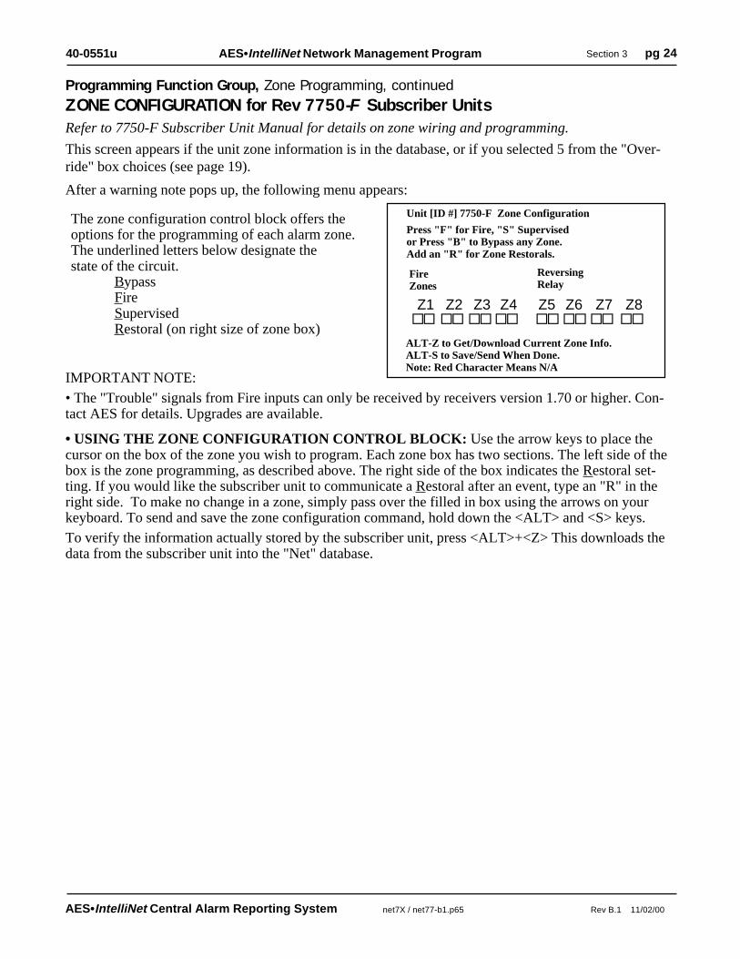
The zone configuration control block offers theoptions for the programming of each alarm zone.The underlined letters below designate thestate of the circuit.
BypassNormally OpenNormally ClosedFireInverted FireSupervisedRestoral (on right size of zone box)
NOTE: The Fire and Inverted Fire options are not available on Pre-Version 2.0 subscriber units.
ALT-Z to Get/Download Current Zone Info.ALT-S to Save/Send When Done.Note: Red Character Means N/A
•USING THE ZONE CONFIGURATION CONTROL BLOCK: Use the arrow keys to place the cursoron the box of the zone you wish to program. Each zone has two sections. The left side of the box indicates thenormal state of the circuit (Open, Closed, Supervised, Fire, Inverted Fire or Bypassed). The right side of thebox indicates the Restoral setting. If you would like the subscriber unit to communicate a Restoral after anevent, type an "R" in the right side. To make no change in a zone, simply pass over the filled in box using thearrows on your keyboard. To send and save the zone configuration command, hold down the <ALT> and <S>keys. Zones that are not programmed will return to a default setting of Normally Open.
To verify the information actually stored by the subscriber unit, press <ALT>+<Z> This downloads the datafrom the subscriber unit into the "Net" database.
Programming Function Group, Zone Programming, continued
ZONE CONFIGURATION for Version 2.0+ 7050-E Subscriber Units
01 02 03 04 05 06 07 08
Refer to 7050-E Subscriber Unit Manual for details on zone wiring and programming.
These screens appear if the unit zone information is in the database, or if you selected 3 from the "Override"box choices (see page 19). The following questions appear:
Will You be using Fire Zones Y/N? Currently (N):__
The programming sequence first asks if any "Fire" inputs are used (refer to subscriber manual). Answer Y/yesif you wish to use the "Fire" configuration, which includes reporting of "Trouble" conditions. Otherwiseanswer N/no. The default or current programming is shown in (_). If you wish to change the setting, enter Yor N. To leave unchanged, simply push ENTER. Next appears:
Will You be using Inverted Fire Zones Y/N? Currently (N): __
Here you can choose to reverse the logic for the fire input (refer to subscriber manual). The current program-ming is displayed. To change the setting enter Y or N. To leave unchanged, push ENTER.
IMPORTANT NOTES:
• The zone programming options are limited. Of the 3 EOL zone types - Supervised, Fire and Inverted Fire,you can choose any 2 for an individual subscriber unit. You can always choose Bypass and Restoral .
• The "Trouble" signals from Fire inputs can only be received by receivers version 1.70 or higher. ContactAES for details. Upgrades are available.
Next appears the zone configuration box:
Unit [ID #] 7050E Zone ConfigurationFire: Disabled, Inverted Fire, DisabledPress "B" to Bypass any ZoneAdd an "R" for Zone RestoralsPress "O" Norm Open, "C" Norm ClosedPress "F" for Fire, "I" for Inverted FirePress "S" for Supervision (No Troubles) Alarms
�� �������� �� ����

AES•IntelliNet Central Alarm Reporting System net7X / net77-b1.p65 Rev B.1 11/02/00
AES•IntelliNet Network Management Program Section 3 pg 2340-0551u
Programming Function Group, Zone Programming, continued
ZONE CONFIGURATION for Rev 7450 & 7440 Subscriber Units
The zone configuration control block offers theoptions for the programming of each alarm zone.The underlined letters below designate thestate of the circuit.
BypassNormally OpenNormally ClosedFireInverted FireSupervisedRestoral (on right size of zone box)
ALT-Z to Get/Download Current Zone Info.ALT-S to Save/Send When Done.Note: Red Character Means N/A
•USING THE ZONE CONFIGURATION CONTROL BLOCK: Use the arrow keys to place thecursor on the box of the zone you wish to program. Each zone has two sections. The left side of the boxindicates the normal state of the circuit (Open, Closed, Supervised, Fire, Inverted Fire or Bypassed). Theright side of the box indicates the Restoral setting. If you would like the subscriber unit to communicatea Restoral after an event, type an "R" in the right side. To make no change in a zone, simply pass overthe filled in box using the arrows on your keyboard. To send and save the zone configuration command,hold down the <ALT> and <S> keys. Zones that are not programmed will return to a default setting ofNormally Open.To verify the information actually stored by the subscriber unit, press <ALT>+<Z> This downloads thedata from the subscriber unit into the "Net" database.
Z1 Z2 Z3 Z4
Refer to Subscriber Unit Manual for details on zone wiring and programming.These screens appear if the unit zone information is in the database, or if you selected 4 from the "Override"box choices (see page 19). The following questions appear:
Will You be using Fire Zones Y/N? Currently (N):__The programming sequence first asks if any "Fire" inputs are used. Answer Y/yes if you wish to have the zonereport "Trouble" conditions. Otherwise answer N/no. The default or current programming is shown in (_). Ifyou wish to change the setting, enter Y or N. To leave unchanged, simply push ENTER. Next appears:
Will You be using Inverted Fire Zones Y/N? Currently (N): __Here you can choose to reverse the logic for the fire input (refer to subscriber manual). The current program-ming is displayed. To change the setting enter Y or N. To leave unchanged, push ENTER.IMPORTANT NOTES:• The zone programming options are limited. Of the 3 EOL zone types - Supervised, Fire and Inverted Fire,you can choose any 2. (You can always choose Bypass and Restoral for any zone.)• The "Trouble" signals from Fire inputs can only be received by receivers version 1.70 or higher. ContactAES for details. Upgrades are available.Next appears the zone configuration box, which displays the available options in :
Unit [ID #] 7450(40) Zone ConfigurationFire: Disabled, Inverted Fire: DisabledPress "B" to Bypass any ZoneAdd an "R" for Zone RestoralsPress "O" Norm Open, "C" Norm ClosedPress "F" for Fire, "I" for Inverted FirePress "S" for Supervision (No Troubles) Alarms
�� ������
AES•IntelliNet Central Alarm Reporting System net7X / net77-b1.p65 Rev B.1 11/02/00
AES•IntelliNet Network Management Program Section 3 pg 2440-0551u
• USING THE ZONE CONFIGURATION CONTROL BLOCK: Use the arrow keys to place thecursor on the box of the zone you wish to program. Each zone box has two sections. The left side of thebox is the zone programming, as described above. The right side of the box indicates the Restoral set-ting. If you would like the subscriber unit to communicate a Restoral after an event, type an "R" in theright side. To make no change in a zone, simply pass over the filled in box using the arrows on yourkeyboard. To send and save the zone configuration command, hold down the <ALT> and <S> keys.To verify the information actually stored by the subscriber unit, press <ALT>+<Z> This downloads thedata from the subscriber unit into the "Net" database.
The zone configuration control block offers theoptions for the programming of each alarm zone.The underlined letters below designate thestate of the circuit.
BypassFireSupervisedRestoral (on right size of zone box)
ALT-Z to Get/Download Current Zone Info.ALT-S to Save/Send When Done.Note: Red Character Means N/A
Z1 Z2 Z3 Z4 Z5 Z6 Z7 Z8
Refer to 7750-F Subscriber Unit Manual for details on zone wiring and programming.
This screen appears if the unit zone information is in the database, or if you selected 5 from the "Over-ride" box choices (see page 19).
After a warning note pops up, the following menu appears:
Unit [ID #] 7750-F Zone Configuration
Press "F" for Fire, "S" Supervisedor Press "B" to Bypass any Zone.Add an "R" for Zone Restorals.
�� ������ ������ ��
FireZones
ReversingRelay
IMPORTANT NOTE:• The "Trouble" signals from Fire inputs can only be received by receivers version 1.70 or higher. Con-tact AES for details. Upgrades are available.
Programming Function Group, Zone Programming, continued
ZONE CONFIGURATION for Rev 7750-F Subscriber Units

AES•IntelliNet Central Alarm Reporting System net7X / net77-b1.p65 Rev B.1 11/02/00
AES•IntelliNet Network Management Program Section 3 pg 2540-0551u
This feature updates the controllercomputer's internal clock. To access theSet Date and Time function, highlightthe Programming menu and use thearrow keys to select the Set Time andDate, then <ENTER>.Or, press <ALT>+<P>, then 6, then<ENTER>.Complete the block as shown.Press <ALT>+<S> when done.
SET SYSTEM TIME AND DATE
AUTOMATIC TESTTIME SUPERVISIONThis feature enables the Net software tomonitor test timer check-ins. When enabled,it alerts an operator if a subscriber unit failsto report in at its scheduled time as pro-grammed in the Subscriber Timing Param-eters function. A missed check-in is reportedas a "T906" trouble signal to automation (seedocument on alarm codes).To access the function, highlight the Pro-gramming menu and use the arrow keys to select the Automatic Test Supervision on the Programmingpulldown, then <ENTER>.Or, press <ALT>+<P>, then 5, then <ENTER>. Select the Unit to be supervised. The following menu ap-pears:
Automatic Test Supervision for [Unit ID#] is On/Off. Turn it On/Off?Y/N: __ else ESC to Exit without Change.
Answer the query by entering Y/yes or N/no.IMPORTANT NOTE: This applies only to Net software with the automation output enabled. The defaultsetting for this feature is "N" for no. If you would like to enable the test time supervision feature, change thesetting to "Y" for yes and press <ENTER> to move to the next field.NOTE: Enabling supervision function BLOCKS check-in signals from being sent to automation.
NET77 / UL and COMMERCIAL FIRE INSTALLATION REQUIREMENTS: • Enable Test Time Supervision: NO Supervision Must be monitored by UL Listed Automation Software. • When operating in Manual Mode, missing check in signals must be responded to as alarms.
To Select Entry: Use Cursor Keys + Enter, Type Entry Number, ESC to Exit
<< AES•IntelliNet Radio Network Management System Ver. . >>
Message ControlSite Programming Database sYstem (c) AES Corp.
1. Subscriber Timing Parameters2. Radio Packet Life Parameters3. Control Relay Outputs4. Zone Programming . . . .
� 5. Automatic Test Supervision
6. Set Time and Date7. Link Test Timer **
1. Subscriber Timing Parameters2. Radio Packet Life Parameters3. Control Relay Outputs4. Zone Programming . . . >>5. Test Time Supervision
� 6. Set Time and Date
7. Link Test Timer **
Programming Function Group, continued
To Select Entry: Use Cursor Keys + Enter, Type Entry Number, ESC to Exit
<< AES•IntelliNet Radio Network Management System Ver. . >>
Message ControlSite Programming Database sYstem (c) AES Corp.
System Date and TimeENTER TIME: [ ] Hours [ ] Minutes [ ] SecondsENTER DATE: [ ] Day [ ] Month [ ] Year

AES•IntelliNet Central Alarm Reporting System net7X / net77-b1.p65 Rev B.1 11/02/00
AES•IntelliNet Network Management Program Section 3 pg 2640-0551u
To access the Database function group,hold down the <ALT> key and press<D>. The pop-up screen illustrated atright will appear. Use the directionalarrows on your keyboard to highlightyour choice and then press <ENTER>or press the line number.
<< AES•IntelliNet Radio Network Management System Ver. >>
1. Routing & Status Records2. Print All Database ID's3. Delete from Databases4. Backup Databases5. Restore Databases6. Print Routes/Routed Through7. Password Control8. Edit Radio Forward Table
NOTE: The AES•IntelliNet database automatically stores routing data on all subscriber units registeredin the system. The data is stored on the computer hard drive in the subdirectory c:\aes\db. The Databasefunction group allows the computer to retrieve information on specific subscriber units and to performbasic data "housekeeping".
• Displays the routing records of any given subscriber unit andthe current status of the subscriber unit, including NETCONrating.Routing records are automatically updated by the program.Routes shown are "outbound", i.e. ID#1 is closest to the central.
1. ROUTING & STATUSRECORDS
• Press <ALT>+<D>• Press <1>• Select Target Unit
To Select Entry: Use Cursor Keys + Enter, Type Entry Number, ESC to Exit
Message ControlSite Programming Database sYstem (c) AES Corp.
Certain UL Burglar Alarm Systems and Commercial FireAlarm Systems requiring a minimum of 2 paths. Multiplepaths can be proven using the Print Routes / Routed Throughfunction.
Note: A NETCON of 5 or less ensures that at least 2 paths areopen to the central station. A NETCON of 6 or more may alsohave multiple paths - use the Print Routes/ Routed Throughfunctions to show this.
Function Explanation
The DatabaseFunction Group
Route Record on 1234ID1 ID2 ID3 ID4 ID5 ID6 ID7 ID8 Date/Time Freq- - - -DIRECT- - - - Tues Sep 08 14:53 1998 Last- - - -DIRECT- - - - Tues Sep 08 14:53 1998 Next
Most Frequent Route- - - -DIRECT- - - - Tues Sep 08 14:53 1998 18241800 Wed Aug 19 02:00 1998 137003 Tue Sep 01 08:40 1998 10
<< Latest Status and Last Known Position >>ID Number: 1234 Link Layer: 1, VLS Time: UnknownNetCon: 0 Fault Code: No Fault Detected, Latitude UnknownLast Received on: Tue Sep 08 14:55:33 1998, Longitude Unknown

AES•IntelliNet Central Alarm Reporting System net7X / net77-b1.p65 Rev B.1 11/02/00
AES•IntelliNet Network Management Program Section 3 pg 2740-0551u
6. PRINT ROUTES /ROUTED THROUGH
• Hold <ALT> + <D>• Press <6>
• Restores a database previously backed up using the BACKUPfunction above. CAUTION: Restoral function overwrites anydatabase file existing on the hard drive. NOTE: While theNet77 is backing up its database, all communications aretemporarily stored in a buffer.UL Note: Use this function only under extreme emergencyconditions and, if possible, only on one receiving system at atime to allow alternate unit to receive and process signals.
5. RESTOREDATABASE
• Hold <ALT> + <D>• Press <5>
• Prints all the ID numbers in the current database. This list isthe same as the ID number "Pop-up" pick list. Have the printerready with plenty of paper. (Press <ESC> to abort printing.)
• Prints out all routes used by a subscriber unit.• Also, a list of units that are "routed through" a given unit can begenerated. This is important for demonstrating that a unit hasmultiple paths available.Certain UL Burglar Alarm Systems and Commercial FireAlarm Systems requiring a minimum of 2 paths, a NETCON of5 ensures that at least 2 paths of communication are open to thecentral station. Or, multiple paths can be proven using thePrint Routes / Routed Through function.
Note: Be sure that the printer is on. Have the printer ready withplenty of paper. (Press <ESC> to abort printing.)
• Deletes the current records of any given subscriber unit.Should that unit check in at a later date, it will be automaticallyentered into the routing database.NOTE: All specific programming information stored in thedatabase for the deleted unit will revert to default settings if thedeleted unit checks in again.
• Backs up the current Net77 database on a floppy disk in drive A.NOTE: While the program is backing up its database, allcommunicatio ns are temporarily stored in a buffer.UL Note: Database backup may only be done during "Open Periods"and only on one alternate receiving systems at a time, so that there willbe no loss or delay in receiving and processing alarm signals.
4. BACKUP DATABASES• Hold <ALT> + <D>• Press <4>• Insert disk in drive A• Press <ENTER>
3. DELETE FROMDATABASES
• Hold <ALT> + <D>• Press <3>• Select Target Unit
2. PRINT ALLDATABASE ID'S
• Press <ALT> + <D>• Press <2>
Database Function Group, continued

AES•IntelliNet Central Alarm Reporting System net7X / net77-b1.p65 Rev B.1 11/02/00
AES•IntelliNet Network Management Program Section 3 pg 2840-0551u
7. PASSWORDCONTROL
• Hold <ALT> + <D>• Press <7>
• Enables the Password Protection function. IMPORTANT:Once this function is enabled, starting or exiting the pro-gram will require a password. Carefully note thepassword(s) used. The password function can be disabled bydeleting the existing passwords
1. Add a New Password • To add a new pass-word enter a 1-3 charac-ter ID code, and then an1-8 character password.Type the passwordagain to assure its accuracy. This function in NOT case sensitive.
1. Add2. Change3. Delete
<< Add a New Password >>
ID: [ ] Password: [ ]
Confirm: [ ]
2. Change a Password • To change a passwordenter the 3 character IDcode that you wish tochange. Enter the oldpassword, and then typethe new password.
<< Change Password >>
ID: [ ] Old Pwd: [ ]
New Pwd: [ ]
3. Delete a Password • To delete a passwordenter the 3 character IDcode that you wish todelete. Enter the oldpassword, and then typeY to confirm.
<< Delete Password >>
ID: [ ] Old Pwd: [ ]
To Confirm Delete: [ ] Type (Y)es
Database Function Group, continued

AES•IntelliNet Central Alarm Reporting System net7X / net77-b1.p65 Rev B.1 11/02/00
AES•IntelliNet Network Management Program Section 3 pg 2940-0551u
8. EDIT RADIOFORWARD TABLE
• Hold <ALT> + <D>• Press <8>
• Select the ID for the unit whose data will be forwarded.
Send [Unit ID] Message to : [ ]
<< Edit Forward Table >>Origin ID : Unit # Forward to : Unit #
Memo : Address etc.
___________________________________
Forward Filter Flags: Type Y/N
ALARM: [ ] -> Zones : #1 #2 #3 #4 #5 #6 #7 #8
[ ] [ ] [ ] [ ] [ ] [ ] [ ] [ ]
Z REST: [ ] -> Zones : #1 #2 #3 #4 #5 #6 #7 #8
[ ] [ ] [ ] [ ] [ ] [ ] [ ] [ ]
STAT: [ ] CHKIN: [ ] DATA: [ ] HPBU: [ ]
Relay Following: [ ]
TEST: [ ] ZDATA: [ ] VLS: [ ] TEXT: [ ]
Alarm Automation Message: [ ]
Database Function Group, continued
Limits and Availability:
• This function is limited to 3 unitsin the Net7K and Net99 software. Itis not available on Net77 software.
• Net7KF software offers unlimitedforwarding.
• Forwarding increases air traffic onthe network, which may lead toslowdowns on busy systems. Useforwarding only when required.Forward only essential data.
• There is no guarantee the for-warded data will be received; theremote site that receives the data is not a substitute for a central receiver.
• Net software must be running for this function to perform.
AES Net software can forward the activity data of a subscriber unit to another subscriber unit. The datais sent to the RS-232 port of the receiving unit, where a handheld programmer (terminal), a printer or acomputer may be connected. This allows a secondary site to monitor alarms, restorals check-ins, etc. at asecondary location. This function is for secondary reporting only - the central receiver is always theprimary monitoring site.
• Enter Origin ID, and then the ID of the unit data is to be forwarded to.
• Add a memo (such as name/address) of up to 40 characters. This memo is sent with all forwarded data.
• Enter <Y> for each type of data that you want forwarded. You can forward the following data types:
Zone Alarms and Restorals; Status; Check-Ins; Data; HPBU / Programming Uploads; Test; ZoneData; VLS/Vehicle Location Data; Text Messages.
Other Options
Alarm Automation Message: Alarm activity can be transmitted to the remote unit in Alarm Automa-tion Format. The RS-232 output of a special "FA" or "FAA" 7050 receiving unit can feed alarm datadirectly to a computer running automation software.
Relay Following: This special functions requires a 7050 subscriber unit with a 7065 Relay Output boardinstalled. When a zone in alarm message is received from the origin unit, a relay on the forward-to unitwill be activated. If zone goes into alarm on the origin unit, the message is received at the central station.When programmed for forwarding with relay following, a relay control command is sent to the receivingunit (which must be a 7050 unit with 7065 relay board). Zone 1 in the origin unit trips relay 1 in theforward-to unit, zone 2 trips relay 2, and so on.
For 7050 version 2 and later, the relay is activated in Momentary mode.

AES•IntelliNet Central Alarm Reporting System net7X / net77-b1.p65 Rev B.1 11/02/00
AES•IntelliNet Network Management Program Section 3 pg 3040-0551u
<< AES•IntelliNet Radio Network Management System Ver . . >>
1. Silence Warning Tone F32. Printer Log On/Off F93. Abort Sent Packet F104. Alarm Reporting Info5. Configuration Parameters6. Restore Automation F87. Screen Saver Alt+B8. Print Error Log9. Filter Chkins&Acks F7
Message ControlSite Programming Database sYstem (c) AES Corp.
To Select Entry: Use Cursor Keys + Enter, Type Entry Number, ESC to Exit
The SystemsFunction Group
The Systems Function groupmenu is accessed by holding<ALT> and pressing <Y>.
Note that many of the functionsare reached using the "F"function keys
1. SILENCE WARNINGTONE
• Press <F3>
2. PRINTER LOGON/OFF
• Press <F9>
• Silences the warning tone that sounds whenever an error hasoccurred. For Net77/UL, a "chirp" continues to sound until theproblem is resolved. The chirp cannot be silenced.
• Enables printing of all data shown on the video monitor.Intended for short duration printouts for troubleshooting. Cap-tures data that scrolls off the screen too quickly.NOTE: Keep the printer power turned on, even though thelogging is off. Exceptions and error messages continue to beprinted even when printer log is off.
• Quickly cancels an unacknowledged packet sent to a sub-scriber unit by the receiver. This includes "Get" query functions.
Function Explanation
3. ABORT SENT PACKET• Press <F10>
• Applies only to Net77, or Net7K/Net99 with automation isenabled, where alarm reporting info is sent to automation throughthe program (i.e. not direct from the receiver).
• This function does NOT change automation data sent by a7000/2, 7000/1 or 7099-S receiver.
• Allows the operator to program a different account number foralarm reporting to automation software. For example, subscriberunit "1234" can be reported to automation as "5678".- Pull down System Menu, press 5- Enter or select original ID number of subscriber unit you wish tohave changed for reporting to automation.
- Enter the Account Number you want reported to automation forthis subscriber unit.
XXXX Automation Reporting InformationAutomation Reporting Identifier [ ]
4. ALARM REPORTINGINFO (Alias)
• Press <4>• Enter Data as Prompted• Hold <ALT>, press <S>

AES•IntelliNet Central Alarm Reporting System net7X / net77-b1.p65 Rev B.1 11/02/00
AES•IntelliNet Network Management Program Section 3 pg 3140-0551u
5. CONFIGURATIONPARAMETERS
• Press <ALT> + <Y> Keys• Press <5>
1. Central Port2. Local Comm Port3. I/O Parameters
• Sets up the parameters for integrationof the AES Net Software and Computer/ Controller with the central stationfunctions.
• Selects which port of the Controller/Computer to output alarminformation for automation. Default is Comm 2.
• Sets the parameters for the Comm port used for the Automationoutput for the Net77/UL central station. Defaults are shown.
Central Receiver PortCentral Receiver Port Com [ 2 ] : (1,2)
Local Port (Com 1:) ConfigurationBaud Rate [1200] (1200....19200)Parity [O ] (O)dd, (E)ven, (N)oneData Bits [ 7] (7,8)Stop Bits [ 2] (1,2)
Function Explanation
Central Port• Press <ALT> + <Y>• Press <5>• Press <1>
Local Comm Port• Press <ALT> + <Y>• Press <5>• Press <2>
Enabling theAutomation Outputfor Net7K and Net99
5. CONFIGURATION PARAMETERSConfigures the computer/controller serial output to match the automation software computer. Thisoutput is always active for Net77; it is optional for Net7K or Net99. See bottom of page for how toenable this function.
Important Note: This function does NOT set the parameters for the automation/alarm output from the7000/1, 7000/2 or 7099-S receiver. A separate procedure is required for that output - see the receivermanual for details.
Option: You can use Net7K or Net99 to link to automationoutput in place of the alarm output from the receiver. TheNet software must be in use full time for this function towork. (This function is always on for Net77.)
To enable this output in Net software• Exit program (Alt-X). Type at the prompt:
Net7KP /AON (or Net7KF /AON).
• To disable the feature, type:Net7KP /AOFF (or Net7KF /AOFF).
• To display the current setting , typeNet7KP /? (or Net7KF /?)
SYSTEM FUNCTION GROUP, continued
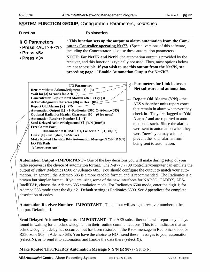
AES•IntelliNet Central Alarm Reporting System net7X / net77-b1.p65 Rev B.1 11/02/00
AES•IntelliNet Network Management Program Section 3 pg 3240-0551u
Automation Output - IMPORTANT - One of the key decisions you will make during setup of yourradio receiver is the choice of automation format. The Net77 / 7700 controller/computer can emulate theoutput of either Radionics 6500 or Ademco 685. You should configure the output to match your auto-mation. In general, the Ademco 685 is a more capable format, and is recommended. The Radionics is aproven but simpler format. If you are using some of the new interfaces for NAPCO, CADDX, AES-IntelliTAP, choose the Ademco 685 emulation mode. For Radionics 6500 mode, enter the digit 1; forAdemco 685 mode enter the digit 2. Default setting is Radionics 6500. See Appendices for completedescription of codes
Automation Receiver Number - IMPORTANT - The output will assign a receiver number to theoutput. Default is 1.
Send Delayed Acknowledgments - IMPORTANT - The AES subscriber units will report any delaysfound in waiting for an acknowledgment in their routine communications. This is an indicator that anacknowledgment delay has occurred, but has been restored in the R903 message in Radionics 6500, orR356 zone 903 in Ademco 685. You have the choice to NOT send these messages to your automation(select N), or to send it to automation and handle the data there (select Y).
Make Routed Thru/RcrRdy Automation Message N Y/N (R 907) - Set to N.
I/O ParametersRetries without Acknowledgment [3] (3)Wait for [3] Seconds for Ack (3)Concentrator Skips to Next Modem after 3 Try (3)Acknowledgment Character [06] in Hex (06)Report Old Alarms [Y] Y/NAutomation Output [1] (1=Radionics 6500, 2=Ademco 685)Optional Radionics Header Character [00] (0 for none)Automation Receiver Number [1] (1)Send Delayed Acknowledgments [Y] (Y/N (R903))Free Comm Port: Automation = 0, USDI = 1, LoJack = 2 [ 1] (0,1,2)Units: [0] (0=English, 1=Metric)Make Routed Thru/RcrRdy Automation Message N Y/N (R 907)I/O File Path [c:\aes\streets.gps]
Parameters for Link betweenNet software and automation.
Report Old Alarms (Y/N) - theAES subscriber units report zonesthat remain in alarm whenever theycheck in. They are flagged as "OldAlarms" and are reported to auto-mation as such. Since the alarmswere sent to automation when theywere "new", you may wish toprevent the "old" alarms frombeing sent to automation.
Function Explanation
• This function sets up the output to alarm automation from the Com-puter / Controller operating Net77. (Special versions of this software,including the Concentrator, also use these automation parameters.
NOTE: For Net7K and Net99, the automation output is provided by thereceiver, and this function is typically not used. Thus, most options beloware not accessible. If you wish to use this output from the Net7K, seepreceding page - "Enable Automation Output for Net7K".
I/O Parameters• Press <ALT> + <Y>• Press <5>• Press <3>
SYSTEM FUNCTION GROUP, Configuration Parameters, continued

AES•IntelliNet Central Alarm Reporting System net7X / net77-b1.p65 Rev B.1 11/02/00
AES•IntelliNet Network Management Program Section 3 pg 3340-0551u
6. RESTORE AUTOMATION• Press <F8>
Function Explanation
7. PRINT ERROR LOG•Hold <ALT>, press <Y>•Press <8>
8. FILTER CHKINS & ACKS• Press <F7>
• To filter out screen "clutter", this function prevents noncriticalcheck-in and acknowledgment messages from appearing on thescreen. This is "toggle" function: to turn on the filter, press F7; a"checkmark" figure will appear on the lower message bar of thescreen with the filter is on. To turn off the filter, press F7 again.
• This is a diagnostic function. A log of system status problems(such as disconnected cables, lost links to automation, etc.) isstored in a file. This function prints out that file. Have the printerready with plenty of paper - this file may print many pages. Press<ESC> during printing to abort.
• For Concentrators Only: If the link between this software andautomation has been taken off line for any reason, this reestab-lishes the link to automation.
Note: In Net77, "Restore" is automatic.
Note: This function does not apply to the link between an AES7000 or 7003 Series receiver and automation.
SYSTEM FUNCTION GROUP, continued
9. FORWARDING TOGGLE• Press <ALT>+<K>
• This one command allows you to globally enable or disable theforwarding function. It affects only those units that have beenprogrammed for forwarding. (For more information, see thesection on Database Group / Edit Radio Forward Table.) A pop upwindow shows you the current status global forwarding (On orOff). Enter Y/yes or N/no to change the status.

AES•IntelliNet Central Alarm Reporting System net7X / net77-b1.p65 Rev B.1 11/02/00
AES•IntelliNet Network Management Program Section 3 pg 3440-0551u
Interpreting Screen MessagesThe network communications which appear on the monitoring screen are unscrambled datapackets as sent and received by this receiver.
WHO, WHAT, WHEN, WHERE...
The following information can be extracted from the sample message above:• The message was sent on September 15th at 12:57:01.• The message originated at subscriber unit #9876, and is addressed to Unit #0000 (the central station).• This specific message is being sent by subscriber #1234 - a "repeater" in the message path• This specific message is being sent to Unit #0000 (the designation for the central station).• This is a Unit Check In / Automatic Test Timer Message. It says that all is well.• The type of routing used by the unit in its communication.
• (LNR): automatic routing was used.• (LNRT): automatic routing was used, but a trace was placed on the route (each ID that assisted
in forwarding the message is added to the packet).
• (EXR): an explicit route was specified by an operator or computer.
• "Data" refers to all the data attached or included with this communication. In this case, the data indi-cates that the unit is OK.
• The direction of data flow has also been established. The unit ID before the "-> is the originating unitand the one after the "->" is the destination unit.
continued ->
Sep 15 12:57:01 [#6B, 9876..0000 1234->0000 (LNRT) Unit Check In](Data 015: Unit 9876 is OK
Date
Time
Packet NumberInternal Tracking #
Original Sender
Type of Routing(Auto routing, withtrace)
Type of PacketUltimateDestination
Current Sender of this Packet "From"
Message, in this example, a Status message(Structure and content varies)
SAMPLE CHECK IN MESSAGE:
Current Destinationof thisPacket "To"

AES•IntelliNet Central Alarm Reporting System net7X / net77-b1.p65 Rev B.1 11/02/00
AES•IntelliNet Network Management Program Section 3 pg 3540-0551u
Interpreting Screen Messages, continued
Sep 15 13:19:01 [#7C, 5678..0000 1234->0000 (LNRT) Alarm](Data 007: (New) Type=Alarm ID=5678 Zone 001
Date
Time UltimateDestination
DesignatesOld or New Message
SAMPLE ALARM MESSAGE:
Original Sender
WHO, WHAT, WHEN, WHERE...The above example shows an alarm message being sent by a subscriber unit to the central station viaanother unit.• The message originated from the unit #5678 - this is where the alarm occurred.• The screen displays the message in red.• The message was relayed through subscriber unit #1234 using the automatic routing (LNRT). Sub-scriber unit #1234 is acting as a repeater, forwarding a message from unit 5678 to the central station.• The data in the packet is a New Alarm.• The data in the packet is an Alarm on Zone 001 of the subscriber unit. (IntelliTap or FDX data from analarm control panel may not be displayed here.)• Sometimes the data is shown in its raw hex format.
(Format of 2nd line varies)Message - Alarm, Zone 1,(Red Color Display)
Type of Packet
Type of Routing(Auto routing, withtrace - updates therouting table forthis unit)
Current Destinationof thisPacket"To"
Current Sender of this Packet "From"
Packet NumberInternal Tracking #

AES•IntelliNet Central Alarm Reporting System net7X / net77-b1.p65 Rev B.1 11/02/00
AES•IntelliNet Network Management Program Section 3 pg 3640-0551u
PRINTED WARNING MESSAGES:
Refers to printer connected to the AES 7100 or 7700 controller, output by "Net" program.
Structure: <Day/Date> <Time> <year>, <Event Type> <Description>
Error Messages:
ERROR -- Event not Reported to Automation -- nnnua nnnn A 000 This message appears if Net software is unable to send an alarm event to the automation software; digits at endof message is the data that could not be sent (applies only to Net77, or to Net7K/Net99 with automation outputactivated).
Radio Transceiver Fault Indicates a problem with the transceiver.
Radio Transceiver Tamper Fault Indicates a tamper problem with the transceiver or cables between receiver and transceiver.
Central Receiver in Standby Mode Indicates that Receiver has been set to Standby mode, is NOT Active and cannot respond to network traffic.
Multiple Central Stations Detected Indicates that more than one central station is operating on the same network (i.e. same frequency, same cipher /dealer code). This is SERIOUS fault - Be sure that ONLY ONE Receiver is ACTIVE.
ERROR - No Acknowledge from Automation Computer Indicates problem with automation software, or trouble with the link between the controller/computer and theautomation computer and software (applies only to Net77, or to Net7K/Net99 with automation output activated)
ON- SCREEN WARNING MESSAGESThe following are messages that may appear on the screen while Net77 is running. They are displayed at the baseof the screen and are typically highlighted in red.
A Warning Tone usually accompanies a Warning Message. To SILENCE WARNING TONE that accom-panies an error condition, PUSH F3 key. For Net77/UL, a "Chirp" tone will continue to sound approxi-mately every 30 seconds until condition clears.
Screen Message Description
Radio Transceiver Tamper Fault Cover of 7730 was removed, cable cut / tamper (Net77 only)Error No Target ID No ID was entered, cannot execute functionCentral Receiver in Standby Receiver connected to 7700 is in Standby / NOT Active (Net77)Radio Transceiver Fault 7730 radio transceiver problem (Net77 only)ERROR-Check Central Receiver ---
Comm Watchdog Timeout Central Receiver has a problem; may have already restoredTimed Out Writing to Port (DSR False) Central Receiver not responding, cable may be disconnectedTimed Out Reading Port (no Chars) Central Receiver not responding, cable may be disconnectedError-Check Central Receiver-Serial Cable Check Cable