a multi-stage linear approach to structure from motion · a multi-stage linear approach to...
TRANSCRIPT

A multi-stage linear approach to structure frommotion
Sudipta N. Sinha1, Drew Steedly2, and Richard Szeliski1
1 Microsoft Research, Redmond, USA2 Microsoft, Redmond, USA
{sudipsin,steedly,szeliskli}@microsoft.com
Abstract. We present a new structure from motion (Sfm) techniquebased on point and vanishing point (VP) matches in images. First, allglobal camera rotations are computed from VP matches as well as rel-ative rotation estimates obtained from pairwise image matches. A newmulti-staged linear technique is then used to estimate all camera trans-lations and 3D points simultaneously. The proposed method involvesfirst performing pairwise reconstructions, then robustly aligning thesein pairs, and finally aligning all of them globally by simultaneously es-timating their unknown relative scales and translations. In doing so,measurements inconsistent in three views are efficiently removed. Unlikesequential Sfm, the proposed method treats all images equally, is easy toparallelize and does not require intermediate bundle adjustments. Thereis also a reduction of drift and significant speedups up to two order ofmagnitude over sequential Sfm. We compare our method with a standardSfm pipeline [1] and demonstrate that our linear estimates are accurateon a variety of datasets, and can serve as good initializations for finalbundle adjustment. Because we exploit VPs when available, our approachis particularly well-suited to the reconstruction of man-made scenes.
1 Introduction
The problem of simultaneously estimating scene structure and camera motionfrom multiple images of a scene, referred to as structure from motion (Sfm),has received considerable attention in the computer vision community. Recentlyproposed Sfm systems [2–5] have enabled significant progress in image-basedmodeling [3] and rendering [4, 5]. Most Sfm systems [2–6] are either sequen-tial, starting with a small reconstruction and then incrementally adding in newcameras by pose estimation and 3D points by triangulation, or hierarchical [7,8] where smaller reconstructions are progressively merged. Both approaches re-quire intermediate bundle adjustment [9] and multiple rounds of outlier removalto minimize error propagation as the reconstruction grows. This can be compu-tationally expensive for large datasets.
This paper investigates ways to compute a direct initialization (estimates forall cameras and structure) in an efficient and robust manner, without any inter-mediate bundle adjustment. We propose a new multi-stage linear approach forthe structure and translation problem, a variant of Sfm where camera rotations

2 Sudipta N. Sinha et al.
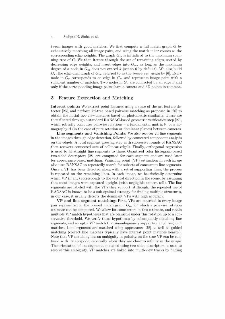
Vanishing Point (VP) Detection
2-view Matching
line segments
Line + VP Matching VP
tracks
F / H +
pointmatches
Feature Extraction
GlobalRotation
Estimation
Linear Reconstruction
2-view reconstruction
Robust Alignment
Global Scale + Translation Estimation
VPs
point tracks
interestpoints
Images
Fig. 1. Overview: First, all camera rotations are estimated. All structure and transla-tion parameters are then directly estimated using a new multi-stage linear approach.
are already known. A robust approach for first recovering all the global camerarotations based on vanishing points (VPs) and pairwise point matches is alsodescribed. Because we exploit VPs when available, our approach is particularlywell-suited for man-made scenes, a topic that has received a lot of recent atten-tion [5, 10–13]. When VPs are absent, the rotations can be computed from onlypairwise point matches using one of the methods described in [14–16].
Approaches for such direct initialization of cameras and structure have beenexplored in the past. Factorization based approaches, such as [17], usually requireall points to be visible in all views, or do not scale to large scenes with largeamounts of missing data [18]. Linear reference-plane based techniques [11], canhandle missing data, but minimize an algebraic error. This can cause pointsclose to infinity to bias the reconstruction, unless the measurements are correctlyweighted, which in turn requires a good initialization.
Direct linear methods [11, 19] also cannot cope with outliers, which are morecommon when matching features in unordered image datasets, as compared totracking features in video. Outliers are also common in architectural scenes dueto frequently repeating structures. Such outliers are caused by mismatches thatsurvive pairwise epipolar geometry estimation and get merged with good matchesin other views to form long, erroneous tracks.
Recently, the L∞ framework for solving multi-view geometry problems, wherethe maximum reprojection error of the measurements is minimized rather thanthe sum of squared errors, was shown to be applicable to the problem of structureand translation estimation, where camera rotations are known apriori [16, 20–22]. Although a global minimum can be computed using convex optimizationtechniques, L∞ problems become computationally expensive for a large numberof variables [21], and are also not robust to outliers. The known outlier removalstrategies for L∞ norm, such as [20], do not scale to large problems [16, 21].
Instead of directly solving a linear system as in [11, 19], we first performpairwise reconstructions, and then robustly align pairs of such reconstructions,thereby detecting matches consistent over three views. In a subsequent linearstep, these reconstructions are jointly aligned by estimating their unknown rel-ative scales and translations. Once approximate depths are available, a direct,linear method can be used to jointly re-estimate the camera and point locations.A final bundle adjustment step refines all camera parameters (including rota-tions) and structure parameters. Our proposed approach is fast, treats all imagesequally, and is easy to parallelize. Our technique could also be extended to in-corporate linear constraints for 3D lines with known directions, and coplanarityconstraints on 3D points and lines, as described in [11, 23].

A multi-stage linear approach to structure from motion 3
facade1 facade2 statue(75 cams, 93K pts) (38 cams, 59K pts) (111 cams, 34K pts)
Fig. 2. The proposed method generates accurate reconstructions and is significantlyfaster than a standard sequential Sfm pipeline [1] (see Table 2).
For estimating rotations, we show the benefit of exploiting parallel scene lines,which are assumed to be either vertical, or orthogonal to the vertical direction.This is more general than Manhattan-world assumptions and is common in a va-riety of man-made scenes [13]. Currently, we assume known focal lengths (usingvalues present in exif tags) but these could also be estimated from orthogonalVPs [24]. Our method builds upon known techniques for estimating global rota-tions from VP matches [10, 15, 24], and pairwise relative rotation estimates [14–16]. However, unlike [10, 15] where omni-directional images with small baselineswere used, we perform VP matching on unordered regular images, which is amore difficult case. We show that when VPs can be accurately detected andmatched in images, the global rotation estimates can be very accurate. Figure 2shows some accurate reconstructions obtained using our proposed method.
2 Proposed Approach
Figure 1 provides an overview of the three stages of our Sfm pipeline. First,points, line segments, and vanishing points are extracted and matched in allimages. Next, camera rotations are estimated using vanishing points wheneverpossible, but also using relative rotation estimates obtained from pairwise pointmatches. Finally, all cameras and 3D points are directly estimated using a linearmethod, followed by a final bundle adjustment.
Notation and Preliminaries: In our Sfm formulation, a set of 3D pointsXj are observed by a set of cameras with projection matrices Pi. The i-th camerahas focal length fi and has a center of projection Ci. We assume camera intrinsicsof the form Ki = diag(fi, fi, 1), and denote camera pose (rotation, translation)by (Ri,ti) respectively, with Pi = Ki[Ri ti], and ti = −RiCi. The j-th point isobserved in the i-th camera at the point xij . A point at infinity in the directiondm, is observed at a VP vim in the i-th camera.
Match and Image-pair Graphs: From pairwise point matches, we forma pruned match graph Gm, consisting of nodes for each image and edges be-
4 Sudipta N. Sinha et al.
tween images with good matches. We first compute a full match graph G byexhaustively matching all image pairs, and using the match inlier counts as thecorresponding edge weights. The graph Gm is initialized to the maximum span-ning tree of G. We then iterate through the set of remaining edges, sorted bydecreasing edge weights, and insert edges into Gm, as long as the maximumdegree of a node in Gm does not exceed k (set to 6 by default). We also buildGr, the edge dual graph of Gm, referred to as the image-pair graph by [6]. Everynode in Gr corresponds to an edge in Gm and represents image pairs with asufficient number of matches. Two nodes in Gr are connected by an edge if andonly if the corresponding image pairs share a camera and 3D points in common.
3 Feature Extraction and Matching
Interest points: We extract point features using a state of the art feature de-tector [25], and perform kd-tree based pairwise matching as proposed in [26] toobtain the initial two-view matches based on photometric similarity. These arethen filtered through a standard RANSAC-based geometric verification step [27],which robustly computes pairwise relations – a fundamental matrix F, or a ho-mography H (in the case of pure rotation or dominant planes) between cameras.
Line segments and Vanishing Points: We also recover 2d line segmentsin the images through edge detection, followed by connected component analysison the edgels. A local segment growing step with successive rounds of RANSACthen recovers connected sets of collinear edgels. Finally, orthogonal regressionis used to fit straight line segments to these. Quantized color histogram-basedtwo-sided descriptors [28] are computed for each segment and are used laterfor appearance-based matching. Vanishing point (VP) estimation in each imagealso uses RANSAC to repeatedly search for subsets of concurrent line segments.Once a VP has been detected along with a set of supporting lines, the processis repeated on the remaining lines. In each image, we heuristically determinewhich VP (if any) corresponds to the vertical direction in the scene, by assumingthat most images were captured upright (with negligible camera roll). The linesegments are labeled with the VPs they support. Although, the repeated use ofRANSAC is known to be a sub-optimal strategy for finding multiple structures,in our case, it usually detects the dominant VPs with high accuracy.
VP and line segment matching: First, VPs are matched in every imagepair represented in the pruned match graph Gm for which a pairwise rotationestimate can be computed. We allow for some errors in this estimate, and retainmultiple VP match hypotheses that are plausible under this rotation up to a con-servative threshold. We verify these hypotheses by subsequently matching linesegments, and accept a VP match that unambiguously supports enough segmentmatches. Line segments are matched using appearance [28] as well as guidedmatching (correct line matches typically have interest point matches nearby).Note that VP matching has an ambiguity in polarity, as the true VP can be con-fused with its antipode, especially when they are close to infinity in the image.The orientation of line segments, matched using two-sided descriptors, is used toresolve this ambiguity. VP matches are linked into multi-view tracks by finding
A multi-stage linear approach to structure from motion 5
connected components, in the same way as is done for point matches, while alsoensuring that the polarity of the VP observations are in agreement. Note thatVP tracks are often disconnected, but different tracks that correspond to thesame 3D direction may subsequently get merged, as described next.
4 Computing Rotations
Given three orthogonal scene directions, d1 = [1, 0, 0]T, d2 = [0, 1, 0]T and d3
= [0, 0, 1]T, the global camera rotation in a coordinate system aligned with thedi’s, can be computed from the VPs corresponding to these directions.
vim = diag(fi, fi, 1)Ridm (1)
For each m, the mth column of Ri can be computed. In fact, two VPs are suffi-cient, since the third column can be computed from the other two.
4.1 Rotations from VP Matches
The rotation estimation method just described assumes that the directions {dm},are known. Our goal however, is to recover all camera rotations given M VPtracks, each of which corresponds to an unknown 3D direction. As some of theVPs were labeled as vertical in the images, we know which tracks to associatewith the unique up direction in the scene. Now, pairwise angles between all Mdirections are computed. Every image where at least two VPs were detectedcontributes a measurement. We rank the M directions with decreasing weights,where each weight is computed by counting the number of supporting line seg-ments over all images where a corresponding VP was detected. Next, we findthe most salient orthogonal triplet of directions such that at least one trackcorresponding to the vertical direction is included.
For all images where at least two of these directions are observed, camerarotations can now be computed using (1). If some of the remaining (M -3) direc-tions were observed in any one of these cameras, those can now be computed aswell. This step is repeated until no more cameras or directions can be added. Thisproduces the first camera set—a subset of cameras with known rotations, consis-tent with a set of 3D directions. We repeat the process and obtain a partition ofthe cameras into mutually exclusive camera sets, some of which may potentiallyshare a common direction (typically this is the up direction). A camera that seesfewer than two matched VPs generates a set with a single element.
4.2 Global Rotations
If a single camera set is found, we are done. Otherwise, the K camera sets mustbe rotationally aligned to obtain the global camera rotations. A unique solutioncan be found by fixing the rotation of one of the camera sets to identity. Note thatwe have an estimate of the relative rotation between camera pairs in the matchgraph. Let us denote this rotation involving the i-th and j-th cameras, chosen

6 Sudipta N. Sinha et al.
from camera sets a and b respectively, by the quaternion qij . Each estimate ofqij provides a non-linear constraint relating the unknown rotations of the twocamera sets denoted by qa and qb respectively.
qa = (qai · qij · (qb
j)−1)qb (2)
where qai and qb
i denotes the known rotations of the i-th and j-th camera in theirown camera sets. As proposed by [16], by ignoring the orthonormality constraintson the quaternions, we linearly estimate the set {qk}. When the vertical VPs aredetected in a rotation set, the corresponding quaternion represents an unknown1-dof rotation in the horizontal plane, as the vertical direction is assumed to beunique. We solve the full 4-dof system (2), and snap the near vertical rotations(within 5o degrees of each other) to be vertical. The scene directions within 5o
of each other are also snapped together, and all the rotations are re-estimatedunder these additional constraints. This is useful in scenarios such as identifyingparallel lines on opposite sides of a building, which are never seen together.
In the absence of VPs, rotations can be recovered via the essential matricesobtained from pairwise point matches for image pairs with an adequate numberof matches. In [15], relative rotations were chained over a sequence followed bya non-linear optimization of the global rotations. We perform the chaining on amaximum spanning tree of the match graph Gm and then use its nontree edges inthe non-linear optimization step. The rotations could also have been initializedusing linear least squares (by ignoring the orthonormality constraint of rotationmatrices) [16], or by averaging on the Lie group of 3D rotations [14].
5 Linear Reconstruction
When the intrinsics Ki and rotations Ri are known, every 2D image point xij
can be normalized into a unit vector, xij = (KiRi)−1xij , which is related to the
j-th 3D point Xj (in non-homogenous coordinates) as,
xij = d−1ij (Xj −Ci), (3)
where dij is the distance from Xj to the camera center Ci. Note that (3) iswritten with dij on the right side to ensure that measurements are weighted byinverse depth. Hereafter, xij is simply denoted as xij . By substituting approxi-mate values of dij , if known, (3) can be treated as a linear equation in Xj andCi. All measurements together form a sparse, non-homogeneous, linear system,which can be solved to estimate the cameras and points all at once. These canbe further refined by iteratively updating dij and solving (3). Notice that if wemultiply the above equation by the rotation and calibration matrices and divideby zij , where zij is the distance between Xj and Ci projected along the cameraaxis (the last row of Ri), we get the usual pixel matching error. Therefore, ifthe focal lengths for all the cameras are similar, minimizing (3) is similar to theusual bundle adjustment equations (when the depths are approximately known,and ignoring any robust cost function).
A multi-stage linear approach to structure from motion 7
An alternative approach [11] is to eliminate dij from (3), since dijxij× (Xj−Ci) = 0. All cameras and points can be directly computed by solving a sparse,homogeneous system, using SVD (or a sparse eigensolver), and fixing one ofthe cameras at the origin to remove the translational ambiguity. The points atinfinity must be detected and removed before this method can be used. Sincethis method minimizes a purely algebraic cost function, if the linear equationsare not weighted correctly, points farther away from the camera may bias thelinear system, resulting in large reconstruction errors. Neither of these methodscan handle outliers in the 2D observations, which are inevitable in many cases.
In this paper, instead of directly solving (3) for all cameras and points at once,we propose to independently compute two-view reconstructions for camera pairsthat share points in common. Various approaches for computing two-view re-constructions are known and the situation is even simpler for a pair of camerasdiffering by a pure translation. Next, pairs of such reconstructions, sharing acamera and 3D points in common, are robustly aligned by estimating their rel-ative scales and translations. This key step allows us to retain matches found tobe consistent in the three views. Finally, once a sufficient number of two-view re-constructions have been pairwise aligned, we can linearly estimate the unknownscale and translation of each individual reconstruction, which roughly brings allof them into global alignment. An approximate estimate of depth dij can nowbe computed and substituted into (3), and the linear system can be solved withthe outlier-free tracks obtained by merging three-view consistent observations.We now describe these steps in more detail.
5.1 Two-view reconstruction
A pairwise reconstruction for cameras (a,b), treated as a translating pair, isdenoted as Rab = {Cab
a ,Cabb , {Xab
j }} where the superscript denotes a local co-ordinate system. Under pure translation, it is known that the epipoles in thetwo images coincide, and all points in the two views xaj and xbj are collinearwith the common epipole e, also known as the focus of expansion (FOE), i.e.xTaj [e]×xbj = 0. The epipole e is a vector that points along the baseline for the
translating camera pair. We compute e by finding the smallest eigenvector of a3×3 matrix produced by summing the outer product of all 2D lines l = xaj×xbj ,and then choose Cab
a = 0 and Cabb = e, corresponding to a unit baseline. Each
point Xabj is then triangulated using the linear method.
xkj × (Xabj −Cab
k ) = 0, for k ∈ {a, b}. (4)
Finally, we remove all points reconstructed behind both cameras and the oneswith small triangulation angles (< 1◦).
5.2 Robust alignment
Each pairwise reconstruction Rab involving cameras (a,b) differs from a globalreconstruction by 4-dofs, i.e. an unknown scale sab and translation tab, unique up

8 Sudipta N. Sinha et al.
SS-1Xj
ab
a b
R
ab
xaj xbj
RbcXj
bc
b c
xbj xcj
Fig. 3. The symmetric transfer error of the 3D similarity (scale and translation) trans-formation S from Rab to Rbc is the sum of distances between the observed points xaj ,xbj , xcj and the projected points shown in grey.
to an arbitrary global scale and translation. Suppose, Rbc and Rab share camerab and some common 3D points. Using MLESAC [29], we robustly align Rab toRbc by computing a 4-dof 3D similarity Sabbc (parameterized by relative scale sabbcand translation tabbc ). A hypothesis is generated from two 3D points common toboth reconstructions. These are chosen by randomly sampling two common 3Dpoints, or only one common point when the camera center of b is chosen as thesecond point. Assuming exact correspondence for one of the two points in Rbc
and Rab gives a translation hypothesis t. A scale hypothesis s is computed byminimizing the image distance between the observed and reprojected points forthe second 3D point. This can be computed in closed form as the reprojectedpoint traces out a 2D line in the image as the scale varies. The hypothesis (s,t)is then scored using the total symmetric transfer error for all common 3D pointsin all three images. As illustrated in Figure 3, this error for each Xj is equal to∑
k
d(xkj , f
abk (S−1Xbc
j ))
+∑k
d(xkj , f
bck (SXab
j ))
(5)
Here, function fabk projects a 3D point into each of the two cameras of Rab wherek ∈ {a, b}, f bck is defined similarly for Rbc, and d robustly measures the distanceof the projected points from the original 2D observations xkj , where k ∈ {a, b, c}.
5.3 Global scale and translation estimation
Once a sufficient number of transformations (sabbc , tabbc ) between reconstructionsRab andRbc are known, their absolute scale and translations, denoted by (sab,tab)and (sbc,tbc), can be estimated using the relation,
sbcX + tbc = sbcab(sabX + tab) + tbcab, (6)
where X is an arbitrary 3D point in global coordinates. Eliminating X, gives usfour equations in eight unknowns:
wbcab(s
bc − sbcabsab) = 0,
wbcab(s
bctbc) = wbcab(s
bcabt
ab + tbcab). (7)
Here, the weight wbcab is set to the number of three-view consistent points found
common to Rab and Rbc. The scale of any one reconstruction is set to unity andits translation set to zero to remove the global scale and translational ambiguity.

A multi-stage linear approach to structure from motion 9
The size of the linear system (7), depends on the number of edges in theimage-pair graph Gr, (defined in Section 2), whose construction is describedbelow. Any spanning tree of Gr will result in a linear system with an exactsolution, but a better strategy is to use the maximum spanning tree, computedusing wbc
ab as the edge weight between nodes corresponding to Rab and Rbc.Solving an over-determined linear system using additional edges of Gr is usuallyeven more reliable. Note that even when the match graph Gm is fully connected,Gr may be disconnected. This can happen if a particular pairwise reconstructiondid not share any 3D points in common with any other pair. However, to obtaina reconstruction of all the cameras in a common coordinate system, all we needis a connected sub-graph of Gr, which covers all the cameras. We denote thisconnected subgraph by G′ and compute it as follows.
To construct Gr, for each camera we first form a list of pairwise reconstruc-tions the camera belongs to. We sort these reconstructions in increasing order ofsome accuracy measure (we use the number of reconstructed points with less than0.6 pixel residual error). We iterate through the sorted list of reconstructions,labeling the ones that contain fewer than τ accurately reconstructed points (τ =20 by default), provided it is not the only reconstruction a particular camera ispart of. Next, we remove all the nodes corresponding to labeled reconstructionsfrom Gr, along with the edges incident on these nodes. The maximum spanningtree of the largest connected component of Gr, denoted by G′, is then computed.Finally, we sort the remaining edges in Gr in decreasing order of weights, and it-erate through them, adding an edge to G′, as long as the maximum vertex degreein G′ does not exceed k′ (k′ = 10 by default). With n cameras, our pruned matchgraph Gm with maximum vertex degree k has at most O(kn) edges. Hence, Gr
has O(kn) nodes as well. Every node in Gm with degree d, gives rise to(d2
)edges
in Gr. Therefore, Gr has O(nk2) edges. Thus, both the number of pairwise re-constructions as well as the number of pairwise alignment problems are linearin the number of cameras. Moreover, each of the pairwise reconstructions andsubsequent alignment problems can be easily solved in parallel.
6 Results
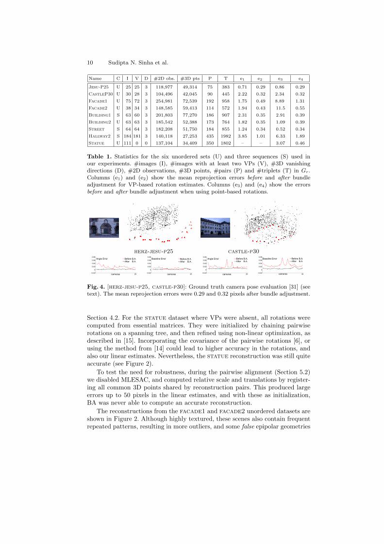
We have tested our approach on nine datasets (three sequences and six unorderedsets), many of which are representative of common man-made scenes. Radialdistortion was removed in advance using ptlens [30]. Our linear estimates hadlow mean reprojection error in the range of 0.7–3.8 pixels, as shown in Columne1 in Table 1, prior to bundle adjustment (BA) and without further optimizationof the rotations or intrinsics. A subsequent full BA on all cameras and points,initialized with these estimates, converged in only 4–10 iterations, with meanreprojection errors of 0.3–0.5 pixels for most of the datasets (Column e2).
The linear estimates were more accurate when VPs were used for recoveringrotations (column e1 v.s. e3 in Table 1). In some of our datasets, multiple groupsof parallel lines were present and reliable VPs could be matched in most images(see columns v–d in Table 1). In some of these cases, up to five rotation setshad to be aligned based on point matches, using the approach described in
10 Sudipta N. Sinha et al.
Name C I V D #2D obs. #3D pts P T e1 e2 e3 e4
Jesu-P25 U 25 25 3 118,977 49,314 75 383 0.71 0.29 0.86 0.29
CastleP30 U 30 28 3 104,496 42,045 90 445 2.22 0.32 2.34 0.32
Facade1 U 75 72 3 254,981 72,539 192 958 1.75 0.49 8.89 1.31
Facade2 U 38 34 3 148,585 59,413 114 572 1.94 0.43 11.5 0.55
Building1 S 63 60 3 201,803 77,270 186 907 2.31 0.35 2.91 0.39
Building2 U 63 63 3 185,542 52,388 173 764 1.82 0.35 1.09 0.39
Street S 64 64 3 182,208 51,750 184 855 1.24 0.34 0.52 0.34
Hallway2 S 184 181 3 140,118 27,253 435 1982 3.85 1.01 6.33 1.89
Statue U 111 0 0 137,104 34,409 350 1802 – – 3.07 0.46
Table 1. Statistics for the six unordered sets (U) and three sequences (S) used inour experiments. #images (I), #images with at least two VPs (V), #3D vanishingdirections (D), #2D observations, #3D points, #pairs (P) and #triplets (T) in Gr.Columns (e1) and (e2) show the mean reprojection errors before and after bundleadjustment for VP-based rotation estimates. Columns (e3) and (e4) show the errorsbefore and after bundle adjustment when using point-based rotations.
herz-jesu-p25 castle-p30
25−0.02
0
0.02
0.04
0.06
0.08Angle Error
cameras
Before B.A.After B.A.
25−0.02
0
0.02
0.04
0.06
0.08Baseline Error
cameras
Before B.A.After B.A.
30−0.02
0
0.02
0.04
0.06
0.08Angle Error
cameras
Before B.A.After B.A.
30−0.02
0
0.02
0.04
0.06
0.08Baseline Error
cameras
Before B.A.After B.A.
Fig. 4. [herz-jesu-p25, castle-p30]: Ground truth camera pose evaluation [31] (seetext). The mean reprojection errors were 0.29 and 0.32 pixels after bundle adjustment.
Section 4.2. For the statue dataset where VPs were absent, all rotations werecomputed from essential matrices. They were initialized by chaining pairwiserotations on a spanning tree, and then refined using non-linear optimization, asdescribed in [15]. Incorporating the covariance of the pairwise rotations [6], orusing the method from [14] could lead to higher accuracy in the rotations, andalso our linear estimates. Nevertheless, the statue reconstruction was still quiteaccurate (see Figure 2).
To test the need for robustness, during the pairwise alignment (Section 5.2)we disabled MLESAC, and computed relative scale and translations by register-ing all common 3D points shared by reconstruction pairs. This produced largeerrors up to 50 pixels in the linear estimates, and with these as initialization,BA was never able to compute an accurate reconstruction.
The reconstructions from the facade1 and facade2 unordered datasets areshown in Figure 2. Although highly textured, these scenes also contain frequentrepeated patterns, resulting in more outliers, and some false epipolar geometries

A multi-stage linear approach to structure from motion 11
building1 Bundler (61 cams, 74K pts) Ours (61 cams, 77K pts)
building2 Bundler (63 cams, 50K pts) Ours (63 cams, 52K pts)
Fig. 5. [building1,building2]: Our method is comparable to Bundler in terms ofaccuracy, but is two orders of magnitude faster (see Table 2 for details).
630
5
10
15
cameras
deg
ree
s)
FACADE 1
380
1
2
3
4
cameras
deg
ree
s)
FACADE 2
610
2
4
6
cameras
deg
ree
s)
BUILDING 1
630
2
4
cameras
deg
ree
s)
BUILDING 2
Rot-VP
Rot-pts
Fig. 6. Accuracy test of global rotations estimates (VP-based v.s. pure point-based)compared to the final rotations after bundle adjustment (better seen in color).
(this is also noted by [16]). The reconstructions from our linear method showedno drift, and were visually accurate even without BA. In comparison, the refer-ence plane based linear method [11] only worked on small selected subsets of theinput, and failed on most of the other datasets too, mainly due to its inabilityto handle points at infinity and its lack of robustness.
We evaluated our method on two ground truth datasets from Strecha et.al. [31] – HerzJesu-P25 and Castle-P30. Our reconstructions, shown in Fig-ure 4, are quite accurate. We compared our camera pose estimates (before andafter BA) with ground truth, using camera centers for registration and thencomparing errors in baseline lengths and angles between camera optical axes.Figure 4 shows the average error for each camera over all possible baselines. ForHerzJesu-P25, most cameras had less than 2% errors (baseline as well as an-gle) while the worst had 4% angle and 2% baseline error. These reduced to lessthan 1% after BA. The worst two out of 30 cameras in Castle-P30 initiallyhad 7% error (due to small inaccuracies in rotation estimates), but the angleand baseline error in all cameras went below 1% and 2% respectively, after BA.
12 Sudipta N. Sinha et al.
street Bundler (65 cams, 21K pts) Ours (65 cams, 61K pts)
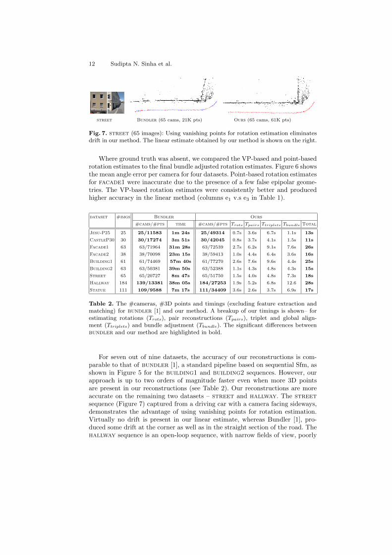
Fig. 7. street (65 images): Using vanishing points for rotation estimation eliminatesdrift in our method. The linear estimate obtained by our method is shown on the right.
Where ground truth was absent, we compared the VP-based and point-basedrotation estimates to the final bundle adjusted rotation estimates. Figure 6 showsthe mean angle error per camera for four datasets. Point-based rotation estimatesfor facade1 were inaccurate due to the presence of a few false epipolar geome-tries. The VP-based rotation estimates were consistently better and producedhigher accuracy in the linear method (columns e1 v.s e3 in Table 1).
dataset #imgs Bundler Ours
#cams/#pts time #cams/#pts Trots Tpairs Ttriplets Tbundle Total
Jesu-P25 25 25/11583 1m 24s 25/49314 0.7s 3.6s 6.7s 1.1s 13s
CastleP30 30 30/17274 3m 51s 30/42045 0.8s 3.7s 4.1s 1.5s 11s
Facade1 63 63/71964 31m 28s 63/72539 2.7s 6.2s 9.1s 7.6s 26s
Facade2 38 38/70098 23m 15s 38/59413 1.0s 4.4s 6.4s 3.6s 16s
Building1 61 61/74469 57m 40s 61/77270 2.6s 7.6s 9.6s 4.4s 25s
Building2 63 63/50381 39m 50s 63/52388 1.1s 4.3s 4.8s 4.3s 15s
Street 65 65/20727 8m 47s 65/51750 1.5s 4.0s 4.8s 7.3s 18s
Hallway 184 139/13381 38m 05s 184/27253 1.9s 5.2s 6.8s 12.6 28s
Statue 111 109/9588 7m 17s 111/34409 3.6s 2.6s 3.7s 6.9s 17s
Table 2. The #cameras, #3D points and timings (excluding feature extraction andmatching) for bundler [1] and our method. A breakup of our timings is shown– forestimating rotations (Trots), pair reconstructions (Tpairs), triplet and global align-ment (Ttriplets) and bundle adjustment (Tbundle). The significant differences betweenbundler and our method are highlighted in bold.
For seven out of nine datasets, the accuracy of our reconstructions is com-parable to that of bundler [1], a standard pipeline based on sequential Sfm, asshown in Figure 5 for the building1 and building2 sequences. However, ourapproach is up to two orders of magnitude faster even when more 3D pointsare present in our reconstructions (see Table 2). Our reconstructions are moreaccurate on the remaining two datasets – street and hallway. The streetsequence (Figure 7) captured from a driving car with a camera facing sideways,demonstrates the advantage of using vanishing points for rotation estimation.Virtually no drift is present in our linear estimate, whereas Bundler [1], pro-duced some drift at the corner as well as in the straight section of the road. Thehallway sequence is an open-loop sequence, with narrow fields of view, poorly

A multi-stage linear approach to structure from motion 13
textured surfaces, and predominantly forward motion. Our reconstruction shownin Figure 8, is qualitatively accurate with no rotational drift, although some driftin scale can be noticed with the camera path overlaid on the floor plan. In com-parison, bundler produced an incomplete reconstruction of the hallway whereonly 139 out of the 184 cameras were reconstructed.
Bundler (139 cams, 13K pts) Ours (184 cams, 27K pts)
Fig. 8. hallway (184 images): Unlike bundler, our method reconstructs the full hall-way. (c) The camera path from our reconstruction overlaid on the floor plan.
7 Conclusions
We have developed a complete Sfm approach, which uses vanishing points whenpossible, and point matches to first recover all camera rotations, and then simul-taneously estimates all cameras positions and points using a multi-stage linearapproach. Our method is fast, easy to parallelize, treats all images equally, effi-ciently copes with substantial outliers, and removes the need for frequent bundleadjustments on sub-problems. Its accuracy and efficiency is demonstrated on avariety of datasets. In the future, we plan to extend bundle adjustment to incor-porate constraints on camera rotations based on vanishing points and 2D linecorrespondences. We also plan to make our approach robust to the presence offalse epipolar geometries [16] and test it on large Internet photo collections [6].
References
1. Snavely, N.: Bundler (2007) http://phototour.cs.washington.edu/bundler/.2. Schaffalitzky, F., Zisserman, A.: Multi-view matching for unordered image sets, or
“How do i organize my holiday snaps?”. In: ECCV. (2002) 414–4313. Pollefeys, M., Gool, L.J.V., Vergauwen, M., Verbiest, F., Cornelis, K., Tops, J.,
Koch, R.: Visual modeling with a hand-held camera. IJCV 59 (2004) 207–2324. Snavely, N., Seitz, S.M., Szeliski, R.: Photo Tourism: exploring photo collections
in 3d. ACM Trans. Graph. 25 (2006) 835–8465. Agarwal, S., Snavely, N., Simon, I., Seitz, S.M., Szeliski, R.: Building Rome in a
Day. In: ICCV. (2009)6. Snavely, N., Seitz, S.M., Szeliski, R.: Skeletal graphs for efficient structure from
motion. In: CVPR. (2008) 1–8
14 Sudipta N. Sinha et al.
7. Fitzgibbon, A.W., Zisserman, A.: Automatic camera recovery for closed or openimage sequences. In: ECCV (1). (1998) 311–326
8. Gherardi, R., Farenzena, M., Fusiello, A.: Improving the efficiency of hierarchicalstructure-and-motion. In: CVPR. (2010)
9. Triggs, B., Mclauchlan, P.F., Hartley, R.I., Fitzgibbon, A.W.: Bundle adjustment- a modern synthesis. Lecture Notes in Computer Science 1883 (2000) 298–372
10. Antone, M., Teller, S.: Scalable extrinsic calibration of omnidirectional imagenetworks. IJCV 49 (2002) 143–174
11. Rother, C.: Linear multi-view reconstruction of points, lines, planes and camerasusing a reference plane. In: ICCV. (2003) 1210–1217
12. Brand, M., Antone, M.E., Teller, S.J.: Spectral solution of large-scale extrinsiccamera calibration as a graph embedding problem. In: ECCV (2). (2004) 262–273
13. Schindler, G., Krishnamurthy, P., Dellaert, F.: Line-based structure from motionfor urban environments. In: 3DPVT. (2006) 846–853
14. Govindu, V.M.: Lie-algebraic averaging for globally consistent motion estimation.CVPR 1 (2004) 684–691
15. Uyttendaele, M., Criminisi, A., Kang, S.B., Winder, S.A.J., Szeliski, R., Hartley,R.I.: Image-based interactive exploration of real-world environments. IEEE Com-puter Graphics and Applications 24 (2004) 52–63
16. Martinec, D., Padjla, T.: Robust rotation and translation estimation in multiviewreconstruction. In: CVPR. (2007)
17. Sturm, P.F., Triggs, B.: A factorization based algorithm for multi-image projectivestructure and motion. In: ECCV, Springer-Verlag (1996) 709–720
18. Tardif, J.P., Bartoli, A., Trudeau, M., Guilbert, N., Roy, S.: Algorithms for batchmatrix factorization with application to structure-from-motion. In: CVPR. (2007)
19. Hartley, R.I., Kaucic, R., Dano, N.Y.: Plane-based projective reconstruction. In:ICCV. (2001)
20. Sim, K., Hartley, R.: Removing outliers using the linf norm. In: CVPR. (2006)21. Agarwal, S., Snavely, N., Seitz, S.M.: Fast algorithms for L∞ problems in multiview
geometry. In: CVPR. (2008)22. Kahl, F., Hartley, R.I.: Multiple-view geometry under the L∞-Norm. PAMI 30
(2008) 1603–161723. Bartoli, A., Sturm, P.F.: Constrained structure and motion from multiple uncali-
brated views of a piecewise planar scene. IJCV 52 (2003) 45–6424. Caprile, B., Torre, V.: Using vanishing points for camera calibration. IJCV 4
(1990) 127–14025. Winder, S., Hua, G., Brown, M.: Picking the best DAISY. In: CVPR. (2009)26. Lowe, D.G.: Distinctive image features from scale-invariant keypoints. IJCV 60
(2004) 91–11027. Fischler, M.A., Bolles, R.C.: Random sample consensus: A paradigm for model
fitting with applications to image analysis and automated cartography. Commu-nications of the ACM 24 (1981) 381–395
28. Bay, H., Ferrari, V., Gool, L.V.: Wide-baseline stereo matching with line segments.In: CVPR. Volume 1. (2005) 329–336
29. Torr, P.H.S., Zisserman, A.: MLESAC: a new robust estimator with applicationto estimating image geometry. CVIU 78 (2000) 138–156
30. Niemann, T.: PTLens (2009) http://epaperpress.com/ptlens.31. Strecha, C., von Hansen, W., Gool, L.V., Fua, P., Thoennessen, U.: On bench-
marking camera calibration and multi-view stereo. In: CVPR. (2008)32. Havlena, M., Torii, A., Knopp, J., Pajdla, T.: Randomized structure from motion
based on atomic 3d models from camera triplets. CVPR 0 (2009) 2874–2881