6222 two door module - entry-master systems · 6222 technical operations manual overview the masi...
TRANSCRIPT

6222 Two Door Module
Technical Operations Manual
6222 Technical Operations Manual
TABLE OF CONTENTS
Specifications.......................................................................................................................................3 Overview..............................................................................................................................................4 Operations ...........................................................................................................................................5
Custom Access Mode .....................................................................................................................5 Standard Access Mode ...................................................................................................................5 Offline Access Mode .......................................................................................................................5 Offline – Memory .............................................................................................................................5 Putting Cards in Memory.................................................................................................................5 Clearing Memory .............................................................................................................................5 Stand-alone Set-up and Usage.......................................................................................................6
Wiring Inputs & Outputs.......................................................................................................................6 Relays .............................................................................................................................................6 Relay - Fail Safe – Fail Secure ......................................................................................................6 Relay - Standard Access Default Time ...........................................................................................6 LED Output......................................................................................................................................7 Sensor Inputs ..................................................................................................................................7 Request To Exit Sensor Input .........................................................................................................7 IN1 & IN2 Sensor Inputs .................................................................................................................7 Wiegand Reader/Keypad Inputs .....................................................................................................7 Mounting The 6222 Housing ...........................................................................................................8
Connections.........................................................................................................................................8 Power Connections .........................................................................................................................8 RS-485 Data Bus Connections .......................................................................................................8 Card Reader Connections...............................................................................................................9 Door Connections..........................................................................................................................10 RS-485 Data Bus Conventions and Explanations ........................................................................10 RS-485 Wiring ...............................................................................................................................10
Wiring Diagrams ................................................................................................................................11 Revision History ISSUE NUMBER ISSUE DATE DETAILS Written By Checked By Approved
By 1.1 12.17.03 Updated Format A. Baris C. Hospes D. Scott
The Part Number for this manual is 6222M. When ordering, please quote this number.
1

6222 Technical Operations Manual
Preface
This manual is provided as part of MASI’s ongoing commitment to our clients. It will help you maintain your new 6222 Two Door Module.
Copyright 2003 Modern Access Systems Inc. All rights reserved. Published in Canada. The information in this document is subject to change without notice and does not represent a commitment on the part of Modern Access Systems Inc. No part of this document may be reproduced or transmitted in any form or by any means, electronic or mechanical, including photocopying, recording, or information recording and retrieval systems, for any purpose other than the purchaser's personal use, without the express written permission of Modern Access Systems Inc. The information in this manual may contain technical inaccuracies or typographic errors, and may be changed, modified and/or incorporated into new revisions. Modern Access Systems Inc. #1 – 558 Massey Rd. Guelph, Ontario Canada N1K 1B4 TEL (519)766-4024 FAX (519)766-4025 Toll Free CAN (866)512-8374 USA (800)663-5715 [email protected] www.modernaccesssystems.com
2

6222 Technical Operations Manual
Specifications
SUPPLY VOLTAGE and Current: +16VAC 30VA Transformer AUXILIARY POWER OUTPUT: +12 VDC (+/-0.5), 2.0A Peak 1.5A continuous maximum AUXILIARY POWER FUSE: Internally fused, auto-reset OPERATING TEMPERATURE: 0°C to +50°C (32°F to 122°F) OPERATING HUMIDITY: 0% to 95% (no condensing) ENVIRONMENTAL: Non-weatherized - shield from elements WIEGAND DATA INPUTS: Standard 5-volt Wiegand input, 32-bit packet or last 32 bits of
a 36-bit packet. CABLE, READER TO INTERFACE: Maximum 500 feet, 18 AWG overall shield (see Reader
installation notes for details) CABLE, INTERFACE TO CONTROL: Maximum 4000 feet, Belden #8102, 8132, 9841, or equivalent CASE DIMENSIONS: 6.5"W x 8"H x 2.5"D (166mm X 123mm X 63mm) CASE MATERIAL: Beige enamel paint over mild steel
3

6222 Technical Operations Manual
Overview The MASI 6222 Two Door Module provides access control for two doors or Anti-passback operations for a single door. For each door, it contains an input from a card reader, Request to Exit switch, Door Position contact, a relay output to control the door lock, a transistor output to control the LED on the card reader and a 12VDC Gel-Cell battery Charger for power backup. Up to eight Two Door Modules can be connected to the RS485 data bus of any MASI series 6000 Controller. In Custom Mode operation, the 6222 is online and checks with the Controller for the program operations and to determine if a card is valid to grant access. In Offline Standard Mode or Stand-Alone operation, the 6222 will operate based on the cards in its memory as well as its Jumpers and Defaulted Door Access Time. You can activate the related relay to open the door or gate using the Request to Exit button or Card Reader using the valid cards stored in its own memory. It learns which cards are valid as the system is used or are pre-programmed using the Program Mode dipswitch. The 6222 provides a stand-alone access control functionality but maintains the flexibility that MASI Controllers are famous for. The Reader, Relay and Sensor Inputs are fully programmable in the same way as any of the MASI Controller inputs/outputs. The LED output and the Request to Exit Inputs are not programmable and will perform regardless of Custom or Offline Mode operations. The Reader, Relay and Sensor inputs are addressed using the dipswitches. By changing the address dipswitch on the module, Relays 1 & 2 become 3 & 4 or 5 & 6 etc.
Dip Sw 1 2 3 Reader1,2 Relay 1,2 Input 1,2
▄ ▀ ▀ 1,2 1,2 1,2 ▀ ▄ ▀ 3,4 3,4 3,4 ▄ ▄ ▀ 5,6 5,6 5,6 ▀ ▀ ▄ 7,8 7,8 7,8 ▄ ▀ ▄ 9,10 9,10 9,10 ▀ ▄ ▄ 11,12 11,12 11,12 ▄ ▄ ▄ 13,14 13,14 13,14 ▀ ▀ ▀ 15,16 15,16 15,16
New and Old Style DIP Switches illustrating first layout. Switch 1 is in the “OFF” (Down) position in both images, while switches 2 to 6 are in the “ON” (Up) position.
The built in 12 volt DC power supply with power backup battery, provides up to 1.5 amps @ 12VDC to power door locks and card readers.
Two Door Module Purchase Options – 6222 Two Door Module in the housing: 6222S Two Door Module Board with 4-screw mount standoffs for mounting this board inside the MASI
Controller 6100 Housing. Up to 3 boards (including the Computer Interface) can be stacked on top of each other.
6222T Two Door Module Board with the Plastic Mounting track. This track includes the Hi-Performance adhesive strips for mounting inside other housings. This track can also be screw mounted for a more secure mounting.
4

6222 Technical Operations Manual
Operations Custom Access Mode (Normal) The 6222 is in Custom Access mode when it is online with the Controller, and the Controller has been programmed to perform actions for the Reader, Sensors and Relays. When a card is read, the Controller’s program determines what actions, if any, are performed and if a group of cards need to be restricted to certain times of day. See the "Witness Installers Guide" for details on setting up Controller programs. Standard Access Mode (Out of the Box) A reader on the 6222 is in Standard Access mode when the module is online with the Controller and the Controller has not been programmed to perform any actions for the reader. If a card is read that belongs to a valid user in the Controller, the door will unlock for the Standard Door Open Time. This mode is useful only if all valid cards should access the door 24 hours every day. If any restrictions need to be put on a group of cards or if a card read should do more than just open a door, Custom Access Mode and a Controller program are required. Offline Access Mode (Controller Off-Line) Offline Access is the same as Standard Access Mode except that a card is valid if it is in memory (Memory Mode) or if its Site Code is in memory (Site Mode). In this mode, the first 50 valid cards or 50 valid site codes (up to 5000 cards) that are given access, will be remembered so that they can be sent to the Controllers event log when it comes back online. Offline – Memory Configuration The 6222 has 50 memory locations for remembering which cards are valid if the module is disconnected from the controller. The 50 locations can be used for 50 individual cards (Memory Mode) or 50 Site Codes (Site Mode). A Site Code represents a block of 100 cards. The Site Code, for example of Card Number 34005678 is 340056xx. The Memory Mode jumper is in the middle of the board and is marked Mem and Site. Putting Cards in Memory There are two ways to store card numbers in memory. 1. While connected to the Controller in Standard or Custom Access Modes, any valid card that is not already in memory and is presented at the attached reader, will be automatically stored if there is still room in the memory. 2. While disconnected from the Controller on Offline Access Mode, any card that is read while in Program Mode (dipswitch 6 down) is stored if it is not already stored and there is room in memory. Clearing Memory To clear all memory locations, remove the memory jumper (J5) and then slide the Programming Switch (6) down and then up. The memory is now cleared. Replace the jumper to the desired position (Mem or Site). If the memory jumper (J5) is left off, no cards will be remembered and no access will be given in offline mode. This may be desirable in a very secure environment where you want all access denied when the Controller is offline. This procedure will also clear out any changes made to the Standard Access Default Time of the Relay and LED Outputs and return the Pulse time to 3 Seconds.
5
6222 Technical Operations Manual
Stand-alone Set-up and Usage The following procedures refer to notes on the following pages. The procedures are:
1) Connect up the door and readers 2) Connect power transformer and backup battery. 3) Remove Memory jumper and flip switch 6 down and up to clear the Card Memory 4) Replace the Memory Jumper in the required Single Card or Site Code location. 5) Flip switch 6 to the ON (down) position and present the cards to be memorized. Look for an
LED flash for each Card. 6) Flip switch 6 to the OFF (up) position. 7) Test the Door for each card read. 8) To remove lost/stolen cards, repeat steps 3 thru 7 9) To add new cards repeat steps 5 thru 7
Wiring Inputs & Outputs Relays The Relays are designed to provide the power for the door locks or for any other electrical device as programmed by the Controller. They are a 1FormC relay and can provide a dry contact closure of up to 2AMPS at 30VDC. They are standard Normally Closed relays and are not latching. If the relay was in the ON position, they will reset to the OFF position if you lose AC and Battery power on the 6222. The OFF and COM terminals are connected when the Power for the 6222 is turned off; the Controller has issued an OFF command for this relay; the Controller Memory is cleared; and whenever the communication is lost with the Controller. The 6222 is defaulted to be wired so that the door is locked when the relay is in the OFF position. To change this wiring, you need to also change the Fail Safe, switch 5 settings. The Relay Address number, for the purpose of programming the MASI Controller, is based on the Switch 1, 2 and 3 Settings for the 6222 Address. Relay - Fail Safe – Fail Secure Dipswitch 5 determines which position the output relays are in when the Door is locked. The Relay always goes to the Off state when power is removed from the module. If the door should be locked when the relay is Off, select Fail Secure (Switch 5 Down) If the door should be Unlocked when the relay is Off, select Fail Safe (Switch 5 Up). This feature is designed to be used in the standalone mode. Relay - Standard Access Default Time The time that the door is opened for Standard and Offline Access pulse is defaulted to 3 Seconds. When the 6222 is operating in Custom Mode and is On-line to the Controller, the Relay access pulse time can be programmed to operate from 1/10th Seconds to 120 Hours. If the Controller is Offline, the Access pulse time reverts to the Offline Default time. To change the Offline Default time, put the module in Program Mode by sliding dipswitch 6 down. Activate the Request To Open input for the exact length of time desired. When the Program Mode switch is put back to the up position, the time will be stored in non-volatile memory. Each of the two doors can be programmed to have different times. The changed Access Default time will return to 3 seconds if the Memory is cleared.
6

6222 Technical Operations Manual
LED Output The LED output provides a transistor switch to ground output when the door is unlocked based on the Fail Safe or Secure switch setting. When the door is locked, the LED Output is pulled up with a 1K resistor to provide a +12 Volt output. Removing the corresponding LED Jumper on the circuit board can eliminate the 1K resistors.
****NOTE***** - verify with the Reader/Keypad's Manufacturers installation notes before using this feature. Some Readers and Keypads will be damaged if the 1K resistors are removed!
Sensor Inputs The Sensor Inputs (IN1, IN2 and Request to Exit) are activated by the presence or absence of voltage. The sensor is OFF if there is less then 1 VDC and is ON if there is more then 2VDC. The maximum voltage is 30VDC. These sensors will turn ON in 25 milliseconds when +12VDC is applied. The Sensor Address number, for the purpose of programming the MASI Controller, is based on the Switch Settings for the 6222 Address. Request To Exit Sensor Input When the Request to Exit (RTE) input is activated, the door will unlock, based on the Fail Safe or Secure switch setting as well as the Standard Access Default Time setting. The RTE input is usually connected to a Push Button or Infrared Exit sensor and is designed to allow you to open the door without using a card reader. The RTE input is activated by applying a positive voltage to the input. The door will remain unlocked until the RTE input is released. When the RTE input is released, the door will remain unlocked for an additional time as set by the Standard Access Pulse Time. The RTE input is not controlled by the Controller and will always function in the same manner regardless of the Custom, Standard or Offline modes of operations. IN1 & IN2 Sensor Inputs These inputs are usually connected to a Door Position Contact and are designed to allow you to monitor the physical position of the door. These inputs are only active when connected to a Modern Controller in Custom operation. When the 6222 is Offline, the activation of these inputs will not perform any function. When the 6222 is in Standard Mode, the activation of these inputs will not perform any function, but will record that the input has changed from OFF to ON. When the 6222 is in Custom Mode and the Controller is on-line, the activation of these inputs will perform any function as programmed by the Controller. However, keep in mind that nothing will happen on activation if the Controller is off-line. These inputs parallel the sensor input on the controller itself. i.e. There is a maximum of 16 available. Wiegand Reader/Keypad Inputs The 6222 is designed to receive the output from any Wiegand Card Reader, Keypad or Biometric device. It is designed to automatically detect the output format of each data transmission and convert the data into a standard decimal format like a card number or keypad code. This allows you the option to have multiple Wiegand formats and different cards to be read on the same device. The Reader Address number, for the purpose of programming the MASI Controller, is based on the Switch Settings for the 6222 Address.
7

6222 Technical Operations Manual
Mounting The 6222 Housing The 6222 housing comes with mounting holes in each of the four corners as well as mounting holes for a standard single gang electrical box. Just open the door, mark the holes, predrill or tap as required and mount the box. This operation can be done with the board in or just pop out the board from the mounting track. The Modern Interface Housing also incorporates 3 x ‘Dual’ size conduit knockouts. 1 on each side and 1 on the bottom. There is also a square knockout in the top for an RS-232 port cable assembly. The 6222 is designed to be located near the doors to be controlled. In many situations that may not be desirable and you may have to mount the 6222 near the Controller or a separate closet. In many situations, you can safely mount the 6222 up to 500 feet away from the door. However, keep the following points in mind before deciding where to locate the 6222: The Maximum distance from the 6222 to the Card Reader is 500 Ft, if you are using 18AWG wire.
Check the Manufacturers installation notes for details. The Maximum distance from the 6222 to the Door lock is typically 500 Ft. for Door strikes and 100
Ft. for Magnetic Locks using 18AWG wire. This is a major concern for Magnetic Locks, since their holding power is often very sensitive to the amount of voltage at the Lock. The voltage will drop as your wire length increases. Check the Manufacturers installation notes for details.
Keep track of the overall RS-485 data bus length. Connections The connections to the 6222 are made through the terminal blocks on the bottom and right side of the circuit board. These terminal strips feature a polarized, high quality cage clamp, pluggable connector. The connections to the 6222 Two Door Module reference the Wiring Connections diagram on Page 11. Power Connections AC - requires a 16VAC 30VA Isolated power transformer. They must be UL or CSA approved
and should have a built in fuse. You can use anything larger then 30VA, but the output cannot be higher then 18VAC. This is used to provide onboard power, power for the Backup Battery and the +12VDC outputs.
Gnd - connects to powered devices Negative and cable shields. All Gnd connections are joined together on the board.
+12VDC Fused Output. Maximum Peak Current: 1.5 AMPS Max. Continuous Current: 1.0 AMP It is used to power Card Readers, Door locks and sensors. All +12V connections are joined together on the board.
RS-485 Data Bus Connections The RS-485 Data Bus provides for the communications between the 6222 and the rest of the system. See the RS-485 DATA BUS CONVENTIONS AND EXPLANATIONS section for details of wire types and wiring concerns. Bus+: connects to one wire of the pair in RS-485 cable. This wire connects to Bus+ on all
other RS-485 devices. ‘ Bus − ‘: connects to the other wire of the pair in the RS-485 cable. This wire connects to ‘ Bus
− ‘ on all other RS-485 devices. Gnd: connects to shield drain wire of RS-485 cable. Shield drain wire connects to negative on
all other RS-485 devices.
NOTE: If 6222 Interface is the last unit at the end of the RS-485 cable, connect a Line Termination Pack to the terminal strip. (2 packs are shipped with each Controller and are usually already mounted. Just remove the pack in the Controllers BUS + and BUS − connections and extend the BUS and termination pack to the last Reader Interface.)
8

6222 Technical Operations Manual
Card Reader Connections These connections are for communications with any Card Reader, Keypad or Biometric Device outputting the Wiegand Data Stream. For most installations, it is recommended that you either purchase the products from MASI or use products that output the Standard 26 bit format. See the Reader/Keypad Manufacturers installation notes for proper wire types power requirements and additional notes.
• D1: connects to the Wiegand format Card Reader output "Data "1" (usually the white wire) • D0: connects to the Wiegand format Card Reader output "Data "0" (usually the green wire)
• Gnd - connects to powered devices Negative and cable shields. All Gnd connections are
joined together on the board.
• +12VDC Fused Output. Maximum Current: 1.5 AMPS. It is used to power the Card Readers, Door locks and sensors. All +12V connections are joined together on the board.
*** NOTE *** If your Door lock requires a different Voltage, use an Auxiliary power source with the required Voltage, current and battery backup requirements. Connect the "+" side of the power source to the COM connection and the "−" side of the power source to any of the 6222 "Gnd" connections. All Gnd connections are joined together on the board. *** NOTE *** - Ensure that when all devices using the +12VDC are active, that you are not exceeding the 1.5AMP maximum rating for the 6222 output. If you need more power, use an auxiliary power supply with a battery backup and ensure that the NEG connection of the Aux. power supply is connected to the 6222 Neg. connection. LED - connects to the card reader LED control input. ****NOTE***** - verify with the Card Readers Manufacturers installation notes before using this feature. Some readers and Keypads will be damaged if the 1K resistors are removed! The LED output provides a switch to ground output when the door is unlocked as determined by the Fail Safe or Secure switch setting. The Default is that the Door is locked when the Lock Relay is in the OFF position. When the door is locked, the LED out is pulled up with a 1K resistor to provide a +12 Volt output. Removing the corresponding LED Jumper on the circuit board can eliminate the 1K resistors.
9
6222 Technical Operations Manual
Door Connections
These connections are for controlling the door lock and monitoring the door position. See the manufacturers installation notes for proper wire types and additional notes for the Door Locks, door contacts and Request to Exit buttons. Additional notes can also be found under the "Stand Alone Door Operations" section.
• Open: connects to one side of the Request to Exit (RTE) Sensor. • +12V: connects to the other side of the RTE Sensor Input. This connection can also be used as
a connection point for the Relay COM connection for the Door lock power. • COM - The COMMON connection for the Door Lock Relay connects to any +12V power point.
*** NOTE *** If your Door lock requires a different Voltage, Use an Auxiliary power source with the required Voltage, current and battery backup requirements. Connect the "+" side of the power source to the COM connection and the "−" side of the power source to any of the 6222 "Gnd" connections. All Gnd connections are joined together on the board.
• OFF - The Normally Closed (NC) contact for the Door lock Relay. This connection is usually connected to the "+" terminal of the Magnetic Lock so that the Door is Locked when the Relay is in the OFF position. The actual Wiring will depend on the settings of the Fail Safe/Secure switch.
• ON - The Normally Open (NO) contact for the Door lock Relay. This connection is usually
connected to the "+" terminal of the Door Strike Magnetic Lock so that the Door is Unlocked when the Relay is in the ON position. The actual Wiring will depend on the settings of the Fail Safe/Secure switch.
• IN1 / IN2 - These are the Sensor Inputs that are usually used for monitoring the Door Position
Contact. They could also be used to monitor any other sensor activity. These Inputs are only active when the 6222 is connected to a MASI Controller that has a custom program. See the Witness Installers Guide for programming options.
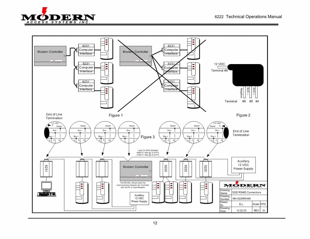
RS-485 Data Bus Conventions and Explanations The RS-485 data bus of the MASI Controller system is an encrypted, secure and proprietary communications bus conforming to EIA 1 pair RS-485 specifications. The data bus passes information between the various MASI peripheral equipment, including Card Reader Interfaces, Two Door Modules, Computer Interfaces, and Relay Expansion Boards. RS-485 Wiring The RS-485 data bus has some stringent requirements, which must be met in order to ensure signal performance and integrity. If your data bus length is less than 1000 feet, any 1 pair shielded cable is acceptable. Otherwise, a data bus of 1000 to 4000 feet must use a Low Capacitance (15pF per foot or less) 1 pair, shielded cable. Acceptable cables are Belden #8102, 8132, 9841, or equivalents. The data bus must be run from one device to the next in a serial or daisy-chain fashion, and not a star or split pattern (see Figure 1 on Page 12). The maximum length of the RS-485 cable must not exceed 4000 feet, and the two ends of the cable must have line termination packs (see Figure 2 on Page 12) installed on the terminals of the end peripheral devices. The RS-485 data bus is not sensitive to the positioning of devices within its maximum length. For example, the Controller is not necessarily at the end of the cable and may be found near the centre of its length (see Figure 3 on Page 12 for a diagram of sample system).
10

6222 Technical Operations Manual
Wiring Diagrams
11
6222 Technical Operations Manual
12