zs-6222 series usb-pio adapter
TRANSCRIPT

- 1 -
ZS-6222 Series USB-PIO Adapter
User’s Manual
Zip code: 183-0027
2-13-37, Honmachi, Fuchu, Tokyo, Japan
TEL: M81-(0)42-368-2126
FAX:M81-(0)42-364-0067
URL http://www.zenisu.co.jp/
- 2 -
◆ Table of contents ◆
1.Outline .................................................................................................................................. 3
2.Feature .................................................................................................................................. 3
3.Specification ........................................................................................................................ 3
3.1.Operation environment .................................................................................................... 3
3.2.USB ................................................................................................................................... 3
3.3.Parallel port ...................................................................................................................... 4
3.4.Product specification ........................................................................................................ 4
3.5.Appearance ....................................................................................................................... 4
4.Install .................................................................................................................................... 5
4.1.Download device driver .................................................................................................... 5
4.2.Windows Vista ................................................................................................................... 5
4.3.Windows XP/2000 ........................................................................................................... 12
5.Operation ............................................................................................................................ 17
5.1.Transfer data method ..................................................................................................... 17
5.2.Control signal .................................................................................................................. 18
5.3.I/O .................................................................................................................................... 19
5.4.Command chart .............................................................................................................. 20
5.4.1. R command .............................................................................................................. 20
5.4.2. W command ............................................................................................................. 20
5.4.3. T command ............................................................................................................ 211
5.4.4. C command .............................................................................................................. 21
5.4.5. D command .............................................................................................................. 21
5.4.6. P command .............................................................................................................. 21
5.4.7. L command .............................................................................................................. 21
6.Connector ........................................................................................................................... 22
7.Warranty ............................................................................................................................. 23
- 3 -
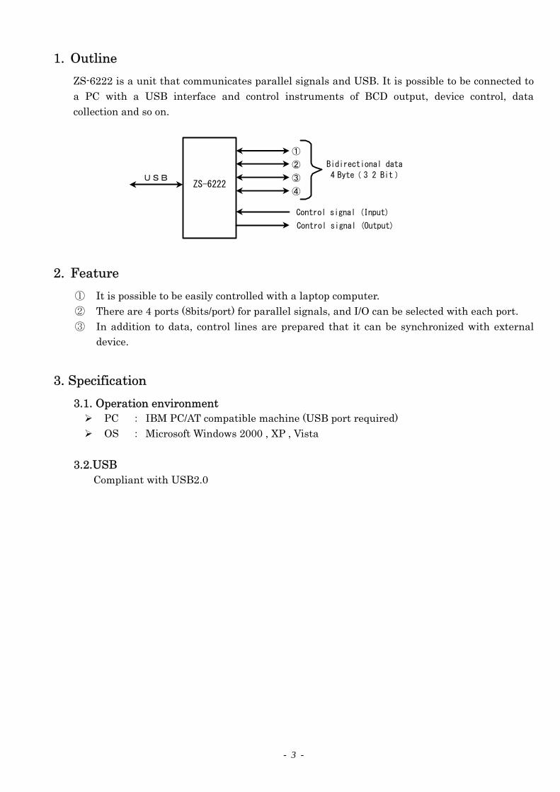
1. Outline
ZS-6222 is a unit that communicates parallel signals and USB. It is possible to be connected to
a PC with a USB interface and control instruments of BCD output, device control, data
collection and so on.
ZS-6222
①
②
③
④
Control signal (Input)
Control signal (Output)
USB
Bidirectional data
4 Byte( 3 2 Bit)
2. Feature
① It is possible to be easily controlled with a laptop computer.
② There are 4 ports (8bits/port) for parallel signals, and I/O can be selected with each port.
③ In addition to data, control lines are prepared that it can be synchronized with external
device.
3. Specification
3.1. Operation environment PC : IBM PC/AT compatible machine (USB port required)
OS : Microsoft Windows 2000 , XP , Vista
3.2.USB Compliant with USB2.0

- 4 -
3.3. Parallel port Port numbers : 4 port (8bit/port)
I/O level : Fan-in = 1
Fan-out = 10
Pull-up resistor 10KΩ, Pull-down is available
3.4. Product specification
Model ZS-6222P ZS-6222S
Feature Printed circuit type Small case built-in type
Data connector 50-coreflat cable 50-core flat cable
Power supply DC4.75V to 5.25V 100mA or less DC4.75V to 5.25V 100mA or less
Environment Tempreture0℃ to 50℃ Humidity85% or less Tempreture0℃ to 50℃ Humidity85% or less
Storage Temp -20℃ to 80℃ -20℃ to 80℃
Size 150×100×30H 150×100×30H
Accessary Data connector FAS-5001-2101-0BF Data connector FAS-5001-2101-0BF
DC power cable
3.5. Appearance
10KΩ
M5V or GHD
74AC245
ZS-6222 side
- 5 -
4. Install
4.1. Download device driver Please download the device driver corresponding to each OS from our website.
http://www.zenisu.co.jp
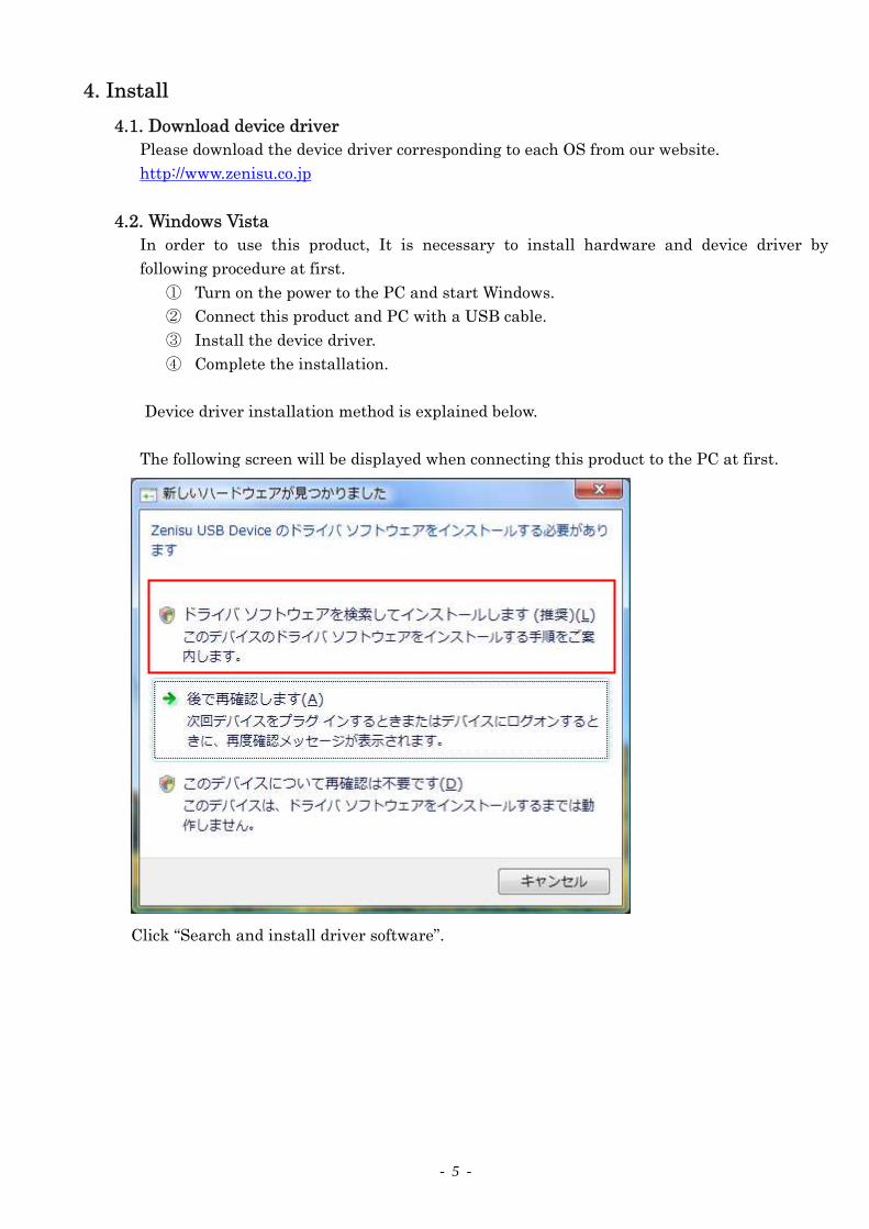
4.2. Windows Vista In order to use this product, It is necessary to install hardware and device driver by
following procedure at first.
① Turn on the power to the PC and start Windows.
② Connect this product and PC with a USB cable.
③ Install the device driver.
④ Complete the installation.
Device driver installation method is explained below.
The following screen will be displayed when connecting this product to the PC at first.
Click “Search and install driver software”.
- 6 -
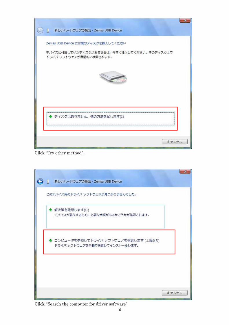
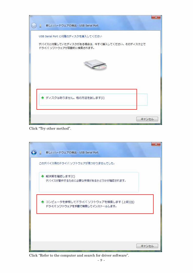
Click “Try other method”.
Click “Search the computer for driver software”.
- 7 -
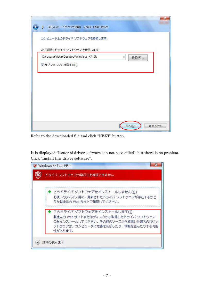
Refer to the downloaded file and click “HEXT” button.
It is displayed “Issuer of driver software can not be verified”, but there is no problem.
Click “Install this driver software”.

- 8 -
Click “Close” button.
The following screen will be displayed.
Click “Search and install driver software”.
- 9 -
Click “Try other method”.
Click “Refer to the computer and search for driver software”.

- 10 -
Refer to the downloaded file and click “HEXT” button.
It will be displayed but there is no problem.
Click “Install this driver software”.

- 11 -
Click “Close” button.

- 12 -
4.3. Windows XP/2000 In order to use this product, it is necessary to install hardware and device driver at first.
○1 Turn on the power to the PC and start Windows.
○2 Connect this product and PC with a USB cable.
○3 Install the device driver.
○4 Complete the installation.
Device driver installation method is explained below.
The following screen will be displayed when connecting this product to the PC at first.
Select “Install from a list or specific location” and click the “HEXT” button.

- 13 -
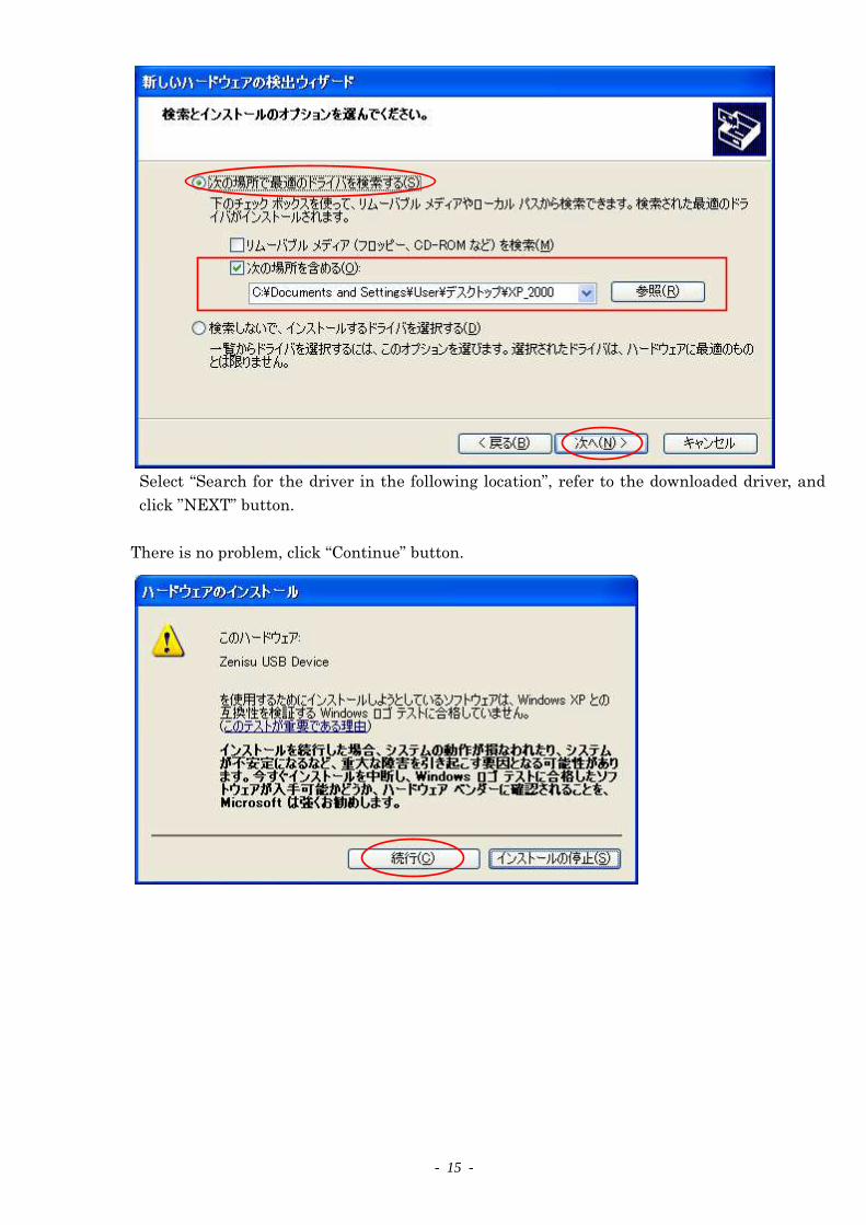
Select “Search for the driver in the following location”, refer to the downloaded driver, and
click ”HEXT” button.
The following screen will be displayed (Only for XP).
It is displayed “It has not passed Windows logo test to verify compatibility with Windows
XP”, but there is no problem. Click “Continue” button.

- 14 -
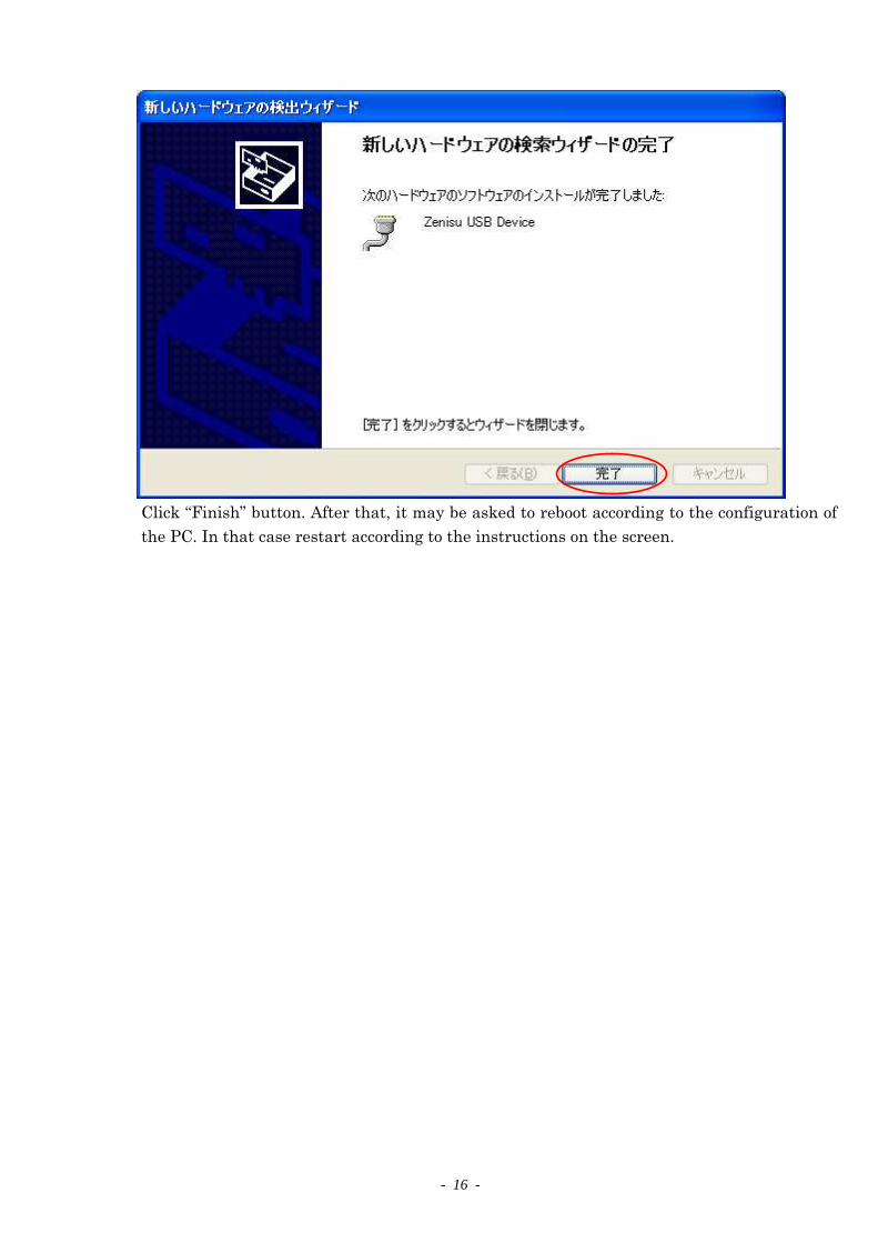
Click “Finish” button. After that, it may be asked to reboot according to the configuration of
the PC. In that case restart according to the instructions on the screen.
The following screen will be displayed.
Select “Install from the list or specific location” and click the “HEXT” button.
- 15 -
Select “Search for the driver in the following location”, refer to the downloaded driver, and
click ”HEXT” button.
There is no problem, click “Continue” button.
- 16 -
Click “Finish” button. After that, it may be asked to reboot according to the configuration of
the PC. In that case restart according to the instructions on the screen.

- 17 -
5. Operation
5.1. Transfer data method
① Communication of the ZS-6222 is executed with the COM port. “Zenisu USB Device
(COM x)” will be displayed in “Port(COM and LPT” column of the device manager of each
OS when install the device driver. “x” is a number and the value differs depending on the
personal computer. When creating a program, please open it according to the displayed
COM number.
② Data code
The data transfer method is used ASCII code, and one character is converted to 4-bit
parallel code.
4-bit parallel USB Data
8 4 2 1 HEX
0 0 0 0 0
0 0 0 1 1
0 0 1 0 2
0 0 1 1 3
0 1 0 0 4
0 1 0 1 5
0 1 1 0 6
0 1 1 1 7
1 0 0 0 8
1 0 0 1 9
1 0 1 0 A
1 0 1 1 B
1 1 0 0 C
1 1 0 1 D
1 1 1 0 E
1 1 1 1 F

- 18 -
③ The data sent from the PC is transferred sequentially from the small number of the port
for output. Port set for input is also sequentially taken from small number and sent to PC.
The data of each port is captured 4-bits at a time.
e.g) When ports 1 and 2 are set for input, and ports 3 and 4 are set for output.
Order to send to PC
Port data Order to output
to the ZS-6222 Port data
1 Port_1 D7 to D4 1 Port_3 D7 to D4
2 Port_1 D3 to D0 2 Port_3 D3 to D0
3 Port_2 D7 to D4 3 Port_4 D7 to D4
4 Port_2 D3 to D0 4 Port_4 D3 to D0
0000 0001D7 D0
0 1
0010 0011D7 D0
2 3
1010 1011D7 D0
A B
1100 1101D7 D0
C D
1
2
3
4
ZS-6222
Input
Output
0123
ABCDUSB
5.2. Control signal A control signal is displayed so that it can be synchronized with the connected device.
Signal Direction Description
STB OUT
ZS-6222 completes receiving all data from the PC and outputs a pulse signal
after parallel output.
External device can be used this signal for Latch-Clock.
TRG OUT A pulse signal is output to an external device by “T” command.
CLR OUT A pulse signal is output to an external device by “C” command.
It is possible to be used resetting external devices.
LAH IH When the latch circuit is enabled setting by “L” command, latch input data
with this signal. Input a signal with a pulse width of 500µs or more.
Hote) The pulse width of the output can be set by command.
It is possible to be set 10µs, 100µs and 1ms.

- 19 -
5.3. I/O ① Output data from PC to parallel port. After receiving the data sent from the PC, set the
data 4-bits at a time on the output port. When the data setting is completed, the STB
pulse is output.
Hote) When the amount of received data which is set to output port is exceeded, extra
data will be discarded.
If the received data is less than amount of setting data in an output port, the data
sent last time will be remained in the empty space.
Received data
1
3
2
4
Output port_3 High
Low
High
Low
Output port_4
STB output
1 2 3 4
② The data that is input from parallel port send to the PC.
Without latch
When ZS-6222 receives the “R” command from the PC, it takes in the data from the
input port and transmits it to PC.
With latch
Data from the input port is captured when the LAH input is LOW.
When ZS-6222 receives the “R” command from the PC, it sends the captured data to
the PC.
500μs or more
Input port
LAH signal
Received data
ABCD
R
A B C DTransmission
data
- 20 -
5.4. Command chart ZS-6222 recognizes the first byte of the data as a control command and control it.
It is necessary to add a delimiter (CRMLF) at the end of the data string and transmit.
If there is a character string other than the command at the beginning of the data, HG will be
sent as returned value.
Command Function
R Data is read from all ports set as input.
W Data is written to the port set as output.
T Pulse is output from the TRG signal.
C Pulse is output from the CLR signal.
D Configure port I/O settings.
P Set the pulse width of the control signal.
L Set the presence/absence of latch circuit.
5.4.1. R command Function
Data is read from all ports set as input.
e.g) If input port is set four ports, 8 bytes of data will be sent from ZS-6222 when
“R” command is used.
Format
R CR LF
Return value
xxxx・・・・CR LF: Amount of data as same as the number set for the input port will
be received.
X is an ASCII code from 0 to F.
HG CR LF: There is no input port.
5.4.2. W command Function
Write data to the port set as output and it is sent to ZS-6222.
If data is transmitted less than 8 bytes, the data will be newly changed for the
transmitted data and the previous data will be remained in empty space. If more
than 8 bytes of data are transmitted, it will be discarded.
Format
Wxxxx・・・・CR LF: Write output data to the output port after “W”.
x is an ASCII code from 0 to F.
Return value
OK CR LF: Data output complete to output port.
HG CR LF: Ho output port, data character error.
- 21 -
5.4.3. T command Function
Output the pulse to control signal “TRG”.
Format
T CR LF
Return value
OK CR LF: Pulse output is completed.
HG CR LF: Pulse output error.
5.4.4. C command Function
Output the pulse to control signal “CLR”.
Format
C CR LF
Return value
OK CR LF: Pulse output is completed.
HG CR LF: Pulse output error.
5.4.5. D command Function
Set the I/O of the four ports. All four ports are set to input when powering on the
ZS-6222.
Format
Dxxxx CR LF: Make setting in the order of port_1, port_2, port_3, and port_4 after
“D”. “x” is writes “I” for input, “O” for output.
Return value
OK CR LF: Setting is completed.
HG CR LF: Setting error, wrong character setting.
5.4.6. P command Function
The pulse width of the control signal “STB”, “TRG”, “CLR” can be set from 10µs,
100µs, 1ms. It is set to 10µs when powering on the ZS-6222.
Format
Px CR LF: “x” is 0 for 10µs, 1 for 100µs, 2 for 1ms.
Return value
OK CR LF: Setting is completed.
HG CR LF: Setting error, wrong character setting.
5.4.7. L command Function
It is possible to set the presence or absence of the latch circuit when inputting data.
It is set without latch circuit when powering on the ZS-6222.
Format
Lx CR LF: “x” is 0 for absence, 1 for presence.
- 22 -
Return value
OK CR LF: Setting is completed.
HG CR LF: Setting error, wrong character setting.
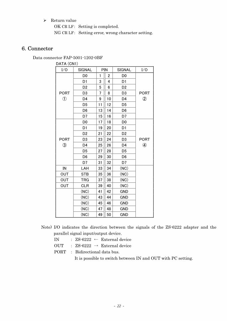
6. Connector
Data connector FAP-5001-1202-0BF
DATA (CN1)
I/O SIGNAL PIN SIGNAL I/O
D0 1 2 D0
D1 3 4 D1
D2 5 6 D2
PORT D3 7 8 D3 PORT
① D4 9 10 D4 ②
D5 11 12 D5
D6 13 14 D6
D7 15 16 D7
D0 17 18 D0
D1 19 20 D1
D2 21 22 D2
PORT D3 23 24 D3 PORT
③ D4 25 26 D4 ④
D5 27 28 D5
D6 29 30 D6
D7 31 32 D7
IN LAH 33 34 (NC)
OUT STB 35 36 (NC)
OUT TRG 37 38 (NC)
OUT CLR 39 40 (NC)
(NC) 41 42 GND
(NC) 43 44 GND
(NC) 45 46 GND
(NC) 47 48 GND
(NC) 49 50 GND
Hote) I/O indicates the direction between the signals of the ZS-6222 adapter and the
parallel signal input/output device.
IH : ZS-6222 ← External device
OUT : ZS-6222 → External device
PORT : Bidirectional data bus.
It is possible to switch between IH and OUT with PC setting.

- 23 -
7. Warranty
If it fails during normal use, we will repair it free of charge as described in this warranty as below.
1) During the warranty period which is one year from the date of purchase, we will
repair it free of charge in case of malfunction in accordance with instruction manual. 2) It will be charged for extra in the following case, even during warranty period.
Incorrect usage or failure or damage caused by carelessness. Failure or damage caused by improper repair or remodeling. Failure or damage caused by external factors such as fire, earthquake, other
natural disasters, abnormal voltage and so on. Replacement of consumable parts. Change of power supply and voltage.
3) This warranty provision is effective only in Japan