table of contents mk-3 navigation system meeknet.co · 3. mk-3 navigation. purpose of the system....
TRANSCRIPT
Initial Print Date:10/03/00 Revision Date:10/24/00
Subject Page
Purpose of the System. . . . . . . . . . . . . . . . . . . . . . . . . . . . . . . . . . . . . . .3
System Components
Navigation Computer. . . . . . . . . . . . . . . . . . . . . . . . . . . . . . . . . . . . . 4GPS Receiver. . . . . . . . . . . . . . . . . . . . . . . . . . . . . . . . . . . . . . . . . . . 5Gyro Sensor. . . . . . . . . . . . . . . . . . . . . . . . . . . . . . . . . . . . . . . . . . . . 5GPS Antenna. . . . . . . . . . . . . . . . . . . . . . . . . . . . . . . . . . . . . . . . . . . 6Display Units. . . . . . . . . . . . . . . . . . . . . . . . . . . . . . . . . . . . . . . . . . . 6Information/Body Bus Interface. . . . . . . . . . . . . . . . . . . . . . . . . . . . . . 7Video/Audio Signals. . . . . . . . . . . . . . . . . . . . . . . . . . . . . . . . . . . . . . 8Speed Signals. . . . . . . . . . . . . . . . . . . . . . . . . . . . . . . . . . . . . . . . . . 9Reverse Gear input.. . . . . . . . . . . . . . . . . . . . . . . . . . . . . . . . . . . . . . 9
Principle of operation. . . . . . . . . . . . . . . . . . . . . . . . . . . . . . . . . . . . . . . 10
Workshop Hints. . . . . . . . . . . . . . . . . . . . . . . . . . . . . . . . . . . . . . . . . . .12
Review Questions. . . . . . . . . . . . . . . . . . . . . . . . . . . . . . . . . . . . . . . . . 17
Table of Contents
Mk-3 NAVIGATION SYSTEM
2Mk-3 Navigation
Mk-3 NAVIGATION SYSTEM
Models: E38, E39, E46, E52, E53
Production Date: E46 from 6/00, all others from 9/00
Objectives
After completing this module you should be able to:
• Recognize the changes to Mk-3 from the previous Mk-2 navigation system.
• Identify the components used in the system.
• Review the operating fundamentals of GPS navigation.
• Describe how to properly code and program the Mk-3 computer.
3Mk-3 navigation
Purpose of the System
The Mk-3 navigation system is a factory installed navigation system that replaces the previous Mk-2 version. The purpose of the system remains the same as previous navigation systems: To provide the driver with navigation instructions to an entered destination based on the vehicles current position and the roads available selected from a digitized road map.
The principle differences of the Mk-3 system over the previous Mk-2 are:
• GPS receiver is integrated into the MK-3 computer.
• Optimized memory and faster processor resulting in faster start-up and operation.
• New split screen and magnifying feature when equipped with wide screen monitor.(software feature)
• Same navigation computer used for color board monitor or monochrome MIR display units.
4Mk-3 Navigation
System Components
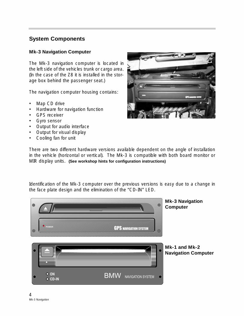
Mk-3 Navigation Computer
The Mk-3 navigation computer is located inthe left side of the vehicles trunk or cargo area.(In the case of the Z8 it is installed in the stor-age box behind the passenger seat.)
The navigation computer housing contains:
• Map CD drive• Hardware for navigation function• GPS receiver• Gyro sensor• Output for audio interface• Output for visual display• Cooling fan for unit
There are two different hardware versions available dependent on the angle of installationin the vehicle (horizontal or vertical). The Mk-3 is compatible with both board monitor orMIR display units. (See workshop hints for configuration instructions)
Identification of the Mk-3 computer over the previous versions is easy due to a change inthe face plate design and the elimination of the “CD-IN” LED.
Mk-3 NavigationComputer
Mk-1 and Mk-2Navigation Computer
POWER GPS NAVIGATION SYSTEM
ON
CD-INNAVIGATION SYSTEMBMW
5Mk-3 navigation
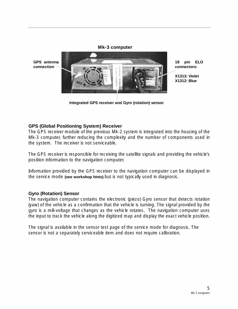
GPS (Global Positioning System) ReceiverThe GPS receiver module of the previous Mk-2 system is integrated into the housing of theMk-3 computer, further reducing the complexity and the number of components used inthe system. The receiver is not serviceable.
The GPS receiver is responsible for receiving the satellite signals and providing the vehicle’sposition information to the navigation computer.
Information provided by the GPS receiver to the navigation computer can be displayed inthe service mode (see workshop hints) but is not typically used in diagnosis.
Gyro (Rotation) SensorThe navigation computer contains the electronic (piezo) Gyro sensor that detects rotation(yaw) of the vehicle as a confirmation that the vehicle is turning. The signal provided by thegyro is a mili-voltage that changes as the vehicle rotates. The navigation computer usesthe input to track the vehicle along the digitized map and display the exact vehicle position.
The signal is available in the sensor test page of the service mode for diagnosis. The sensor is not a separately serviceable item and does not require calibration.
Mk-3 computer
GPS antennaconnection
18 pin ELOconnectors:
X1313: VioletX1312: Blue
Integrated GPS receiver and Gyro (rotation) sensor
6Mk-3 Navigation
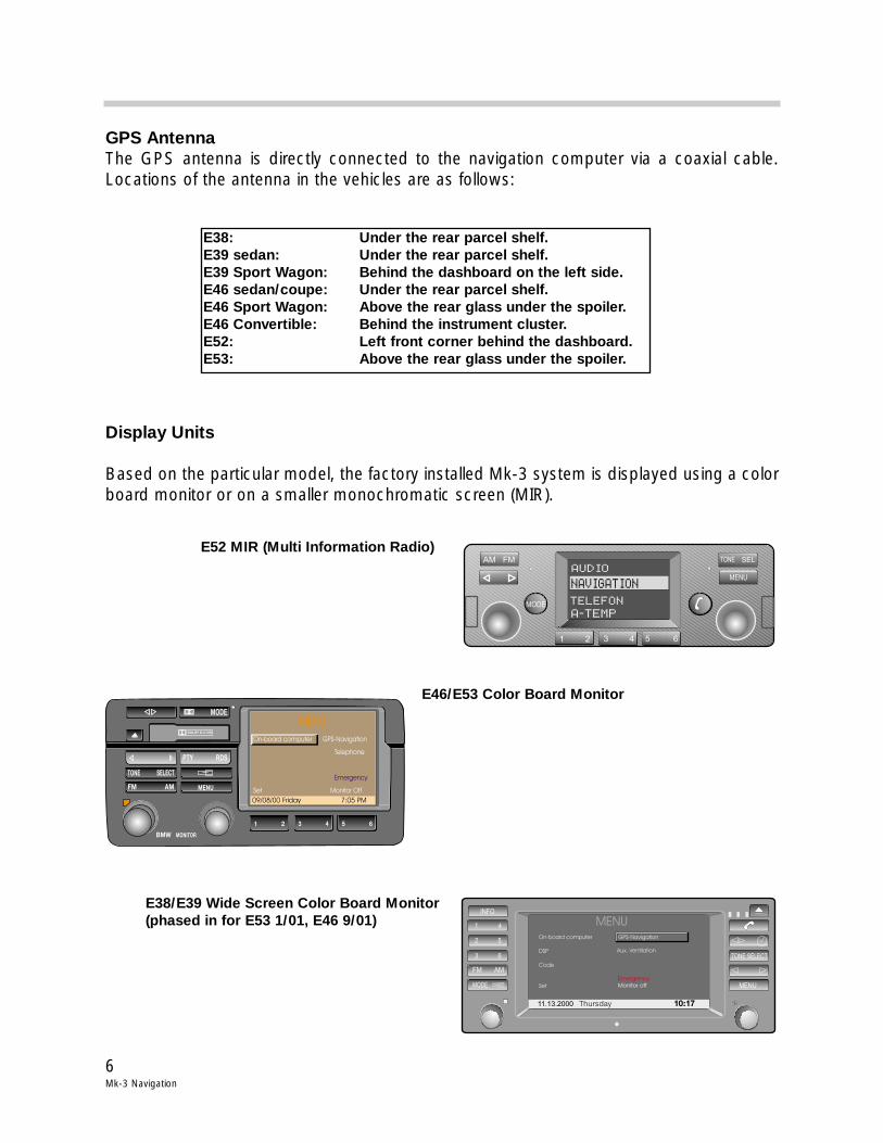
GPS AntennaThe GPS antenna is directly connected to the navigation computer via a coaxial cable.Locations of the antenna in the vehicles are as follows:
Display Units
Based on the particular model, the factory installed Mk-3 system is displayed using a colorboard monitor or on a smaller monochromatic screen (MIR).
AM FM
MODE
TONE SEL
MENU
1 2 3 4 5 6
AUDIO
NAVIGATION
TELEFON
A-TEMP
11.13.2000 Thursday 10:17
INFO
1 4
2 5
3 6
FM AM
MODE MENU
TONE SELECT
MENUOn-board computer
DSP
Code
Set
GPS-Navigation
Monitor off
Emergency
Aux. Ventilation
DOLBY B-C NR
1 2
BMW
3 4
MODE
5 6
TONE SELECT
FM AM
PTY RDS
MENU
MONITOR
09/08/00 Friday 7:05 PM
MENUOn-board computer
Telephone
onitor Off
GPS-Navigation
Set M
Emergency
E52 MIR (Multi Information Radio)
E46/E53 Color Board Monitor
E38/E39 Wide Screen Color Board Monitor(phased in for E53 1/01, E46 9/01)
E38: Under the rear parcel shelf.E39 sedan: Under the rear parcel shelf.E39 Sport Wagon: Behind the dashboard on the left side.E46 sedan/coupe: Under the rear parcel shelf.E46 Sport Wagon: Above the rear glass under the spoiler.E46 Convertible: Behind the instrument cluster.E52: Left front corner behind the dashboard.E53: Above the rear glass under the spoiler.
7Mk-3 navigation
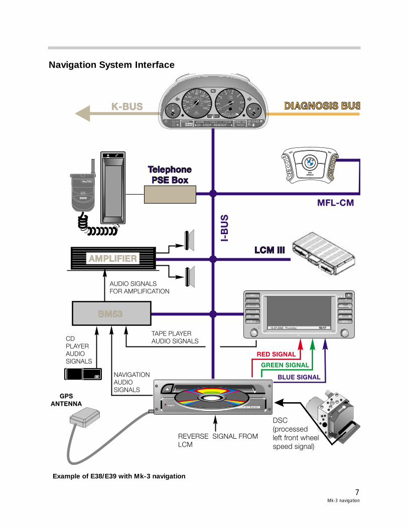
Navigation System Interface
RED SIGNAL
GREEN SIGNAL
BLUE SIGNAL
LCM IIILCM III
MFL-CM
Telephone
PSE Box
Telephone
PSE Box
I-B
US
K-BUS DIAGNOSIS BUSDIAGNOSIS BUS
SRS
AIRBAG
SRS
AIRBAG
BM W
BM53
NAVIGATION
AUDIO
SIGNALSGPS
ANTENNA
CD
PLAYER
AUDIO
SIGNALS
AUDIO SIGNALS
FOR AMPLIFICATION
TAPE PLAYER
AUDIO SIGNALS
AMPLIFIER
DSC
(processed
left front wheel
speed signal)
REVERSE SIGNAL FROM
LCM
POWER GPS NAVIGATION SYSTEM
13.07.2000 Thursday 10:17
INFO
1 4
2 5
3 6
FM AM
MODE MENU
TONE SELECT
BOSCH
0
½
CHECK
ENGINE
CHECK
ENGINE
OIL SERVICEOIL SERVICE
INSPECTION
P
1/minx 1000
km/h
ELECTRONIC
MPH
1
2020
4040
60
60
80
80
100
180160
140120100
200 120220
140
240
0
2
3 45
6
7
!
! ABS
20 DIGIT READOUT
123456 PRND SM
54321
122 4 72 0Fmiles
0101520
40
+
BMW
StarTAC
Example of E38/E39 with Mk-3 navigation
8Mk-3 Navigation
Information/body bus InterfaceThe navigation computer is integrated into the vehicle bus system as it’s main communica-tion link with the vehicle.
Communication occurs with the following modules:
• BMBT - Control inputs• Radio - Display data• GM - Door open• IKE/Kombi - On-board computer data• Telephone PSE Box - Monitor display data, mayday function • DISplus - Coding data
PSE = Portable Support Electronics
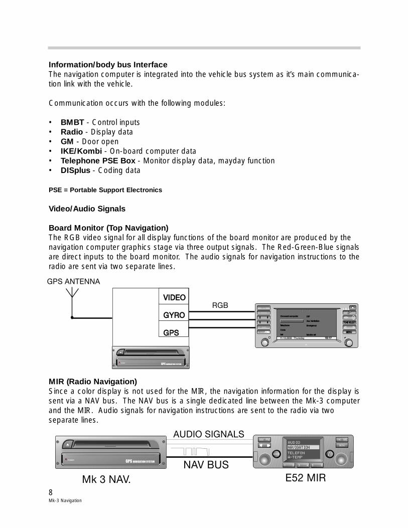
Video/Audio Signals
Board Monitor (Top Navigation)The RGB video signal for all display functions of the board monitor are produced by the navigation computer graphics stage via three output signals. The Red-Green-Blue signalsare direct inputs to the board monitor. The audio signals for navigation instructions to theradio are sent via two separate lines.
MIR (Radio Navigation)Since a color display is not used for the MIR, the navigation information for the display issent via a NAV bus. The NAV bus is a single dedicated line between the Mk-3 computerand the MIR. Audio signals for navigation instructions are sent to the radio via two separate lines.
AM FM
MODE
TONE SEL
MENU
1 2 3 4 5 6
AUDIO
NAVIGATION
TELEFON
A-TEMPPOWER GPS NAVIGATION SYSTEM
E52 MIRMk 3 NAV.
NAV BUS
AUDIO SIGNALS
11.13.2000 Thursday 10:17
INFO
1 4
2 52 5
3 63 6
FM AM
MODE MENUMENU
TONE SELECTTONE SELECT
MENUOn-board computer
Telephone
Code
Set
On-board computer
Telephone
Code
Set
GPS-Navigation
DSP
Aux. Ventilation
Emergency
Monitor off
DSP
Aux. Ventilation
Emergency
Monitor off
RGB
POWER GPS NAVIGATION SYSTEM
VIDEO
GYRO
GPS
VIDEO
GYRO
GPS
GPS ANTENNA
9Mk-3 navigation
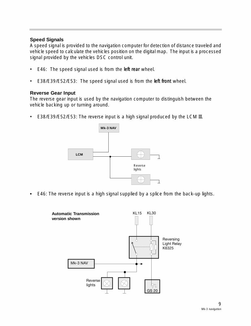
Speed SignalsA speed signal is provided to the navigation computer for detection of distance traveled andvehicle speed to calculate the vehicles position on the digital map. The input is a processedsignal provided by the vehicles DSC control unit.
• E46: The speed signal used is from the lleefftt rreeaarr wheel.
• E38/E39/E52/E53: The speed signal used is from the lleefftt ffrroonntt wheel.
Reverse Gear InputThe reverse gear input is used by the navigation computer to distinguish between the vehicle backing up or turning around.
• E38/E39/E52/E53: The reverse input is a high signal produced by the LCM III.
• E46: The reverse input is a high signal supplied by a splice from the back-up lights.
Mk-3 NAV
GS 20
Reverselights
ReversingLight RelayK6325
KL15 KL30
LCM
Mk-3 NAV
Reverselights
Automatic Transmissionversion shown
10Mk-3 Navigation
Principle of Operation
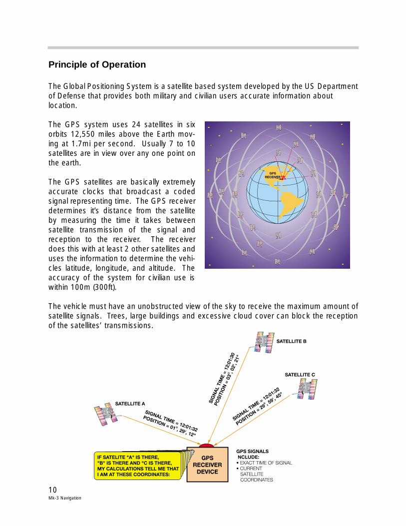
The Global Positioning System is a satellite based system developed by the US Departmentof Defense that provides both military and civilian users accurate information about location.
The GPS system uses 24 satellites in sixorbits 12,550 miles above the Earth mov-ing at 1.7mi per second. Usually 7 to 10satellites are in view over any one point onthe earth.
The GPS satellites are basically extremelyaccurate clocks that broadcast a codedsignal representing time. The GPS receiverdetermines it’s distance from the satelliteby measuring the time it takes betweensatellite transmission of the signal andreception to the receiver. The receiverdoes this with at least 2 other satellites anduses the information to determine the vehi-cles latitude, longitude, and altitude. Theaccuracy of the system for civilian use iswithin 100m (300ft).
The vehicle must have an unobstructed view of the sky to receive the maximum amount ofsatellite signals. Trees, large buildings and excessive cloud cover can block the receptionof the satellites’ transmissions.
11Mk-3 navigation
The GPS antenna passes the signal to the GPS receiver incorporated in the navigationcomputer. A CD with map data is loaded in the CD drive of the navigation computer. Thenavigation computer combines the vehicle position calculated by the GPS with this mapdata.
The current position of the vehicle can be shown on the on-board monitor by selecting“Emergency” from the main menu.
The driver can enter a destination. The navigation computer calculates a route from thecurrent location to this destination based on selectable criteria (main use of highways,shortest distance, etc.). The calculated route is shown in the route display.
The navigation computer generates the RGB color video signal for all on-board monitordisplays. These three signals are sent over separate shielded wires to the on-board mon-itor.
In the case of the E52 MIR (also referred as radio navigation) which does not have a colordisplay, the visual display data is sent via one wire called the navigation bus. On both sys-tems, color and monochrome display, the audio output from the navigation computer forvoice directions is sent over two separate wires.
The driver has the choice of displays that utilize a color map with an icon of the vehiclebeing traced on the map or the use of arrow indicators and distance data shown on theon-board monitor display. Vehicles equipped with the wide screen board monitor have asplit screen option that includes both display methods. The MIR only makes use of thearrows and distance display. With the assistance of voice prompts, the navigation computer indicates how and where to get into the correct lane or turn off.
The navigation computer calculates the distance traveled from the wheel speed signal delivered by the DSC control unit.
The gyro incorporated into the navigation computer housing informs the navigation com-puter when the vehicle is turning. An alternative route is re-calculated automatically if thedriver does not follow the original route instructions.
Once the driver has reached their destination, the navigation computer is ready for another destination input.
Refer to the on-board monitor owners manual for instructions on using the navigation system software.
12Mk-3 Navigation
Workshop Hints
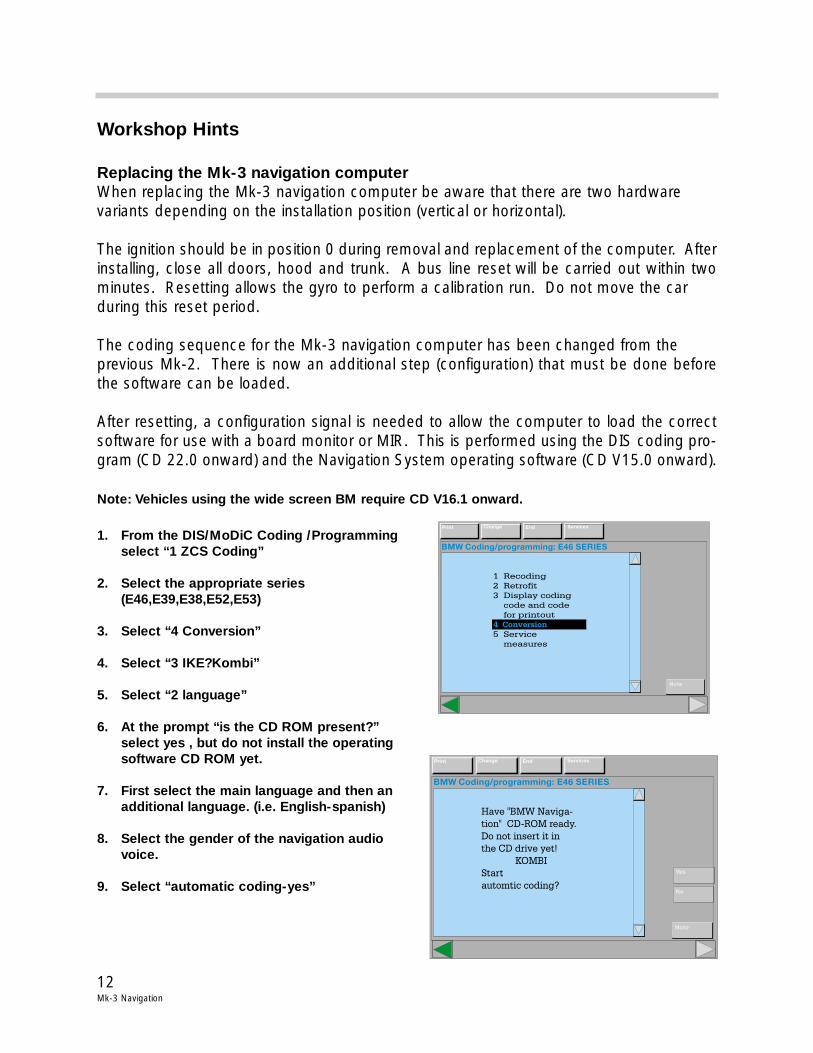
Replacing the Mk-3 navigation computerWhen replacing the Mk-3 navigation computer be aware that there are two hardware variants depending on the installation position (vertical or horizontal).
The ignition should be in position 0 during removal and replacement of the computer. Afterinstalling, close all doors, hood and trunk. A bus line reset will be carried out within twominutes. Resetting allows the gyro to perform a calibration run. Do not move the car during this reset period.
The coding sequence for the Mk-3 navigation computer has been changed from the previous Mk-2. There is now an additional step (configuration) that must be done beforethe software can be loaded.
After resetting, a configuration signal is needed to allow the computer to load the correctsoftware for use with a board monitor or MIR. This is performed using the DIS coding pro-gram (CD 22.0 onward) and the Navigation System operating software (CD V15.0 onward).
Note: Vehicles using the wide screen BM require CD V16.1 onward.
1. From the DIS/MoDiC Coding /Programming select “1 ZCS Coding”
2. Select the appropriate series (E46,E39,E38,E52,E53)
3. Select “4 Conversion”
4. Select “3 IKE?Kombi”
5. Select “2 language”
6. At the prompt “is the CD ROM present?” select yes , but do not install the operating software CD ROM yet.
7. First select the main language and then an additional language. (i.e. English-spanish)
8. Select the gender of the navigation audio voice.
9. Select “automatic coding-yes”
BMW Coding/programming: E46 SERIES
1 Recoding
2 Retrofit
3 Display coding
code and code
for printout
5 Service
measures
4 Conversion4
Print Change End Services
Note
4 Conversion
BMW Coding/programming: E46 SERIES
Print Change End Services
Note
Have "BMW Naviga-
tion" CD-ROM ready.
Do not insert it in
the CD drive yet!
KOMBI
Start
automtic coding?
Yes
No
13Mk-3 navigation
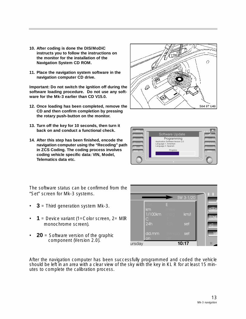
10. After coding is done the DIS/MoDiC instructs you to follow the instructions on the monitor for the installation of the Navigation System CD ROM.
11. Place the navigation system software in the navigation computer CD drive.
Important: Do not switch the ignition off during thesoftware loading procedure. Do not use any soft-ware for the Mk-3 earlier than CD V15.0.
12. Once loading has been completed, remove theCD and then confirm completion by pressing the rotary push-button on the monitor.
13. Turn off the key for 10 seconds, then turn it back on and conduct a functional check.
14. After this step has been finished, encode the navigation computer using the “Recoding” pathin ZCS Coding. The coding process involves coding vehicle specific data: VIN, Model, Telematics data etc.
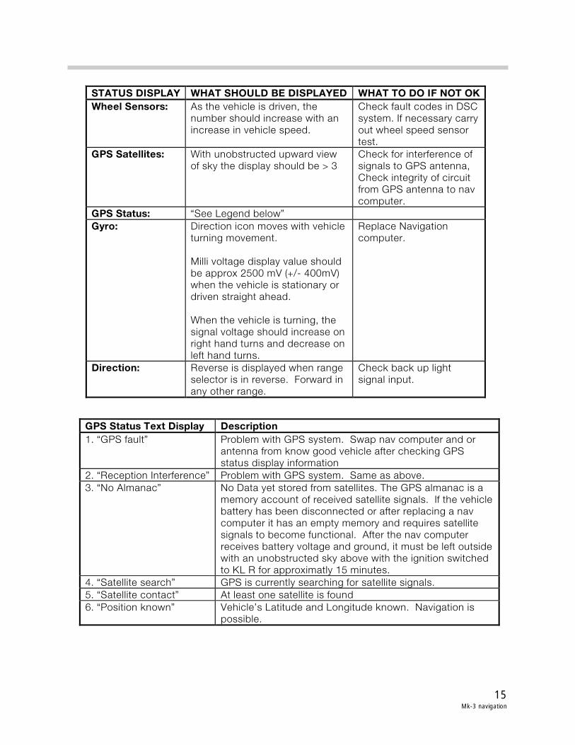
The software status can be confirmed from the“Set” screen for Mk-3 systems.
• 3 = Third generation system Mk-3.
• 1 = Device variant (1=Color screen, 2= MIRmonochrome screen).
• 20 = Software version of the graphic component (Version 2.0).
After the navigation computer has been successfully programmed and coded the vehicleshould be left in an area with a clear view of the sky with the key in KL R for at least 15 min-utes to complete the calibration process.
INFO
1 4
2 5
3 6
FM AM
MODE MENU
TONE SELECT
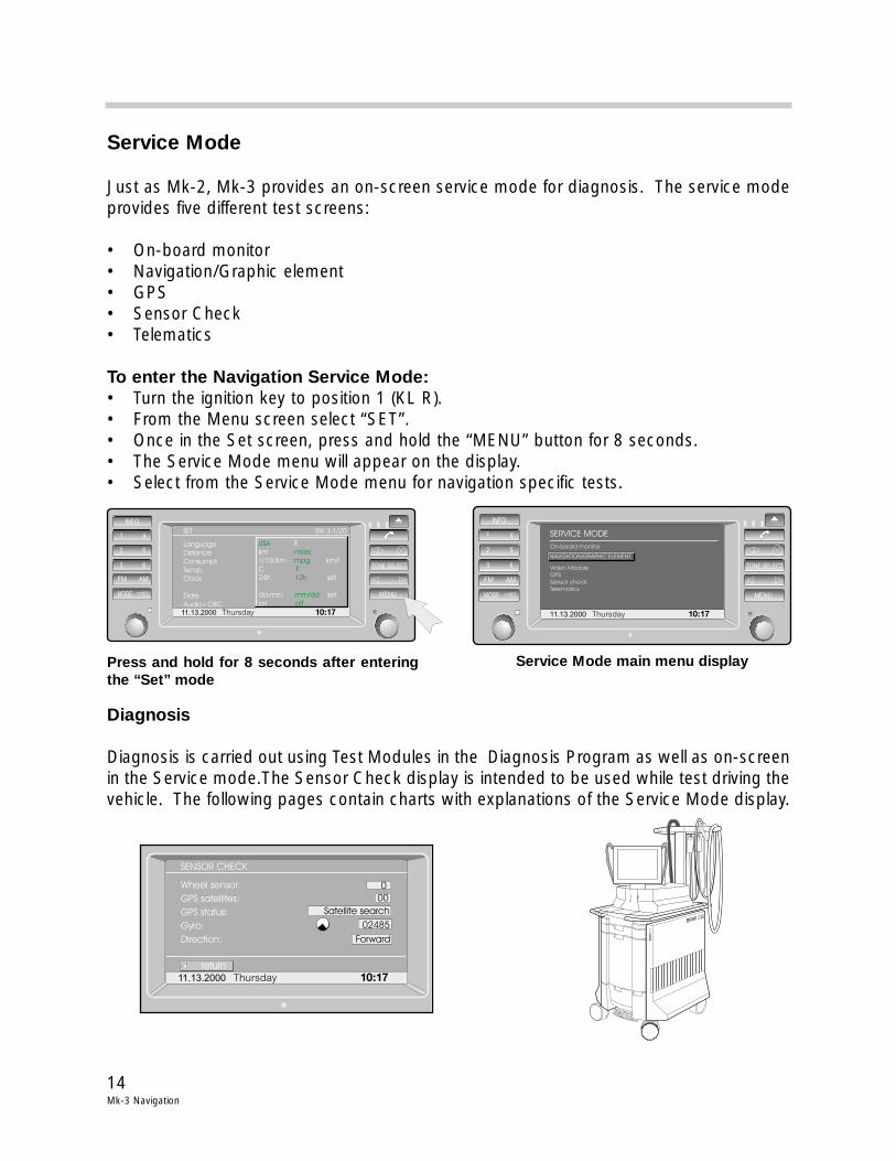
Software Update
ProgrammingApplication Software Version 2.0
Language 1: Amerikan
Language 2: Spanish
Progress
������ �����
�
������������������������
�� ���� !!
������������"���������������� �##������ �� �������������������$������������� ���������
����������� ���� ��������������
�%�&'� �#
14Mk-3 Navigation
Service Mode
Just as Mk-2, Mk-3 provides an on-screen service mode for diagnosis. The service modeprovides five different test screens:
• On-board monitor• Navigation/Graphic element• GPS• Sensor Check• Telematics
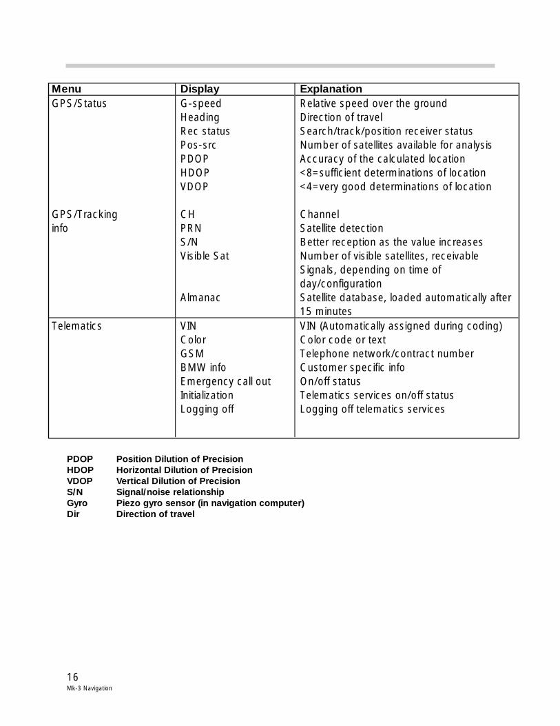
To enter the Navigation Service Mode:• Turn the ignition key to position 1 (KL R).• From the Menu screen select “SET”.• Once in the Set screen, press and hold the “MENU” button for 8 seconds.• The Service Mode menu will appear on the display.• Select from the Service Mode menu for navigation specific tests.
Diagnosis
Diagnosis is carried out using Test Modules in the Diagnosis Program as well as on-screenin the Service mode.The Sensor Check display is intended to be used while test driving thevehicle. The following pages contain charts with explanations of the Service Mode display.
11.13.2000 Thursday 10:17
INFO
1 4
2 5
3 6
FM AM
MODE MENU
TONE SELECT
Language
Distance
Consumpt.
Temp.
Clock
Date
Audio+OBC
USA
miles
mpg
F
12h
mm/dd
off
E
km
1/100km km/l
C
24h set
dd.mm set
on
SW 3-1/20SET
11.13.2000 Thursday 10:17
INFO
1 4
2 5
3 6
FM AM
MODE MENU
TONE SELECT
On-board monitor
Video Module
GPS
Sensor check
Telematics
NAVIGATION/GRAPHIC ELEMENT
SERVICE MODE
Press and hold for 8 seconds after enteringthe “Set” mode
Service Mode main menu display
BM
WD
IS
BMW DIS
BM
WD
ISB
MW
DIS
11.13.2000 Thursday 10:17
Wheel sensor:
GPS satellites:
GPS status:
Gyro:
Direction:
SENSOR CHECK
return
0
00
Satellite search
02485
Forward
15Mk-3 navigation
��������� �� �������� ����� ��� ��������������������������� ���� ����������� ������
������������������������������������ ������������
�������������������������������������������������������������������
����� ���! ��� ���������������������� �������������������������� !
������������������������"������#$������������������"�����������������#$������������ ���������
���� � "�� %���&�"��������' �#��� ��������������� ������ ������
������"�� ������(���� ����"�������� �����������������)*+,,�-./012,,�-3������� ����������������������� �������"��������������� ��������������"������"��� ����"�������������������"��������������������������������������
4������5� �"��������������
!��$ !��� 4� ����������������������"��������������� �����6�������������������"��
�������������"����"���������
���� � "���% !�&��# ��$�!& !��7�%#$������' $����������#$�������������� �������������
���������������"��� ������������������"#$�������������������������
*�%4��������������������' $����������#$����������������� ��!�%5�������' 5��������������������������������#$�����������
�������������������� �������������"���������� �����������������������������������������������"��� �������������������������������8����������������"�������������������������������� ������������� ��������� ����"����"������������������������������������������������� ���������"����������������9&4��������)������7+��������
2�%���������������' #$��������������������"��������������"�����+�%����������������' �������������������������:�%$������������' -������;�&����������&��"�����������5� �"�������
���������
16Mk-3 Navigation
PDOP Position Dilution of PrecisionHDOP Horizontal Dilution of PrecisionVDOP Vertical Dilution of PrecisionS/N Signal/noise relationshipGyro Piezo gyro sensor (in navigation computer)Dir Direction of travel
Menu Display Explanation GPS/Status GPS/Tracking info
G-speed Heading Rec status Pos-src PDOP HDOP VDOP CH PRN S/N Visible Sat Almanac
Relative speed over the ground Direction of travel Search/track/position receiver status Number of satellites available for analysis Accuracy of the calculated location <8=sufficient determinations of location <4=very good determinations of location Channel Satellite detection Better reception as the value increases Number of visible satellites, receivable Signals, depending on time of day/configuration Satellite database, loaded automatically after 15 minutes
Telematics VIN Color GSM BMW info Emergency call out Initialization Logging off
VIN (Automatically assigned during coding) Color code or text Telephone network/contract number Customer specific info On/off status Telematics services on/off status Logging off telematics services

17Mk-3 navigation
Review Questions
1. List the most signoficant changes made to the Mk-3 navigation computer over the previous Mk-2.
2. How can the signal provided by the gyro sensor to the navigation computer be checked?
3. Describe how the display signals are transmitted from the navigation computer to the MIR and board monitor.
4. What step is necessary before loading the navigation computer operating software CDon a newly replaced navigation computer? Where can the software status be confirmedafter it has been loaded?
5. How is the VIN entered into the navigation computer?