2016-07-12 industry specification master - union pacificuprr/@customers/@industrial... · preface...
TRANSCRIPT

1
Preface The following information is provided to help guide you through the planning and construction process of developing a rail-served facility. Union Pacific is committed to working with you to develop the most efficient, cost-effective rail plan to meet your transportation needs. The time required for rail spur construction depends largely on the magnitude of your project; averages presented below represent typical situations. Additional time may be necessary if your project involves road crossings, utilities or requires State permitting approval.
Track construction without addition of a Union Pacific turnout averages eleven (11) months. Addition of a Union Pacific turnout averages fifteen (15) months. Addition of a Union Pacific turnout and signal facilities averages seventeen (17) months.
This technical manual, “Checklist for Industry Track Submittals”, sample plan exhibits and UPRR’s Standard Drawings are revised periodically. It is the responsibility of the user to update his/her copy with the most current information. If you have any questions concerning this guideline or require further assistance, please contact the appropriate Manager-Industry and Public Projects (MIPP) A list of MIPP’S for each region can be found on the following web site: http://www.up.com/real_estate/roadxing/mipps/index.htm

2
NEW TRACK CONSTRUCTION OVERVIEW Procedures for Development of Track Plans The first step is for the customer to submit the Service Feasibility Questionnaire. This provides Union Pacific with the information necessary to evaluate your proposed project. If the customer is unable to process this online form, please contact the appropriate Marketing and Sales representative for assistance. If the customer has not already done so, the customer will need to select a qualified rail engineering consultant for the project. A list of consultants with experience in railroad construction projects is available for customer review at the following web site:
http://www.up.com/customers/ind-dev/contractor-list_construction/index.htm Please note this list is only a compilation of available vendors, not a list of approved or endorsed vendors. Union Pacific makes no representation as to the qualifications or expertise of any of the vendors listed. To begin the Location Analysis phase, the Regional Manager of Industrial Development (RMID) will contact the Customer to evaluate the proposed project, review Union Pacific’s Industry Access Guidelines and establish an on-site meeting plan. If the customer has a consultant on board at the time of the on-site meeting, the consultant should attend the meeting with the customer. The Manager of Industrial and Public Projects (MIPP) and representatives from UPRR’s local operating, maintenance, and signal departments should also attend the on-site meeting. At this meeting, the project site will be reviewed, field data will be collected and UPRR’s design requirements will be explained to the Customer. Track layout will be discussed along with operating, maintenance and signal issues and recommendations. The MIPP will provide the Customer with a Milepost (MP) and engineering station (ES) tie in point to help the Customer’s consultant establish MP and ES ties to switches and other required locations on their drawings. Drawings of Proposed Track Plans All of the required plan sets (10% Concept Plan, 30% Track Plan, Construction Drawings and Exhibit ‘A’ Print) are to be submitted to UPRR through UPRR’s Engineering Document Exchange System (EDS) website. After review and approval by the UPRR Engineering Dept, the plans will be distributed to other UPRR departments for review/approval as needed. It is important that the Customer, or Customer’s consultant, submit documents into the proper queue (10% Concept Plan, 30% Track Plan, etc.) in the EDS system - failure to do so may result in project delays . After all design issues are resolved, the EDS system will send notification of approval for each document to the Customer via the email address provided by the Customer. Following is the address of UPRR’s EDS Website:
http://www.up.com/customers/ind-dev/document_exchange/index.htm Following the onsite meeting, the Customer, or Customer’s consultant, will prepare a 10% Concept Plan (see Section 2.01 below) for review and approval.

3
If the project’s 10% Concept Plan receives UPRR’s inter-departmental approval and the project will involve modifying UPRR’s signal facilities, the Customer or Customer’s consultant will prepare and submit a 30% Track Plan (see Section 2.02 below) for review and approval. This step in the process will allow signal design to begin. UP’s Signal Department will do all signal design work. Regardless of whether signal work is involved and dependant on UPRR inter-departmental approval, the Customer, or Customer’s consultant, will prepare and submit a detailed and complete set of Construction plans for the proposed project (see Section 2.03 below) for review and approval. The Customer or Customer’s consultant will also need to prepare and submit an Exhibit ‘A’ print (see Section 2.04 below) for review and approval. The Exhibit ‘A’ print is a legally binding document that will be inserted into the Industrial Track Agreement (ITA). Any other documents submitted (pictures, construction schedules, reports, etc.) are to be loaded into the “Other” category in the EDS. Comment section should note the type of document being loaded. After all design issues are resolved and the project documents have been approved, a cost estimate will be generated and both parties will sign an Industry Track Agreement (ITA). Construction Guidelines Prior to performing any track construction on Union Pacific property, the following must occur:
a) A fully executed Industry Track Agreement (ITA) is in effect.
b) The designated Railroad representative must be notified in writing at least fifteen working days prior to start of construction so that appropriate safety precautions may be taken. Any flagging protection provided by Union Pacific will be at customer’s expense.
c) Union Pacific's Telecommunications Operation Center must be contacted at 1-800-336-9193 for
fiber optic information prior to track construction on Union Pacific property. The Contractor is also responsible for securing dig permits for any other utility work within the work limits from the appropriate call before you dig service.
The industrial track(s) must be constructed per approved plans; written approval for any changes must be obtained prior to construction. The rail contractor must abide by the Minimum Safety Requirements for Customer Contractors Entering Railroad Property set forth in Section 1.00. Upon completion of the entire rail project, the MIPP must be contacted for inspection and final approval of all grading and track work. On the rare occasion that the actual track construction differs from the originally approved design, the Railroad may request "as built" drawings of the industrial track from the customer. The “as built” drawings will show the corrected stationing, geometry, structures and clearances. The Industry Track Agreement will then be amended if necessary. Costs Associated with Track Construction All design, engineering, and construction are at the Customer's expense, including flagging protection. Grading construction includes overhead or underground utility adjustments, the installation of drainage facilities or structures under or along the proposed track(s), clearing, grubbing, any required fill or excavation, compaction, stabilization, and placement of subballast both on and off Union Pacific
4
property. Private track construction will include but is not limited to rail, ties, ballast, turnouts, road crossings, miscellaneous track material and labor. Signal Work for Track Connection Any signal work associated with connecting a new industry track to an existing Union Pacific owned track will be constructed by Union Pacific labor forces, at the Customer’s expense. If the portion of track owned and operated by the Customer crosses public streets, all signal construction and maintenance work will be completed by the Customer per Union Pacific Railroad specifications and American Railway Engineering and Maintenance-of-Way (AREMA) guidelines. Road Crossings As a general policy, Union Pacific prohibits the construction of new public or private roadways across its tracks. If a project requires the construction of a new grade crossing across Union Pacific owned or operated tracks, written approval will be required from Union Pacific management and any applicable State Regulatory Agency. If approved, a separate crossing agreement will be required. The industry will be responsible for obtaining all permits. Crossings may require the installation of automated crossing signals. All costs for both the crossing surfaces and signals will be at the customer’s expense. Portion of Track to be Constructed by Union Pacific Typically, Union Pacific constructs, owns, and maintains the connection to any existing Union Pacific owned tracks from the switch connection (point of switch) to the 13-foot clearance point. The 13 foot clearance point is defined as the point on the track where the centerline of two tracks are separated by 13 feet such that a rail car either being moved or stored on the track will not interfere with the movement of other rail cars on adjacent main, branch or lead tracks owned by Union Pacific. On projects where the turnout and derail are powered and connected to the signal system Union Pacific will construct, own and maintain to the point 50’ past the switch connection of the power operated derail. Materials For Track Construction All materials used for the construction of the proposed track must meet Union Pacific standards as outlined in Section 10.0. Union Pacific prefers that our customer have their rail contractor furnish Union Pacific’s track material. Once Union Pacific has approved the track design, a turnout with connecting rods, switch stand, and any other required track materials can be purchased from one of Union Pacific's approved vendors. The terms associated with the assembly and installation of this material will be outlined in the Industrial Track Agreement. Use of this option may be restricted depending on the location of the project and is subject to Union Pacific approval.

5
1.00 - MINIMUM SAFETY REQUIREMENTS FOR CUSTOMERS OR CONTRACTORS ENTERING UNION PACIFIC RAILROAD PROPERTY
1.01 GENERAL SAFETY - Safety of personnel, property, rail operations and the public is of paramount importance in the prosecution of the work pursuant to the project. As reinforcement and in furtherance of overall safety measures to be observed (and not by way of limitation), the following special safety rules shall be followed. The Industry shall keep the job site free from safety and health hazards and ensure that its employees are competent and adequately trained in all safety and health aspects of the job. The Industry shall have proper first aid supplies available on the job site so that prompt first aid services can be provided to any person that may be injured on the job site. The Industry shall promptly notify the Union Pacific Railroad (UP) of any U.S. Occupational Safety and Health Administration reportable injuries occurring to any person that may arise during the work performed on the job site. The Industry shall have a non-delegable duty to control its employees, while they are on the job site or any other property of the UP, to be certain they do not use, be under the influence of, or have in their possession any alcoholic beverage or illegally obtained drug, narcotic or other substance that may inhibit the safe performance of work by an employee. 1.02 ATTIRE AND PERSONAL PROTECTIVE EQUIPMENT - The employees of the Industry shall be suitably dressed to perform their duties safely and in a manner that will not interfere with their vision, hearing or free use of their hands or feet. Only waist length shirts with sleeves and trousers that cover the entire leg are to be worn. If flare-legged trousers are worn, the trouser bottoms must be tied to prevent catching. The employees should wear sturdy and protective footwear. Employees shall not wear boots (other than work boots), sandals, canvas-type shoes or other shoes that have thin soles or heels that are higher than normal. In addition, the Industry shall require its employees to wear personal protective equipment as specified by UP rules, regulations or UP officials overlooking the work at the job site. In particular, the protective equipment to be worn shall be:
a) Protective headgear that meets American National Standard-Z89.1-latest revision, it is suggested that all hardhats be affixed with Industry’s or industry’s contractor's company logo or name.
b) Eye protection that meets American National Standard for occupational and educational eye
and face protection, Z87.1-latest revision. Additional eye protection must be provided to meet specific job situations such as welding, grinding, burning, etc.
c) Hearing protection which affords enough attenuation to give protection from noise levels that
will be occurring on the job site. 1.03 EQUIPMENT - All heavy equipment provided or leased by the Industry shall be equipped with audible backup warning devices. If in the opinion of the UP representative any of the Industry's, or any of it’s subcontractors equipment, is unsafe for use on the UP's right-of-way, the Industry, at the request of the UP representative, shall remove such equipment from the UP’s right-of-way.

6
2.00 - REQUIRED INFORMATION TO BE SHOWN ON SUBMITTALS These requirements cover the following submittals: 1.) 10% design print submittal: After the initial onsite meeting with the Regional Manager of Industrial Development (RMID) and the Manager of Industry and Public Projects (MIPP) this “plan view only” print can be developed using the information collected at the onsite meeting, property plats, aerial photos, UP valuation maps etc., without the need of a formal site survey. This 10% drawing shall be used by the Union Pacific Railroad (UP) to determine the feasibility of proceeding with the project.
2.) 30% design print submittal. This submittal is required only if the industry track project affects the UP’s signal system. The need for this step will be determined during the review process of the 10% design print. UP’s Signal Department will do all signal design work. 3.) Construction plans and specifications. These plans and specifications should include all plan and profile drawings, material specifications, design calculations, etc. required to gain the UP’s final approval and to construct the project. 4.) Exhibit ‘A’ print. This drawing is a simplified track plan that is included as an exhibit in the Industry Track Agreement (ITA). Because the ITA is a legally binding document, the Exhibit ‘A’ print must be accurate and easy to interpret. NOTE: The FES # must be identified on each of the plan submittals. Sample exhibits for the 10%, 30% and Exhibit “A” submittals along with the “Checklist for Industry Track Submittals” are located at the following web site: http://www.up.com/customers/ind-dev/operations/specs/track/index.htm These exhibits represent UPRR’s required format for each submittal and include information typically required for each submittal. To provide for uniformity and expedite the review process, it is important that all track plans submitted use the appropriate format, line styles, colors, etc. CAD files are available to assist the designer and include MicroStation seed files, sheet borders, etc. These files can be obtained by contacting the local MIPP.
7
2.01.00 - REQUIREMENTS FOR A 10% INDUSTRIAL TRACK DESIGN PRINT SUBMITTAL The sample 10% submittal print (see UP Exhibit ‘10% Design’ ) and the Industry Track Submittal Checklist (see UP Exhibit ‘A-1’) should be used as guidelines for preparing the 10% submittal. The preferred 10% submittal should show the proposed track layout information plotted on a scaled aerial photographic map. The aerial map background must be light enough so that any track arrangement drawn over it is visible on the required 11”x17” print. The following are minimum requirements. If additional information is deemed beneficial, that information should be included on this submittal as well.
2.01.01 TURNOUTS - Show all existing turnouts (within 1500’ of the limits of the construction area) and proposed turnouts, including size (No. 11, No. 15, etc). Show the Engineering Station (ES) of each point of switch. On all proposed single ended tracks, this shall be ES 0+00. If the proposed track is double ended, the turnout located closest to the UP’s lesser Milepost (MP) shall be designated as ES 0+00. Each point of switch in a UP track shall also be identified by UP’s ES and MP with a station equation for the proposed industry track (i.e., UPRR ES 23+42/MP 46.90 = ES 0+00 Track ‘A’). The MIPP can help you determine turnout sizes, ES and MP locations. 2.01.02 TRACKS - Show a plan view of all track arrangements including existing tracks, proposed tracks, and future tracks. All existing tracks are to be designated by their unique track identification, Zone Track Spot (ZTS) number; (the RMID or the MIPP can provide these track numbers). All proposed or future tracks should be designated as Track ‘A’, Track ‘B’, etc. On all proposed tracks, show the ES of the thirteen-foot (13’) clearance point, the ES of the derail (describe the type of derail), the ES of the point there the track centerline crosses UP R/W, if applicable, and the ES of the end of track (EOT), including the type of EOT device. On all proposed tracks, show the right-angled center to center distances between all tracks. In addition, note the ES of the “End of UPRR Maintenance” sign. Typically this is at the 13 ft. clearance point for a non-controlled/hand-thrown turnout. For powered turnouts/derails this point is located 50 ft. beyond the derail switch point. 2.01.03 TRACKS – PROPOSED SALE OR LEASE - Show any proposed sale or lease of an existing UP owned track (or portion thereof) that is required as part of the construction plan, including the ES for the beginning and end of the proposed sale or lease. 2.01.04 RIGHT OF WAY (R/W) - Show the existing UP R/W, if applicable, and the right-angled distance to the track the R/W is tied to. This information is shown on UP’s R/W maps. Use the appropriate UP R/W line style. 2.01.05 ROAD CROSSINGS - Show the ES/MP location of the centerline of all existing and proposed roads crossing UP tracks, the type of crossing material (concrete, wood, etc.), the length of crossing, type (public/private), and the type of crossing warning device. All road crossings within fifteen hundred feet (1500’) of a proposed turnout that has any type of electric warning device must be located and shown on the print. Be advised, if a new road crossing is proposed near an existing one, the crossing warning devices may have to be upgraded.

8
2.01.06 BUILDINGS - Show all existing and proposed buildings adjacent to any existing or proposed tracks, including any unloading doors, ramps, docks, etc. Show the right-angled distance from any track within fifty-foot (50’) of these buildings, doors, ramps, and docks, etc. 2.01.07 HORIZONTAL CURVES - Horizontal curves are defined using the 100-foot chord definition method. Show a short line perpendicular to the beginning/end of curve points. Show the Degree of Curve and the ES of these curve points (PC and PT). 2.01.08 OPERATING PLAN - Provide an explanation of the proposed operating plan for the project. Operating plan should include number of cars delivered and released and the proposed timing of these movements. Plan should also include any additional movements (if necessary) planned within the facility. Include any other details as necessary. This information will be used by UP’s Transportation Department to determine if your plan is workable with existing UP operations. 2.01.09 SCOPE OF WORK - Provide a Scope of Work showing work to be performed by the UP and the Industry. Specifically define turnouts to be installed and length of track to be constructed by UP. In addition, define all work to be done by the Industry. Total track footage of industry track to be built on UPRR right-of-way and the distance from mainline must be noted on the scope of work. 2.01.10 DRAWING STANDARDS - Plans should have the approved UP drawing border and use UP Standard Legend and Abbreviations Drawing (see UP Exhibit ‘GL001’ Drawing) as a guideline. Acceptable plan scale: 1” = 100’ or 1” = 200’in an 11”x17” Adobe Acrobat PDF format only. All pages constituting your 10% plan should be loaded as a single PDF file, with the exception that file size should not exceed 20 mg. If the file size exceeds 20 mg it should be split into pieces, not to exceed 20mg. Show a directional north arrow, subdivision name, track name/ZTS number , the Timetable direction of the track and the next timetable station in both directions. The MIPP can help with getting this information. Plan scale of 1” = 400’ is also acceptable for the 10% Plan only. 2.01.11 INDUSTRIAL TRACK STANDARDS CHECKLIST - Include the Checklist for Industry Track Submittals (Exhibit ‘A-1’) with the 10% submittal, complete with the Industry’s Name, Project Location, and the Design Firm’s Name, Address, and Phone Number. Also, include the FES # in the space provided. 2.01.12 ROADS OR ROADWAY MODIFICATIONS - Show all proposed access roads or roadway modifications etc. not crossing UP tracks that would affect the amount of traffic crossing UP tracks. Include location, width, and type of roadway surface.

9
2.02.00 - REQUIREMENTS FOR A 30% INDUSTRIAL TRACK DESIGN PRINT SUBMITTAL The 30% submittal (see UP Exhibit ‘30% Design ) is required only if the industry track project will impact UPRR’s signal system. The need for this step will be determined during the review process of the 10% design print. UP’s Signal Department will do all signal design work. Similar to the 10% design print, the 30% submittal should show the proposed track layout information plotted on a scaled aerial photographic map. The aerial map background must be light enough so that any track arrangement drawn over it is visible on the required 11”x17” print. After the 10% print approval, the process of preparing the design plans begins. The purpose of the 30% print is to establish the exact location of the turnout in UP’s track, at this point a signal design can begin. This “exact location” can be affected by a number of factors. Each project has its own particular circumstances that will affect the final turnout placement. If the location of a turnout in UP’s mainline has to be moved after the 30% Plan approval, the signal design will have to start over, causing delays and increased costs. Following is information needed by UP’s Signal Department to complete their design work. Some of this information will already be on the 10% submittal.
2.02.01 TURNOUTS - Show all existing turnouts (within 1500’ of the limits of the construction area) and proposed turnouts, including size (No. 11, No. 15, etc). Show the Engineering Station (ES) of each point of switch. On all proposed single ended tracks, this shall be ES 0+00. If the proposed track is double ended, the turnout located closest to the UP’s lesser Milepost (MP) shall be designated as ES 0+00. Each point of switch in a UP track shall be identified by UP’s ES and MP with a station equation for the proposed industry track (i.e., UPRR ES 23+42/MP 46.90 = ES 0+00 Track ‘A’). The MIPP can help you determine turnout sizes, ES, and MP locations. 2.02.02 TRACKS - Show a plan view of all track arrangements including existing tracks, proposed tracks, and future tracks. All existing tracks are to be designated by their unique track identification, Zone Track Spot (ZTS) number; (the RMID or the MIPP can provide these track numbers). All proposed or future tracks should be designated as Track ‘A’, Track ‘B’, etc. On all proposed tracks, show the ES of the thirteen-foot (13’) clearance point, the ES of the derail (describe the type of derail), the ES of the point where the track centerline crosses UP R/W, if applicable, and the ES of the end of track (EOT), including the type of EOT device. On all proposed tracks, show the right-angled center to center distances between all tracks. In addition, note the ES indicating placement of the “End of UPRR Maintenance” sign. Typically this is at the 13 ft. clearance point for a non-controlled/hand-thrown turnout. For powered turnouts/derails this point is located 50 ft. beyond the derail switch point. 2.02.03 TRACKS - PROPOSED SALE OR LEASE - Show any proposed sale or lease of an existing UP owned track (or portion thereof) that is required as part of the construction plan, including the ES for the beginning and end of the proposed sale or lease. 2.02.04 RIGHT OF WAY (R/W) - Show the existing UP R/W, if applicable, and the right-angled distance to the track the R/W is tied to. This information is shown on UP’s R/W maps.

10
2.02.05 ROAD CROSSINGS - Show the ES/MP location of the centerline of all existing and proposed roads crossing UP tracks, the type of crossing material (concrete, wood, etc.), the length of crossing, type (public/private), and the type of crossing warning device. All road crossings within fifteen hundred feet (1500’) of a proposed turnout that has any type of electric warning device must be located and shown on the print. Be advised, if a new road crossing is proposed near an existing one, the crossing warning devices may have to be upgraded. 2.02.06 BUILDINGS - Show all existing and proposed buildings adjacent to any existing or proposed tracks, including any unloading doors, ramps, docks, etc. Show the right-angled distance from any track within fifty-foot (50’) of these buildings, doors, ramps, docks, etc. 2.02.07 HORIZONTAL CURVES - Horizontal curves are defined using the 100-foot chord definition method. Show a short line perpendicular to the beginning/end of spiral and curve points. Show the Degree of Curve and the ES of these curve points. 2.02.08 OPERATING PLAN – The proposed operating plan is to be included ONLY on the 10% design submittal. An Operating Plan should not be included for this submittal. 2.02.09 SCOPE OF WORK - Provide a detailed Scope of Work showing work to be performed by the UP and the Industry. Specifically define turnouts to be installed and length of track to be constructed by UP. In addition, define all work to be done by the Industry. Total track footage of industry track to be built on UPRR right-of-way and the distance from mainline must be noted on the scope of work. 2.02.10 DRAWING STANDARDS - Plans should have the approved UP drawing border and use UP Standard Legend and Abbreviations Drawing (see UP Exhibit ‘GL001’ Drawing) as a guideline. Acceptable plan scale: 1” = 100’ or 1” = 200’ in an 11”x17” Adobe Acrobat PDF format only. All pages constituting your 30% plan should be loaded as a single PDF file, with the exception that file size should not exceed 20 mg. If the file size exceeds 20 mg it should be split into pieces, not to exceed 20mg. Show a directional north arrow, subdivision name, track name/ZTS number , the Timetable direction of the track and the next timetable station in both directions. The MIPP can help with getting this information. 2.02.11 INDUSTRIAL TRACK STANDARDS CHECKLIST - Include the Checklist for Industry Track Submittals (Exhibit ‘A-1’) with the 30% submittal, complete with the Industry’s Name, Project Location, and the Design Firm’s Name, Address, and Phone Number. Also, include the FES # in the space provided. 2.02.12 ROADS OR ROADWAY MODIFICATIONS - Show all proposed access roads or roadway modifications etc. not crossing UP tracks that would affect the amount of traffic crossing UP tracks. Include location, width, and type of roadway surface. 2.02.13 SIGNAL INFORMATION REQUIRED - Show all signal houses, bungalows, cases, etc. within fifteen hundred feet (1500’) of any proposed turnout. A minimum seven hundred fifty feet (750’) beyond the project limits must be shown on the 30% submittal, regardless of signal

11
facilities present. Show the location of any overhead or underground signal lines in the project area. The MIPP can help with getting the above signal information. 2.02.14 TRACKS (Additional Information) - On all tracks, show the total length, the ES of the thirteen-foot (13’) clearance point, the ES of the derail (describe the type of derail), the ES of the point there the track centerline crosses UP R/W (if applicable) and the ES of the EOT including the type of EOT device. Show the right-angled center to center distances between all tracks. 2.02.15 EXISTING AND PROPOSED TRACK PROFILE - Provide a top of rail profile of the proposed industry track and the UP’s existing track where the new turnout(s) will be installed. Maximum interval is one hundred foot (100’). The profile shall extend a minimum of two hundred feet (200’) ahead of the point of switch and two hundred feet (200’) behind the end of the long switch ties. For proposed vertical curves, refer to UP Std Dwg 0016. Provide ES and elevation information at vertical curve points (PVC, PVI and PVT). 2.02.16 UP STATIONING AND BENCHMARK - Provide a description and ES of the point that UP stationing was established from (existing turnout, bridge backwall, CL of road crossing, etc.); the MIPP can help with getting this information. Also provide a description and location of the benchmark used to establish elevations for the project. 2.02.17 CONSTRUCTION SCHEDULE - Provide a construction schedule showing planned duration of major activities along with a proposed phasing plan.

12
2.03.00 - REQUIRED INFORMATION TO BE SHOWN ON CONSTRUCTION PLANS The following information is to be provided on the complete construction plan set. Some of the following required information will already be shown on the 10% and 30% (if applicable) Industrial Track Design Prints. The sample Exhibit ‘A-1’ (see UP Exhibit ‘A-1’ Drawing) should be used as guideline for preparing the complete plan set. The use of aerial photographic imagery is not recommended for the complete construction plan set.
2.03.01 TURNOUTS - Show all existing turnouts (within 1500’ of the limits of the construction area) and proposed turnouts, including size (No. 11, No. 15, etc). Show the Engineering Station (ES) of each point of switch. On all proposed single ended tracks, this shall be ES 0+00. If the proposed track is double ended, the turnout located closest to the UP’s lesser Milepost (MP) shall be designated as ES 0+00. Each point of switch in a UP track shall also be identified by UP’s ES and MP with a station equation for the proposed industry track (i.e., UPRR ES 23+42/MP 46.90 = ES 0+00 Track ‘A’). The MIPP can help you determine turnout sizes, ES, and MP locations. 2.03.02 TRACKS - Show a plan view of all track arrangements including existing tracks, proposed tracks, and future tracks. All existing tracks are to be designated by their unique track identification, Zone Track Spot (ZTS) number; (the RMID or the MIPP can provide these track numbers). All proposed or future tracks should be designated as Track ‘A’, Track ‘B’, etc. On all proposed tracks, show the ES of the thirteen-foot (13’) clearance point, the ES of the derail (describe the type of derail), the ES of the point where the track centerline crosses UP R/W, if applicable, and the ES of the end of track (EOT), including the type of EOT device. On all proposed tracks, show the right-angled center to center distances between alltracks. In addition, note the ES indicating placement of the “End of UPRR Maintenance” sign. Typically this is at the 13 ft. clearance point for a non-controlled/hand-thrown turnout. For powered turnouts/derails this point is located 50 ft. beyond the derail switch point. 2.03.03 TRACKS - PROPOSED SALE OR LEASE - Show any proposed sale or lease of an existing UP owned track (or portion thereof) that is required as part of the construction plan, including the ES for the beginning and end of the proposed sale or lease. 2.03.04 RIGHT OF WAY (R/W) - Show the existing UP R/W, if applicable, and the right-angled distance to the track the R/W is tied to. This information is shown on UP’s R/W maps. 2.03.05 ROAD CROSSINGS - Show the ES/MP location of the centerline of all existing and proposed roads crossing UP tracks, the type of crossing material (concrete, wood, etc.), the length of crossing, type (public/private), and the type of crossing warning device. All road crossings within fifteen hundred feet (1500’) of a proposed turnout that has any type of electric warning device must be located and shown on the print. Be advised, if a new road crossing is proposed near an existing one, the crossing warning devices may have to be upgraded. 2.03.06 BUILDINGS - Show all existing and proposed buildings adjacent to any existing or proposed tracks, including any unloading doors, ramps, docks, etc. Show the right-angled distance from any track within fifty-foot (50’) of these buildings, doors, ramps, docks, etc.

13
2.03.07 HORIZONTAL CURVES - Horizontal curves are defined using the 100-foot chord definition method. Show a short line perpendicular to the beginning/end of curve points. Show the Degree of Curve and the ES of these curve points (PC and PT). 2.03.08 OPERATING PLAN - The proposed operating plan is to be included ONLY on the 10% design submittal. 2.03.09 SCOPE OF WORK - Provide a Scope of Work showing work to be performed by the UP and the Industry. Specifically define turnouts to be installed and length of track to be constructed by UP. In addition, define all work to be done by the Industry. Total track footage of industry track to be built on UPRR right-of-way and the distance from mainline must be noted on the scope of work. 2.03.10 DRAWING STANDARDS - Your plans should have the approved UP drawing border and use UP Standard Legend and Abbreviations Drawing (see UP Exhibit ‘GL001’ Drawing) as a guideline. Acceptable plan scale: 1” = 100’ or 1” = 200’ in an 11”x17” Adobe Acrobat PDF format only. All pages constituting your complete plans should be loaded as a single PDF file, with the exception that file size should not exceed 20 mg. If the file size exceeds 20 mg it should be split into pieces, not to exceed 20mg. Show a directional north arrow, subdivision name, track name/ZTS number , the Timetable direction of the track and the next timetable station in both directions. The MIPP can help with getting this information. 2.03.11 INDUSTRIAL TRACK STANDARDS CHECKLIST - Include the Checklist for Industry Track Submittals (Exhibit ‘A-1’) complete with the Industry’s Name, Project Location, and the Design Firm’s Name, Address, and Phone Number. Also, include the FES # in the space provided. 2.03.12 ROADS OR ROADWAY MODIFICATIONS - Show all proposed access roads or roadway modifications etc. not crossing UP tracks that would affect the amount of traffic crossing UP tracks. Include location, width, and type of roadway surface. 2.03.13 SIGNAL INFORMATION REQUIRED - Show all existing insulated joints within five hundred feet (500’) of any proposed turnout. Show all signal houses, bungalows, cases, etc. within fifteen hundred feet (1500’) of any proposed turnout. Show the location of any overhead or underground signal lines in the project area. The MIPP can help with getting the above signal information. 2.03.14 TRACKS (Additional Information) - On all tracks, show the total length, the ES of the thirteen-foot (13’) clearance point, the ES of the derail (describe the type of derail), the ES of the point there the track centerline crosses UP R/W (if applicable) and the ES of the EOT including the type of EOT device. Show the right-angled center to center distances between all tracks. 2.03.15 EXISTING TRACK PROFILE - Provide a top of rail profile of theUP’s existing track where the new turnout(s) will be installed. Maximum interval is one hundred foot (100’). The profile shall extend a minimum of two hundred feet (200’) ahead of the point of switch and two hundred feet (200’) behind the end of the long switch ties

14
2.03.16 UP STATIONING AND BENCHMARK - Provide a description and ES of the point that UP stationing was established from (existing turnout, bridge backwall, CL of road crossing, etc.); the MIPP can help with getting this information. Also provide a description and location of the benchmark used to establish elevations for the project. 2.03.17 CONSTRUCTION PLAN - Provide a construction schedule showing planned duration of major activities along with a proposed phasing plan. 2.03.18 WEIGHT OF RAIL - Show the weight of rail of all existing and proposed tracks and turnouts (MIPP can help with finding this information). 2.03.19 TRACK MATERIALS - UP’s standard rail and tie configurations are to be used (see Section 10.00). If any other type of track support system is to be used detailed structural plans and calculations must be provided for review and approval. 2.03.20 TRACK CULVERTS - Show the ES (to centerline), the MP location (if UP track), the size, length and type of all existing and proposed culverts (or culvert modifications or extensions) under all existing and proposed tracks (see Section 7.00 and UP Bridge Standard Plan No. 680000, Sheets 1 and 2, Plan No. 680020, Sheets 1 and 2 and Plan No. 680030, Sheets 1 of 1). The minimum culvert size allowed under UP owned or maintained track is thirty inches (30”). A detailed set of plans shall be submitted to UP’s EDS system. The plans will then be distributed to the Structures Department for their review and comment. 2.03.21 TRACK BRIDGES - Show the ES (at each backwall), the MP location (if UP track), the length and type of all existing and proposed bridges (or bridge modifications or extensions) in all existing and proposed tracks (see Section 7.00). Also show the T/R to flowline distance. Ensure that all existing UP bridges within five hundred foot (500’) of any turnout are shown on the print. A detailed set of bridge (or bridge modification) plans (stamped and sealed by a registered Professional Engineer) shall be submitted to UP’s EDS system. The plans will then be distributed to the Structures Department for their review and comment 2.03.22 OTHER DRAINAGE STRUCTURES - Show all existing and proposed drainage structures under all existing and proposed roads and in the construction area that would affect drainage on UP property. Show the Direction of runoff across the project and in the vicinity of all tracks to indicate water flow after construction (see Section 7.00). 2.03.23 UNDER TRACK STRUCTURES - Show the ES of any existing or proposed under track structure. Provide detailed drawings of any proposed under track structures to UP’s Structures Department for their approval. These drawings should include type of construction, placement and size of reinforcing steel in concrete, thickness of walls and floor, type and size of rail supporting beams, weight of rail to be used over the structure, and method of fastening the rail to the beams. All structural plans shall be stamped and sealed by a registered Professional Engineer. 2.03.24 OVERHEAD STRUCTURES - Show the ES of any existing or proposed overhead loading devices, clearance envelope must show the minimum clearances when the device is in use and in the retracted position for train movement (see UP Standard Drawing No. 0038). Detailed drawings of any proposed overhead loading devices, including side-unloading racks with

15
retractable platforms shall be submitted to UP’s Structures Department for their approval. Drawings should include size and location of supports, footings, vertical and horizontal clearance. 2.03.25 UTILITIES - All existing or proposed utilities that cross or run within close proximity of any existing or proposed track must be located. Typical utility location requirements are:
1.) Overhead wireline crossings, including location of poles and vertical clearance above top of rail, voltage of line, if applicable, and owner.
2.) Underground utility line crossings, including location and type of line, depth below base of rail, proposed encasement details and owner.
3.) Any underground or overhead utilities within close proximity of any existing or proposed track, including the track’s right-angled centerline distance to line (and poles if applicable), type of utility and owner.
Be advised that no UP underground facilities will be located by the “One Call” service. The MIPP can help arrange for the UP’s underground utility location. Please note that fiber optic cable systems may be buried on UP Property within the limits of your project. UP’s Telecommunications Operation Center must be contacted at 1-800-336-9193 prior to construction. 2.03.26 TRACKSIDE DEVICES - Show all car pulling or indexing devices including stationing and clearance. 2.03.27 ELECTRICAL SERVICE - The Customer shall provide electrical service when the proposed track project requires power for facilities such as wayside signals, active warning devices, illumination, impaired clearance signs, or other facilities. Show location, indicate overhead or underground, and the size of proposed electrical service. Show location of poles and size of wireline for any overhead lights, etc. 2.03.28 FENCES - Show the ES and distance to all existing or proposed fences in the vicinity of any proposed or existing track; including the location of gates crossing tracks (see Section 8.24 for UPRR fence specifications). Also, show the clearance from center of track when gate is open. 2.03.29 TRACK GROUNDING - Show any track, or segment of track, that will be used for loading or unloading of flammable commodities. This track, or segment of track, on which a tank car may stand while a flammable liquid or flammable compressed gas is being loaded or unloaded shall be bonded at each rail and grounded (see UP Standard Drawing No. 6003). 2.03.30 CLEARANCES - Show all horizontal clearances, at right angle from the track, to any obstruction within 12 feet (12’) of the centerline of all proposed or existing tracks. Also show the above top of rail distance to all overhead crossings of any existing or proposed tracks (see UP Standard Drawing No. 0038). 2.03.31 PROPOSED TRACK PROFILES - Provide a top of rail profile for the entire length of all proposed tracks. Maximum interval is one hundred foot (100’). Refer to UP Std Dwg 0016. Provide ES and elevation information at vertical curve points (PVC, PVI and PVT).

16
2.03.32 ROAD AND DITCH PROFILES - A top of road profile is required (at a maximum of fifty foot (50’) intervals) of any proposed road that crosses UP tracks. A top of road profile is also required (at a maximum of fifty foot (50’) intervals) of any existing road that the number of tracks crossing it is increased (existing and proposed elevations). The ES and elevation (existing and proposed) of all existing or proposed at grade crossings must be shown on the road profile. If applicable, show any drainage structures with invert elevations and ditch profiles (at a maximum of one hundred foot (100’) intervals. 2.03.33 TYPICAL CROSS-SECTIONS - Provide typical cross-sections showing proposed track sections, any side ditches and all areas requiring a walkway.
2.03.34 CROSS SECTIONS – Provide cross sections for the entire project and 200 ft. past the end of project. Individual sections are required at roadway crossings, utility crossings, drainage structures and other key points. Show UPRR ROW & any construction easements. Top of rail elevations must be shown and be consistent with track profile elevations. 2.03.35 TURNOUT CONSTRUCTION PAD - Show details of the construction pad (see UP Exhibit ‘T.O.PAD’ Drawing) used to assemble and install any turnout installed in UP track.

17
2.04.00 - REQUIREMENTS FOR THE EXHIBIT ‘A’ PRINT SUBMITTAL The sample Exhibit ‘A’ (see UP Exhibit ‘A’ Drawing), UP standard drawing border and UP Standard Legend and Abbreviations Drawing (see UP Exhibit ‘GL001’ Drawing) should be used as a guide preparing the Exhibit ‘A’ print. NOTE: The use of digital aerial imagery is generally not recommended on the Exhibit ‘A’ drawing. If digital imagery is used on the Exhibit ‘A’, authorization is required (see Exhibit”A” – Digital Imagery Authorization). The authorization form must be signed by the INDUSTRY and included with the Exhibit ‘A’ submittal. All industry tracks operated by UP are covered by an Industry Track Agreement (ITA) that specifies each party’s responsibility for construction, maintenance and operations of the industry tracks. The Exhibit ‘A’ print is a simplified track plan inserted into the ITA, and because the ITA is a legally binding agreement, the Exhibit ‘A’ print must be accurate, easy to interpret and include the following:
2.04.01 TURNOUTS - Show all existing turnouts (within 1500’ of the limits of the construction area) and proposed turnouts, including size (No. 11, No. 15, etc). Show the Engineering Station (ES) of each point of switch. On all proposed single ended tracks, this shall be ES 0+00. If the proposed track is double ended, the turnout located closest to the UP’s lesser Milepost (MP) shall be designated as ES 0+00. Each point of switch in a UP track shall also be identified by UP’s ES and MP with a station equation for the proposed industry track (i.e., UPRR ES 23+42/MP 46.90 = ES 0+00 Track ‘A’). The MIPP can help you determine turnout sizes, ES, and MP locations. 2.04.02 TRACKS - Show a plan view of all track arrangements including existing and proposed tracks. Future tracks and/or any work not associated with the current project shall not be included on the Exhibit “A”. All existing tracks are to be designated by their unique track identification, Zone Track Spot (ZTS) number; (the RMID or the MIPP can provide these track numbers). All proposed tracks should be designated as Track ‘A’, Track ‘B’, etc. On all proposed tracks, show the ES of the thirteen-foot (13’) clearance point, the ES of the derail (describe the type of derail), the ES of the point there the track centerline crosses UP R/W, if applicable, and the ES of the end of track (EOT), including the type of EOT device. On all proposed tracks, show the right-angled center to center distances between all tracks. In addition, note the ES indicating the “End of UPRR Maintenance.” Typically this is at the 13 ft. clearance point for a non-controlled/hand-thrown turnout and 50 ft. beyond the derail for controlled/powered turnout. 2.04.03 TRACKS - PROPOSED SALE OR LEASE - Show any proposed sale or lease of an existing UP owned track (or portion thereof) that is required as part of the construction plan, including the ES for the beginning and end of the proposed sale or lease. 2.04.04 RIGHT OF WAY (R/W) - Show the existing UP R/W, if applicable, and the right-angled distance to the track the R/W is tied to. This information is shown on UP’s R/W maps. 2.04.05 ROAD CROSSINGS - Show the ES/MP location of the centerline of all existing and proposed roads crossing UP tracks, the type of crossing material (concrete, wood, etc.), the length of crossing, type (public/private), and the type of crossing warning device. All road crossings within fifteen hundred feet (1500’) of a proposed turnout that has any type of electric warning

18
device must be located and shown on the print. Be advised, if a new road crossing is proposed near an existing one, the crossing warning devices may have to be upgraded. 2.04.06 BUILDINGS - Show all existing and proposed buildings adjacent to any existing or proposed tracks, including any unloading doors, ramps, docks, etc. Show the right-angled distance from any track within fifty-foot (50’) of these buildings, doors, ramps, docks, etc. 2.04.08 OPERATING PLAN -An Operating Plan should not be included for this submittal. The proposed operating plan is to be included ONLY on the 10% design submittal. 2.04.09 SCOPE OF WORK - Provide a Scope of Work showing work to be performed by the UP and the Industry. Specifically define turnouts to be installed and length of track to be constructed by UP. In addition, define all work to be done by the Industry. Total track footage of industry track to be built on UPRR right-of-way and the distance from mainline must be noted on the scope of work. 2.04.10 DRAWING STANDARDS - Your plans should have the approved UP drawing border and use UP Standard Legend and Abbreviations Drawing (see UP Exhibit ‘GL001’ Drawing) as a guideline. Acceptable plan scale: 1” = 100’ or 1” = 200’ in an 11”x17” Adobe Acrobat PDF format only. All pages constituting your Exhibit ‘A’ print should be loaded as a single PDF file, with the exception that file size should not exceed 20 mg. If the file size exceeds 20 mg it should be split into pieces, not to exceed 20mg. Show a directional north arrow, subdivision name, track name/ZTS number , the Timetable direction of the track and the next timetable station in both directions. The MIPP can help with getting this information. 2.04.11 INDUSTRIAL TRACK STANDARDS CHECKLIST - Include the Checklist for Industry Track Submittals (Exhibit ‘A-1’) complete with the Industry’s Name, Project Location, and the Design Firm’s Name, Address, and Phone Number. Also, include the FES # in the space provided. 2.04.14 TRACKS (Additional Information) - On all tracks, show the total length, the ES of the thirteen-foot (13’) clearance point, the ES of the derail (describe the type of derail), the ES of the point there the track centerline crosses UP R/W (if applicable) and the ES of the EOT including the type of EOT device. Show the right-angled center to center distances between all tracks. 2.04.20 TRACK CULVERTS - Show the ES (to centerline), the MP location (if UP track), the size, length and type of all existing and proposed culverts (or culvert modifications or extensions) under all existing and proposed tracks (see Section 7.00 and UP Bridge Standard Plan No. 680000, Sheets 1 and 2, Plan No. 680020, Sheets 1 and 2 and Plan No. 680030, Sheets 1 of 1). The minimum culvert size allowed under UP owned or maintained track is thirty inches (30”). A detailed set of plans shall be submitted to UP’s EDS system. The plans will then be distributed to theStructures Department for their review and comment 2.04.21 TRACK BRIDGES - Show the ES (at each backwall), the MP location (if UP track), the length and type of all existing and proposed bridges (or bridge modifications or extensions) in all existing and proposed tracks (see Section 7.00). Also show the T/R to flowline distance. Ensure

19
that all existing UP bridges within five hundred foot (500’) of any turnout are shown on the print. A detailed set of bridge (or bridge modification) plans (stamped and sealed by a registered Professional Engineer) shall be submitted to UP’s EDS system. The plans will then be distributed to the Structures Department for their review and comment. 2.04.23 UNDER TRACK STRUCTURES - Show the ES of any existing or proposed under track structure. Provide detailed drawings of any proposed under track structures to UP’s Structures Department for their approval. These drawings should include type of construction, placement and size of reinforcing steel in concrete, thickness of walls and floor, type and size of rail supporting beams, weight of rail to be used over the structure, and method of fastening the rail to the beams. All structural plans shall be stamped and sealed by a registered Professional Engineer. 2.04.24 OVERHEAD STRUCTURES - Show the ES of any existing or proposed overhead loading devices, clearance envelope must show the minimum clearances when the device is in use and in the retracted position for train movement (see UP Standard Drawing No. 0038). Detailed drawings of any proposed overhead loading devices, including side-unloading racks with retractable platforms shall be submitted to UP’s Structures Department for their approval. Drawings should include size and location of supports, footings, vertical and horizontal clearance. 2.04.26 TRACKSIDE DEVICES - Show all car pulling or indexing devices including stationing and clearance. 2.04.28 FENCES - Show the ES and distance to all existing or proposed fences in the vicinity of any proposed or existing track; including the location of gates crossing tracks (see Section 8.24 for UPRR fence specifications). Also, show the clearance from center of track when gate is open 2.04.30 CLEARANCES - Show all horizontal clearances, at right angle from the track, to any obstruction within 12 feet (12’) of the centerline of all proposed or existing tracks. Also show the above top of rail distance to all overhead crossings of any existing or proposed tracks (see UP Standard Drawing No. 0038). 2.04.33 TYPICAL CROSS-SECTIONS - Provide typical cross-sections showing proposed track sections, any side ditches and all areas requiring a walkway.

20
3.00 - TRACK ALIGNMENT SPECIFICATIONS
3.01 - Tracks should be designed with the minimum degree of curvature that is practicable and attainable. Horizontal curves of 10o 00' (Chord Definition) (Radius = 573.69 feet) or less, any curvatures greater than 10o will require the approval of the Manager of Industry and Public Projects (MIPP), up to a maximum of 12o 30' (Radius = 459.28 feet). Curves greater than 12o 30' must have approval of Union Pacific Railroad’s AVP Engineering – Design/Construction or designated representative. Industry should provide justification to the MIPP when minimum design criteria for curvature cannot be met. For Unit Train Operations, more conservative design criteria may be required. Use the American Railway Engineering and Maintenance of Way Association (AREMA) chapter 14 Section 4.4.2.6.1 Track Geometry – Unit Trains for Guidance. Consultant MIPP prior to design to determine if more stringent design criteria will be required. 3.02 - The minimum tangent distance between curves greater than 07o 30' shall be at least one car length (60 feet to 100 feet), use UP Standard Drawing No. 0018 for guidance. For the minimum distance between facing point turnouts use UP Standard Drawing No. 0017 for guidance. 3.03 - Industry track center minimums are as follows (Please note that proposed Industry track centers are subject to Union Pacific’s review to ensure that proposed industry tracks will not have impacts on future projects):
a) 15 feet preferred on tangent track between industry owned tracks. b) 15 feet if industry owned track is adjacent to an industry owned lead track or on a curve track c) 20 feet if industry owned track is adjacent to an industry owned switching lead. d) 25 feet if industry owned track is adjacent to a UPRR track not considered a main or branch line track e) 45 feet if industry owned track is adjacent to a UPRR main or branch line track.
NOTE: Other than required connections, customer tracks and facilities will be designed to be separate from UPRR right-of-way property. All customer tracks must be at least 45 feet away from any UPRR mainline.
3.04 - Horizontal curves must not begin on the long ties of a turnout. 3.05 - Turnouts: Consultant MIPP prior to design to determine if more stringent design criteria will be required. For proposed turnouts, refer to UPRR Std Dwg 0080 to determine the proper turnout applications for the project. UPRR Standard Drawings can be found at the following web site: http://www.up.com/customers/ind-dev/operations/specs/track/index.htm No. 7, No. 8, No. 8-1/2 or No. 10 turnouts will be considered where site conditions warrant in lieu of No. 9 turnouts on privately owned and maintained track, they must meet the latest edition of the AREMA Manual. UP will not own or maintain turnouts of these sizes.

21
All turnouts in UP owned or maintained track will be equipped with a new standard switch stand and target supplied by a UP approved vendor. Turnouts in UP owned or maintained track will be insulated. Type of switch stand to be designated by UP’s AVP Engineering – Design/Construction or a designated representative (See UP Standard. Drawing No. 2111, 2020 & 2050). If a new turnout is located within 500 feet of a bridge that does not have a footwalk with handrail on both sides, then its installation will be required. (See Section 15) For bridges equipped with handrails and footwalks, proposed turnouts must be located a minimum of 100 ft. from the abutment backwall. For new turnouts installed on a UP mainline, the point of switch must be no closer than 200 ft. to a horizontal curve. Any turnout placed within three hundred foot (300') of the edge of a road crossing's surface needs the prior approval of Union Pacific's VP Engineering, or his representative. Transition zones, associated with turnouts, are required on all tracks where maximum authorized speed is 20 MPH or greater (see UP Standard Drawing No. 0220). If turnout is to be Power Operated Turnout (POTO), special ties and components might be required. Power Operated Derails may be required if POTO are used. NOTE: Special ties on Derail components are required if it is Power Operated. 3.06 - Stationing of each track should begin with 0+00 at the proposed point of switch for each new track.
22
4.00 - TRACK PROFILE SPECIFICATIONS
4.01 - Vertical curves should have a minimum length of 100 feet and be designed for the longest curve practical, with a V/L not to exceed 1.2 for Sags and 2.00 for Summits, in which V = (Grade 1) minus (Grade 2) and L = Length of Curve in Stations. Rate of change V/L = Algebraic difference in grades divided by the length of the vertical curve in 100 foot stations. The track should be designed to minimize the number of grade changes and use the smallest V/L as practical (See Union Pacific (UP) Standard Drawing No. 0016). For Unit Train Operations, more conservative design criteria may be required. Use the American Railway Engineering and Maintenance of Way Association (AREMA) Chapter 14 Section 4.4.2.6.1 Track Geometry – Unit Trains for Guidance. Consult with the Manager of Industry and Public Projects (MIPP) prior to design to determine if more stringent design criteria will be required. 4.02 - Track Grade shall be designed for the least grade practical, but shall not exceed 2.00%. Grades on track at location used for spotting rail cars are not to exceed 0.4%. For Unit Train Operations, more conservative design criteria may be required. Use the AREMA Chapter 14 Section 4.4.2.6.1 Track Geometry – Unit Trains for Guidance. Consult with the MIPP prior to design to determine if more stringent design criteria will be required. 4.03 - Vertical curves must not begin on the long ties of a turnout. The grade from the point of switch through the long switch ties must be the same as the existing track that the turnout is coming out of. 4.04 - Top of rail of the existing track must be shown for a minimum of 200 feet in prior to the proposed point of switch and 200 feet from the last long switch tie. 4.05 - Description and location of benchmark used in determining elevations. 4.06 - All drainage devices including invert elevations will be shown on the profile and referenced to the top of rail. Show type and size of drainage device. (See UP Bridge Standard Plan No. 680000, Sheets 1 and 2, Plan No. 680020, Sheets 1 and 2 and Plan No. 680030, Sheets 1 of 1 and Section 7.00). 4.07 - Any underground utility crossings under UPRR owned track(s) (see Section 6.0) will be shown and referenced to the top of rail. Show the type of utility and size of casing/pipeline being crossed by proposed and existing tracks. 4.08 - Typical cross section showing subgrade, walkway and ditch details (See UP Standard. Drawing No. 0003 and UP Exhibit ‘E’ Drawing). 4.09 - Stationing of proposed track should begin with 0+00 at the proposed point of switch for each new track.

23
5.00 - CLEARANCE REQUIREMENTS 5.01 - Horizontal: The minimum clearance shall be 9 feet at a right angle from the centerline tangent track to nearest obstruction, including car floor height loading docks. Clearances are to be increased (1 1/2") per degree of curve where facility is located adjacent to or within 80 feet of a turnout or curve limits (See Union Pacific Railroad (UP) Standard Drawing No. 0038 & 0035). 5.02 - Vertical: The minimum clearance shall be 23 feet from top of rail to nearest overhead obstruc-tion (See UP Standard Drawing No. 0038 & 0035). For overhead wirelines see UPRR Web Site to find the “Wireline Clearance Chart” and/or refer to current National Electric Safety Code manual for wireline clearances. UPRR’s wireline specifications can be found at the following site: http://www.up.com/real_estate/utilities/wireline/wirespecs/index.htm In some instances, certain states may accept vertical or horizontal clearances slightly less than UP standards. In these instances, Management normally will accept the State's lesser clearance requirements, although the Industry will be required to sign an Impaired Clearance Agreement with the UP. In any instance, when either horizontal or vertical clearance is less than those of the State Railway or Public Service Commission are, as the case may be, the Industry shall secure necessary approval from the appropriate State Authority for each impaired clearance. The agreement covering service to the Industry's track will include the specific reference to the substandard clearance involved. When state law requires clearances that are more restrictive, such laws will govern. Impaired Clearance Warning Signs shall be illuminated at night (See UP Standard Drawing No. 0513).
5.03 - Clearances with respect to installation of loading or unloading facilities for handling Liquefied Petroleum Gas (LPG), anhydrous ammonia, ethanol, or other Hazardous Materials as described under Sec. 172.101-Hazardous Materials Table, of the U.S. Dept. of Transportation’s hazardous materials regulations. Loading and unloading devices should not be closer than 9 feet from centerline of tangent track. Loading and unloading tracks, storage tanks and other permanent installations should be governed by the following table:
ACTIVITY
CLASS 3 (Combustible. Liquid)
CLASS 8 (Corrosive Material) CLASS 9
ALL OTHER CLASSES OF
HAZARDOUS MATERIALS
Loading and unloading 50 Feet 100 Feet Storage of loaded tank cars 25 Feet 50 Feet Storage in tanks 50 Feet 100 Feet
Exceptions to this clearance will require the approval of UP’s Executive Vice President - Operations. Tracks on which tank cars of flammable liquids are spotted must be bonded, protected by insulated joints and grounded in accordance with UP's current standard for bonding tracks. Such insulated rail

24
joints must not be bridged by rail equipment or other means during transfer operations (see UP Standard Drawing 6003).

25
6.00 - UNDERGROUND AND OVERHEAD PIPELINE AND WIRELINE CROSSINGS
Please refer to the Union Pacific Railroad Web Site for specifications for underground and overhead utilities. Site Address is: http://www.up.com/real_estate/utilities/index.htm
26
7.00 - DRAINAGE SYSTEMS Union Pacific Railroad (UP) Hydraulic Design Criteria: A complete hydrology study is required when either additional drainage is added to the UP’s right of way, or a drainage structure is being added, removed or its size changed. 7.01 - The hydrology study for UP owned or maintained track must include, but is not limited to:
a.) Top of rail elevation. b.) The 50-year and 100-year water surface elevations for both the existing and proposed conditions. c) Flow rates for both events. d) Location map of drainage area including UP mileposts and Engr. stations. e) Size of the drainage area. f) Location of the water flowing along the right of way. g) Location where the water leaves the right of way.
7.02 - The following UP criteria for sizing bridges and culverts on UPRR owned or maintained track is used to determine the adequacy of the existing structure and proposed structure:
a) The 50-year flood elevation should not come into contact with the crown of the culvert or the low chord of the bridge whichever is applicable.
b) The 100-year flood elevation should not exceed the track subgrade elevation at the structure. c) Both the UP’s criteria and local criteria shall be evaluated, and the more restrictive shall be
adopted in sizing the drainage structure or replacement. d) If the existing structure opening more than satisfies the foregoing criteria, a smaller section
which satisfies the criteria set forth above may be recommended. e) Minimum culvert size allowed under UP owned or maintained track is 30”. f) The use of any drainage culverts other than annular corrugated steel (CSP) will require prior
approval by UPRR before installation. g) The use of elliptical or arch pipe is strictly prohibited.
See UP Bridge Standard Plan No. 680000, Sheets 1 and 2, Plan No. 680020, Sheets 1 and 2 and Plan No. 680030, Sheets 1 of 1 7.03 - If the existing bridge or culvert does not meet the design criteria, an enlarged opening will be considered. To the extent possible, this enlargement will be made laterally. If it is found that the criteria cannot be met with maximum widening, the UP will be contacted to discuss consideration of relief bridges on the overbank floodplain, raising track grades, or other alternatives which should be evaluated. All structures shall be designed, at a minimum, to meet the latest edition of the American Railway Engineering and Maintenance of Way Association (AREMA) Manual. The link to the AREMA site is www.arema.org. If the bridge structures are in a FEMA designated floodplain, the water surface elevation for a 100-year event shall be determined regardless of line classification 7.04 - The hydrology study for Industry owned or maintained track must include, but not limited to:
a) Top of rail elevation.

27
b) The 25-year and 50-year water surface elevations for both the existing and proposed conditions.
c) Flow rates for both events. d) Location map of drainage area including UP mileposts and Engr. stations. e) Size of the drainage area. f) Location of the water flowing along the right of way. g) Location where the water leaves the right of way.
7.05 - The following UP criteria for sizing bridges and culverts on Industry owned or maintained track is used to determine the adequacy of the existing structure and proposed structure:
a) The 25-year flood elevation should not come into contact with the crown of the culvert or the low chord of the bridge whichever is applicable.
b) The 50-year flood elevation should not exceed the track subgrade elevation at the structure. c) Both the UP’s criteria and local criteria shall be evaluated, and the more restrictive shall be
adopted in sizing the drainage structure or replacement. d) If the existing structure opening more than satisfies the foregoing criteria, a smaller section
which satisfies the criteria set forth above may be recommended. e) Minimum culvert size allowed under UP owned or maintained track is 30”. f) The use of any drainage culverts other than annular corrugated steel (CSP) will require prior
approval by UPRR before installation. g) The use of elliptical or arch pipe is strictly prohibited.
See UP Bridge Standard Plan No. 680000, Sheets 1 and 2, Plan No. 680020, Sheets 1 and 2 and Plan No. 680030, Sheets 1 of 1

28
8.00 - TRACK ROADBED CONSTRUCTION SPECIFICATIONS These Specifications are to be followed for all construction on Union Pacific Railroad (UP) property, for all tracks operated over by UP and as a guideline for all other construction. The term Engineer used in this section is defined as the UP’s Manager of Industry and Public Projects (MIPP) or his authorized representative. For any specifications not covered here contact the local MIPP.
8.01 SAFETY AND HEALTH - At all times during the performance of the Work, the Industry shall exercise precaution for the protection of persons and property. The safety provisions of applicable laws, building, and construction codes shall be observed. Machinery, equipment, and other hazards shall be guarded in accordance with the safety provisions of the Manual of Accident Prevention in Construction, published by the Associated General Contractors of America; to the extent such provisions are not inconsistent with applicable law or regulations. Also see Section 1.0 “Minimum Safety Requirements for Industry’s contractor(s) Entering UP Property” contained in these “Technical Specifications for Construction of Industrial Tracks”. 8.02 FIRE PROTECTION - Only work procedures which minimize fire hazards to the extent practicable shall be used. Combustible debris and waste materials shall be collected and removed from the site each day. Fuels, solvents, and other volatile or flammable materials shall be stored in separate areas in well-marked, safe containers. Good housekeeping is essential to fire prevention and shall be practiced by the Industry throughout the construction period. The Industry shall follow the recommendations of the Associated General Contractors of America’s "Manual of Accident Prevention in Construction" regarding fire hazards and prevention. 8.03 SECURITY - The Industry shall be responsible for all materials and equipment in its custody or placed in construction by it. Security methods shall be employed as required to ensure the protection of UP Property, of all materials, equipment, and construction work from theft, vandalism, fire, and all other damage and loss. 8.04 UTILITIES – The Industry has the responsibility to locate and protect all utilities on UP property within the limits of construction. Please note that fiber optic cable systems may be buried on UP Property within the limits of this project. UP’s Telecommunications Operation Center must be contacted at 1-800-336-9193 prior to construction. 8.05 CROSSINGS - Except as authorized by the Engineer, the Industry will not construct crossings over any track at any location on UP property. Where crossings are needed or desired, the Industry shall make arrangements directly with the Engineer. If a crossing or crossings are required to complete the Work as set forth in the Specifications, the Drawings, and the Agreement, such crossings shall be constructed by the UP unless the UP specifically authorizes the Industry to construct such crossings. 8.06 ACCESS ROADS - Industry shall ensure that any access roads used by the Industry or their contractor on UP property are maintained during construction and left in pre-construction condition when project is complete

29
Access roads and parking areas which the Industry needs to construct on the UP's Right of Way or property, which the UP has easement or interest in, shall be approved by the Engineer before such roads or parking areas are built. All access roads and parking areas constructed by the Industry that the Engineer deems unsuitable for future UP use shall be removed at Industry expense upon completion of the Work. The areas shall be stabilized with gravel or put back to preexisting conditions where required. 8.07 DUST CONTROL - Industry shall provide equipment for dust control during construction to provide for the safety of UP personnel and UP operations. 8.08 CLEAN UP - Upon completion of work, the Industry shall clean the location of the Work and all ground on UP property occupied by him in connection with the Work. The Industry shall remove all rubbish; excess materials, temporary structures, and equipment, leaving the location of the Work cleaned to the satisfaction of the Engineer. 8.09 ROADBED WIDTH - Roadbeds shall be constructed per UP’s Engineering Standard Drawing No. 0003. On UP owned or maintained tracks, a twenty four foot roadbed will be required. Although a twenty-four foot roadbed is preferred, tracks not owned or maintained by UP may have a twenty two foot roadbed (with permission of UP’s Engineering Department). Additional roadbed width will be required along all turnouts and derails to provide adequate room for placement of walkways (see UP Exhibit ‘E’ Drawing). In addition, if proposed ballast depth beneath the ties will exceed 8 inches, the subballast width must be increased accordingly to maintain a minimum 3 ft. wide walkway on each side. 8.10 CONSTRUCTION PAD - Industry shall provide a construction pad adjacent to the location where a turnout will be installed in UPRR track. The pad should be sufficiently sized to facilitate the assembly and installation of the turnout. At the direction of the Manager Track Maintenance or MIPP, the pad may have to be removed to facilitate proper drainage after the switch is installed. Construction Pad details should be included with the Construction Plans (see UP Exhibit ‘T.O.PAD Drawing). 8.11 CLEARING AND GRUBBING - Areas required for embankment or excavation shall be cleared and grubbed. On areas required for excavation, all stumps, roots, etc., shall be removed to a minimum depth of two feet (2’) below the sub-grade elevation. On areas required for embankment, all stumps, roots, etc., shall be removed to a minimum of two feet (2’) below the existing ground. All holes remaining after clearing and grubbing shall be backfilled and compacted and the entire area bladed to provide drainage, except, in areas to be immediately excavated, the Engineer may direct that the holes not be backfilled. On areas required for borrow sites and material sources, all stumps and roots, (except for designated trees and shrubs) shall be removed to prevent such objectionable matter becoming mixed with the material to be used in construction. Areas requiring minimal grubbing, as designated by the Engineer, shall have a minimum of six inches (6”) of vegetation and topsoil removed from the construction area. All cleared and grubbed material shall be either:
a) Stockpiled to be used as topsoil after grading is complete, if the Engineer has approved the material for this use.

30
b) Properly disposed of in a manner satisfactory to the Engineer and in compliance with Federal, State and Local regulations.
Some existing UP embankment slopes are very steep (1.5’: 1’ or less). These slopes can not be cleared and grubbed along with the foundation of embankment areas. These slopes must be cleared in steps (see Section 8.14, last paragraph) immediately ahead of placing embankment lifts and the cleared material wasted over the side of the new embankment. No steps will be left uncovered overnight. 8.12 UNSUITABLE MATERIALS - If unsuitable materials are encountered below the foundation of embankments, below subgrade elevation in excavation areas, or in excavated material to be used in embankments, such materials shall be disposed of properly. Unsuitable material removed from below subgrade elevation in excavation areas and from under embankment foundations shall be replaced to proposed grade elevation with suitable materials, compacted to specification. The Engineer shall identify such unstable materials, the limits of removal, and shall approve the replacement material. 8.13 EXCAVATION - Before excavation begins, the area shall be cleared and grubbed (see Section 8.11). The Industry shall perform all excavation to the elevations and grades shown on the Drawings and as staked in the field. This work shall consist of excavating the material from roadbed areas, or the borrow areas, and placing the material as embankment, shaping and sloping necessary for the construction, preparation and completion of roadbeds and other earthwork. The Industry shall excavate all materials including rock and common materials that must be removed to accomplish the excavation as shown on the Drawings. All excavated materials will be used in the formation of embankments, roadbeds, and other earthwork so long as such excavation material is satisfactory for such use. Materials must be tested by an independent testing laboratory and/or approved by the Engineer prior to placement. Where excess excavation materials or unsatisfactory material exists, such materials will be disposed of in areas on the Right of Way, approved by the Engineer, or off the Right of Way in a legal and proper manner. Industry shall provide the Engineer with a copy of agreements made with any landowner. Excavation shall be done in a manner and sequence that will provide proper drainage at all times. No blasting will be allowed without sufficient advanced notice given to the Engineer. This time will permit the safe and continuous operation of the UP. The Industry shall construct intercepting ditches above the cut slopes where natural ground slopes toward the track (see UP Engineering Standard Drawing No. 0003). After cut has been completed, the Industry shall scarify the top six inches (6”) of material below the top of proposed subgrade, adjust moisture content, and compact such scarified material (see Section 8.15).

31
In cut sections where the material to be excavated is solid rock, the Industry shall excavate twelve inches (12”) below the subgrade elevations as shown on the Drawings and shall replace such excavated twelve inches (12”) of solid rock with embankment material approved by the Engineer. This twelve inches (12”) of embankment shall have the moisture content adjusted and be compacted to specifications (see Section 8.15). 8.14 EMBANKMENT - Embankments shall be constructed and compacted to the elevations and grades set forth in the Drawings and as staked in the field. After the required clearing and grubbing, the foundations for embankments shall be prepared by scarifying the top six inch (6”) layer of existing ground, adjusting moisture content, and compacting such scarified material (see Section 8.15). If the quantity of materials required for construction of embankments exceeds the quantity of materials removed from excavation necessary to complete the project, additional embankment material will be obtained by:
a) Widening cuts in the grading area. The Industry shall consult with the Engineer before widening any cuts. Cuts shall be cleared and grubbed and widened in such a manner as to:
1.) Be at least as stable as the original cut 2.) Provide adequate drainage for the roadbed 3.) Retain the same, or lesser degree of, slope lines as original cut
b) Establishing borrow areas within the right-of-way, if available, or from areas outside of the
right-of-way, provided by the Industry, to obtain the additional embankment materials. All borrow areas shall be cleared and grubbed. All imported materials shall be clean and free of any contaminated and hazardous materials. Materials are to be tested at the source by the Industry and approved by the Engineer prior to placement. Copies of laboratory tests are to be given to the Engineer.
The Industry shall not place any material that is to be used in the construction of an embankment on top of a frozen surface. With the prior approval of the Engineer, the Industry shall remove all layers of frozen ground and frozen materials in order to prepare a proper foundation for construction of embankments. Furthermore, the material being placed for embankment shall contain no frozen material. Wherever an embankment is placed on or against an existing embankment, the existing embankment side slope will be cut in steps to tie the new embankment into the existing side slope. These steps should not be over one foot (1’) vertically and can not be cut until embankment material will be placed immediately following the cutting of these steps. No steps will be left uncovered overnight. 8.15 MOISTURE AND DENSITY REQUIREMENTS - In cut sections, after cut has been completed, the Industry shall scarify the six inches (6”) of material below the top of proposed subgrade, adjust moisture content and compact the scarified material to a dense and unyielding condition and to a minimum of 95% (Modified Proctor) of maximum density. After cut sections are

32
excavated to subgrade, scarified and recompacted the Engineer shall observe and approve (by proof rolling or other methods) these areas before any subballast is placed. In cut sections where the material to be excavated is solid rock the Industry shall excavate twelve inches (12”) below the Subgrade elevations as shown on the Drawings. The Industry shall replace such excavated twelve inches (12”) of solid rock with embankment material approved by the Engineer, adjust the moisture content of this material and compact to a dense and unyielding condition and to a minimum of 95% (Modified Proctor) of maximum density. After the required clearing and grubbing, the foundations for embankments shall be prepared by scarifying the top six inch (6”) layer of existing ground, adjusting moisture content, and compacting such scarified material to a dense and unyielding condition and to a minimum of 95% (Modified Proctor) of maximum density. After the foundation areas are scarified and recompacted the Engineer shall observe and approve (by proof rolling or other methods) these foundation areas before any embankment material is placed. Embankments and backfills of less than three foot (3’) of fill shall be compacted to a dense and unyielding condition and to a minimum of 95% (Modified Proctor) of maximum density. When embankments and backfills are composed of more than three foot (3’) of fill, the materials within three feet (3’) of the established subgrade (top of fill) elevation shall be compacted to a dense and unyielding condition and to a minimum of 95% (Modified Proctor) of maximum density. Material below said three foot (3’) from subgrade (top of fill) elevation shall be compacted to not less than 90% of maximum density. Unless otherwise directed by the Engineer, the moisture content of the soil at the time of compaction shall be at the optimum moisture content or within minus four percentage points (4%) of the optimum moisture content as stated in ASTM D 1557 Modified and as determined by tests taken by the Engineer in accordance with ASTM standards. Each embankment lift shall be tested for compaction compliance before the next lift is placed. All compaction shall be determined using ASTM D 1556 for field tests and ASTM D 1557 for moisture and density. Copies of all soils tests and observations shall be provided to the Engineer, the Engineer will not approve placing subballast before these tests are received. 8.16 FINISH GRADING - The Roadbed shall be finished to the lines and grades shown on the Drawings and as staked. The Industry shall protect finished roadbeds from damage, from all causes, until accepted by the UP. Blue Tops (finished grade stakes) are required at one hundred foot (100’) intervals and are to be set at the shoulders and at the centerline. If the distance between the shoulder stake and the centerline stake is over one hundred foot (100’), an intermediate Blue Top will be required. 8.17 TOPSOIL - A minimum of six inches (6”) of topsoil consisting of friable, fertile soil of loamy character, containing an amount of organic matter normal to the region, capable of sustaining healthy plant life, and reasonably free from subsoil, roots, heavy or stiff clay, stones larger than two inches

33
(2") in greatest dimension, noxious weeds, sticks, brush, litter and other deleterious matter will be placed on all excavation and embankment slopes and any disturbed soils that will not support plant life and/or will cause or allow soil erosion. After placement of topsoil, all slopes over three foot (3’) high shall be cat walked. 8.18 SLOPE PROTECTION AND EROSION CONTROL - This work shall consist of installing silt fence and ditch checks for controlling stormwater erosion during construction. A copy of the Industry’s Storm Water Pollution Prevention Plan will be given to the Engineer before the beginning of construction. 8.19 SEEDING - This work shall consist of the preparing and seeding roadbed slopes, disturbed areas and areas designated by the Engineer. The areas involved will be comprised of cut and fill slopes and other areas disturbed by the construction, exclusive of rock slopes. Seedbed preparation, seeding rates and mixtures, fertilizer rates and mulching requirements shall conform to the state DOT specification for the region. 8.20 RIPRAP - Riprap shall be hard, durable, angular in shape and shall be free of cracks, seams, expansive materials or other defects that would cause accumulated deterioration from exposure to climatic conditions.
AVERAGE WEIGHT
RIP RAP PER STONE DIMENSION LAYER TYPICAL CLASS (LBS.) (INCHES) THICKNESS VELOCITIES I 50 to 200 9 to 14 1’-6” 6 – 8 fps II 400 to 1,000 17 to 24 2’-0” 8 – 12 fps III 1,000 to 4,000 24 to 38 3’-0” > 12 fps IV > 4,000 > 38 4’-0” SPECIAL CASES
The Engineer shall specify the Class of riprap. Riprap shall be placed in such a manner as to avoid segregation of various sizes of rock and distributed so that there will be no large accumulation of either the larger or smaller sizes of stone. Individual rocks shall be placed in tight contact with one another in such a way as to produce the least amount of void spaces and providing adequate embankment protection and erosion control. The entire mass of riprap shall be well distributed within the limits specified. However, the following allowances shall be acceptable to produce the required riprap protection:
Riprap Class I No allowances are permitted Riprap Class II 15% of Riprap Class I Riprap Class III 15% of Riprap Class I and 15% of Riprap Class II Riprap Class IV 15% of Riprap Class I, 15% of Riprap Class II and 15% of Riprap Class III
8.21.00 CULVERTS – CORRUGATED STEEL AND CORRUGATED ALUMINUM ALLOY These pipe culvert specifications cover the assembly and installation of:
a) Corrugated Steel Pipes - (CSP)

34
b) Corrugated Structural Plate Pipe - (SPP) c) Corrugated Aluminum Alloy Pipe - (CAAP)
The above are hereinafter referred to as “pipe culverts”. Pipe culverts shall be assembled and installed in accordance with these Specifications and Chapter 1, Part 4 of the current American Railway Engineering and Maintenance of Way Association (AREMA) Specifications for culvert installation and UP Bridge Standard Plan No. 680000, Sheets 1 and 2, Plan No. 680020, Sheets 1 and 2 and Plan No. 680030, Sheets 1 of 1. The most restrictive provisions shall govern when there are differences in the requirements.
8.21.01 PIPE CULVERT MATERIAL - All pipe culverts will be furnished with annular corrugations and the exposed ends of all corrugated pipes shall be square. 3" x 1" annular corrugations shall be used for all CSP pipes with 36" diameters and larger; 2-2/3" x 1/2" or 3" x 1" annular corrugations shall be used for 30" diameter CSP pipes. 3" x 1" annular corrugations shall be used for all CAAP pipes. CSP and CAPP material furnished by the Industry, must meet the standards for pipe culverts set forth in Chapter 1, Part 4 of the current AREMA Manual for Railway Engineering, and UP Company Bridge Standard Plan No. 680000, Sheets 1 and 2 and Plan No. 680020, Sheets 1 and 2, or as required and approved by the Engineer. 6" x 2" annular corrugations and a Minimum of 4 bolts per foot shall be used for all SPP pipes. SSP material and connecting material shall be per the current AREMA Manual of Railway Engineering, chapter 1, part 4, Section 6 and UP Company Bridge Standard Plan No. 680030, Sheets 1 of 1. Any deviations of these Specifications are to be submitted to the Engineer for approval prior to starting construction. 8.21.02 HANDLING OF PIPE CULVERT MATERIAL - The Industry shall handle pipe culverts and the pipe culvert material carefully in order to prevent damage, including, but not limited to, distortion of the pipes, injury to bituminous and other pipe culvert coatings. Pipe culverts shall never be dragged over the ground, but shall be handled with skids, rolling slings, or cranes. The Industry shall promptly repair, to the satisfaction of the Engineer; any damage to the pipe culvert or pipe culvert material. In the event such damaged pipe culverts or pipe culvert material cannot be repaired to the satisfaction of the Engineer, replacement pipe culverts or pipe culvert material must be provided by the Industry. 8.21.03 EXCAVATION AND LOCATION - Pipe culverts shall be placed in excavations at the location, elevation and alignment shown on the Drawings and as staked. The Industry shall preserve all stakes until pipe culvert installation is complete. Prior to pipe culvert excavation, embankment must be constructed to a height no less than two feet (2’) above the top of the proposed pipe culvert. When embankment is placed, alternate methods may be used if approved by the Engineer. Pipe culvert excavations shall be wide enough to permit thorough compaction of the backfill under and around the pipe culvert as required by Section 8.21.10. The BASE WIDTH of the pipe culvert excavation shall not exceed the external width of the pipe culvert plus:
a) 12 inches on each side for pipes less than 48 inches in diameter b) 18 inches on each side for pipes 54-78 inches in diameter c) 24 inches on each side for pipes 84 inches in diameter or larger

35
Pipe culvert excavation shall be deep enough to permit compliance with Section 8.21.05. Care shall be taken to insure drainage is diverted away from the pipe bed during preparation. The Industry shall repair any damage to, or deterioration of, pipe bedding prior to installation, to the satisfaction of the Engineer. The Industry shall comply with all current and applicable Federal, State and local rules and regulations governing the safety of men and materials during pipe culvert excavation, installation and backfilling operations. The Industry shall observe requirements of the Occupational Safety and Health Administration relating to excavations, trenching and shoring as set forth in Title 29, Part 1926, Subpart Paragraph P, Sections 1926.650 through 1926.653, Code of Federal Regulations, and any subsequent revisions. See also Section 8.21.04 below. 8.21.04 SHORING - When working near UP tracks, temporary shoring may be required. UP’s “Guidelines for Temporary Shoring” can be found at the following site: http://www.up.com/customers/ind-dev/operations/specs/ Also see Union Pacific Railroad/ Burlington Northern Railroad Common Standard Plan No. 710000, Sheet 1 of 1 and Plan No. 710001, Sheet 1 of 1. Before beginning any work that would require shoring, as determined by the above standards, the Industry shall provide detailed plans of the intended shoring. If the shoring falls within Zones A or B, the plans shall include design calculations. Plans and calculations must be signed and stamped by a Professional Engineer; licensed in the state the work will be done. 8.21.05 FOUNDATION, BEDDING, AND COMPACTION - Pipe culverts shall be placed at the flowline grade and elevation established by the Drawings and Specifications on a uniform bed of stable earth or granular material such as gravel or sand, (see UP Bridge Standard Plan No.680000, Sheet 2 of 2) and such bedding shall be compacted to not less than 95% (Modified Proctor) of maximum density determined by ASTM D 1557 with moisture content adjusted. The compacted bed shall contain the camber required by the Engineer or as covered by the Specifications listed below in Section 8.21.06. Where the granular material is used for bedding, the ends of the pipe culvert in embankment shall be sealed to prevent leaking and infiltration of water along the pipe culvert. Such sealing can often be accomplished by blanketing the ends of the pipe culvert embankment with well tamped clay. In all cases, the ends of pipe culverts shall be protected by riprap as outlined in Section 8.21.07 and the UP Company Bridge Standard Plan No. 680000, Sheet 2 of 2. Where the flowline grade crosses areas of soft soil, which will not provide a suitable uniform foundation for the pipe culvert bed, the Industry shall excavate eighteen inches (18”) below the flowline grade for a width equal twice the outside width of the pipe culvert. Prior to backfilling, the Engineer shall inspect the excavation and the Industry shall perform any additional excavation required by the Engineer. Upon completion of the excavation, the Industry will backfill such excavation with granular material which shall be compacted and tested as required. When the flowline grade passes over rock, the Industry shall excavate such rock to a depth, which is at least twelve inches (12”) below the flowline grade. Excavations in rock shall maintain

36
sufficient area so that the pipe culvert will not rest on rock at any point. The Industry will backfill excavation in rock with granular material which shall be compacted and tested as required. 8.21.06 CAMBER - Camber shall be placed in all culverts where it is anticipated that the culvert will settle as the result of high embankment construction or compressible foundation soils below the culvert bedding. Unless otherwise specified by the Engineer, all culverts shall be cambered in accordance with the following:
a) The culvert shall not be cambered so high in the center that water will be pocketed at the inlet end of the pipe.
b) Culverts resting on rock foundations need not be cambered, refer to Section 8.21.04, last paragraph.
c.) Embankments up to 8 feet high (measured base of rail to flowline) require a 1-1/2 inch camber.
d) Embankments 8 feet to 12 feet high require a 2 - 1/2-inch camber. e) Embankments 12 feet to 24 feet high require a 4-inch camber. f) Embankments 24 feet to 36 feet high require a 6-in. camber.
The above camber standards, based on the height of embankments, may be adjusted in the field, where at the discretion of the Engineer a greater or lesser amount of camber should be built into pipe to adjust for soil conditions encountered at the site. For fills higher than 36 feet, the AVP Design will provide the camber requirements. 8.21.07 RIPRAP PROTECTION - Both the inlet and outlet ends of all culverts shall be protected by riprap. The riprap shall be installed per detail on UP Company Bridge Standard Plan No. 680000, Sheet 2 of 2, or as shown on the Drawings and Specifications. 8.21.08 ASSEMBELY - Pipe culverts shall be jointed with locking coupling bands in accordance with the provisions of the AREMA Manual for Railway Engineering Chapter 1, Part 4, Section 4.3.4. Coupling bands shall be of the same base material and finish as the pipe. Coupling bands for thirty inch (30”) or larger culvert pipe shall be two foot (2’) wide. The inside of the corrugated coupling bands and the outside of pipe culverts to be joined by corrugated coupling bands shall be kept clean and free of all dirt or gravel to ensure that the corrugations on the coupling bands and the pipe culvert fit snugly as the coupling bands are tightened. They should be tapped with a mallet or hard rubber hammer to ensure a tight joint. Coupling bands and the outside surface of the culvert pipe under the coupling bands often need to be lubricated with fuel oil or similar solvent to allow the coupling bands to be drawn firmly into place. Corrugated structural plate pipe shall be assembled in accordance with the manufacturer's detailed assembly instructions and UP Company Bridge Standard Plan No. 680030, Sheet 1 of 1. Bolts shall be tightened progressively and uniformly, starting at one end of the corrugated structural plate pipe after all plates are in place. Tightening shall be repeated to ensure all bolts are tight. When a power wrench is used for tightening bolts, the Industry shall check the tightening of the bolts with one handled structural or socket type torque wrench. Bolts shall be torqued uniformly

37
to a minimum of 100 ft. lb. and a maximum of 300 ft. lb. or as specified in the manufacturer's detailed assembly instructions. Where field cutting of culvert pipes is required, the Industry shall make saw cuts, torch burning will not be permitted. 8.21.09 LAYING CULVERT PIPE - Installation of culvert pipe shall conform to the current AREMA Manual for Railway Engineering, Chapter 1, Part 4 and UP Company Bridge Standard Plan No. 680020, Sheet 1 of 2 for CSP and UP Company Bridge Standard Plan No. 680030, Sheet 1 of 1 for SPP. Each pipe culvert shall be laid true to the flowline grade. The minimum gradient for any pipe culvert shall be zero point five percent (0.5%) or as directed by the Engineer. If two or more pipe culverts are to be laid parallel to each other, such parallel pipe culverts shall be spaced to permit thorough compaction of the backfill as required by Section 8.21.10 below. Parallel culverts shall be separated by a distance of at least one-half (1/2) of the nominal diameter of the pipe culverts, but not less than twelve inches (12”) nor shall it exceed forty eight inches (48”). Riveted corrugated metal pipe culverts must be placed with the inside circumferential laps pointing downstream. The Industry shall cover exposed metal on the surface of any bituminous coated pipe culvert before backfilling is commenced. Such exposed metal must be covered with material which is approved by the Engineer and which includes:
a) Fiber Bonded Bituminous (composite) coating ASTM A-825 (steel only) b) Polymeric Coating - ASTM A762 or AASHTO M245 (steel only) c) Galvanized - AASHTOM218 or Aluminum (Type 2) - AASHTO M274 (steel only) d) Asphaltic Coating - AASHTO M190 (steel and aluminum) (only 3 and 4 for structural
plate pipe) Such material shall be applied to a thickness of approximately one sixteenth (1/16) of an inch. All pipe culverts with a nominal diameter of 48 inches or greater shall be provided with a five percent (5%) vertical elongation. Field strutting shall be required only on very large structural steel pipes, ten foot (10’) or greater, or as specified on Drawings or Specifications. 8.21.10 BACKFILLING AND COMPACTION - Backfill materials shall be placed simultaneously on both sides of the pipe culvert in uniform layers not to exceed six inches (6”) in thickness. For multiple pipes the backfill shall be placed simultaneously in uniform six inch (6”) layers between and outside of pipes. Each successive layer shall be compacted to not less than 95% (Modified Proctor) of maximum density as determined by ASTM D 1557 with moisture content adjusted if necessary, and each six inch (6”) layer shall be properly compacted before the next layer is placed. Backfilling shall be started and completed as quickly as possible after the pipe culvert has been assembled and placed on its bed. Special care must be taken to obtain adequate compaction under the pipe culvert haunches; however, care must be exercised to avoid lifting of the pipe culvert as the result of tamping to compact material under the haunch. Where pipe culvert is placed in a confined area, making it difficult to obtain adequate compaction under the pipe culvert haunches though tamping, a

38
Controlled Low-Strength Material (CLSM) fill may be used, see UP Bridge Standard Plan No. 680000, Sheet 2 of 2. All backfilling material placed around and adjacent to pipe culverts and to a point at least one foot above the top of the pipe culvert shall consist of sand, gravel, sandy clay, or a combination thereof, free from all vegetation and rock or lumps greater than one and one-half inches (1-1/2”) diameter in their greatest dimension. Granular material containing a small amount of silt or clay is an ideal backfill material because it makes a dense, stable fill. Where granular material is used for backfill, the ends of the pipe culvert embankment shall be sealed with well tamped clay to prevent leaking and infiltration of water along the pipe culvert. Materials used to complete the embankment over the pipe culvert should be essentially the same as the materials used for the pipe culvert backfill and should be placed and compacted in the same manner as pipe culvert backfill materials are placed. Such material must be used to complete the embankment at least to a height over the top of the pipe culvert equal to the nominal diameter of the pipe culvert, or if the height of the completed embankment over the top of the pipe culvert is less than the nominal diameter of the pipe culvert, then such material must be used to complete the embankment. The pipe culvert must be protected from damage during the entire construction period, especially if heavy compaction and/or construction equipment is used. Heavy equipment shall not be operated over the pipe culvert until it has been covered with compacted backfill material to a depth of twenty four inches (24”). Copies of all compaction tests shall be supplied to the Engineer. 8.21.11 RETIGHTENING OF BOLTS - As soon as possible after completion of the embankment over corrugated structural plate pipes, all bolts in the corrugated structural pipe must be retightened to the standards set forth in Section 8.21.08 above. Such retightening must be started at one end of the pipe culvert and all bolts must be tightened progressively through the length of the pipe culvert. 8.21.12 REMOVAL OF EXISTING HEADWALLS OR CULVERTS IN PREPARATION FOR EXTENSION OF EXISTING PIPE CULVERTS - The Industry shall remove existing headwalls and/or culverts in whole or in part as shown on the Drawings and in the Specifications. The Industry shall perform all work called for, as shown on the Drawings and in the Specifications, which may be necessary to adapt existing pipe culverts for extension or reconstruction, including required excavation and backfilling. Except as otherwise provided for in these Specifications, the Industry will determine the method of extending existing pipe culvert structures by consulting with the Engineer. See also Section 8.21.04.
8.22.00 CULVERTS - REINFORCED CONCRETE PIPE (RCP) These pipe culvert specifications cover the fabrication and installation of:
a) Round reinforced concrete pipes b) Reinforced concrete manhole riser c) Reinforced concrete flared end pipes

39
Each of which will be referred to as "pipe culverts". Pipe culverts may be for culverts, siphons, drains, and conduits as shown on the Plans or directed by the Engineer in accordance with these Specifications and in all accordance with Chapter 8, Part 10 of the current AREMA Specifications for culverts. The most restrictive provisions shall govern when there are differences in the requirements.
8.22.01 PIPE CULVERT MATERIAL - Pipe culvert material must meet the standards set forth in Chapter 8, part 10 of the current AREMA Specifications. RCP pipe culvert materials shall be furnished in lengths not less than 4 feet. Material is to be new material. All pipe material shall be designed for Cooper E80 loading and no pipe lighter than Class IV will be permitted. The minimum factor of safety against formation of a 0.01 inch crack shall be 1.0. In lieu of design analysis, the Industry may furnish Class V pipe for installations with 14 feet maximum cover. 8.22.02 HANDLING OF PIPE CULVERT MATERIAL - The Industry shall handle pipe culverts, and the pipe culvert material, carefully in order to prevent damage including, but not limited to, injury to pipe culvert coatings, chipping or breaking culvert ends. The pipe culverts shall never be dragged over the ground but shall be handled with skids, rolling slings, or crane. The Industry shall promptly repair, to the satisfaction of the Engineer; any damage to the pipe culverts or culvert material which the Industry causes. In the event that such damage to culverts or pipe culvert material cannot be repaired to the satisfaction of the Engineer, replacement of pipe culvert and/or pipe culvert material must be provided by the Industry. 8.22.03 EXCAVATION AND LOCATION - Pipe culverts shall be placed in excavations at the location, elevation and alignment shown on the Drawings and as staked. The Industry shall preserve all stakes established until installation is complete. Prior to pipe culvert excavation, embankment must be constructed to a height no less than two feet (2’) above the top of the proposed pipe culvert. When embankment is placed, alternate methods may be used if approved by the Engineer. Pipe culvert excavations shall be wide enough to permit thorough compaction of the backfill under and around the pipe culvert as required by Section 8.22.10. The BASE WIDTH of the pipe culvert excavation shall not exceed the external width of the pipe culvert plus:
a) 12 inches on each side for pipes less than 48 inches in diameter. b) 18 inches on each side for pipes 54-84 inches in diameter) 24 inches on each side for pipes
84 inches in diameter or larger. Pipe culvert excavations shall be deep enough to permit compliance with Sections 8.22.05. Care shall be taken to insure drainage is diverted away from the pipe bed during preparation. The Industry shall repair any damage or deterioration of, pipe bedding prior to installation, to the satisfaction of the Engineer. The Industry shall comply with all current applicable Federal, State and local rules and regulations governing the safety of men and materials during pipe culvert excavation, installation, and backfilling operations. The Industry shall comply with all requirements of the Occupational Safety and Health Administration relating to excavations, trenching and shoring as set forth in Title 29, Part 1926, Subpart Sections 1926.650 through 1926.653, Code of Federal Regulations, and any subsequent revisions. See also Section 8.22.04 below.

40
8.22.04 SHORING - When working near UP tracks, temporary shoring may be required. UP’s “Guidelines for Temporary Shoring” can be found at the following web site:
http://www.up.com/customers/ind-dev/operations/specs/
Also see Union Pacific Railroad/ Burlington Northern Railroad Common Standard Plan No. 710000, Sheet 1 of 1 and Plan No. 710001, Sheet 1 of 1. Before beginning any work that would require shoring, as determined by the above standards, the Industry shall provide detailed plans of the intended shoring. If the shoring falls within Zones A or B the plans shall include design calculations. Plans and calculations must be signed and stamped by a Professional Engineer; licensed in the state the work will be done. 8.22.05 FOUNDATION, BEDDING AND COMPACTION - Pipe culverts shall be placed at the flowline grade and elevation established by the Drawings and Specifications on a uniform bed of stable earth or granular material such as sand or gravel (see UP Company Bridge Standard Plan No. 680000, Sheet 2 of 2, this plan refers to steel pipe, but the Pipe Bedding section shall also apply to concrete pipe). Such bedding shall be compacted to not less than 95% (Modified Proctor) of maximum density as determined by ASTM D 1557, with moisture content adjusted as necessary. The compacted bed shall contain the camber required by the Engineer or as covered by the Specifications listed below in Section 8.22.06. The compacted bed shall be shaped to fit the bottom of the pipe and shall conform to Class A, B or C bedding (see Table 10.33.4 bedding factors) AREMA Specifications chapter 8-10. Where granular material is used for bedding, the ends of the pipe culvert excavation shall be sealed to prevent leaking and infiltration of water along the pipe culvert. Such sealing can often be accomplished by blanketing the ends of the pipe culvert embankment with well tamped clay. In all cases the ends of pipe culverts shall be protected by riprap as outlined in Section 8.22.07 and the UP Company Bridge Standard Plan No. 680000, Sheet 2 of 2, this plan refers to steel pipe but the riprap section shall also apply to concrete pipe. Where the flowline grade crosses areas of soft of soil, which will not provide a suitable uniform foundation for the pipe culvert bed, the Industry shall excavate eighteen inches (18”) below the flowline grade for a width equal to twice the outside width of the pipe culvert. Prior to backfilling, the Engineer shall inspect the excavation and the Industry shall perform any additional excavation required by the Engineer. Upon completion of the excavation, the Industry will backfill such excavation with granular material, which shall be compacted and tested as required.
When the flowline grade passes over rock, the Industry shall excavate such rock to a depth which is at least six inches (6”) below the flowline grade. The pipe culvert will not rest on rock at any point. The Industry will backfill excavations in rock with granular material, which shall compacted and tested as required.

41
8.22.06 CAMBER - Camber shall be placed in all culverts were it is anticipated that the culvert will settle as the result of high embankment construction or compressible foundation soils below the culvert bedding. Unless otherwise specified by the Engineer, all culverts shall be cambered in accordance with the following:
a) The culvert shall not be cambered so high in the center that water will be pocketed at the inlet end of the pipe.
b) Culverts resting on rock foundations need not be cambered. Refer to Section 8.22.05, last paragraph.
c) Embankments up to 8 feet high (measured base of rail to flowline) require 1-1/2 inch camber.
d) Embankments 8 feet to 12 feet high require a 2-1/2 inch camber. e) Embankments 12 feet to 24 feet high require a 4-inch camber. f) Embankments 24 feet to 36 feet high require a 6-inch camber.
The above camber standards, based on the height of embankments, may be adjusted in the field where, at the discretion of the Engineer, a greater or lesser amount of camber should be built into pipe to adjust for soil conditions encountered at the site. For fills higher than 36 feet, the AVP Design will provide the camber requirements.
8.22.07 RIPRAP PROTECTION - Both the inlet and outlet ends of all culverts shall be protected by riprap. The riprap shall be installed per detail on UP Company Bridge Standard Plan No. 680000, Sheet 2 of 2 (this plan refers to steel pipe but the riprap section shall also apply to concrete pipe) or as shown on the Drawings and Specifications. 8.22.08 ASSEMBLY - Pipe may be bell and spigot or tongue and groove unless otherwise specified. When bell pipe is used, a shallow excavation shall be made underneath the bell of sufficient depth so the bell does not rest on the bedding material. Ends of reinforced concrete pipe shall be of such design that when properly laid, they shall have a smooth and uniform interior surface. In areas where the pipe will tend to separate, suitable ties shall be installed. Joints shall be made with either mortar, grout, rubber gaskets, plastic mastic compounds, or by a combination of these types. Any joint system must be approved by the Engineer prior to installation. In general, mild bends, no more than a fifteen (15) degree change in either vertical or horizontal alignment at fifty foot (50’) intervals, should be used. Pipes used on curves shall have both ends beveled to provide a smooth curve. In no case shall any pipe end be beveled greater than seven and one-half (7-1/2) degrees, and suitable ties shall be installed. If the resulting gap is less than one inch, the resulting space is to be filled with mortar concrete. For gaps of one inch or greater, a reinforced concrete collar shall be poured around the joint as directed by the Engineer. 8.22.09 LAYING CULVERT PIPE - Installation of culvert pipe shall conform to the current AREMA Manual for Railway Engineering, Chapter 1, Part 4, each pipe culvert shall be laid true to the flowline grade. The minimum gradient for any pipe culvert shall be zero point five percent (0.5%) or as directed by the Engineer. If two or more pipe culverts are to be laid parallel to each other, such parallel pipe culverts shall be spaced to permit thorough compaction of the backfill as
42
required by Section 8.21.10 below. Parallel culverts shall be separated by a distance of at least one-half (1/2) of the nominal diameter of the pipe culverts, but not less than twelve inches (12”) nor shall it exceed forty eight inches (48”). Pipe laying shall begin at the downstream end of the culvert. The bell or groove end of the pipe shall be placed facing upstream. No culvert shall be placed in service until a suitable outlet is provided. 8.22.10 BACKFILLING AND COMPACTION - Backfill materials shall be placed simultaneously on both sides of the pipe culvert in uniform layers not exceeding six inches (6”) in thickness. For multiple pipes the backfill shall be placed simultaneously in uniform layers between and outside of the pipes. Each successive layer shall be compacted to not less than 95% (Modified Proctor) of maximum density as determined by ASTM D 1557, with moisture content adjusted if necessary, and each six inch (6”) layers shall be properly compacted before the next layer is placed. Backfilling shall be started and completed as quickly as possible after the pipe culvert has been assembled and placed on its bed. Special care must be taken to obtain adequate compaction under the pipe culvert haunches; however, care must be exercised to avoid lifting of the pipe culvert as the result of tamping to compact material under the haunches. Where pipe culvert is placed in a confined area, making it difficult to obtain adequate compaction under the pipe culvert haunches through tamping, a Controlled Low-Strength Material (CLSM) fill may be used, see UP Bridge Standard Plan No. 680000, Sheet 2 of 2 (this plan refers to steel pipe but the CLSM fill section shall also apply to concrete pipe. All backfill material placed around and adjacent to pipe culverts to a point at least one foot above the top of the pipe culvert shall consist of sand, gravel, sandy-clay, or a combination thereof, free from all vegetation and rock or lumps greater than one and one-half inches (1-1/2”) in diameter in their greatest dimension. Granular material containing a small amount of silt or clay is an ideal backfill material because it makes a dense, stable fill. Where granular material is used for backfill, the ends of the pipe culvert embankment shall be sealed with well-tamped clay to prevent leaking and infiltration of water along the pipe culvert. Materials used to complete the embankment over the pipe culvert should be essentially the same as the materials used for the pipe culvert backfill and should be placed and compacted in the same manner as pipe culvert backfill materials are placed. Such material must be used to complete the embankment at least to a height over the top of the pipe culvert equal to the nominal diameter of the pipe culvert, or if the height of the completed embankment over the top of the pipe culvert is less than the nominal diameter of the pipe culvert, then such material must be used to complete the embankment. The pipe culvert must be protected from damage during the entire construction period, especially if heavy compaction and/or construction equipment is used. Heavy equipment shall not be operated over the pipe culvert until it has been covered with compacted backfill material to a depth of twenty-four inches (24”). Copies of all compaction tests shall be supplied to the Engineer. 8.22.11 REMOVAL OF EXISTING HEADWALLS OR CULVERTS IN PREPARATION FOR EXTENSION OF EXISTING PIPE CULVERTS - The Industry shall remove existing

43
headwalls and/or culverts in whole or in part as shown on the Drawings and in the Specifications. The Industry shall perform all work called for, as shown on the Drawings and in the Specifications, which may be necessary to adapt existing pipe culverts for extension or reconstruction, including required excavation and backfilling. Except as otherwise provided for in these Specifications, the Industry will determine the method of extending existing pipe culvert structures by consulting with the Engineer. See also Section 8.22.04.
8.23.00 CULVERTS - SMOOTH STEEL PIPE (SSP) – JACK AND BORED These pipe culvert specifications cover the assembly and installation of Smooth Steel Pipe. Where conditions warrant the installation of pipe culverts by jacking and/or earth boring can be a viable alternative to more standard methods of installation. Smooth Steel Pipe shall be assembled and installed in accordance with these Specifications and Chapter 1, Part 4 of the current AREMA Specifications for culvert installation and UP Company Bridge Standard Plan No. 680000, Sheets 1 and 2 and Plan No. 680010, Sheets 1 of 1.
8.23.01 SAFETY - Trenching is one of the most dangerous situations in construction, since a jacking operation generally involves some form of trenching or pit construction, the jacking Industry shall strictly conform to all Federal, State and local regulations and in particular, the requirements of the Occupational Safety and Health Administration (OSHA). 8.23.02 JACKING AND BORING - Pipe boring and jacking operations shall be performed by an experienced specialty Industry normally engaged in performing this type of service. Excavation should not be carried more than a few inches ahead of the pipe. Jacking and boring shall be done continuously to minimize the tendency of the material to “freeze” around the pipe. However, lubricants such as bentonite slurry are available to minimize the freezing tendency. The bore hole diameter shall be essentially the same as the outside diameter of the pipe. Boring operations shall not be stopped if such a stoppage would be detrimental to the UP. A survey crew shall continually monitor the elevation and alignment of the UP track(s) during the jacking procedure and if there is track movement work must stop and the UP immediately notified. The Industry shall submit a corrective action plan to the Engineer for his approval and the approved repairs shall be completed as soon as possible. 8.23.03 JACKING AND BORING TOLERANCE - The tolerance from a true line is +/- 2” or less. Adjustments to the line and level shall be gradual to ensure that the pipe manufacture’s stated angular deflection is not exceeded. 8.23.04 BORING PIT - The approach trench should be properly sheeted and braced on the sides and working face. Wet sandy soils can be de-watered by various means including well points. A detailed plan of the bore pit, including shoring proposals, shall be approved by the Engineer before the Work is started. See also Section 8.21.04. 8.23.05 FIELD WELDING - Smooth steel pipe sections shall be welded per UP Bridge Standard Plan No. 6800100, Sheet 1 of 1. Welders must possess valid certification. 8.23.06 PIPE CULVERT MATERIALS - Smooth steel pipe culvert material shall be in accordance with ASTM International A139. Pipe to be Grade B and steel shall have a minimum yield strength of 35 ksi. Smooth steel pipe shall have welded straight longitudinal seams. The

44
ends of each section of pipe shall be square cut and one shall be suitably beveled for field welding sections together. 8.23.07 RIPRAP PROTECTION - Both the inlet and outlet ends of all culverts shall be protected by riprap. The riprap shall be installed per detail on UP Company Bridge Standard Plan No. 680000, Sheet 2 of 2 or as shown on the Drawings and Specifications. 8.23.08 SMOOTH STEEL PIPE (SSP) - NOT JACK AND BORED - When smooth steel pipe is to be extended, by normal methods, from the end of the jack and bored sections, or is placed entirely by normal methods Sections 8.21.00 through Sections 8.21.10 shall be followed for any items not specifically covered by Sections 8.23.00 to Sections 8.23.06.
8.24.00 RIGHT OF WAY FENCES AND GATES The extent of the Standard Right of Way fence and gates is as indicated on the Drawings and Specifications or as designated by the Engineer and in accordance with typical details shown on UP Engineering Standard Drawing No. 0075.
8.24.01 MATERIALS Hog tight, woven wire - A twenty six inch (26”) woven wire galvanized steel fabric is to be used with seven horizontal bars of No. 9 galvanized wire and stays on six inch (6”) centers. Weight is approximately 266 pounds per 20 rod roll. Line Posts - Use painted studded tee steel fence posts seven foot (7') long, with anchor plate, spaced as shown on UP Standard Drawing NO. 0075. Approximate weight 9.98 pounds each. Corner Post - Use five percent (5%) solution penta treated wood posts, six inches (6”) in diameter by nine foot (9’) long or 7" x 9" second hand wood ties. Brace Panel Posts - Use five percent (5%) solution penta treated wood posts, six inches (6”) in diameter by nine foot (9’) long or 7" x 9" second hand wood ties. Horizontal Brace Posts - Use five percent (5%) solution penta treated wood posts, four inches (4”) in diameter or 4" x 4" by nine foot (8') long. Gate Posts - Use 7" x 9" x 9' second hand ties. Each side of gate shall have a brace panel constructed to support gate. Barbed Wire - Shall be two-strand 12.5 galvanized wire, twisted, with 14-gauge 4-point barbs spaced not more than 5 inches center to center. Metal and finish to match fabric (galvanized). Diagonal Tie Wire - Use double number 8 galvanized steel wire twisted. Wire Clips - Use 12 gauge galvanized wire clips. Wire Staples - Use 1.5 inch 9 gauge galvanized steel wire staples.

45
Gates - Gate frames shall be constructed of 1.625 in. diameter steel tube with .066 wall. Rails shall be high strength 16 gauge S-bend shape. Stays shall be roll-formed 12 gauge welded in pairs. Latch shall be double pin 1/2" x 1" steel with lock and saddle horse type handle. Hinge shall be full wrap omega style 1/4' steel with bottom in fixed position and top will adjust vertically 5" between rails. 8.24.02 INSTALLATION Do not begin installation and erection until timely notice has been given to the Engineer. The area along with the fence line shall be cleared enough to permit proper construction. Fence shall be installed per the Drawings and Specifications or as shown on UP Standard Drawing No. 0075.

46
9.00 - INDUSTRY SUBBALLAST/BASE MATERIAL REQUIREMENTS
9.01 Subballast - This item shall consist of a foundation course for Union Pacific Railroad (UP) ballast and shall be constructed in one or more courses in conformity with the typical sections shown on plans.
9.02 Material Requirements - Materials shall be 100% crushed stone produced from oversized quarried aggregate, sized by crushing and produced from a naturally occurring single source. Aggregate retained on a No. 10 sieve shall consist of hard, durable particles or fragments of stone. The subballast material shall have:
a) No more than approximately 10% freeze-thaw loss when tested in accordance with ASTM C 88-90, Standard Test Method for Soundness of Aggregate by Use of Sodium Sulfate (under 5 cycles of freeze-thaw with sodium sulfate solution)
b) No more than 50% loss when tested in accordance with ASTM C 131-89, Standard Test
Method for Resistance to Degradation of Small-Size Coarse Aggregate by Abrasion and Impact in the Los Angeles Machine.
Industry’s Contractor shall provide certification that the subballast/base material meets UP’s Specifications.
9.03 Gradation - Subballast shall consist of gradations as set forth in UP Standard Drawing No. 0010. 9.04 Design Requirements - Subballast and its minimum depth is set forth in UP Standard Drawing No. 0013.

47
10. 00 - TRACK MATERIAL
10.01 Rail - 112 lb. to 141 lb. relay rail is required. Rail must meet or exceed AREMA Class I Specifications if greater than three hundred (300) per year are anticipated. If less than three hundred (300) cars per year are anticipated Class II rail can be used.
10.02 Fastenings:
a) Angle or Joint Bars, new or certified, to match rail section used. Industry to provide compromise joint bars or compromise welds to match Union Pacific’s (UP) rail section at 13-foot clearance point or location designated by UP representative (See UP Standard Drawing No. 0904 and 0948).
b) Tie Plates, new or secondhand, and double shouldered plates no smaller than 2 times the base of the rail. Track to be fully plated. The use of single shoulder tie plates is prohibited.
c) Track Bolts, new or secondhand, appropriately sized for the boltholes in the rail section with length sufficient for a full nut and heavy-duty spring washers (new) (See UP Standard Drawing No. 0438, 0439, 0440, 0441 & 0442).
d) Track Spikes, new 5/8" x 6" or 5/8" x 6 1/4” installed per UP Standard Drawing No. 130005 and 0453.
e) Rail Anchors, new or reformed, box anchored every other tie. All switch ties will be completely box anchored. For crossties that use elastic fasteners, rail anchors are not required (See UP Standard Drawing No. 0460).
f) Compromise Joint Bars or Compromise Field Welds shall be utilized when rails of dissimilar rail sections are connected. Turnouts will use the same rail section on the running rail, closure rails, and turnout components through the body of the turnout. It is the Industry’s responsibility to furnish, install and maintain compromise joint bars connecting to UP owned track. All rail joints and welds should be kept out of grade crossings, where possible (See UP Standard Drawing No. 0948).
Rail Weight Max. Vert. Wear Max. Hor. Wear141 5/16" 1/8"
133-136 1/4" 1/8"131-132 3/16" 1/8"
119 5/32" 1/16"112-115 1/8" 1/16"
Rail Weight Max. Vert. Wear Max. Hor. Wear141 7/16" 1/4"
133-136 3/8" 1/4"131-132 1/4" 1/4"
119 1/4" 1/8"112-115 3/16" 1/8"
Two dime sized engine burns per 39' corrugation up to.020 and 1/4" field size lip allowed
Corrugation up to .010 allowed
Class 1
Class 2

48
g) Insulated Joints/I Bonds to be furnished by Industry and shall be all new material. Insulated joints/I bonds will be installed by industry at locations designated by UP’s authorized representative (See UP Standard Drawing No. 0960).
h) Field Welding will be done in accordance with current UPRR or AREMA procedures (See Section 16.00).
10.03 Timber Ties (See UP Standard Drawing No. 0210):
Light Traffic
<1000 cars per year
7” x 9” x 8’ Ties @ 20 Ties per 39 ft. rail (24” on center)
Medium Traffic
>1000 & <2000 cars per year
7” x 9” x 8’6” Ties @ 22 Ties per 39 ft. rail (21.25” on center)
Heavy Traffic
>2000 cars per year
7” x 9” x 8’6”’ Ties @ 24 Ties per 39 ft. rail (19.5” on center)
a) New creosoted Oak or Douglas fir ties only for new construction. b) Only new creosoted Oak or Douglas fir switch ties will be used to accommodate turnout pattern.
10.04 Concrete Ties:
Light Traffic <1500 cars per year 8’ 3”, 600 lb. tie at 26” centers
8’ 6”, 525 lb. Tie at 24” centers 8’ 6”, 720 lb. tie at 28” centers
Medium/Heavy Traffic
>1500 cars per year 8’ 3”, 600 lb. tie at 24” centers 8’ 6”, 720 lb. tie at 26” centers
a) Continuous Welded Rail is recommended for use with Concrete Ties. b) Concrete switch ties may be used where concrete standard ties are used. c) Concrete ties must be new ties produced in accordance with UP’s Concrete Tie Specifications for
Construction. d) See UP Standard Drawing No. 0204 as an example of a 720 lb. Tie.
10.05 Steel Ties (See UP Standard Drawing No. 0237, No. 0238 and No. 0241):
Levels of Traffic 10 mm thickness 8’ 6” ties @ 20 ties per 39 ft. rail @ 24” centers
10.06 Composite Ties (See UP Standard Drawing No. 0210):
Light Traffic
<1000 cars per year
6” x 8” x 8’ Ties @ 20 ties per 39 ft. rail @
24” centers
Medium Traffic
>1000 & <2000 cars per
year
7” x 9” x 8’ 6” Ties @ 22 ties per 39 ft. rail @
21.25” centers
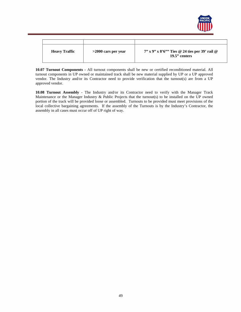
49
Heavy Traffic
>2000 cars per year
7” x 9” x 8’6”” Ties @ 24 ties per 39’ rail @
19.5” centers
10.07 Turnout Components - All turnout components shall be new or certified reconditioned material. All turnout components in UP owned or maintained track shall be new material supplied by UP or a UP approved vendor. The Industry and/or its Contractor need to provide verification that the turnout(s) are from a UP approved vendor.
10.08 Turnout Assembly - The Industry and/or its Contractor need to verify with the Manager Track Maintenance or the Manager Industry & Public Projects that the turnout(s) to be installed on the UP owned portion of the track will be provided loose or assembled. Turnouts to be provided must meet provisions of the local collective bargaining agreements. If the assembly of the Turnouts is by the Industry’s Contractor, the assembly in all cases must occur off of UP right of way.

50
11.00 - BALLAST REQUIREMENTS Under light traffic, crushed rock ballast or equivalent material, per AREMA Standard 5 gradation must be utilized. Under heavy traffic, crushed rock ballast, main line quality, AREMA Standard 4A gradation must be utilized. Refer to Union Pacific Railroad (UP) Standard Drawing No. 0010. The allowable wear based on the Los Angeles Abrasion Test, not greater than 35%, per ASTM C-535. Minimum depth is 15" between top of subballast and top of timber, composite or concrete ties. The minimum depth for steel ties is 8” from top of subballast to top of tie. The full ballast section extends 9" beyond ends of tie for jointed rail and 12" for welded rail and thence to subgrade on not less than 3:1 slope. Ballast shall be quarried rock, crushed to proper gradation, with fully fractured faces. Industry’s Contractor shall provide certification that the ballast meet UP’s Specifications.

51
12.00 TRACK CONSTRUCTION SPECIFICATIONS
12.01 - Experienced personnel skilled in railroad track construction shall supervise track laying and surfacing. 12.02 - Ties shall be uniformly spaced center to center of tie. Ties shall be laid at right angles to the rail and at least one will be located at the joint location as required in the FRA track standards for the class of track it is intended for. 12.03 - When handling or spacing ties care shall be taken not to damage them with picks or hammers. Tie tongs shall be used for this purpose. 12.04 - The pulling of spikes, once driven, shall be avoided insofar as possible. When spikes are pulled, the holes shall be immediately plugged with creosoted tie plugs of the proper size to completely fill the hole, or an approved form of plugging compound must be used. 12.05 - The bottom of the rail, the tie plate and the wearing surface of the tie shall be cleaned before the rail is laid. 12.06 - Tie plates shall be applied at the time the rail is laid to avoid unnecessary spiking. Plate shoulder shall bear against the outside base of the rail. 12.07 - Rails shall be unloaded, stored or distributed along the roadbed in such a manner as to prevent damage. 12.08 - For jointed track rails should be laid with a 12-foot staggered joint arrangement. 12.09 - If a determination is made to stagger rail, then rails of miscellaneous lengths less than 39 feet shall be used at suitable intervals for maintaining the proper stagger of joints on curves. 12.10 - Rails less than 15 feet long shall not be used except for temporary closures. 12.11 - Expansion shims of hardwood or fiber shall be used to control expansion. The following table prescribes the correct thickness for the expansion shim for various ambient temperatures:
RAIL TEMPERATURE
33 FT. RAIL OPENING
39 FT. RAIL OPENING
78 FT. RAIL OPENING
Below 25° F. 1/4" 1/4" 1/2"
25° to 50° F. 1/8" 3/8" every other joint
3/8"
51° to 75° F. 1/8" every other joint
1/8" 1/4"
76° to 100° F. 1/8" every third joint
1/8" every other joint
1/8"
Above 100° F. 1/8" every other joint
52
12.12 - Rails shall be laid to ensure good alignment, and the rail ends must be brought squarely together against expansion shims and shall be bolted before spiking. 12.13 - Rails shall be cut square and clean by means of rail saws. Holes for complete bolting of cut rails shall be drilled according to Union Pacific Railroad’s (UP) Specifications. Under no circum-stances shall new holes be drilled between two holes already drilled. Cutting rails or drilling holes in cut rails by means of acetylene or electric torch will not be permitted. 12.14 - The appropriate number of bolts shall be applied according to the rail joint used. The nuts of all bolts shall alternate uniformly inside and outside of each joint. Each bolt shall be equipped with a spring washer of size required to fit the diameter of the bolts used. 12.15 - The right-hand rail going away from the switch points or the outside rail on curves shall first be spiked in position in its proper relation to the lined end of ties. The opposite rail shall then be spiked to true gage (4'-8 1/2”). Curved track shall be gauged as follows:
a) Lay track to standard gauge on tangents and curves of less than 6 degrees. b) Lay track to a gauge of 56-3/4” on curves of 6 degrees or greater.
12.16 - On tangent track and on curves up to 4 degrees, two spikes (one inside and one outside the base of rail) shall be used to fasten each rail to each tie. On curves at least 4 degrees and less than 8 degrees, two spikes inside and two spikes outside, shall be used on each rail. On curves of 8 degrees or more, use three spikes inside and two spikes outside shall be used on each rail (See UP Standard Drawing No. 0453). 12.17 - Spikes shall be staggered so that the outside spikes shall be on the same side of the tie and the inside spikes on the opposite side (See UP Standard Drawing No. 0453). 12.18 - Rail shall not be struck with maul or heavy tool when spiking, gauging or lining. 12.19 - Spikes shall be started vertically and square and be driven straight with full bearing against the base of the rail. Straightening with maul or spikes started crooked will not be permitted. Spikes started crooked shall be pulled, the holes plugged and spikes redriven. Immediately after completion of track surfacing, spikes shall be settled in place with the underside of the head of the spike contacting the top of base with a minimum of pressure (See UP Standard Drawing No. 0453). 12.20 - Rail anchors control longitudinal rail movement on ties from temperature variations, traffic, grade, and train braking. Anchors are not required on ties with elastic fastening systems unless additional restraint is necessary to control undesired rail movement. Anchors should be new or reformed. On all tracks, apply rail anchors out-of-face along each rail, directly across from each other on the same tie. Use Standard Box Pattern (every other tie) or Solid Box Pattern (See UP Standard Drawing No. 0460). 12.21 - When the track has been raised to within 4 inches of final grade and properly compacted, the final lift shall be made by jacking the track up to the exact elevation provided by the grade stakes. The ballast shall then be tamped under the ties. The space extending from 15 inches inside either rail to the ends of the ties shall be thoroughly tamped. The tie centers shall be left untamped. Unless

53
otherwise authorized, this final lift shall be tamped with tamping bars, tamping picks or by approved tamping machines. In making the finishing lift, the spot board and level board shall be used with care and the track brought to a true surface and required elevation. 12.22 - After track has been brought to true surface, elevation and grade, it shall be given a final lining and placed in true alignment. 12.23 - Turnouts shall be constructed of all new or certified reconditioned rail and other track material. Unless otherwise approved by the UP’s AVP Design/Construction, all turnouts must be fabricated to UP standards. Turnouts in UP owned or maintained track will be constructed with all new rail and other track material supplied by a UP approved vendor. 12.24 - Road crossings on industry-owned trackage may be constructed with plank and asphalt or entirely with asphalt. Maintain the flangeway opening along the gage side of the running rail at no less than 3 inches. All crossings on UP owned trackage will be constructed with UP precast concrete crossing material, per UP Standard Drawing No. 0304, and 200100 through 200903. Curved Concrete Panels, per UP Standard Drawing No. 200902, must be utilized as conditions warrant. 12.25 - Timber crossing materials shall conform to UP Standard Drawing No. 0301 and shall be square-edged and of sound creosoted planks of fir or hemlock, or equal, with the height of plank equal the distance from top of tie to top of rail. The planks are to be fastened with countersunk 3/4" x 12" galvanized Lewis washer head drive spikes, in predrilled holes. 12.26 - Each crossing location will be evaluated individually by the UP (and Road Authority if applicable) to determine minimum crossing surface material requirements. Crossings may require the use of precast concrete materials. Determination of and type of warning devices on public roadways will be made by a joint recommendation of UP, Road Authority, and/or Government Regulatory Body. 12.27 - Earthen bumpers shall be used whenever possible. If Industry chooses to use other than an earthen bumper, they must submit to the UP the proposed device for review and approval. If bumping posts are used, they shall be Hayes Type WD with Shock Free Head, or equal. (See UP Standard Drawing No. 0030).

54
13.00 - DERAILS
13.01 - Derails must be clearly visible. A derail is required for all new construction or modifications of any existing trackage, and it shall be appropriately sized for the designated rail section, complete with proper length connecting rod and operating stand with target. The type of derail required, its placement, and type of switch stand to be used shall be determined by the Union Pacific’s AVP Engineering – Design/Construction or his authorized representative, and will be dependent on track gradient, independent movement of cars by the customer, and anticipated track use, refer to Union Pacific Railroad (UP) Standard Drawing No. 2000, 2005, 2006, 2007, 2020, and 2050. 13.02 - Derails in signaled territory are to be placed at a point sufficiently ahead of insulated joints so equipment is derailed before fouling track circuit. Derails may require signal insulation material as required by UP. If insulation material is required, it will be installed by industry at locations designated by the UP. Walkways conforming to UP Exhibit ‘E’ Drawing must be installed around all derail switch stands. 13.03 - Consideration should be given for placement of derail to avoid conflicts with adjacent tracks, railroad signal installations, communication lines, power lines, pipelines (overhead or underground), roadways, ditches, waterways, storage tanks, buildings, or other structures. 13.04 - Power Operated Derails may be required if Power Operated Turnouts (POTO) are used. NOTE: Special ties on Derail components are required if it is Power Operated.

55
14.00 - WALKWAY REQUIREMENTS
14.01 Safety - Walkways shall be constructed and maintained to provide a reasonable regular surface and shall be maintained in a safe condition clear of vegetation, debris, standing water, and other obstruction, which constitute a hazard. 14.02 Grades and Slopes - Walkways shall not have a grade and slope in excess of approximately 1 inch of elevation per each 8 inches of horizontal length in any direction. Excess slope is permissible where the proximity of adjacent tracks so long as the slope between tracks is constant. 14.03 Construction - For walkway standards refer to Union Pacific Railroad (UP) Exhibit ‘E’ Drawing. Walkways shall be constructed to a minimum width of 8’ 6”, as measured from the centerline of track. Walkways shall be constructed and maintained in such a manner that the elevation of its surface is at least level with the top of ties, but not higher than the top of rail. Walkways are to be constructed per AREMA Standard 57 ballast unless prior approval by UP’s Chief Engineer is granted for alternate size material. 14.04 Requirements - Walkways shall be located along both sides of the track for a minimum distance of 125 feet on each side of every switch stand or other trackside switch-throwing mechanism. Walkways are required around all derail switch stands, in accordance with UP Exhibit ‘E’ Drawing. 14.05 Minimum Distances - Walkways shall be continuous and maintained from the switch stand through the switch frog and along the diverging track. An additional 3 feet of walkway width shall extend for a minimum distance of 4 feet in each direction from the switch stand or other trackside switch-throwing mechanism on the side of the track where said mechanism is located. This additional 3 feet of width shall be gradually tapered back to the 8’ 6” minimum width, as measured from the centerline of track, a distance of not less than 20 feet. 14.06 Guideline - These specifications are provided only as a guideline for design and should not be taken as authority to construct walkways. All walkway construction must conform to the UP specifications or the federal, state or local specifications whichever is the most protective from the standpoint of public safety. All walkway construction shall comply with current and applicable federal, state and local laws. Industry shall be responsible for the proper construction of all walkways. In some areas, the Industry will be required to stockpile sufficient walkway ballast at a location designated by UP’s authorized representative, for installation by UP forces.

56
15.00 - BRIDGE FOOT WALK AND HANDRAIL Any bridge located within 500 feet of a proposed or existing point of switch shall have a footwalk and handrail on both sides of the structure. If the Structure is owned or maintained by the Union Pacific Railroad (UP), the design and installation of the walkway and handrail system shall be completed by the UP at Industry’s Expense. If the structure is owned or maintained by the Industry, the Industry will design and install the walkway and handrail system. The design of the walkway and handrail system must be approved by UP prior to construction. Detailed Construction Plans for walkway and handrail system must be stamped and sealed by a Registered Professional Engineer. Prior to designing the walkway and handrail system, contact the Manager of Industry and Public Projects for guidance.

57
16.0 - FIELD WELDING Union Pacific Railroad (UP) approved welds must be installed. The welds currently approved are Railtech Boutet one shot kits and Orgo-Thermit single use kits. The Industry and the individual installing the welds must be qualified by the manufacturer of the kits being used and have documentation to support such qualification. All welds must conform at a minimum, to meet the latest edition of the American Railway Engineering and Maintenance of Way Association (AREMA) Manual. The link to the AREMA site is www.arema.org. It is UP’s policy that Field Welds made on UP owned or maintained track be inspected by the Director of Track Maintenance or his designated representative.