2012 systems engineering written examination€¦ · · 2012-12-11at the end of the examination...
TRANSCRIPT

Figures
Words
STUDENT NUMBER Letter
SYSTEMS ENGINEERINGWritten examination
Monday 19 November 2012 Reading time: 9.00 am to 9.15 am (15 minutes) Writing time: 9.15 am to 10.45 am (1 hour 30 minutes)
QUESTION AND ANSWER BOOK
Structure of bookSection Number of
questionsNumber of questions
to be answeredNumber of
marks
A 20 20 20B 24 24 65
Total 85
• Students are permitted to bring into the examination room: pens, pencils, highlighters, erasers, sharpeners, rulers and one scientifi c calculator.
• Students are NOT permitted to bring into the examination room: blank sheets of paper and/or white out liquid/tape.
Materials supplied• Question and answer book of 21 pages including formulas on page 21.• Answer sheet for multiple-choice questions.
Instructions• Write your student number in the space provided above on this page.• Check that your name and student number as printed on your answer sheet for multiple-choice
questions are correct, and sign your name in the space provided to verify this.• All calculations must show appropriate formulas and working.
• All written responses must be in English.
At the end of the examination• Place the answer sheet for multiple-choice questions inside the front cover of this book.
Students are NOT permitted to bring mobile phones and/or any other unauthorised electronic devices into the examination room.
© VICTORIAN CURRICULUM AND ASSESSMENT AUTHORITY 2012
SUPERVISOR TO ATTACH PROCESSING LABEL HEREVictorian Certifi cate of Education2012

2012 SYSENG EXAM 2
SECTION A – continued
Question 1
When the camshaft shown above is rotated one complete turn, the mechanismA. lifts and falls once.B. lifts and falls four times.C. converts rotary motion into reciprocating motion.D. works only in an anticlockwise rotation of the cam.
Question 2The thread pitch of a bolt is 1 mm. The bolt is tightened 180° after fi rst contact with the parts to be fastened. How much stretch has been applied to the bolt shank?A. no stretchB. 0.25 mmC. 0.5 mmD. 1 mm
Question 3A mains-operated piece of electrical equipment in a school has been tagged as faulty.Who is allowed to remove the tag and return the mains-operated piece of electrical equipment to service?A. a cleanerB. a teacherC. an approved studentD. a licensed electrician
SECTION A – Multiple-choice questions
Instructions for Section AAnswer all questions in pencil on the answer sheet provided for multiple-choice questions.Choose the response that is correct for the question.A correct answer scores 1, an incorrect answer scores 0.Marks will not be deducted for incorrect answers.No marks will be given if more than one answer is completed for any question.A formula sheet is provided on page 21.Unless indicated diagrams are not to scale.
3 2012 SYSENG EXAM
SECTION A – continuedTURN OVER
Question 4A pedestal drill is being used in a workshop. Sparks and smoke are emitted from the pedestal drill’s switchbox.What immediate action would you take?A. Isolate the pedestal drill.B. Use another pedestal drill.C. Hose the pedestal drill with water.D. Use personal protection equipment.
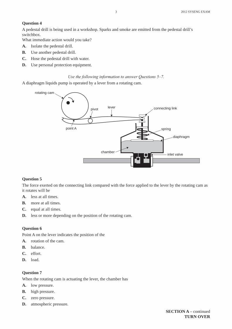
Use the following information to answer Questions 5–7.A diaphragm liquids pump is operated by a lever from a rotating cam.
point A
rotating cam
leverpivot
spring
diaphragm
connecting link
chamberinlet valve
Question 5The force exerted on the connecting link compared with the force applied to the lever by the rotating cam as it rotates will beA. less at all times.B. more at all times.C. equal at all times.D. less or more depending on the position of the rotating cam.
Question 6Point A on the lever indicates the position of theA. rotation of the cam.B. balance.C. effort.D. load.
Question 7When the rotating cam is actuating the lever, the chamber hasA. low pressure.B. high pressure.C. zero pressure.D. atmospheric pressure.

2012 SYSENG EXAM 4
SECTION A – continued
Question 8A bolt is to be tightened with a spanner to a torque of 100 Nm.If the spanner is 40 cm long, then the force applied to the end of the spanner isA. 2.5 NB. 40.0 NC. 250.0 ND. 400.0 N
Question 9
driven gear
24 teeth
8 teeth
driver gear
16 teeth
8 teeth
The gear ratio of the compound gears shown above isA. 5:1B. 6:1C. 1:6D. 8:40
Question 10
pulley A pulley B pulley C
If pulley A rotates clockwise, pulley C will rotateA. clockwise and faster.B. clockwise and slower.C. anticlockwise and faster.D. anticlockwise and slower.
Question 11When a nut on a bolt is tightened, what type of force is applied to the shank on the bolt?A. linearB. torsionC. tensionD. compression

5 2012 SYSENG EXAM
SECTION A – continuedTURN OVER
Question 12
V
12 V load
wire
The voltmeter shown above has a reading of 1 V from the battery to the load.One way of reducing the reading of 1 V when the circuit is operating is toA. increase the diameter of the wire.B. decrease the diameter of the wire.C. put a resistor in parallel to the load.D. put a capacitor in series in the circuit.
Question 13The electric current in a printed circuit board’s copper track is caused by the fl ow ofA. ions.B. protons.C. neutrons.D. electrons.
Question 14A 12 V solar panel is used to charge a 12 V battery. The battery provides power for an electric pump that uses 4 A for 4 hours a day. A solar panel is used to charge the battery and it provides 2 A for 6 hours a day.In the long runA. the battery will go fl at.B. the battery will stay charged.C. the electric pump will not work in the dark.D. the electric pump will work for only 2 hours each day.
Question 15
20 R 40 R
30 R
The total resistance of the circuit shown above isA. 20 RB. 30 RC. 40 RD. 90 R

2012 SYSENG EXAM 6
SECTION A – continued
Question 16
V
VV
V
position A
position B position C
position D
A voltmeter is used to measure the voltage of the battery shown above.In which position should the voltmeter be placed?A. position AB. position BC. position CD. position D
Question 17Which of the following does not detect light?A. a phototransistorB. an infrared receiverC. a light-emitting diodeD. a light-dependent resistor
Question 18
12 R
8 R
12 V
The total current in the circuit shown above isA. 0.6 AB. 1.0 AC. 1.5 AD. 2.5 A

7 2012 SYSENG EXAM
END OF SECTION ATURN OVER
Question 19
A
BQ
Which of the following truth tables represents the circuit shown above?
A. A B Q B. A B Q C. A B Q D. A B Q
0 0 0 0 0 1 0 0 0 0 0 0
0 1 0 0 1 0 0 1 1 0 1 1
1 0 0 1 0 0 1 0 1 1 0 1
1 1 1 1 1 0 1 1 0 1 1 1
Question 20Which of the following is an input device for an electronic system?A. a buzzerB. a relay switchC. a seven-segment displayD. a light-dependent resistor

2012 SYSENG EXAM 8
SECTION B – continued
Before children had motorised cars to drive around, they had pedal cars. To operate a pedal car, the child pushes the pedals back and forth. These pedals then cause the axle to turn.
pivots for pedalscranks
pedals rear axledrive rods
Figure 1
Question 1State the type of motion of
a. the pedals
1 mark
b. the cranks.
1 mark
SECTION B – Short answer questions
Instructions for Section BAnswer all questions in the spaces provided.A formula sheet is provided on page 21.Unless indicated the diagrams are not to scale.

9 2012 SYSENG EXAM
SECTION B – continuedTURN OVER
pedals
15 cm
5 cm
20 cmdrive rods
Figure 2
Question 2If the maximum force applied to the base of the pedals is 120 N, what is the maximum effective force on the drive rods? Show working.
2 marks
Question 3What class of lever is the pedal in Figure 2?
1 mark
Once the pedal car is moving, a child can keep pushing each pedal at a rate of 2 pushes per second.
Question 4a. What is the revolution per minute (rpm) of the rear wheels?
1 mark
b. If each wheel has a diameter of 25 cm, how fast will the pedal car travel in metres per second? Show working.
2 marks
c. A speedometer on the pedal car shows a reading of 4 m/s. Describe a test to determine the accuracy of the speedometer using a measuring tape and stopwatch.
State the expected measurements.
2 marks

2012 SYSENG EXAM 10
SECTION B – continued
pivot for pedals
pedals drive rods
cranks
rear axle
Figure 3
Question 5The cranks of the pedal car are shortened, as shown above.State the effect of this on the operation of the pedal car when the pedals are pushed at a rate of 2 pushes per second.
1 mark

11 2012 SYSENG EXAM
SECTION B – continuedTURN OVER
Figure 4 shows an incomplete steering mechanism for the pedal car.
wheels
steering wheel
Figure 4
Question 6a. On the diagram above, design a safe steering mechanism that will allow the pedal car to be steered.
Label any components you use.3 marks
b. Describe how your steering mechanism works.
2 marks
Question 7a. Identify two processes that you would use in the construction of the steering mechanism that you
designed in Question 6.
1.
2.2 marks
b. State a different safety precaution for each of the processes that you have selected.
1.
2.2 marks

2012 SYSENG EXAM 12
SECTION B – continued
The builder of the pedal car wants to replace the pedal system with a constant-speed electric motor and drive system. A metal disc with a radius of 50 mm and a moveable rubber roller are used for the drive system, as shown in Figures 5a and 5b.
DC electricmotormetal
disc
moveablerubber roller
rear axle rear wheel
50 mm
100 mm
movement of rubber roller
moveablerubber roller
DC electricmotor
metal disc
Figure 5a Figure 5b
Question 8a. The metal disc rotates at 1000 rpm. Calculate the rpm of the rubber roller, as shown in Figure 5b. Show working.
2 marks
b. What happens to the rpm of the rubber roller if it is moved to the right of its position in Figure 5b?
1 mark
c. A child decides to oil the drive system. What effect will this have on the operation of the car?
1 mark
d. How could the builder modify this simple drive system to achieve reverse drive? Suggest both a mechanical and an electrical method.
mechanical
electrical
2 marks

13 2012 SYSENG EXAM
SECTION B – continuedTURN OVER
A hydraulic disc braking system is to be used on the car. The diameter of the disc brake cylinder is 60 mm and the diameter of the master cylinder is 20 mm. The braking system is shown in Figure 6.
master cylinder
brake pedaldisc brakecylinder
axle
disc
brake pads
Figure 6
Question 9a. If a force of 120 N is applied to the brake pedal, calculate the pressure in the system. Include any
working and the fi nal units.
2 marks
b. Calculate the force applied to each of the brake pads. Give your answer in newtons (N).
2 marks

2012 SYSENG EXAM 14
SECTION B – continued
The builder of the car wants to explore the possibility of powering the car with a new technology. He does not want to use fossil fuels. At this stage, the builder does not want to use solar energy.
Question 10a. Name two renewable sources of energy (other than solar energy).
1.
2.2 marks
b. Explain how one of the renewable sources of energy that you named in part a. can be used to power the car.
1 mark
c. Give one reason why your chosen energy source has an environmental advantage when compared to fossil fuels.
1 mark

15 2012 SYSENG EXAM
SECTION B – continuedTURN OVER
solar panel
Figure 7
Finally, the builder decides to power the car with an electric motor and a battery that is charged by solar panels. He decides to use a 2 m2 panel, which generates a peak output of 120 W.
Question 11If the solar cells are 20% effi cient, calculate the minimum amount of solar energy that needs to fall on the panels to generate 120 W. Show working.
2 marks
The process of charging the battery is 90% effi cient. The electric motor used is 80% effi cient.
Question 12Calculate the combined effi ciency of the battery and the electric motor.
1 mark
2012 SYSENG EXAM 16
SECTION B – continued
Question 13The electric motor is operated. It is noticed that, after running for a while, the motor gets hot.Identify two causes of the motor heating up.
1.
2.2 marks
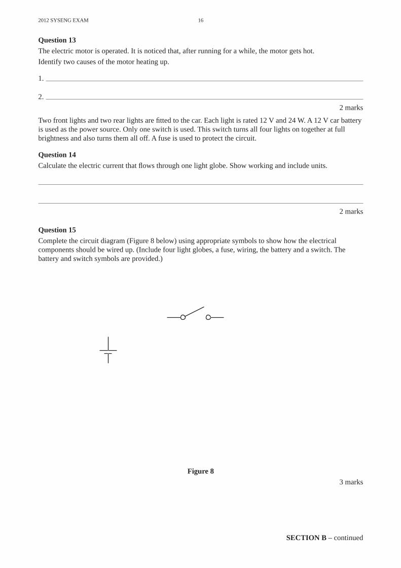
Two front lights and two rear lights are fi tted to the car. Each light is rated 12 V and 24 W. A 12 V car battery is used as the power source. Only one switch is used. This switch turns all four lights on together at full brightness and also turns them all off. A fuse is used to protect the circuit.
Question 14Calculate the electric current that fl ows through one light globe. Show working and include units.
2 marks
Question 15Complete the circuit diagram (Figure 8 below) using appropriate symbols to show how the electrical components should be wired up. (Include four light globes, a fuse, wiring, the battery and a switch. The battery and switch symbols are provided.)
Figure 83 marks

17 2012 SYSENG EXAM
SECTION B – continuedTURN OVER
Question 16The car battery needs recharging after use.State one safety precaution when recharging a car battery.
1 mark
In the circuit (Figure 8) a 1A-rated switch was used and was found to overheat. A possible solution is to fi t an SPDT 10A relay and a new 1A switch.
Question 17a. What do the letters SPDT stand for?
1 mark
b. Complete the circuit diagram (Figure 9 below) to show how the relay can be used to switch the lights on or off, given that the switch controls the relay. (Assume that the light globes and fuse are in the box, as shown.)
light globesand fuse
Figure 9
3 marks

2012 SYSENG EXAM 18
SECTION B – continued
Flashing brake lights are fi tted to the car using the electronic circuit shown in Figure 10 below.
12 V
C13.3 μF
C21 F
+
+
0 V
R210 K
1234567
14131211
1234
8765
1098
ICI4024
R110 K
R31M
Q1 BC337
IC27555
C30.1 F Q2
BD139
R4 2K
7A
B
Figure 10
Question 18a. Resistor R4 is a four-colour band resistor and has a value of 2K7 with a tolerance of 5%. List, in order, the four colours of resistor R4.
1 mark
b. Capacitor C1 has a value of 3.3 μF. What do the letters μF stand for?
1 mark
c. Name component Q1 and name the leg connected to the 10 K resistor.
component Q1
name of leg2 marks
The fl ash rate of the brake light can be changed by increasing the capacitance between points A and B in the circuit.
Question 19State how this can be done without removing capacitor C3.
1 mark

19 2012 SYSENG EXAM
SECTION B – continuedTURN OVER
Question 20Resistor R4 on the printed circuit board is found to be faulty and needs to be replaced.List, in order, the steps needed to fully complete this task. Include the tools and safety equipment required.
3 marks
An oscilloscope was placed across the output LEDs. Figure 11 shows the output that was displayed on the screen.
time – milliseconds (ms)
volts 0 V
Figure 11
Question 21Given that the vertical setting is 5 V per division and the horizontal setting is 50 ms per division, calculatea. the maximum voltage output
1 mark
b. the frequency of the output correct to two decimal places.
1 mark

2012 SYSENG EXAM 20
END OF SECTION B
Question 22Name two mechanical and two electrical subsystems within the child’s motorised car.mechanical
1.
2.
electrical
1.
2.2 marks
Question 23Select one of the subsystems named in Question 22. Give the input and output of this subsystem.
selected subsystem
process
input output
2 marks
Question 24Modern motor cars have many open- and closed-loop systems.a. Name a closed-loop system in a modern motor car.
1 mark
b. Explain why your answer to part a. is a closed-loop system.
1 mark

21 2012 SYSENG EXAM
END OF QUESTION AND ANSWER BOOK
Gear ratio fi nal = gear ratio 1 × gear ratio 2
Efficiency = output energyinput energy
100%
Voltage = current × resistance
Resistors in parallel: Rt = R RR R
1 2
1 2
Colour codesColour Valueblack 0brown 1red 2orange 3yellow 4green 5blue 6violet 7grey 8white 9gold 5%silver 10%
Resistors in series: Rt = R1 + R2
Power = voltage × current
Area of circle = r2 ( = 3.14)
Circumference of circle = 2 r
Force = pressure × area
gear A rpmgear B rpm
number of teeth gear Bnumber of teeth gear A
pulley A rpmpulley B rpm
radius of pulley Bradius of pulle
=yy A
Speed = distancetime
Gear ratio = number of teeth on driven gearnumber of teeth on driver gear
Mechanical advantage loadeffort
Torque = force × distance
Frequency = 1period
EfficiencyTotal = Efficiency1 × Efficiency2
Formula sheet