1988 - willcox corvette, inc.repairs.willcoxcorvette.com/wp-content/uploads/... · electrical...
TRANSCRIPT

1988ELECTRICALDIAGNOSIS
MANUALSUPPLEMENT
TO5T..364..88 EDM CORVETTE
ELECTRICAL DIAGNOSIS SERVICE MANUAL
CHEVROLET
5T-364-885
(
ELECTRICAL DIAGNOSISMANUAL SUPPLEMENT
FOREWORDCAUTION
To reduce the chance of personal injury and/or property damage the following instructions must be carefully observed:
Proper service and repair are important to the safety of theservice technician and the safe. reliable operation of all motor vehicles. If part replacement is necessary. the part mustbe replaced with one of the same part number or with anequivalent part. Do not use a replacement part of lesserquality.
The service procedures recommended and described in thisservice manual are effective methods of performing serviceand repair. Some of these procedures require the use of toolsspecially designed for the purpose.
Accordingly. anyone who intends to use a replacement part.service procedure or tool. which is not recommended by thevehicle manufacturer. must first determine that neither hissafety nor the safe operation of the vehicle will be jeopardized by the replacement part. service procedure or toolselected.
It is important to note that this manual contains various"Cautions" and "Notices" that must be carefully observedin order to reduce the risk of personal injury during serviceor repair. or the possibility that improper service or repairmay damage the vehicle or render it unsafe. It is also important to understand that these "Cautions" and "Notices"are not eKhaustive. because it is impossible to warn of allthe possible hazardous consequences that might result fromfailure to follow these instructions.
! :11) I
CHEVROLET
SERVICE
General Motors Corp. 4/89
This manual provides revised, and/or late productioninformation to supplement the 1988 Corvette Electrical Diagnostic Manual (ST -364-88 EDM) printed inSeptember. 1987.
The revised areas are screened for easy reference.Only changed index, schematic and theory of operation pages are included in this supplement. All thepages in this supplement are update or change pagesto the early production manual. The manual's introductory cells 2 through 5 also apply to this supplement
An understanding of the material contained hereinand in monthly issues of Dealer Technical and Management Bulletins. issued when necessary, will assistservice personnel in properly maintaining the qualityto which Chevrolet cars are built.
All information. illustrations and specifications contained in this Manual are based on the latesi productInformation available at the time of publication approval. The right is reserved to make changes at an'{time without notice
NOTICE: The 1988 Chevrolet contains many partsdimensioned in the metric system. It isimportant to note that. during any maintenanceprocedure. replacement fasteners must have thesame measurements and strength as those removed whether metric or customary. (Numberson the heads of metric bolts and on surfaces ofmetric nuts indicate their strength. Customarybolts use radial Hnes for this purpose, whilemost customary nuts do not have strengthmarkings.) Mismatched or incorrect fastenerscan result in car damage or malfunction, or possibly personal injury. Therefore, fasteners removed from the car should be saved for re-usein the same locations whenever possible. Wherethe fasteners are not satisfactory for re-use. careshould be taken to select a replacement thatmatches the original.

Z-l:Dooc('")-loZ
D
\
~\(,,
B_---J..... - .. I ... ~·
: I,,,,
~\ (,\E1- - - - -' - - --, 'I I
lDirI ,
I
B
Update Change SummaryThe Update Change Summary describes the
revisions, the category of revision, the cell andpage number, and the zone where the revisioncan be located on the schematic. The schematicis seperated into six zones to easily and consistently locate information within Section 8A.Figure 1 below shows the zone locations. It isrecommended that you transfer the minorchange information in the Update Change Summary to your 1988 Chassis Service Manuals.
Index Page
The Late Production and Revised pages areindicated in the index by an asterisk.
late Production and Revised Notes
The Late Production and Revised notes areused throughout the Section 8A Supplement toidentify the type of revision. Late Productionrepresents revisions that occurred throughoutthe model year. This indicates cars were built asshown by the Late Production revision, as wellas the schematic in the respective 1988 ServiceManual.
Revised notes represent revisions thatoccurred throughout the model year as well;however, the cars were built only the way therevised schematic represents. Note, a Revisedschematic supersedes the respective page in the1988 Service Manual.
INTRODUCTION
Figure 1 - Zone lOCitions
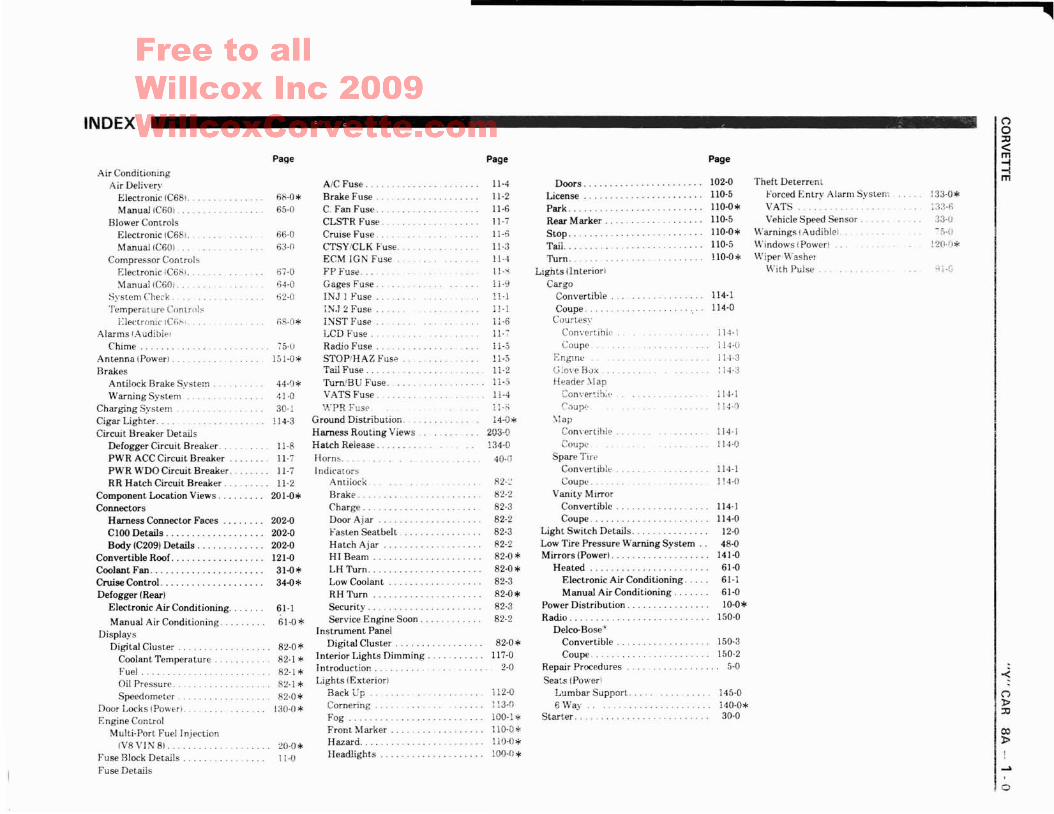
INDEX
Air ConditioningAir Delivery
Electronic IC68! ..Manual IC601. . . .
Blower ComrolsElectronic IC68!.ManuallC60) .
Compressor ControlsElectronic iC6Bi.Manual (C601 .
System CheckTemperature C'1nlrtlb
i,:lec"ronic IC(;I"Alarms (Audiblel
Chime ..Antenna (power! ..Brakes
Antilock Brake SystemWarning System
Charging System .Cigar Lighter. ....Circuit Breaker Details
Defogger Circuit Breaker.PWR ACC Circuit BreakerPWR WDO Circuit Breaker.RR Hatch Circuit Breaker.
Component Location Views .Connectors
Harness Connector Faces .C100 Details . . . . . . . . . . . . . . . . . ..Body (C209) Details .
Convertible Roof. ..........•......Coolant Fan .Cruise Control. .Defogger (Rear)
Electronic Air Conditioning.
Manual Air Conditioning ..Displays
Digital Cluster.Coolant TemperatureFuel.Oil Pressure .Speedometer.
Door Locks (POWH).
Engine ControlMulti-Port Fuel Injection
IV8VIN 8) .Fuse Block DetailsFuse Details
Page
68-0*65-0
66-063-0
67-064-062-0
75·lJ151-0*
44-(H
41·030-1
! 14-3
11-811-7
11-711-2
201-0*
202-0202-0202·0121-031-0*34-0*
61-1
61-0*
82-0*82-1 *82-1*82-1 *82·0*
130-0*
20-0*11-0
AIC Fuse ..Brake Fuse ..C. Fan Fuse.CLSTR Fuse.Cruise Fuse ..CTSY/CLK Fuse.ECM IGN FuseFP Fuse.Gages FU5e.INJ 1 FuseIN,J 2 FuseINST FuseLCD Fuse ..Radio FuseSTOP:HAZ Fuse.Tail Fuse.Turn/BU Fuse.VATS Fuse .."':PR Fuse
Ground Distribution ..Harness Routing Views ..Hatch Release.Horns.Indicators
Antiiock.Brake. . .Charge .Door AjarFasten SeatbeltHatch Ajar .HI Beam ..LH Turn .Low Coolant .RH Turn .Security. . . . .Service Engine Soon .
Instrument PanelDigital Cluster.
Interior Lights Dimming.Introduction.Lights (Exteriorl
Back Up .Cornering.FogFront MarkerHazard.Headlights .
Page
11-411-2
11-611-711-6
11-311-4l1-")
!l-611- 711-511-511-2
jj-4
11-:~
14-0*203-0134-0
40-0
82-~
82-282-382-282-382-282-0*82-0*82-3
82-0*82-382-2
82-0*117-0
2-0
il2-0
100-1*110-0*110-0*100-0*
Doors _ .LicensePark ....Rear Marker.Stop ..Tail...Turn.
LIghts (lnteriorlCargo
Convertible .Coupe. . .
Caurtes'·ConvertibleCoupe ..
EngmcC;!ove BoxHeader _\lapConver~ib:t·
('.:lUPE:
:-lapCom'ertihle .Coupe
Spare TirpConvertibleCoupe.
Vanity MirrorConvertible .Coupe.
Light Switch Details ....Low Tire Pressure Warning System ..Mirrors (Power).
Heated .Electronic Air Conditioning.Manual Air Conditioning.
Power Distribution.Radio. . . .
Delco-Bose"ConvertibleCoupe.
Repair ProceduresSeats (Power\
Lumbar Support.6 Way
Starter ..
Page
102-0110-5110-0*110-5110-0*110·51l0-0*
114-1ll4-0
114·\
114-0
11·1-3
114·:3
114-1
I!H)
114·J114·f)
114-1
I J4-0
114-1114-0
12-048-0
141·061-061-161-010-0*
150-0
150-3150-2
5-0
145-0140-0*30-0
Theft Deterren tForced Entry Alarm SystemVATSVehicle Speed Sensor.
Warnings !Audiblel. .Windows (Power)Wiper Washpr
With Pul5e ..
133-0*133-11.33-0-5·0
120·fl*
4j.!)
("')
oJJ<m-l-lm
...../0

UPDATE CHANGE SUMMARY c:"c»-lm
"J:»2:G)menc:s:s:»:IJ-<
-<ri1>:IJ
o
!I
II
I"o71<iT!~m
Late Production
Late Production
Late ProductionA
A
E,F----
C. E
8A-82-1
8A-S2-G
8A-68-0
8A-61-0
8A-34-~
8A-31-2
8A-44-10--~-_·_------·~-----l~
, 3- _
I i L~ I Change the Overdrive Relay location from RH front of dash, ri~ht of bra-~-l[ 8A-20-10 I 0, F Late Production I master cylinder page 20 1-3-B to in engine compartment. on rear of LHIiishock tower page 201-2-A"
i---- I - ;-----.-------------.--I· ! Change the Auxiliary Coolant Fan Relay location from LH rear corner of i
engine compartment page 201-11-B to front of engine compartment. on .LH rear of radiator should page 201-11 -B *Change the Coolant Fan Relay location from LH front of dash. belowbrake master cylinder page 201-2-A to in engine compartmem. on rear of
LH shock tower page 201-2-A' ,-------------------------, ...--- .----- ------.----.---.--.----..-----,------~--.----,-.----- ..---------- -~"-i
The LT GRf\l (402) wire between connector ClOO. terminal Co and the iInstrument Cluster. temrinal 09. is changed to l T GRN/BLK (402, I
----------,- - ----------------------------1
Revised . In F: Wheel Speed Sensor Test change all 900 ohms to 1100 Orlll!S. tr------ r------------------- -- --------j
The PPL (192) wire between connector C211, terminal C and the RH !HATCH STRUT is changed to BLK/REO 1192; I------------ --------------------------------------- ------------- -----------------1
The BLK (154) wires between connector C10G, terminal F7 and the iB __ Late Production __ Heater and A/C Controi Assembly, terminals 012 and 013 are changed i
i : ! to BLK/WHT (154l, + i c---- ------------------- -------------------- -- ----------
: ~ ; L - P d '_ ; The .35 OK GRN (734) wire between connector C210. termllla! G and, U i ate ro uCtlO" I -- ., I c the In-Car Sensor IS changed to.5 OK GRN (734) i----- _---+ --j- c --------------i
E . Late Production I The.5 LT GRN (11), .5 LT BLU (14) and .5 OK BLU (15) wims at c
! i I terminals C3, C2, and C4 of the Instrument Cluster are ail changed to .8
I i ~e wires. -- -1i A i Late Production I The LT GRN (402) wire at terminal D9 of the Instrument Cluster is !II, II i changed to LT GRN/BLK (402) ~
• For details on how to use this cell, refer to Contents page.
I Page I Zone Rev;';on Categmv Rev,,;on =1Change the Auxiliary Coolant Fan Relay location from LH rear corner ofengine compartment page 201-11 -B to Front of engine compartment, on
I 8A 10 2 C E L P d· I LHrearofradiatorshroudpge201-11-B*
- - , ate ro uctlOn ., Change the Coolant Fan Relay location from LH front of dash, below
Ii . brake master cylinder page 201-2-A to in engine compartment, on rea"~O~f
LH shock tower page 20 1-2-A*
8A 14 2 C 0 L P d· The BLK (150) wires for the LH and RH Fog Lights are removed. Fog ,
- - , ate ro uctlOn L' h d d h h h RH H dl' h 'I ~g ts are no~ groun e t roug t e ea Ig t. , --.---JI 8A-20-5 E R . d I' First Gear SWitch should be shown normally closed, Note IS to read:,II eVlse OPEN IN FIRST GEAR.

UPDATE CHANGE SUMMARY
• For details on how to use this cell. refer to Contents page.,~------------------'-' '---"'----_._--, .L------Page i Zone ! Re_~ision ~ategory --l R~vision ._~__:-_;_------- . , ---J
I AiL Pd' I Tne.5LTBLU(14)wlreoetweenconnectorC100,termmaIG4andthe, ate rouction :. ,
: i • Instrument Cluster IS chanQed to .8 l T BlU (14) ISA-1 10-1 1---------~---------~-,.--. ~----~-------~--~ --.---------------------,
, E 'L· Pd' : The.5iJKBLU'15Iwirebetw.eenconnectorCl00,terminaiG8andtheatp. . ro uctlon . CI·· , 8 DK BlU (15):r:strument uster IS cnanged to . .
8A-114-0 8 Late Production The .35 RED (9561 wire between spiice 5402 and the Diode Module ischange to.5 TED (956)The .35 WHT (156) between spiice 5415 and the Diode Module; and the35 WHT 1156} between splice 8415 and connector C209 are change to5 WHT (156).
I~-i-im
-<("')
l>:JJ
c:"tJol>-im("')
:I:l>2C)mU)
c::s::s:l>:JJ-<

lH REAR lH BACK UPMARKER CORNERING LH BACK UP LH TAl!.. PARKi liCENSE RH TAil PARK!
LIGHT !:.!ill!! h!!lli!. STOP/TURN LIGHTS lIGH!. STOP/TURN LIGHT
,,- .... /-\ ....... ,..---.... ,---, ,.- .... ,----, ,...---.....{ \ ' " I \ I \ I "I I I ' IJ \ J " I I I~J
I ,I •\, _/ '- ...... ........ , I " I
" "'---' ....._--" '---' """'----
3ROUND DISTRIBUTION: G401REAR LIGHTS GROUND LATE PRODUCTiON
tAl
~(")
~::c
(Xl
l>!-,J::.
A
~~UNIT
r--""I II II I
L_J
BLK
1 BLK 1150
RHREARMARKER,.-I '\\ I
./
,. ....I \\ J........
IlH BACK UP
CORNERINGLIGHT
.8 BLK I 150 .5 BLK .,50
RH BACK UP
~.....,I J,_....
.8 BLK .,50
HIGH lEVELSTOP LIGHTr--.,I II II I
LfB
CONVERTIBLEONLY
.5 BlK .150
150.8 BLK150.8 BLK150.5 BLK150.8 BLK150.8 BLK150.8 BLK150.8 BLK150.5 BlK
CONI/ERTIBLE COUPE
I '
-=G401
(")
o::c<m=1m
~
~~,--,I II II I! IL._~
HIGH LEI/ELSTOP LIGHT
r--"'"I II II II II-.__...!
B
't".,8 BLK 1150 1 BLK 1150
IS40J
J BLK 150
.... G401
A C4GJ
Alllrtl'AAlrfENhaUAV ..MilAYC~Mert0~ .·e,m1'9Rr~"'1·t07]I I .•... 1 .,I 'r' .·11-L_d ...........-1
.B BLK 1'50
150
HATCHAJARSWITCH....---,I II II II IL __..l
A'
150
.8 BLK
1 BLK
150
150
1 BLK
CONTROL MODULE
r--------------,I II II II IL. J
34"'---loY--zo
1 BLK
58LK
150 C400 150
C402
ANTENNA ANleN." LBeow RHBoW'-lAY 1UI'll.NA lillA' ... A£~EAst RELEASE MODULATOR MODULEWAiITOIl RELAY ~Toll; S01;£IIIOI» SOLENOID VALI/E RELAY
1"""......, r"'-'11
F"""', r--l r---' r--"j r--l'" • I ,I I I I , I II II 1'11,1 II II iI II t I .1 • I I I I I I
:~~,:l-t-~~t:=-::::J[:-~-' ~ -~::r-f_:~~"----. . .....
-~ 150 I~150
2BLK B 2BlK" ,
C
5 BLK 1150
MODULATOR
~r'--"t I
II
i I
5s:r:0J BlK
A_C448

HEADLIGHTS: FOG LIGHTS
--A --------------1 11GHTliTCIRCUIT I SWITCHI BAE •• EA II~."",_~ I
: "E'D~fi~'AD ':":I" ,._ i I: I PA~. ?AA.
9-j,. iL \1 "
J
LATE PRODUCTION
.oiiIfMii'l'iI..-1------, FUSE
: ~ l!lli, i BLOCK
:'~ :I ~ 10 AMP Il_~ ..J
(")o::D<9m
8DRN .240
Fr-\~---ll1GHT
I .. I SWITCH: "HA[] 'O~, :--
I~· II l~AHI' IL_:"'~ J
EI8 8RN 9
SEE LIGHT0 " SWITCH DETAILS
S21~ CELL 12
2 YEL
2YEL. '0
o 'If a
y """',,;,,10 F DOORS
C CE LL
I ' '"'• HEADLIGHT"'.. \- IDIP~MER-_____ Le SWITCH
I - - -....' !
'"
.8 BRN
)LTGRN.,1 lTAN.12[ZJ
B_. illLIGHT! SWI1CH
C - -
.8 PPL .34
-<o:r>:D
, ......
00:r>I-ooo

~
n»::c
.....
no::c<m~m
00»I-oo
SEE GROUND
DISTRIBUTION
CElL14
·•••••1111.11111.1•••••·••
.BLTGRN 111
'Li LT GRN I li
.8 PPL134
C4tCl00
.B PPL 34
·":r·~'--.::I"CD !.!!. (D!!!iFOG FOG
LIGHT LIGHT
A \J A
BLTGRNlli
1 LT GRN
11
12
~
B4~BQ.Q.
1 TAN
11lLT GRN
11 ~. -----~1~TA~N~----------_----_1 TAN 12
• A-g" 1--',:~:L_~~,I" ._-----1! c~ -~)--~"-----i ~:,"""" '''~:J~1 TA:r~, _ 1 :'. """'''"' , """""'"" r A -------. --------I _ _ : ASSEMBLY I C ." ' RH
1,.--- ' ,~ D' RH lHEADLIGHT
________ J : t ",""U"",' ""'" .,,"'I _ _ I ASSEMBLY
DISTRIBUTION 1~:" '-----·~~I'(:CELL 14T """" '"" ,~-
L _ - i"'" :.:" '"'""·'""""~~:'" ''''i=--
~Qill.
11
.B LT GRN
150
150
.. G201
HEADLIGHTS: FOG LIGHTS
~.---,
1
5 BLK
3 BLK
,'3,-- '-:i-------, INSTRUMENT
I I HI : CLUSTER; A _ _ __, CV BEAM I SOLID STATEI cj INDICATOR: DO NOT MEASURE
: .~ _ I RESISTANCE 1 LT GRNT -0 I: .--... =. I
! ,iNDICATORS IL ~ .J
01

2 PNK 1 76
.:[.I.'~I;III~.
LATE PRODUCTION
POWER WINDOWS
~
f\)oo
..(
C"J»::J:J
I~I
-;;-----' FUSE- I--WOO I~£!!!£!!.!!.. IBREAKER I30 AMPS I________J
1"--II!IIIII.._-
N ~C290
2PNK 176
IiIC"J,0
I~!;1
RHWINOOWSWITCH
DOWN
161HAN
fiB
"Jil-- --- - ---~:~J:::l
I '"1 i l' I RH
i 0.. l. IMNOOWI IMOroR~' ~--L ' !
2 OK at UlWllT11ft 2 JAN. 1&1B II
2 OK BlUlWlfl
SEl8R&UIDDlS11lI8V11OlI
150
_8 BLK~__.....~ ELECTRONIC
II MR CONDITIONING
150
~ G201
J BLK~....ClI.-rAeAlIl.f.
::11"..I (~ : I~NOOW.I V MOTOR
i ~_ t!.-! • I
i
2 PNK 1 2 PNK
J" ~ " J~~~NOOW ' ! l'uLld_SW
_
1T
_
C
_' T "' l!n"'B~lC' IL 2BLK I 2 BLK
150 \ I j 150
• ..2 .BL.K ~. 2 BLK
10K BLU 116~ 2. B.R N 1.65 150 1·!SJ!!!0!!J--.,.60----------~2.LT~BL.U.I •• '6.6LIl WINDOW 2 BlK 150 !til WINDOWMOTGIl CAPACITOR MOTOR CAPAtnOR
!!!!!-EiE3-.~ ~i-E3E3-.ll!!1
2 OK $lUI.•..164 2 (}R~I.•..'.. lI.11 J""- . au"1.."'11. ... llA•...lt.,G -----------il. 3 BLK 150 •. ll---------,j &2811
I 5211 .---.... BtE_
10K8l:t'~ 2_8~~I:~1 C:1'50
0I8fR1IUTlU
10K8t: 164 2IlR:ll-:- SZIJ • ....

REV1SEDPOWER DOOR LOCKS 1(')
1°I~I ,~
I:J111'1
I
195~ 1% ~195
-;----pWRACCV1 FUSE: ., Ci'iiCUiT I BLOCK
! .) iiREAKE A :I '" iD"AMP Il_ .. ..1
J DAN/BlK 160D J OAN/BlK . J DAN/BlK a 2 eRN/BlK
1---------------....))))1-.....0..;------. .a:o(~!It ..... , n 'Pi
C501 60 I~ 60 C601 50 1..·..20AN/BlK 60 - -.
A ~ AlH 000 A SEE FUSE ,....--.---:.:;?!"i--.----,l pc DOOF
UNLO~K LOCK ~ I, lOCK . L!~LOCK, '.OCK---t - BLOCK DETAILS • ., !-'-
N 'vi ~ ! N '~ l~1** *);(1
O}81 EI]2UK C 2BlK C 2BLK----19115-----..~:)~----·194------------1II(j( ...,----...194~-
______~2~l.TiiBl.U_--...L)lo------------.;2.:il.;.T.;;B~LU;;.----__~~..1---_2.l.T.Biiil.u-----
2BlK .150
2GRVII295 2 BlK • 150
2 TAN 294
~. )) Ii2 GRY
.. ,"PiG-';;:S:;MiNG'::;:"'-" ~HEFT".... 4-_ :D~~
CO"TAOl~!.!!
'='
~
Wo
(Xl
:Po
-<(')
l>~
( ~,
5601
1.-8-I' SEE GROUND
::~:r:1:~-- ,,~""~SEE GROUND
.I~--~ DISTRIBUTION
- BLK 150
d BLK _L£CTRONIC
• ... ~IA CONDITIONING;~.:..,. '150!It .~\4
GAY
EACH MOTOR CONTAINSA SELF AESETTINGCIRCUIT BROKER
2..... 295 :.1I l' ?I'. AH OOOA, -
i~ < lOCK, ' MOTOA
fAN
294
B
<E
C6il!
1 GAY
295
''£c':~~ ·1;
Q3UD 51 AT~
~', )'-' q", , ~ (; .... ,', ''If' ~
GRY
GV m
l'rt.rt.l
294TA",j Z94
B
»C501
295
~2%
2Soi
iTA Ii
r I".,f' ?1Vr
S113 •
.,
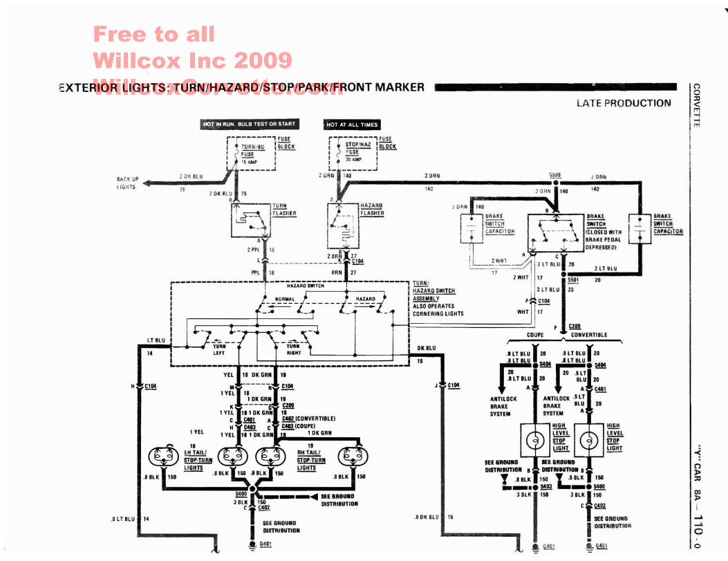
EXTERIOR LIGHTS: TURN/HAZARD/STOP/PARK/FRONT MARKER
o
~(")l>::lJ
ex>l>i~
~
o
IQ
I~I~III
BftAlCESWHcH~TOR
J
148
20RN
LATE PRODUCTION
-HOT IN RUN BULB TEST OR START
, YEl
14
£!.!!
14
,.-r------., FUSE
I ~~ lSLOCK: ), _FI_JS_E :lJ: \5 MoP !
4.---:.~il.X.S.lU__.'I-------75 2DK8l~ 15
§: -- ;~::HER ~'!"'~' r::~' Rli BRAKE. B1tA.. KEL.:::l ... : ._____ 'SWlTCH SWlTCK- 1 -~ : "r I::.::CA::..P::.:AC':;..IT:..:;Oc;.:H (ClOSED WilliI "-, . I 1-AI c:;-- I , , Bl\AI(E I'EOAI
ZPPl 16 8 ' ~ DEPRESSED}
28RNX27 Ii A CJlr-------"--------~~C104 I!~-~- ~ 2lTBW 20
Pf'l 16 BRN 27 '17. HT BlU •
----------- ----------, TURNi 2 WilT, i17 I~ in, HAZAAO SWITCH I -- ,I 2 I HAZARD SWITCH '21T BlU 20
} NORMAL f HAZARD f I~ p.u CI04
.-- L!-::----l~1---- ~1--·1-1 I;~:::::::::~:"" ..·IT'-1-I I _.., I i Hip19j!!I "'~1 - • --. --. I I COUPE CONVERTIBLE
lULU I ~ r-~-- I I" \
I ~~:: I .IlTBlUJZO .8 LTBLulzo
L-__ l;~::~:·:"f;;t:MI- -----;}- f!!! J -- ill!. A Al &401
lYEL 18 I-I OK GRN 1. ANTI lOCK ANTI lOCK .5 IT
K -----G ~ BRAKE BRAKE BlU ZO1 YELl1. 1 OK GRN 1. SYSTEM SYSTEM A
C JO!Il A f!!!.(CONVERTIBLEI
HI C4I3 C ~ICOUPE) !!!!!.!!. i t!!Jil!1 VEL ImK GRN 1 OK GRN ~ ~
STOP STOP
~1. @ 19 i:iGiiT UGHT
lH TAILI ~ RII TAlll -- --
STOp·TURN ~ STOp·TURN SfE 8aOUNO lEE IIROUID
I !1!!!!.!! 8 BlK l1liO 8Bl K 158 !J!!!!! OI8TRlIUTION. DlSTRlIU1IOIl 8· -.8BLK150 .~. .8BlK 158 T .BllK I,so Y .5BlK' 158. ._IIII!!I!I!~. __.• §!!a ~_.S400
~ ---~ SEE SHUND 3 BLK1'503 BLKl'58
3 Bl~ h~02 DISTRIBUTION Cr~T- .8 OK BlU 15 SEE GIWUIIO
SEE GROUND I DISTRIBUTiONI Dl!TRlBUnOtil
~~ .~ i~
H
BAC( UP
i.1&HTS
.8 LTBLU

~
WW
<Xll>!
o
(')o:::c<m-l-lm
-<(')»:::c
REVISED
..-r------, FUSEI ~ CTSY/CLK I BLOCKI (FUSE I
I 1"'i"5'AMP :L ..J
HOT AT ALL TIMES
6r--1---------, TELLTALE
I ), l~I <]) "SECURITY" II INDICATOR II IL_I J
5' .
2DRN 140
-. SUE•..1ill.e---- lIlocit lJrrNu
.5DRN 140
.5 OK GRN I Z64
RADIO
HOT IN ACCY OR RUNo...-r------' FUSEI RADIO I BLOCKI FUSE I
ll~:~-JI~
43
28
..!!.Q.!!!!.
.!!ll£
HORNS
2PNK 1940
.35 YELl 43
r------------I ~ THEFT -., AUXILIARY
I FUSE ItillI ~P I BLOCKI l-~
I IL___ I2 PNK .n-------.1
J
-
.5 BLK
ELECTRONICAIR CONDITIONING
••,5.B.LK,..HORNS •• •
28
.B BLK 1150
3 BLK .150',N
'M "" r"POWERDOOR 1 GRY POWER
LOCKS • DOOR
• 1295 LOCKS
j'" PWR'AcCY-lf..!!g,: CiRcUiT I BLOCK
I BREAKER :
LI~~ J30RN/BLK 60
30RN/BLK 30RN/BLKr 60 Sl08i~
2 DRN/BL:I~:' :i....~)."',,:"Il6:
601
OlTMitiA A
UNLOCK l' LOCK ~ rJ~i:J~iEi~ !!!!~ DOOR DOOR
t-.....1 I LOcK loCK-1 .J. SWITCH SWITCH-=--,;:~..,:r;...,.::....".---'
'~!~ ;~ftt411 ;~ 2M 'tIiRY 196m! liS
1TAN 1 GRY
.1le~"·C'.·..' Felli!294 ':. 95
t SEEGltllU8D ~~-S601POWER OISTRI8llTlO. 2 BLK 150DOORLOCKS Cy C601 .BBLK
~N Z94 2 GRY 295 -B , E 150~------ OOJ_C5_01
HOT AT ALL TIMES
1TAN ,'294,"11 INOT USED),'A ./' G E~L FA N'" KJ. 0
-f~-m~R;'~-f-~d"';-'''M''--------------------'---~-;~7:.;---------:;;;----t---::;;-------~------ ~:~;::;-1;:::;"'.,I INPUT INPUT INTERRUPT OUll'UT INPUT ON INPUT INDICATOR I CONTROLLERI CONTROL CONTROL CONTROL I -=-:':':~~~i I SOLID STATEi, -= -= J t - t - I DO NOT
I WITHP~OOOR !- ~~~~ -= .J ~ ~~~~ I MEASUREL__ 2:~~.!~~ ~ ';. .J RESISTANCE
THEFT DETERRENT SYSTEM
FORCED ENTRY ALARM SYSTEM
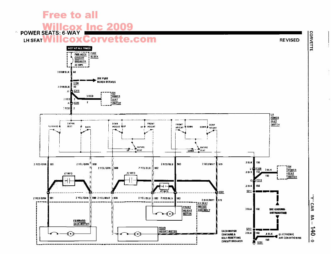
" POWER SEATS: 6-WAYLH SEAT
.-::r.j"DW·,•••,~I:«.'"
REVISED
(")o:::D<m-f-fm
flpwAACCYl FUSE, CIRCUIT' BLOCK1 BREAKER 1--L 30 AMPS ,_ _ ..J
J ORN/BLK II 60
•__-+- SEE FUSE
IS108 BLOCK
J ORN/BLK ~ DETAILS
A~C319 r---3 REO 2 • __3.RiiiEiiO_..l
1 l!!!!I I POWER
A
rC320 2 I :SEAT
j REO 2 l .J~
~-------------------------------------------------------------------
o
GO:t>I~
~o
-<("):t>::7J
~--'RH, ,-iG I'~.. "SEAT
L __JSWITCHC- C319
3 BLKT;;-5211.__-..
I..
3 BLK • 150
C3 BLK
3 BLK .150 SEE 8Ra_DISTRIll1lllItf~
I5213i__-.I
3 BLK 1/50 .8 BLK elECTRONIC
.----~~ AIR CONDITIONING150~ G201
EACH MOTOACONTAINS ASELf·R£SUTlIfGCIRCUIT BR£AKE R
979
979
2 REONlHT
~ ~C~1
2 REO/BLU • 983
~HEIGHT MOTOR
9832 REONlHT
II --------j LH SEAT, i , , FRONT I MiiTiiR
HEIGHT lASSEMBL V
!!!!!!!!
2 VEl/BLU
.41 MfD-i
2 VEl/ORN 1\ 980 i\\ 2 VEL/GRN 1\1980
~~~~.l I: II:
\ \\
2 REDIG RN I 981
2 REO/GRN 1981

30RN/BlK 160
POWER SEATS: 6-WAYRHSEAT
00»I
....
~CO)»:Xl
-~oREViSED
'PWR'A'ccY'l FUSECIRCUIT I BLOCKBREAKER: --3D AMPS I-------'
ro-IIIIIL_
3 REO
e""""" ...... ..",... SEE FUSE
Ill!! IlOCIl OETAllS
30RN/BlK 60
A ...,C319"'" r---, lH3 REO A 3 REO I .-, ) I I~
C320 2 , I~- L __J~
.,
("')o:a<m:::Im
150
~--,
J BlK C 3 BlK I I!J:!......~ I~150 ~150 I :~C.a, £ill L __..J~
3BlK 150
S211e__~
IA
JalK .l.~~....
I@e__..J
3 BlK I/O .8 BlK ElECTRONIC
150 4 AIR CONDITIONING
~ G201
EACH MOTORCOIfTAIfIS ASELF-RESETmlGCIRCUIT IREAKER
979
979
REARHEIGHT
2 REOfoYHT
FRONTHEIGHT
~----------------~~
2 REO/BlU I 983
REARii'EiGHT MOTOR
FRONTHEIGHT
2 YEl/BlU I 982
REARHEIGHT
2 YElIWHT II 978
BACK
2 YEl/GRN II 980
FORWARDBACK MOTOR
~IREFORWARD ~ SEAT
I
983
·----------------~--------~---------------'~---------I IRH~~~IWHT~FRONT I MOTOR
HEIGHT IASSEMBLY
!!!!.!!!!
I • l!!!if!!mill!~
~-------------------------------------------------------------------
2 REO/GRN I 9Bl
2 REO/GRN 19B1

POWER ANTENNA
HOT IN ACCY OR RUN~..LATE PRODUCTION
(')
o"<m-l-lm
o
-<("")
»;:g
CO»,...Jo(J1...Jo
IANTENNACOAX LEAD
r~----, RADIOI II II SOLID i
I SlATE :I II II I'-- --...
ft ANTENNA'1--·---[I MASTn~ j
i ;L..1 ;0 UP
UP '.... 1DlIWN
SWITCH 1UP
I ¥<z i ANTENNAMOTOR
!-!!!!!!
BRAIDEDSTRAP
WHT
GRY
nGI'I~_.~1',_,-----1 I;DUWtrCH: UP I
OK GRN ' ~ I Il---sj i !-.... DDWN...... I! I
CONVERTI8LEONLY
"NTE~NA
,RELA'!~l(1R
A-----------
i
Hie~I!I
idA
I '* ~.. - ."" I gANTENNA~~IUR
151
I1, __,..8 8.t.K•• -_ .5403
100 -
II SU&ROUMDDISTRlIUTIOfI
II1~!!!!!!
iT
DelCO·80SE~
RADIOONLY
18LK
,8 PNK 1143
~!ill
, BLK .151
---------, FUSE, ,--: ; RADIO ~.' CTn/ClK !BLOCK,! ? rUSE :' FuSE i
',II",' " J5iE, ,~" ~ ~_":'I~:~:!' J';:'ffiflE>i' <1... _
t~l~:l ~ Sff FUSf____________ ~_,~~"''''" :.J~~--.... HLOCK OETAILS
, !---r---""! , \...lIlt:;
i Sl'UU I li 1--(S"tAIEI c'rt_~~l ZQP~ 40 SHFUSE
i l..---~-"--"--4 I S'O'. .. BLOCKOETA'LS
,~ .- ~ B~R~ fO ,COUPE:'
-·--.-"'==-.,-""'-,"·-.,----~..","·c-: ", O~N 0 icor,VERTiBLEi"I Ij"- SEEfUSE,1"iK ."" i43 S~,12. U_li__+ BLOCK DETAILSc. ..JA C209 - I-~- 8()R~ 4C ,
8pr,K !'43 , ~
£1 RELAY

( I
Figure A . LH Side Of Engine Compartment
-<C1:t>jJ
N
(jojJ
<m-I-Im
'(Xl
:t>INo....10
I
I I! I
12H241
OXYGENSENSORCONNECTOR
OILPRESSURESENDER
//
,.,~
LATE PRODUCTION
All fP-oN1~ Of CJ'),P-
Figure B· LH Rear Of Engine
OilTEMPERATURESENSOR
IOILPRESSURESWITCH
\
I ~
l!;II,I.
! !! !, ,I I
l
II-
,-
12H2.1
, -----,
COOLANTFAN RELAY
BRAKE FLUIDLEVEL SWITCH
S123
/ JA~~\\
COOLANT FANTEMPERATURESWITCH
-- ;::::.
.'"': ~..'/~~:/.;~~ Iii .~~: .. ~ I1~ !i
'I I'll/, II /~'~~~J
f~~. ~~~af GENERATOR
COMPONENT LOCATION VIEWS
III!!

w
I
II
, IJ !
I
6N44,1
)2 H.·~ '1 ~
Fiyure C ' Below LH Side Of liP
TCC/CR UISE ,._'-,BRAKE SWITCH~ ,/;;:::>-~i)
/;-: ,/. ;'&/-;/
~/~'
,
//' ~_.".,/,/ AI;/ .\// ~ ,
, :~,~,/;X,"" 'M£,~,~>;t. \\,·pMfb / r/\ \ .::::f ,'....... ', '
CRUISECONTROLCLUTCHSWITCH
-~~-.~ -,
/~~/,/'~-I ,,1 • _,,~ ,
d~\ il,j,:._~
4IJf' AV"';,~~ -" -<,)I,/" ~ /<'~,J'
- '" A~"" /fUEL \\;/ -:.YPUI\iiP;lj /ff::/Rr , "V ,j ,y
- '::'-1-'., ~"\ ~••/I \" ,! ~~\,;\~ ~\-)\/
'{g.'!Jqi'c<Ti" 10~lV'
I ~"~.,'
- • "'" ..; 'LH Frnnt rif n"dlFigure 1) ,
12H27 )
Figure A . Rear Of Engine
BACK UPLIGHTSSWITCH
~ FRONT,. OF CAR
COMPONENT LOCATION VIEWS
ELECTRONIC SPARKTIMING (EST)OISTRIBUTOR
I
-<()l>::c
00l>INo-lo
......
12H7.1
1231:10;:;';) i
I'2.~,,~,"-~-l I
j II i1 !
i iI J
I I: ;l !1 •
Il Ii I
I II I ()
o::c<m-I-Im
LATEPBOtlttC'T.ON
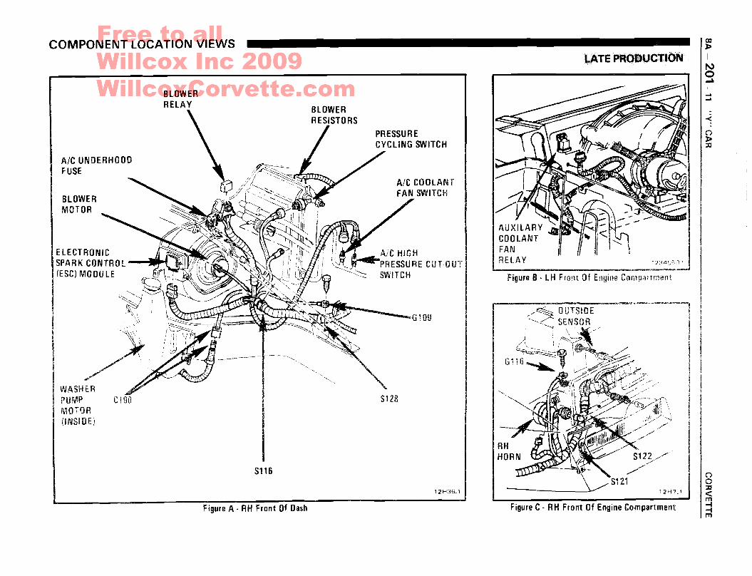
Figure C· RH Front Of Engine Compartment
Figure B· LH Front Of Engine Compaitment
12H36.1
5128
A!e HIGH~PRESSURE CUT-OUT
SWITCH
Figure A. RH Front Of Dash
AIC UNDERHOODFUSE
Sl16
BLOWERMOTOR
-~".'~.\ .
~..,/
WASHERPUMP' -MOTOR L lun
(INSIDE)
BLOWERRelAY
ELECTRONIC
COMPONENT LOCATION VIEWS

CHEVROLET