18- cd29d1- 7 installer’s guide · pdf file4 18-cd29d1-7 installer’s guide...
TRANSCRIPT
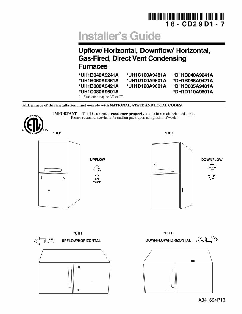
Upflow/ Horizontal, Downflow/ Horizontal,Gas-Fired, Direct Vent CondensingFurnaces
ALL phases of this installation must comply with NATIONAL, STATE AND LOCAL CODES
IMPORTANT — This Document is customer property and is to remain with this unit.Please return to service information pack upon completion of work.
Installer’s Guide
*__First letter may be “A” or “T”
1 8 - CD2 9 D1 - 7
UPFLOW
*UH1
UPFLOW/HORIZONTAL
A341624P13
*UH1
*UH1B040A9241A*UH1B060A9361A*UH1B080A9421A*UH1C080A9601A
*UH1C100A9481A*UH1D100A9601A*UH1D120A9601A
*DH1B040A9241A*DH1B065A9421A*DH1C085A9481A*DH1D110A9601A
*DH1
DOWNFLOW
DOWNFLOW/HORIZONTAL
*DH1
© 2011 Trane All Rights Reserved 18-CD29D1-7
Installer’s GuideSAFETY SECTION
The following safety practices and precautions must befollowed during the installation, servicing, and operationof this furnace.
1. Use only with the type of gas approved for this fur-nace. Refer to the furnace rating plate.
2. Install this furnace only in a location and position asspecified in “Location and Clearances” (page 4), ofthese instructions.
3. Provide adequate combustion and ventilation air tothe furnace space as specified in “Air for Combus-tion and Ventilation” (pages 8-9), of these instruc-tions.
4. Combustion products must be discharged outdoors.Connect this furnace to an approved vent systemonly, as specified in the “Venting” section (startingon page 15), of these instructions.
5. Never test for gas leaks with an open flame. Use acommercially available soap solution made specifi-cally for the detection of leaks to check all connec-tions, as specified in “Gas Piping” (pages 31-32), ofthese instructions.
6. Always install the furnace to operate within thefurnace’s intended temperature-rise range with aduct system which has an external static pressurewithin the allowable range, as specified on the unitrating plate. Airflow with temperature rise for cfmversus static is shown in the Service Facts accompa-nying this furnace.
7. When a furnace is installed so that supply ductscarry air circulated by the furnace to areas outsidethe space containing the furnace, the return airshall also be handled by a duct(s) sealed to the fur-nace casing and terminating outside the space con-taining the furnace.
8. A gas-fired furnace for installation in a residentialgarage must be installed as specified in “Locationand Clearances” section (page 4), of these instruc-tions.
▲ WARNING!CARBON MONOXIDE POISONING HAZARDFailure to follow the steps outlined below for each ap-pliance connected to the venting system being placedinto operation could result in carbon monoxide poi-soning or death.The following steps shall be followed for each appli-ance connected to the venting system being placedinto operation, while all other appliances connected tothe venting system are not in operation:
1. Seal any unused openings in the venting system.2. Inspect the venting system for proper size and
horizontal pitch, as required in the National FuelGas Code, ANSI Z223.1/NFPA 54 or the CAN/CGAB149 Installation Codes and these instructions.Determine that there is no blockage or restriction,leakage, corrosion and other deficiencies whichcould cause an unsafe condition.
3. As far as practical, close all building doors andwindows and all doors between the space in whichthe appliance(s) connected to the venting systemare located and other deficiencies which couldcause an unsafe condition.
4. Close fireplace dampers.5. Turn on clothes dryers and any appliance not con-
nected to the venting system. Turn on any exhaustfans, such as range hoods and bathroom exhausts,so they are operating at maximum speed. Do notoperate a summer exhaust fan.
6. Follow the lighting instructions. Place the appli-ance being inspected into operation. Adjust thethermostat so appliance is operating continuously.
7. If improper venting is observed during any of theabove tests, the venting system must be correctedin accordance with the National Fuel Gas Code,ANSI Z221.1/NFPA 54 and/or CAN/CGA B149.1 In-stallation Codes.
8. After it has been determined that each applianceconnected to the venting system properly ventswhere tested as outlined above, return doors, win-dows, exhaust fans, fireplace dampers and anyother gas-fired burning appliance to their previousconditions of use.
9. The furnace may be used for temporary heating ofbuildings or structures under construction onlywhen the following conditions have been met:a. The furnace venting system must be complete
and installed per manufacturers instructions.b. The furnace is controlled only by a room ther-
mostat (no field jumpers).c. The furnace return air duct must be complete
and sealed to the furnace and clean air filtersare in place.
d. The furnace input rate and temperature risemust be verified to be within nameplate mark-ing.
e. 100% of the furnace combustion air require-ment must come from outside the structure.
Safety signal words are used to designate a degree orlevel of seriousness associated with a particular hazard.The signal words for safety markings are WARNING andCAUTION.
a. WARNING indicates a potentially hazardous situa-tion which, if not avoided, could result in death orserious injury.
b. CAUTION indicates a potentially hazardous situationwhich, if not avoided, may result in minor or moder-ate injury. It is also used to alert against unsafepractices and hazards involving only property dam-age.
18-CD29D1-7 3
Installer’s Guide
INSTALLATION INSTRUCTIONSGeneral Installation Instructions 3Location and Clearances 4Outline Drawings 5Upflow Installation 7Downflow Installation 7Horizontal Installation 7Air For Combustion and Ventilation 8Duct Connections 10Return Air Filters 11General Venting Instructions 15Venting Material 16Venting Tables 17Horizontal Venting 20Venting Through The Wall 20Venting Through The Roof 21Downward Venting 23Venting Through a Masonry Chimney 23Condensate Drain Instructions 26Electrical Connections 29Field Wiring Diagrams 28Gas Piping 31Combustion Input Checks 32
Start Up and Adjustment 35Preliminary Inspections 35Lighting Instructions 35Sequence Of Operation 36Control And Safety Switch Adjustments 36Airflow Adjustment 36
Abnormal Conditions 37IFC Error Flash Code 39
GENERAL INSTALLATION INSTRUCTIONSThe manufacturer assumes no responsibility for equip-ment installed in violation of any code or regulation.It is recommended that Manual J of the Air Condition-ing Contractors Association (ACCA) or A.R.I. 230 be fol-lowed in estimating heating requirements. When esti-mating heating requirements for installation at alti-tudes above 2000 ft., remember the gas input may needto be reduced (See High Altitude Installation).Material in this shipment has been inspected atthe factory and released to the transportationagency without known damage. Inspect exteriorof carton for evidence of rough handling in ship-ment. Unpack carefully after moving equipmentto approximate location. If damage to contents isfound, report the damage immediately to the de-livering agency.
Codes and local utility requirements governing theinstallation of gas fired equipment, wiring, plumbing,and flue connections must be adhered to. In the ab-sence of local codes, the installation must conform withlatest edition of the National Fuel Gas Code ANSIZ223.1 • National Installation Code, CAN/CGA B149.1.The latest code may be obtained from the American GasAssociation Laboratories, 400 N. Capitol St. NW,Washington D.C. 20001.1-800-699-9277 or www.aga.orgThese furnaces have been classified as CATEGORY IVfurnaces in accordance with latest edition of ANSIZ21.47 • CAN/ CGA 2.3 standards.
Contents
▲ WARNING!FIRE OR EXPLOSION HAZARDFailure to follow the safety warnings exactly could re-sult in serious injury, death or property damage.Improper servicing could result in dangerous opera-tion, serious injury, death, or property damage.
Category IV furnaces operate with positive vent staticpressure and with a flue loss less than 17 percent.These conditions require special venting systems, whichmust be gas tight and water tight. These Category IVDirect Vent furnaces are approved for installation inManufactured/ Mobile housing when used withBAYMFGH100A.
f. The furnace return air temperature range isbetween 55 and 80 degrees Fahrenheit.
g. Clean the furnace, duct work, and componentsupon substantial completion of the constructionprocess, and verify furnace operating conditionsincluding ignition, input rate, temperature riseand venting, according to the manufacturer'sinstructions.
10. This product must be gas piped by a LicensedPlumber or Gas Fitter in the Commonwealth ofMassachusetts.
4 18-CD29D1-7
Installer’s GuideLOCATION AND CLEARANCESThe location of the furnace is normally selected by thearchitect, the builder, or the installer. However, beforethe furnace is moved into place, be sure to consider thefollowing requirements:
1. Is the location selected as near the vent and as cen-tralized for heat distribution as practical?
2. Do all clearances between the furnace and enclo-sure equal or exceed the minimums shown in theTable 1.
3. Is there sufficient space for servicing the furnaceand other equipment? A minimum of 24 inchesfront accessibility to the furnace must be provided.Any access door or panel must permit removal ofthe largest component.
4. Are there at least 3 inches of clearance between thefurnace front panel and any closed panel or doorprovided?
5. Are the ventilation and combustion air openingslarge enough and will they remain unobstructed? Ifoutside air is used, are the openings set 12" mini-mum above the highest snow accumulation level(18" in Canadian applications)?
6. Allow sufficient height in supply plenum above orbelow the furnace to provide for cooling coil installa-tion if the cooling coil is not installed at the time ofthis furnace installation.
7. A furnace shall be installed so electrical componentsare protected from water.
8. If the furnace is installed in a residential garage,it must be installed so that the burners and the ig-nition source are located not less than 18 inches (46cm) above the floor and the furnace must be locatedor protected to avoid physical damage from ve-hicles.
IMPORTANT:The furnace must be installed level. The only allowablevariation would be slightly to the left and/or forward inupflow installations or slightly toward the front in horizontalinstallations. This is necessary for proper condensate drain-age.
NOTE:On upflow 5 or 6 ton airflow models where theairflow requirement exceeds 1800 CFM - Models willrequire return air openings and filters on: (1) bothsides; or (2) one side and the bottom; or (3) just thebottom.
▲ CAUTION!To prevent shortening its service life, the furnaceshould not be used as a “Construction Heater” duringthe finishing phases of construction until the require-ments listed in item 9, a-g of the safety section of thispublication have been met. Condensate in the pres-ence of chlorides and fluorides from paint, varnish,stains, adhesives, cleaning compounds, and cementcreate a corrosive condition which may cause rapid de-terioration of the heat exchanger.
▲ CAUTION!Do NOT install the furnace in a corrosive or contami-nated atmosphere.
▲ WARNING!EXPLOSION HAZARD!PROPANE GAS IS HEAVIER THAN AIR AND MAYCOLLECT IN ANY LOW AREAS OR CONFINEDSPACES. IN ADDITION, ODORANT FADE MAY MAKETHE GAS UNDETECTABLE EXCEPT WITH A WARN-ING DEVICE. IF THE GAS FURNACE IS INSTALLEDIN A BASEMENT, AN EXCAVATED AREA OR ACONFINED SPACE, IT IS STRONGLY RECOM-MENDED TO CONTACT A GAS SUPPLIER TO IN-STALL A GAS DETECTING WARNING DEVICE INCASE OF A GAS LEAK.
NOTE: The manufacturer of your furnace does NOT testany detectors and makes no representations regardingany brand or type of detector.

18-CD29D1-7 5
Installer’s Guide
Fro
m D
wg.
C34
1884
Rev
. 9
*UH
1 O
UTL
INE
DR
AW
ING
, UP
FLO
W /
HO
RIZ
ON
TAL
(ALL
DIM
EN
SIO
NS
AR
E IN
INC
HE
S)
1. *
UH1D
120A
9601
AND
*UH1
B080
A942
1 RE
QUIR
E 3”
DIA
MET
ER V
ENT
PIPE
.
*UH1
C100
A948
1 &
UH1D
100A
9601
REQ
UIRE
S 2-
1/2”
OR
3”
DIA
MET
ER V
ENT
PIPE
.2.
DIA
MET
ER O
F VE
NT P
IPE
MAY
BE
LIM
ITED
TO
2-1/
2” O
R 3”
O
N SO
ME
MOD
ELS
AT D
IFFE
RENT
ALT
ITUD
ES.
REFE
R TO
THE
V
ENT
LENG
TH TA
BLE
FOR
PROP
ER A
PPLI
CATI
ON.
6 18-CD29D1-7
Installer’s Guide
Fro
m D
wg.
C34
1885
Rev
. 7
*DH
1 O
UTL
INE
DR
AW
ING
, DO
WN
FLO
W /
HO
RIZ
ON
TAL
(ALL
DIM
EN
SIO
NS
AR
E IN
INC
HE
S)
�����
����
����
�����
�����
�����������
������� ���
�������
������
�������
���
������� ���
���
������
������
������
�����������
�������
��� ����
�������
���
������������������
����� !"��#�$� �� %�& ��'
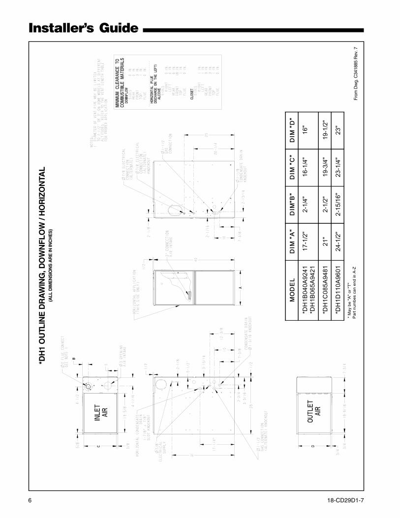
18-CD29D1-7 7
Installer’s Guide
UPFLOWFURNACE
CASEDCOIL
SCREWS(BOTH SIDES)
STANDOFFS(BOTH SIDES)
STANDOFFS (4) DRILL SCREWS (4)
FOR VERTICALINSTALLATIONS:
1
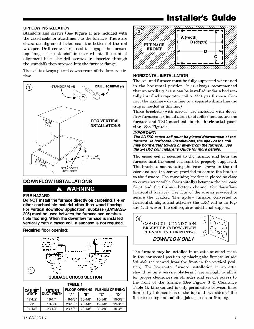
HORIZONTAL INSTALLATIONThe coil and furnace must be fully supported when usedin the horizontal position. It is always recommendedthat an auxiliary drain pan be installed under a horizon-tally installed evaporator coil or 95% gas furnace. Con-nect the auxiliary drain line to a separate drain line (notrap is needed in this line).Three brackets (with screws) are included with down-flow furnaces for installation to stabilize and secure thefurnace and TXC cased coil in the horizontal posi-tion. See Figure 4.IMPORTANT:The 2/4TXC cased coil must be placed downstream of thefurnace. In horizontal installations, the apex of the coilmay point either toward or away from the furnace. Seethe 2/4TXC coil Installer's Guide for more details.
The cased coil is secured to the furnace and both thefurnace and the cased coil must be properly supported.The brackets mount using the rear screws on the coilcase and use the screws provided to secure the bracketto the furnace. The remaining bracket is placed as closeto center as possible (horizontally) between the coil casefront and the furnace bottom channel (for downflow/horizontal furnace). Use four of the screws provided tosecure the bracket. The upflow furnace, converted tohorizontal, aligns and attaches the TXC coil as in Fig-ure 1. However, the coil requires additional support.
UPFLOW INSTALLATIONStandoffs and screws (See Figure 1) are included withthe cased coils for attachment to the furnace. There areclearance alignment holes near the bottom of the coilwrapper. Drill screws are used to engage the furnacetop flanges. The standoff is inserted into the cabinetalignment hole. The drill screws are inserted throughthe standoffs then screwed into the furnace flange.
The coil is always placed downstream of the furnace air-flow.
DOWNFLOW INSTALLATIONS
▲ WARNING!FIRE HAZARDDo NOT install the furnace directly on carpeting, tile orother combustible material other than wood flooring.For vertical downflow application, subbase (BAYBASE-205) must be used between the furnace and combus-tible flooring. When the downflow furnace is installedvertically with a cased coil, a subbase is not required.
Required floor opening:
SUBBASE CROSS SECTION
TABLE 1
CABINETWIDTH
RETURNDUCT WIDTH
FLOOR OPENING PLENUM OPENING
"A" "B" "C" "D"17-1/2" 16-1/4" 16-5/8" 20-1/8" 15-5/8" 19-3/8"
21" 19-3/4" 20-1/8" 20-1/8" 19-1/8" 19-3/8"
24-1/2" 23-1/4" 23-5/8" 20-1/8" 22-5/8" 19-3/8"
2
123456789012345678901234567890121234567890123456712345678901234567890123456789012123456789012345671234567890123456789012345678901212345678901234567123456789012345678901234567890121234567890123456712345678901234567890123456789012123456789012345671234567890123456789012345678901212345678901234567123456789012345678901234567890121234567890123456712345678901234567890123456789012123456789012345671234567890123456789012345678901212345678901234567123456789012345678901234567890121234567890123456712345678901234567890123456789012123456789012345671234567890123456789012345678901212345678901234567123456789012345678901234567890121234567890123456712345678901234567890123456789012123456789012345671234567890123456789012345678901212345678901234567123456789012345678901234567890121234567890123456712345678901234567890123456789012123456789012345671234567890123456789012345678901212345678901234567123456789012345678901234567890121234567890123456712345678901234567890123456789012123456789012345671234567890123456789012345678901212345678901234567
FURNACEFRONT
A (width)B (depth)
CD
3
CASED COIL CONNECTIONBRACKET FOR DOWNFLOWFURNACE IN HORIZONTAL
DOWNFLOW ONLY
4
The furnace may be installed in an attic or crawl spacein the horizontal position by placing the furnace on theleft side (as viewed from the front in the vertical posi-tion). The horizontal furnace installation in an atticshould be on a service platform large enough to allowfor proper clearances on all sides and service access tothe front of the furnace (See Figure 3 & ClearanceTable 1). Line contact is only permissible between linesformed by intersections of the top and two sides of thefurnace casing and building joists, studs, or framing.
8 18-CD29D1-7
Installer’s Guide
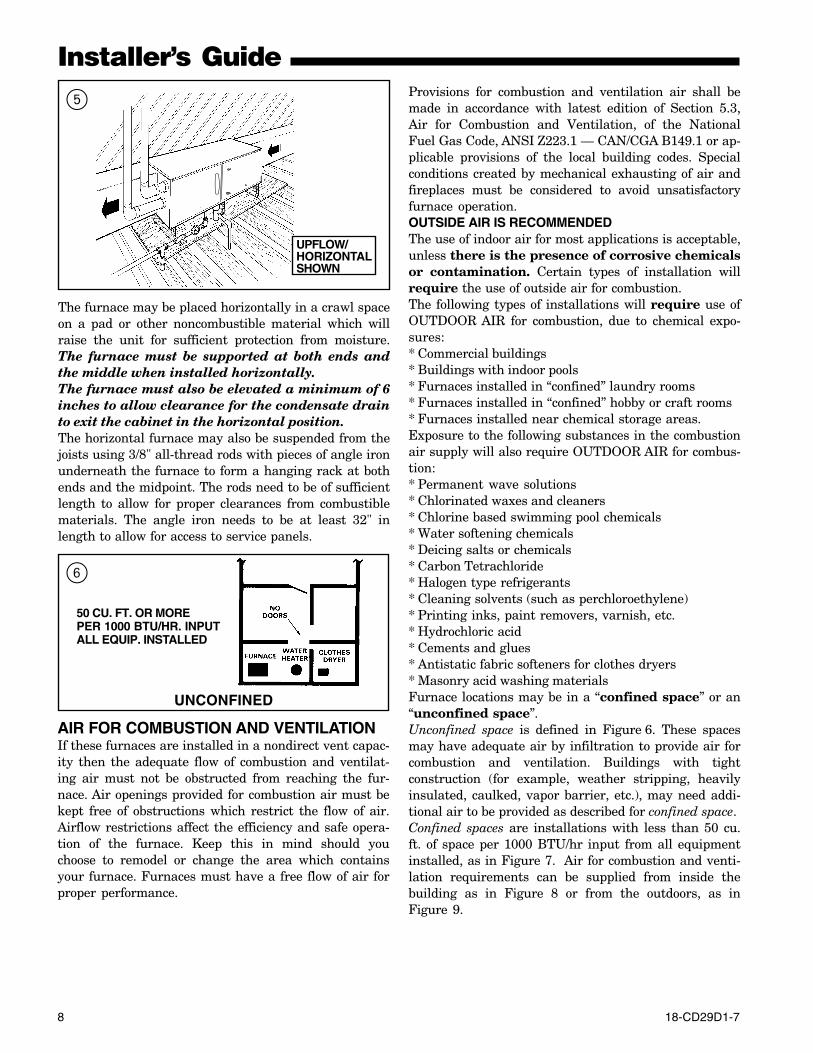
The furnace may be placed horizontally in a crawl spaceon a pad or other noncombustible material which willraise the unit for sufficient protection from moisture.The furnace must be supported at both ends andthe middle when installed horizontally.The furnace must also be elevated a minimum of 6inches to allow clearance for the condensate drainto exit the cabinet in the horizontal position.The horizontal furnace may also be suspended from thejoists using 3/8" all-thread rods with pieces of angle ironunderneath the furnace to form a hanging rack at bothends and the midpoint. The rods need to be of sufficientlength to allow for proper clearances from combustiblematerials. The angle iron needs to be at least 32" inlength to allow for access to service panels.
Provisions for combustion and ventilation air shall bemade in accordance with latest edition of Section 5.3,Air for Combustion and Ventilation, of the NationalFuel Gas Code, ANSI Z223.1 — CAN/CGA B149.1 or ap-plicable provisions of the local building codes. Specialconditions created by mechanical exhausting of air andfireplaces must be considered to avoid unsatisfactoryfurnace operation.OUTSIDE AIR IS RECOMMENDEDThe use of indoor air for most applications is acceptable,unless there is the presence of corrosive chemicalsor contamination. Certain types of installation willrequire the use of outside air for combustion.The following types of installations will require use ofOUTDOOR AIR for combustion, due to chemical expo-sures:* Commercial buildings* Buildings with indoor pools* Furnaces installed in “confined” laundry rooms* Furnaces installed in “confined” hobby or craft rooms* Furnaces installed near chemical storage areas.Exposure to the following substances in the combustionair supply will also require OUTDOOR AIR for combus-tion:* Permanent wave solutions* Chlorinated waxes and cleaners* Chlorine based swimming pool chemicals* Water softening chemicals* Deicing salts or chemicals* Carbon Tetrachloride* Halogen type refrigerants* Cleaning solvents (such as perchloroethylene)* Printing inks, paint removers, varnish, etc.* Hydrochloric acid* Cements and glues* Antistatic fabric softeners for clothes dryers* Masonry acid washing materialsFurnace locations may be in a “confined space” or an“unconfined space”.Unconfined space is defined in Figure 6. These spacesmay have adequate air by infiltration to provide air forcombustion and ventilation. Buildings with tightconstruction (for example, weather stripping, heavilyinsulated, caulked, vapor barrier, etc.), may need addi-tional air to be provided as described for confined space.Confined spaces are installations with less than 50 cu.ft. of space per 1000 BTU/hr input from all equipmentinstalled, as in Figure 7. Air for combustion and venti-lation requirements can be supplied from inside thebuilding as in Figure 8 or from the outdoors, as inFigure 9.
50 CU. FT. OR MOREPER 1000 BTU/HR. INPUTALL EQUIP. INSTALLED
UNCONFINED
6
AIR FOR COMBUSTION AND VENTILATIONIf these furnaces are installed in a nondirect vent capac-ity then the adequate flow of combustion and ventilat-ing air must not be obstructed from reaching the fur-nace. Air openings provided for combustion air must bekept free of obstructions which restrict the flow of air.Airflow restrictions affect the efficiency and safe opera-tion of the furnace. Keep this in mind should youchoose to remodel or change the area which containsyour furnace. Furnaces must have a free flow of air forproper performance.
5
UPFLOW/HORIZONTALSHOWN
18-CD29D1-7 9
Installer’s Guide
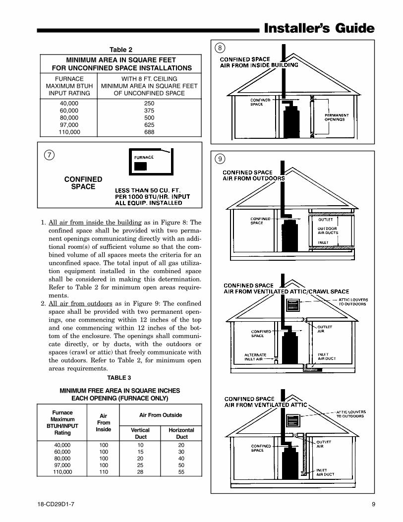
1. All air from inside the building as in Figure 8: Theconfined space shall be provided with two perma-nent openings communicating directly with an addi-tional room(s) of sufficient volume so that the com-bined volume of all spaces meets the criteria for anunconfined space. The total input of all gas utiliza-tion equipment installed in the combined spaceshall be considered in making this determination.Refer to Table 2 for minimum open areas require-ments.
2. All air from outdoors as in Figure 9: The confinedspace shall be provided with two permanent open-ings, one commencing within 12 inches of the topand one commencing within 12 inches of the bot-tom of the enclosure. The openings shall communi-cate directly, or by ducts, with the outdoors orspaces (crawl or attic) that freely communicate withthe outdoors. Refer to Table 2, for minimum openareas requirements.
TABLE 3
MINIMUM FREE AREA IN SQUARE INCHESEACH OPENING (FURNACE ONLY)
FurnaceMaximum
BTUH/INPUTRating
AirFromInside
Air From Outside
Vertical Duct
Horizontal Duct
40,00060,00080,00097,000110,000
100100100100110
1015202528
2030405055
8
9
CONFINEDSPACE
7
Table 2
MINIMUM AREA IN SQUARE FEET FOR UNCONFINED SPACE INSTALLATIONS
FURNACEMAXIMUM BTUHINPUT RATING
WITH 8 FT. CEILINGMINIMUM AREA IN SQUARE FEET
OF UNCONFINED SPACE
40,00060,00080,00097,000110,000
250375500625688
10 18-CD29D1-7
Installer’s GuideDUCT CONNECTIONSAir duct systems should be installed in accordance withstandards for air conditioning systems, National FireProtection Association Pamphlet No. 90. They shouldbe sized in accordance with ACCA Manual D or which-ever is applicable.Central furnaces, when used in connection with coolingunits, shall be installed in parallel or on the upstreamside of the cooling coil to avoid condensation in the heatexchanger. With a parallel flow arrangement, the damp-ers or other means used to control flow of air shall beadequate to prevent chilled air from entering the fur-nace, and if manually operated, must be equipped withmeans to prevent operation of either unit unless thedamper is in full heat or cool position.On any job, flexible connections of nonflammable mate-rial may be used for return air and discharge connectionsto prevent transmission of vibration. Though these unitshave been specifically designed for quiet, vibration freeoperation, air ducts can act as sounding boards and could,if poorly installed, amplify the slightest vibration to theannoyance level.When the furnace is located in a utility room adjacentto the living area, the system should be carefully de-signed with returns to minimize noise transmissionthrough the return air grille. Although these furnacesare designed with large blowers operating at moderatespeeds, any blower moving a high volume of air willproduce audible noise which could be objectionablewhen the unit is located very close to a living area. It isoften advisable to route the return air ducts under thefloor or through the attic. Such design permits the in-stallation of air return remote from the living area(i.e. central hall).When the furnace is installed so that the supply ductscarry air circulated by the furnace to areas outside thespace containing the furnace, the return air shall alsobe handled by a duct(s) sealed to the furnace and termi-nating outside the space containing the furnace.
RETURN AIR DUCT CONNECTION
NOTE:On upflow 5 or 6 ton airflow models where theairflow requirement exceeds 1800 CFM - Models willrequire return air openings and filters on: (1) bothsides; or (2) one side and the bottom; or (3) just thebottom.
All return air duct systems should provide for installa-tion of return air filters.
1. Determine the appropriate position to set thefurnace in order to connect to the existing supplyand return ductwork.
2. For side return installations on upflow models,remove the insulation around the opening in theblower compartment.
NOTE:Minimum return air temperature is 55° F.
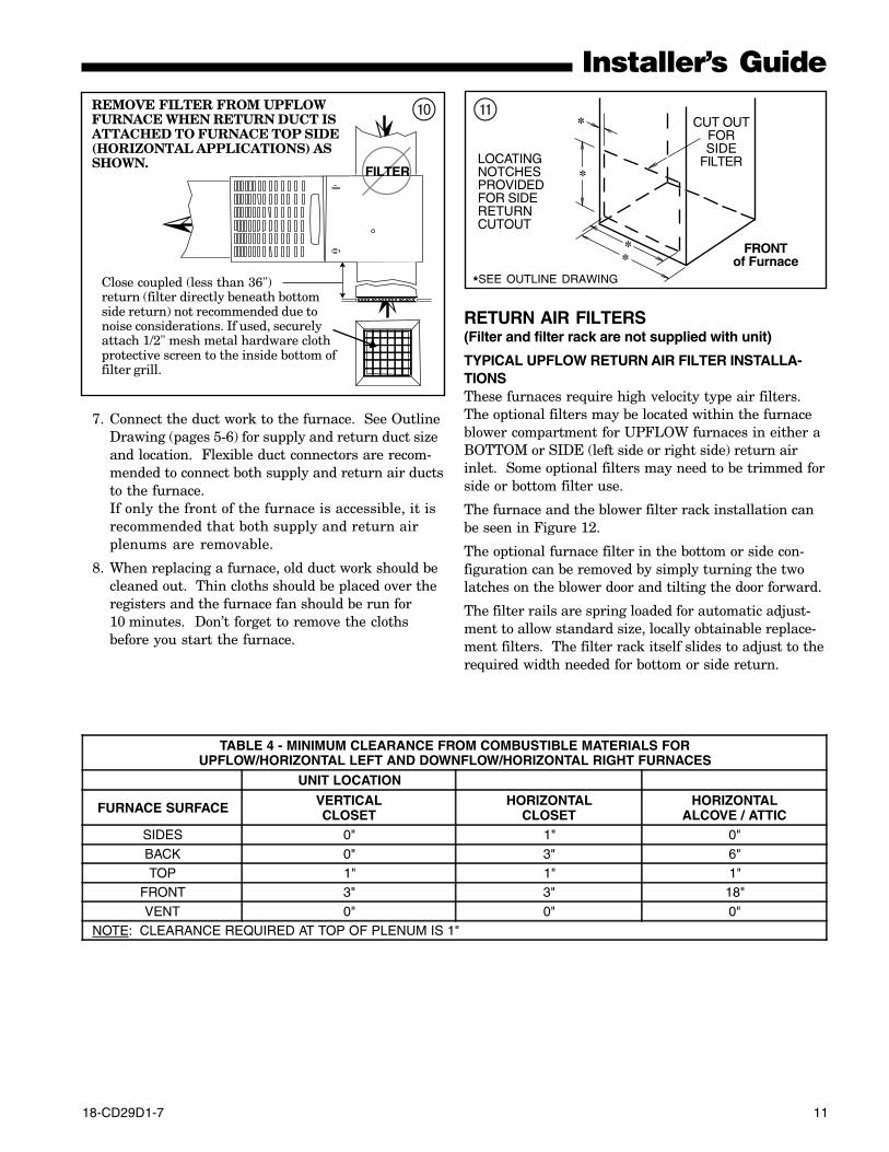
3. The side panels on upflow furnaces include locatingnotches which may be used as guides for cutting anopening for return air. Refer to Figure 11 and theoutline drawing on pages 5-6 for duct connectiondimensions for various furnaces.
4. If a 3/4" flange is to be used for attaching the airinlet duct, add to cut where indicated by dashedlines in Figure 11. Cut corners diagonally and bendoutward to form flange.
5. If flanges are not required, and a filter frame isinstalled, cut along knockout guidelines.
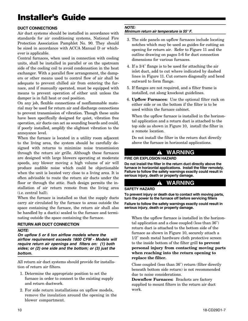
6. Upflow Furnaces: Use the optional filter rack oneither side or on the bottom if the filter is to beused within the furnace cabinet.
When the upflow furnace is installed in the horizon-tal application and a return duct is attached to thetop side as shown in Figure 10, install the filter ina remote location.
Do not install the filter in the return duct directlyabove the furnace in horizontal applications.
When the upflow furnace is installed in the horizon-tal application and a close coupled (less than 36")return duct is attached to the bottom side of thefurnace as shown in Figure 10, securely attach a1/2" mesh metal hardware cloth protective screento the inside bottom of the filter grill to preventpersonal injury from contacting moving partswhen reaching into the return opening toreplace the filter.
Close coupled (less than 36") return (filter directlybeneath bottom side return) is not recommendeddue to noise considerations.Downflow Furnaces: Brackets are factorysupplied to mount filters in the return air ductwork.
▲ WARNING!FIRE OR EXPLOSION HAZARD
Do not install the filter in the return duct directly above thefurnace in horizontal applications. Install the filter remotely.Failure to follow the safety warnings exactly could result inserious injury, death or property damage.
▲ WARNING!SAFETY HAZARD
To prevent injury or death due to contact with moving parts,turn the power to the furnace off before servicing filters
Failure to follow the safety warnings exactly could result inserious injury, death or property damage.
18-CD29D1-7 11
Installer’s Guide
FILTER
REMOVE FILTER FROM UPFLOWFURNACE WHEN RETURN DUCT ISATTACHED TO FURNACE TOP SIDE(HORIZONTAL APPLICATIONS) ASSHOWN.
Close coupled (less than 36")return (filter directly beneath bottomside return) not recommended due tonoise considerations. If used, securelyattach 1/2" mesh metal hardware clothprotective screen to the inside bottom offilter grill.
0
*SEE OUTLINE DRAWING
q
LOCATINGNOTCHESPROVIDEDFOR SIDERETURNCUTOUT
*
**
* CUT OUTFORSIDE
FILTER
FRONTof Furnace
7. Connect the duct work to the furnace. See OutlineDrawing (pages 5-6) for supply and return duct sizeand location. Flexible duct connectors are recom-mended to connect both supply and return air ductsto the furnace.If only the front of the furnace is accessible, it isrecommended that both supply and return airplenums are removable.
8. When replacing a furnace, old duct work should becleaned out. Thin cloths should be placed over theregisters and the furnace fan should be run for10 minutes. Don’t forget to remove the clothsbefore you start the furnace.
RETURN AIR FILTERS(Filter and filter rack are not supplied with unit)
TYPICAL UPFLOW RETURN AIR FILTER INSTALLA-TIONSThese furnaces require high velocity type air filters.The optional filters may be located within the furnaceblower compartment for UPFLOW furnaces in either aBOTTOM or SIDE (left side or right side) return airinlet. Some optional filters may need to be trimmed forside or bottom filter use.
The furnace and the blower filter rack installation canbe seen in Figure 12.
The optional furnace filter in the bottom or side con-figuration can be removed by simply turning the twolatches on the blower door and tilting the door forward.
The filter rails are spring loaded for automatic adjust-ment to allow standard size, locally obtainable replace-ment filters. The filter rack itself slides to adjust to therequired width needed for bottom or side return.
TABLE 4 - MINIMUM CLEARANCE FROM COMBUSTIBLE MATERIALS FORUPFLOW/HORIZONTAL LEFT AND DOWNFLOW/HORIZONTAL RIGHT FURNACES
UNIT LOCATION
FURNACE SURFACE VERTICALCLOSET
HORIZONTALCLOSET
HORIZONTALALCOVE / ATTIC
SIDES 0" 1" 0"BACK 0" 3" 6"TOP 1" 1" 1"
FRONT 3" 3" 18"VENT 0" 0" 0"
NOTE: CLEARANCE REQUIRED AT TOP OF PLENUM IS 1"
12 18-CD29D1-7
Installer’s Guide
VIEWENGAGEMENTHOLE DETAIL
(Typical both sidesand blower deck)
Blower DeckEngagement
Hole
NOTE: The narrow 14.5" width furnace cabinet prevents useof the filter rack for right side return. Pre-drill clearanceholes and then attach filter clips with the screws provided.The filter clip with the leaf spring mounts in the rear of thecabinet
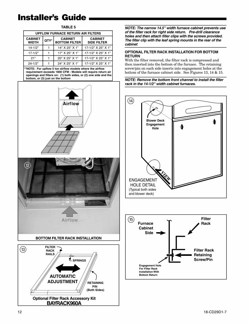
OPTIONAL FILTER RACK INSTALLATION FOR BOTTOMRETURNWith the filter removed, the filter rack is compressed andthen inserted into the bottom of the furnace. The retainingscrew/pin on each side inserts into engagement holes at thebottom of the furnace cabinet side. See Figures 13, 14 & 15.
NOTE: Remove the bottom front channel to install the filterrack in the 14-1/2" width cabinet furnaces.
FilterRackFurnace
CabinetSide
Filter RackRetainingScrew/Pin
Engagement Hole For
Bottom Return
Filter RackInstallation With
r
t
Optional Filter Rack Accessory Kit
e
Airf low
TABLE 5
UPFLOW FURNACE RETURN AIR FILTERS
CABINETWIDTH QTY* CABINET
BOTTOM FILTERCABINET
SIDE FILTER
14-1/2" 1 14" X 25" X 1" 17-1/2" X 25" X 1"
17-1/2" 1 17" X 25" X 1" 17-1/2" X 25" X 1"
21" 1 20" X 25" X 1" 17-1/2" X 25" X 1"
24-1/2" 1 24" X 25" X 1" 17-1/2" X 25" X 1"
**NOTE: For upflow 5 ton airflow models where the airflow requirement exceeds 1800 CFM - Models will require return air openings and filters on: (1) both sides, or (2) one side and the bottom, or (3) just on the bottom
BAYRACK960A
BOTTOM FILTER RACK INSTALLATION
Airf low
w
18-CD29D1-7 13
Installer’s Guide
FilterRackAssembly
FurnaceBlowerDeck
Filter RackRetainingScrew/Pin
Engagement Hole For
Return
Filter RackInstallation WithSide
FurnaceCabinet
Side
BLOWERDECK
u
BOTTOM ENGAGEMENT
Bottom Panel
FilterRack
FurnaceCabinet
Side
Filter RackRetainingScrew/Pin
Engagement Hole For
Bottom Return
Filter RackInstallation With
y
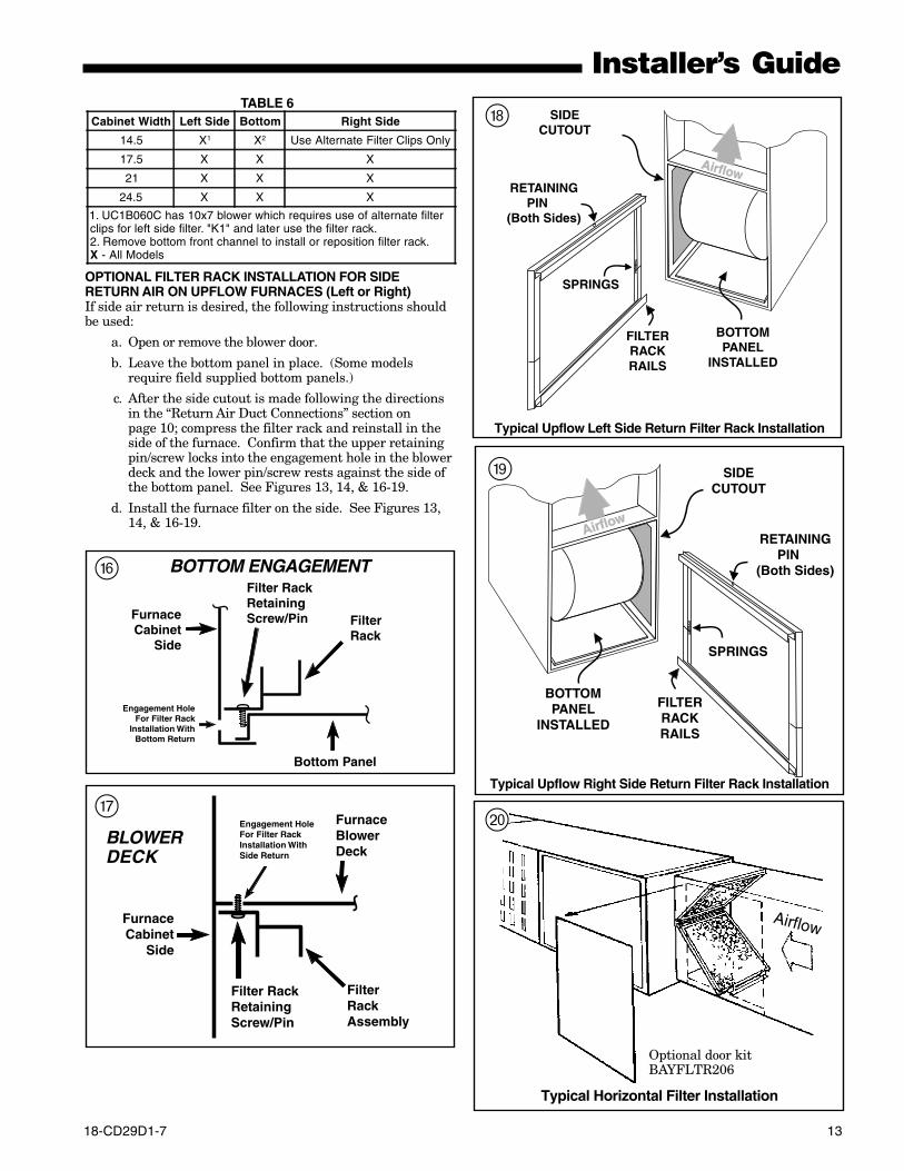
OPTIONAL FILTER RACK INSTALLATION FOR SIDERETURN AIR ON UPFLOW FURNACES (Left or Right)If side air return is desired, the following instructions shouldbe used:
a. Open or remove the blower door.
b. Leave the bottom panel in place. (Some modelsrequire field supplied bottom panels.)
c. After the side cutout is made following the directionsin the “Return Air Duct Connections” section onpage 10; compress the filter rack and reinstall in theside of the furnace. Confirm that the upper retainingpin/screw locks into the engagement hole in the blowerdeck and the lower pin/screw rests against the side ofthe bottom panel. See Figures 13, 14, & 16-19.
d. Install the furnace filter on the side. See Figures 13,14, & 16-19.
Airflow
p
Typical Horizontal Filter Installation
TABLE 6Cabinet Width Left Side Bottom Right Side
14.5 X1 X2 Use Alternate Filter Clips Only
17.5 X X X
21 X X X
24.5 X X X
1. UC1B060C has 10x7 blower which requires use of alternate filterclips for left side filter. "K1" and later use the filter rack.2. Remove bottom front channel to install or reposition filter rack.X - All Models
RETAININGPIN
(Both Sides)
SPRINGS
SIDECUTOUT
FILTERRACKRAILS
BOTTOMPANEL
INSTALLED
AirflowAirflow
Typical Upflow Left Side Return Filter Rack Installation
i
RETAININGPIN
(Both Sides)
SPRINGS
SIDECUTOUT
FILTERRACKRAILS
BOTTOMPANEL
INSTALLED
AirflowAirflow
o
Typical Upflow Right Side Return Filter Rack Installation
Optional door kitBAYFLTR206
14 18-CD29D1-7
Installer’s Guide
REAR
SIDE
CUT-OUT
ALTERNATE FILTERCLIPS LOCATION
Optional horizontal filter conversion kits are BAYFLTR203for 17 1/2" width cabinets, BAYFLTR204 for 21" widthcabinets, and BAYFLTR205 for 24" width cabinets. Theseinclude filters and brackets necessary for horizontal filters.In addition, optional door kit BAYFLTR206 is also available.See Figures 20.
RETURN AIR FILTERS FOR UPFLOW FURNACEIN HORIZONTAL CONFIGURATIONWhen the Upflow Furnace is installed in a horizontal configu-ration, the filter must never be installed inside or outside thecabinet directly above the blower assembly. See Figure 10(page 11). Remote filter grilles may be used for homeownerconvenience or the filters may be installed in the duct workupstream of the furnace. See Figures 20 (page 13).
ALTERNATE UPFLOWFILTER CLIP / BRACKET INSTALLATION - KIT09224
1. Determine the location to be used. The furnace cabinethas dimples for location of the alternate furnace clips(Side return only). Pre-drill clearance holes with a3/16" drill. Bottom return holes are pre-drilled.
2. Install the clips in front and rear of the desired locationusing the screws provided. The filter clip with the leafspring mounts in the rear of the cabinet. See Figure 21.
a
UNITSIZE
RETURN AIR
BOTTOM SIDE
14-1/2" CUT ON LINE DO NOT CUT
17-1/2" DO NOT CUT DO NOT CUT
21" DO NOT CUT CUT ON LINE
24-1/2" DO NOT CUT CUT ON LINE
TABLE 7
INSTALLING THE OPTIONAL FILTERThe filter may need to be cut to fit the unit depending on thelocation of the return air filter.
A score line and the words “CUT HERE” are located on theend of the filter. If your application requires cutting the filter,do so as indicted by the score mark.
Airflow
Airflow
s
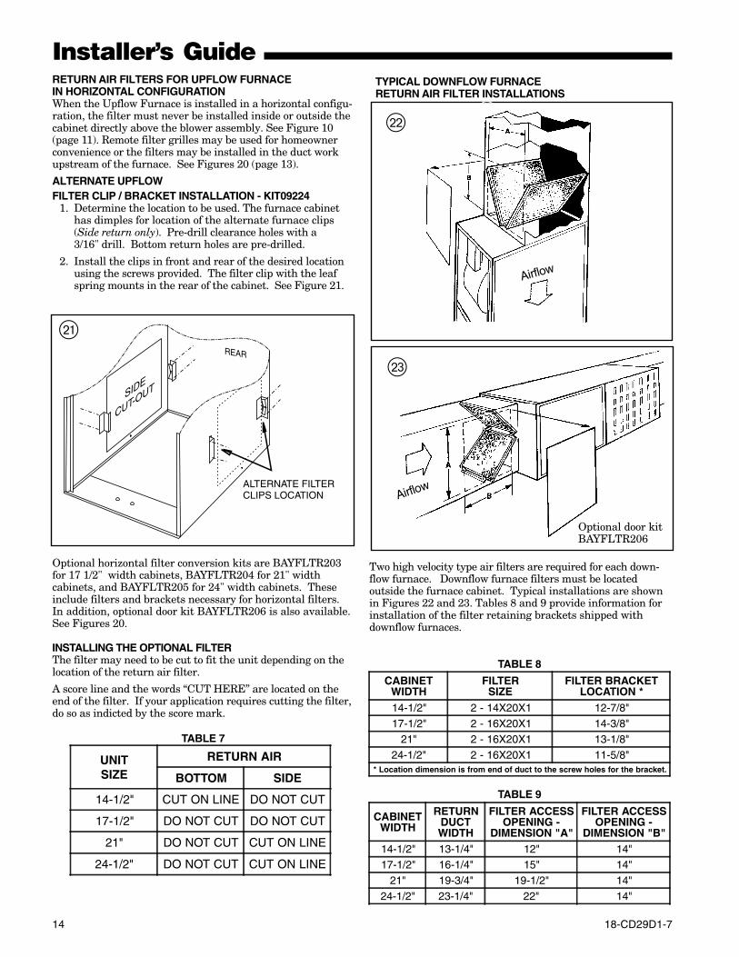
Two high velocity type air filters are required for each down-flow furnace. Downflow furnace filters must be locatedoutside the furnace cabinet. Typical installations are shownin Figures 22 and 23. Tables 8 and 9 provide information forinstallation of the filter retaining brackets shipped withdownflow furnaces.
d
i
TYPICAL DOWNFLOW FURNACERETURN AIR FILTER INSTALLATIONS
TABLE 8
TABLE 9
CABINETWIDTH
RETURNDUCTWIDTH
FILTER ACCESSOPENING -
DIMENSION "A"
FILTER ACCESSOPENING -
DIMENSION "B"14-1/2" 13-1/4" 12" 14"17-1/2" 16-1/4" 15" 14"
21" 19-3/4" 19-1/2" 14"24-1/2" 23-1/4" 22" 14"
CABINETWIDTH
FILTERSIZE
FILTER BRACKETLOCATION *
14-1/2" 2 - 14X20X1 12-7/8"17-1/2" 2 - 16X20X1 14-3/8"
21" 2 - 16X20X1 13-1/8"24-1/2" 2 - 16X20X1 11-5/8"
* Location dimension is from end of duct to the screw holes for the bracket.
Optional door kitBAYFLTR206
18-CD29D1-7 15
Installer’s GuideGENERAL VENTING The following steps shall be followed with each appli-
ance remaining connected to the common venting sys-tem placed in operation, while the other appliances re-maining connected to the common venting system arenot in operation.
1. Seal any unused openings in the common ventingsystem.
2. Visually inspect the venting system for proper sizeand horizontal pitch and determine there is noblockage or restriction, leakage, corrosion or otherdeficiencies which could cause an unsafe condition.
3. Insofar as is practical, close all building doors andwindows and all doors between the space in whichthe appliances remaining connected to the commonventing system are located and other spaces of thebuilding. Turn on clothes dryers and any appliancesnot connected to the common venting system. Turnon any exhaust fans, such as range hoods and bath-room exhausts, so they will operate at maximumspeed. Do not operate a summer exhaust fan, closefireplace dampers.
4. Follow the lighting instructions. Place the appliancebeing inspected in operation. Adjust thermostat soappliance will operate continuously.
5. Test for spillage at the draft hood relief opening af-ter 5 minutes of main burner operation. Use theflame of a match or candle.
6. After it has been determined that each appliance re-maining connected to the common venting systemproperly vents when tested as outlined above, re-turn door, windows, exhaust fans, fireplace dampersand any other gas-burning appliance to their previ-ous conditions of use.
If improper venting is observed during any of the abovetests, the remaining common venting system must becorrected. Correction of the remaining common ventsystem should be done by referring to the latest editionof the National Fuel Gas Code (ANSI Z223.1) • CAN/CGA B149.1 Installation Codes or “Exhibit J” ofANSI Z21.47 • CAN/ CGA-2.3 Standards. The followingare general steps to be used to correct or resize a re-maining vent system when a furnace which may not becommon vented is removed from the system:
a. Determine the Btu per hour input of all remain-ing appliances attached to the venting system.
b. Determine the diameter, rise, and lateral of theexisting venting system, as well as quantity andtype of bends.
c. Use the appropriate tables in the latest edition ofthe National Fuel Gas Code (ANSI Z223.1 •CAN/ CGA B149.1 Installation Codes or “ExhibitJ” of ANSI Z21.47 • CAN/ CGA-2.3 Standards.“Exhibit J” includes examples and drawings oftypical venting systems.
IMPORTANT:These furnaces may be installed as Direct Vent (sealedcombustion) or as Nondirect vent (single pipe). The fur-naces are shipped DIRECT VENT with sealed combus-tion.
For DIRECT VENT APPLICATION: The furnaces must bevented to the exterior of the house and combustion airMUST come through the inlet air pipe FROM OUTSIDEAIR.
For NONDIRECT VENT APPLICATION: The furnace shallbe vented to the exterior of the house, but combustion airmay enter from the surrounding area as long as combus-tion air requirements are met. (See AIR FOR COMBUS-TION AND VENTILATION)
THIS FURNACE MUST BE VENTED TO THE OUT-DOORS.THESE FURNACES ARE INDUCED DRAFT VENTEDAND MUST NOT BE CONNECTED TO ANY VENTSERVING ANOTHER APPLIANCE. PLEASE NOTETHAT THESE FURNACES USE POSITIVE-PRESSURE VENT SYSTEMS.Proper venting is essential to obtain maximum effi-ciency from a condensing furnace. Proper installationof the vent system is necessary to assure drainage ofthe condensate and prevent deterioration of the ventsystem.American Gas Association has certified the design ofcondensing furnaces for a minimum of 0" clearancefrom combustible materials with a single wall plasticvent pipe.The recommended system is assembled from 2", 2-1/2",or 3" plastic pipe and fittings (See Table 10, page 16).Where the system is routed to the outdoors through anexisting masonry chimney containing flue productsfrom another gas appliance, or where required by localcodes, then 3" venting of Type 29-4C stainless steelmust be used in place of PVC material.These furnaces have been classified as CATEGORY IVfurnaces in accordance with the latest edition ofANSI Z21.47 • CAN/ CGA-2.3 Standards. Category IVfurnaces operate with positive vent pressure and with avent gas temperature less than 140°F above thedewpoint. These conditions require special venting sys-tems, which must be gas tight and water tight.
NOTE:When an existing furnace is removed from a ventingsystem serving other gas appliances, the venting sys-tem is likely to be too large to properly vent the re-maining attached appliances.
16 18-CD29D1-7
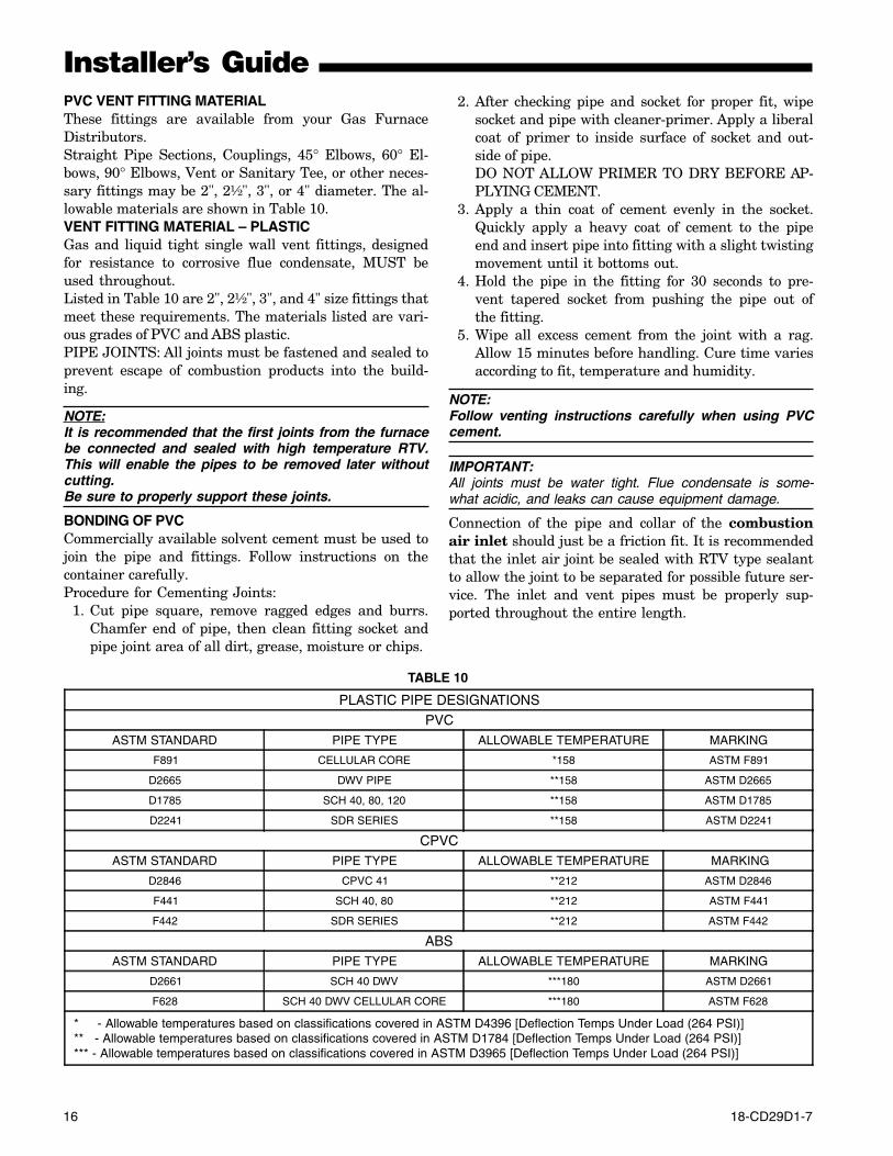
Installer’s GuidePVC VENT FITTING MATERIALThese fittings are available from your Gas FurnaceDistributors.Straight Pipe Sections, Couplings, 45° Elbows, 60° El-bows, 90° Elbows, Vent or Sanitary Tee, or other neces-sary fittings may be 2", 2½", 3", or 4" diameter. The al-lowable materials are shown in Table 10.VENT FITTING MATERIAL – PLASTICGas and liquid tight single wall vent fittings, designedfor resistance to corrosive flue condensate, MUST beused throughout.Listed in Table 10 are 2", 2½", 3", and 4" size fittings thatmeet these requirements. The materials listed are vari-ous grades of PVC and ABS plastic.PIPE JOINTS: All joints must be fastened and sealed toprevent escape of combustion products into the build-ing.
NOTE:It is recommended that the first joints from the furnacebe connected and sealed with high temperature RTV.This will enable the pipes to be removed later withoutcutting.Be sure to properly support these joints.
BONDING OF PVCCommercially available solvent cement must be used tojoin the pipe and fittings. Follow instructions on thecontainer carefully.Procedure for Cementing Joints:
1. Cut pipe square, remove ragged edges and burrs.Chamfer end of pipe, then clean fitting socket andpipe joint area of all dirt, grease, moisture or chips.
TABLE 10
PLASTIC PIPE DESIGNATIONS
PVCASTM STANDARD PIPE TYPE ALLOWABLE TEMPERATURE MARKING
F891 CELLULAR CORE *158 ASTM F891
D2665 DWV PIPE **158 ASTM D2665
D1785 SCH 40, 80, 120 **158 ASTM D1785
D2241 SDR SERIES **158 ASTM D2241
CPVCASTM STANDARD PIPE TYPE ALLOWABLE TEMPERATURE MARKING
D2846 CPVC 41 **212 ASTM D2846
F441 SCH 40, 80 **212 ASTM F441
F442 SDR SERIES **212 ASTM F442
ABSASTM STANDARD PIPE TYPE ALLOWABLE TEMPERATURE MARKING
D2661 SCH 40 DWV ***180 ASTM D2661
F628 SCH 40 DWV CELLULAR CORE ***180 ASTM F628
* - Allowable temperatures based on classifications covered in ASTM D4396 [Deflection Temps Under Load (264 PSI)] ** - Allowable temperatures based on classifications covered in ASTM D1784 [Deflection Temps Under Load (264 PSI)] *** - Allowable temperatures based on classifications covered in ASTM D3965 [Deflection Temps Under Load (264 PSI)]
2. After checking pipe and socket for proper fit, wipesocket and pipe with cleaner-primer. Apply a liberalcoat of primer to inside surface of socket and out-side of pipe.DO NOT ALLOW PRIMER TO DRY BEFORE AP-PLYING CEMENT.
3. Apply a thin coat of cement evenly in the socket.Quickly apply a heavy coat of cement to the pipeend and insert pipe into fitting with a slight twistingmovement until it bottoms out.
4. Hold the pipe in the fitting for 30 seconds to pre-vent tapered socket from pushing the pipe out ofthe fitting.
5. Wipe all excess cement from the joint with a rag.Allow 15 minutes before handling. Cure time variesaccording to fit, temperature and humidity.
NOTE:Follow venting instructions carefully when using PVCcement.
IMPORTANT:All joints must be water tight. Flue condensate is some-what acidic, and leaks can cause equipment damage.
Connection of the pipe and collar of the combustionair inlet should just be a friction fit. It is recommendedthat the inlet air joint be sealed with RTV type sealantto allow the joint to be separated for possible future ser-vice. The inlet and vent pipes must be properly sup-ported throughout the entire length.
18-CD29D1-7 17
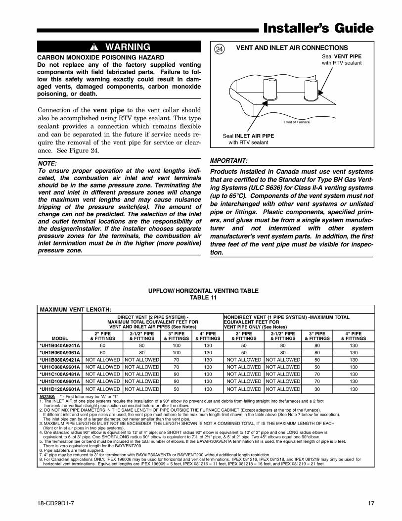
Installer’s Guide
Seal VENT PIPEwith RTV sealant
Seal INLET AIR PIPEwith RTV sealant
Front of Furnace
VENT AND INLET AIR CONNECTIONSf
Connection of the vent pipe to the vent collar shouldalso be accomplished using RTV type sealant. This typesealant provides a connection which remains flexibleand can be separated in the future if service needs re-quire the removal of the vent pipe for service or clear-ance. See Figure 24.
NOTE:To ensure proper operation at the vent lengths indi-cated, the combustion air inlet and vent terminalsshould be in the same pressure zone. Terminating thevent and inlet in different pressure zones will changethe maximum vent lengths and may cause nuisancetripping of the pressure switch(es). The amount ofchange can not be predicted. The selection of the inletand outlet terminal locations are the responsibility ofthe designer/installer. If the installer chooses separatepressure zones for the terminals, the combustion airinlet termination must be in the higher (more positive)pressure zone.
MAXIMUM VENT LENGTH:
MODEL
DIRECT VENT (2 PIPE SYSTEM) -MAXIMUM TOTAL EQUIVALENT FEET FORVENT AND INLET AIR PIPES (See Notes)
NONDIRECT VENT (1 PIPE SYSTEM) -MAXIMUM TOTAL EQUIVALENT FEET FOR VENT PIPE ONLY (See Notes)
2" PIPE& FITTINGS
2-1/2" PIPE& FITTINGS
3" PIPE& FITTINGS
4" PIPE& FITTINGS
2" PIPE& FITTINGS
2-1/2" PIPE& FITTINGS
3" PIPE& FITTINGS
4" PIPE& FITTINGS
*UH1B040A9241A 60 80 100 130 50 80 80 130
*UH1B060A9361A 60 80 100 130 50 80 80 130
*UH1B080A9421A NOT ALLOWED NOT ALLOWED 70 130 NOT ALLOWED NOT ALLOWED 50 130
*UH1C080A9601A NOT ALLOWED NOT ALLOWED 70 130 NOT ALLOWED NOT ALLOWED 50 130
*UH1C100A9481A NOT ALLOWED NOT ALLOWED 90 130 NOT ALLOWED NOT ALLOWED 70 130
*UH1D100A9601A NOT ALLOWED NOT ALLOWED 90 130 NOT ALLOWED NOT ALLOWED 70 130
*UH1D120A9601A NOT ALLOWED NOT ALLOWED 50 130 NOT ALLOWED NOT ALLOWED 30 130
NOTES: * - First letter may be "A" or "T" 1. The INLET AIR of one pipe systems require the installation of a 90° elbow (to prevent dust and debris from falling straight into thefurnace) and a 2 foot horizontal or vertical straight pipe section connected before or after the elbow. 2. DO NOT MIX PIPE DIAMETERS IN THE SAME LENGTH OF PIPE OUTSIDE THE FURNACE CABINET (Except adapters at the top of the furnace). If different inlet and vent pipe sizes are used, the vent pipe must adhere to the maximum length limit shown in the table above (See Note 7 below for exception). The inlet pipe can be of a larger diameter, but never smaller than the vent pipe. 3. MAXIMUM PIPE LENGTHS MUST NOT BE EXCEEDED! THE LENGTH SHOWN IS NOT A COMBINED TOTAL, IT IS THE MAXIMUM LENGTH OF EACH (Vent or Inlet air pipes in two pipe systems). 4. One standard radius 90° elbow is equivalent to 12' of 4" pipe; one SHORT radius 90° elbow is equivalent to 10' of 3" pipe and one LONG radius elbow is equivalent to 6' of 3" pipe. One SHORT/LONG radius 90° elbow is equivalent to 7½' of 2½" pipe, & 5' of 2" pipe. Two 45° elbows equal one 90°elbow. 5. The termination tee or bend must be included in the total number of elbows. If the BAYAIR30AVENTA termination kit is used, the equivalent length of pipe is 5 feet. There is zero equivalent length for the BAYVENT200. 6. Pipe adapters are field supplied. 7. 4" pipe may be reduced to 3" for termination with BAYAIR30AVENTA or BAYVENT200 without additional length restriction. 8. For Canadian applications ONLY, IPEX 196006 may be used for horizontal and vertical terminations. IPEX 081216, IPEX 081218, and IPEX 081219 may only be used for horizontal vent terminations. Equivalent lengths are IPEX 196009 = 5 feet, IPEX 081216 = 11 feet, IPEX 081218 = 16 feet, and IPEX 081219 = 21 feet.
UPFLOW/ HORIZONTAL VENTING TABLETABLE 11
IMPORTANT:
Products installed in Canada must use vent systemsthat are certified to the Standard for Type BH Gas Vent-ing Systems (ULC S636) for Class II-A venting systems(up to 65°C). Components of the vent system must notbe interchanged with other vent systems or unlistedpipe or fittings. Plastic components, specified prim-ers, and glues must be from a single system manufac-turer and not intermixed with other systemmanufacturer's vent system parts. In addition, the firstthree feet of the vent pipe must be visible for inspec-tion.
▲ WARNING!CARBON MONOXIDE POISONING HAZARDDo not replace any of the factory supplied ventingcomponents with field fabricated parts. Failure to fol-low this safety warning exactly could result in dam-aged vents, damaged components, carbon monoxidepoisoning, or death.
18 18-CD29D1-7
Installer’s Guide
Vent onlyto outside
Air Inlet
B
A
A (0-2') or greaterB (0-2') or greaterA+B = 2' minimum
UPFLOW FURNACE
SINGLE PIPE VENTING
g
V
D
EE
V
G
INSIDECORNER DETAIL
BL V
V
FIXED CLOSED
OPERABLE
F
B
C
VFIXED
CLOSEDV
V
VB
B
B
A
X
J
B
H
I
V X
K
M
V VENT TERMINAL X AIR SUPPLY INLET AREA WHERE TERMINAL IS NOT PERMITTED
OPERABLE
h
VENT CLEARANCESSee Tables 9 & 10
MAXIMUM VENT LENGTH:
MODEL
DIRECT VENT (2 PIPE SYSTEM) -MAXIMUM TOTAL EQUIVALENT FEET FORVENT AND INLET AIR PIPES (See Notes)
NONDIRECT VENT (1 PIPE SYSTEM) -MAXIMUM TOTAL EQUIVALENT FEET FOR
VENT PIPE ONLY (See Notes)2" PIPE
& FITTINGS2-1/2" PIPE& FITTINGS
3" PIPE& FITTINGS
4" PIPE& FITTINGS
2" PIPE& FITTINGS
2-1/2" PIPE& FITTINGS
3" PIPE& FITTINGS
4" PIPE& FITTINGS
*DH1B040A9241A 60 80 100 130 50 80 80 130
*DH1B065A9421A 45 80 100 130 40 80 80 130
*DH1C085A9481A NOT ALLOWED 80 100 130 NOT ALLOWED 80 80 130
*DH1D110A9601A NOT ALLOWED 15 60 130 NOT ALLOWED NOT ALLOWED 50 130 NOTES: * - First letter may be "A" or "T" 1. The INLET AIR of one pipe systems require the installation of a 90° elbow (to prevent dust and debris from falling straight into thefurnace) and a 2 foot horizontal or vertical straight pipe section connected before or after the elbow. 2. DO NOT MIX PIPE DIAMETERS IN THE SAME LENGTH OF PIPE OUTSIDE THE FURNACE CABINET (Except adapters at the top of the furnace). If different inlet and vent pipe sizes are used, the vent pipe must adhere to the maximum length limit shown in the table above (See Note 7 below for exception). The inlet pipe can be of a larger diameter, but never smaller than the vent pipe. 3. MAXIMUM PIPE LENGTHS MUST NOT BE EXCEEDED! THE LENGTH SHOWN IS NOT A COMBINED TOTAL, IT IS THE MAXIMUM LENGTH OF EACH (Vent or Inlet air pipes in two pipe systems). 4. One standard radius 90° elbow is equivalent to 12' of 4" pipe; one SHORT radius 90° elbow is equivalent to 10' of 3" pipe and one LONG radius elbow is equivalent to 6' of 3" pipe. One SHORT/LONG radius 90° elbow is equivalent to 7½' of 2½" pipe, & 5' of 2" pipe. Two 45° elbows equal one 90°elbow. 5. The termination tee or bend must be included in the total number of elbows. If the BAYAIR30AVENTA termination kit is used, the equivalent length of pipe is 5 feet. There is zero equivalent length for the BAYVENT200B. 6. Pipe adapters are field supplied. 7. 4" pipe may be reduced to 3" for termination with BAYAIR30AVENTA or BAYVENT200B without additional length restriction. 8. For Canadian applications ONLY, IPEX 196006 may be used for horizontal and vertical terminations. IPEX 081216, IPEX 081218, and IPEX 081219 may only be used for horizontal vent terminations. Equivalent lengths are IPEX 196009 = 5 feet, IPEX 081216 = 11 feet, IPEX 081218 = 16 feet, and IPEX 081219 = 21 feet.
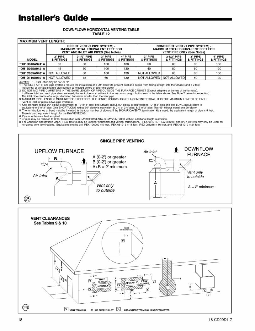
DOWNFLOW/ HORIZONTAL VENTING TABLETABLE 12
Vent onlyto outside
Air Inlet
AA = 2' minimum
DOWNFLOWFURNACE
18-CD29D1-7 19
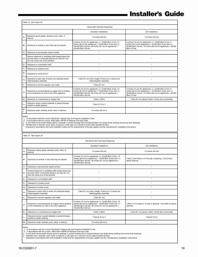
Installer’s GuideTable 13 - See Figure 22
Direct Vent Terminal Clearances
Canadian Installations US Installations
A=Clearance above grade, veranda, porch, deck, orbalcony
12 inches (30 cm) 12 inches (30 cm)
B= Clearance to window or door that may be opened
6 inches (15 cm) for appliances =/< 10,000 Btuh (3 kw), 12inches (30 cm) for appliances > 10,000 Btuh (3 kw) and =/<100,000 Btuh (30 kw), 36 inches (91 cm) for appliances >100,000 Btuh (30 kw)
6 inches (15 cm) for appliances =/< 10,000 Btuh (3 kw), 9inches (23 cm) for appliances > 10,000 Btuh (3 kw) and =/<50,000 Btuh (15 kw), 12 inches (30 cm) for appliances > 50,000Btuh (15 kw)
C= Clearance to permanently closed window * *
D=Vertical clearance to ventilated soffit located above theterminal within a horizontal distance of 2 feet (61 cm)from the center line of the terminal
* *
E= Clearance to unventilated soffit * *
F= Clearance to outside corner * *
G-=
Clearance to inside corner * *
H=Clearance to each side of center line extended abovemeter/regulator assembly
3 feet (91 cm) with a height 15 feet (4.5 m) above themeter/regulator assembly
*
I= Clearance to service regulator vent outlet 3 feet (91 cm) *
J=Clearance to nonmechanical air supply inlet to buildingor the combustion air inlet to any other appliance
6 inches (15 cm) for appliances =/< 10,000 Btuh (3 kw), 12inches (30 cm) for appliances > 10,000 Btuh (3 kw) and =/<100,000 Btuh (30 kw), 36 inches (91 cm) for appliances >100,000 Btuh (30 kw)
6 inches (15 cm) for appliances =/< 10,000 Btuh (3 kw), 9inches (23 cm) for appliances > 10,000 Btuh (3 kw) and =/<50,000 Btuh (15 kw), 12 inches (30 cm) for appliances > 50,000Btuh (15 kw)
K= Clearance to a mechanical air supply inlet 6 feet (1.83m) 3 feet (91 cm) above if within 10 feet (3m) horizontally
L=Clearance above a paved sidewalk or paved drivewaylocated on public property
7 feet (2.13 m) † *
M-=
Clearance under veranda, porch, deck, or balcony `12 inches (30 cm) ‡ *
Notes: 1. In accordance with the current CSA B149.1 Natural Gas and Propane Installation Code. 2. In accordance with the current ANSI Z223.1/NFPA 54 National Fuel Gas Code.†. A vent shall not terminate directly above a sidewalk or paved driveway that is located between two single family dwelling and serves both dwellings.‡. Pemitted only if veranda, porch, deck, or balcony is fully open on a minimum of two sides beneath the floor. * Clearance in accordance with local installation codes and the requirements of the gas supplier and the manufacturer's Installation Instructions.
Table 14 - See Figure 22
Non-Direct Vent Terminal Clearances
Canadian Installations US Installations
A=Clearance above grade, veranda, porch, deck, orbalcony
12 inches (30 cm) 12 inches (30 cm)
B= Clearance to window or door that may be opened
6 inches (15 cm) for appliances =/< 10,000 Btuh (3 kw), 12inches (30 cm) for appliances > 10,000 Btuh (3 kw) and =/<100,000 Btuh (30 kw), 36 inches (91 cm) for appliances >100,000 Btuh (30 kw)
4 feet (1.2m) below or to the side of opening; 1 foot (0.3m)above opening.
C= Clearance to permanently closed window * *
D=Vertical clearance to ventilated soffit located above theterminal within a horizontal distance of 2 feet (61 cm)from the center line of the terminal
* *
E= Clearance to unventilated soffit * *
F= Clearance to outside corner * *
G= Clearance to inside corner * *
H=Clearance to each side of center line extended abovemeter/regulator assembly
3 feet (91 cm) with a height 15 feet (4.5 m) above themeter/regulator assembly
*
I= Clearance to service regulator vent outlet 3 feet (91 cm) *
J=Clearance to nonmechanical air supply inlet to buildingor the combustion air inlet to any other appliance
6 inches (15 cm) for appliances =/< 10,000 Btuh (3 kw), 12inches (30 cm) for appliances > 10,000 Btuh (3 kw) and =/<100,000 Btuh (30 kw), 36 inches (91 cm) for appliances >100,000 Btuh (30 kw)
4 feet (1.2 m) below or to side of opening; 1 foot (300 m) aboveopening
K= Clearance to a mechanical air supply inlet 6 feet (1.83m) 3 feet (91 cm) above if within 10 feet (3m) horizontally
L=Clearance above a paved sidewalk or paved drivewaylocated on public property
7 feet (2.13 m) † 7 feet (2.13 m)
M= Clearance under veranda, porch, deck, or balcony `12 inches (30 cm) ‡ *
Notes: 1. In accordance with the current CSA B149.1 Natural Gas and Propane Installation Code. 2. In accordance with the current ANSI Z223.1/NFPA 54 National Fuel Gas Code.†. A vent shall not terminate directly above a sidewalk or paved driveway that is located between two single family dwelling and serves both dwellings.‡. Pemitted only if veranda, porch, deck, or balcony is fully open on a minimum of two sides beneath the floor. * Clearance in accordance with local installation codes and the requirements of the gas supplier and the manufacturer's Installation Instructions.
20 18-CD29D1-7
Installer’s Guide
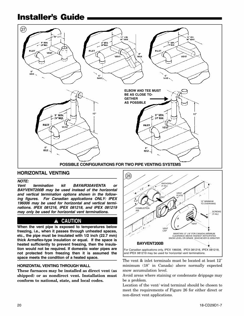
HORIZONTAL VENTING
NOTE:Vent termination kit BAYAIR30AVENTA orBAYVENT200B may be used instead of the horizontaland vertical termination options shown in the follow-ing figures. For Canadian applications ONLY: IPEX196006 may be used for horizontal and vertical termi-nations. IPEX 081216, IPEX 081218, and IPEX 081219may only be used for horizontal vent terminations.
▲ CAUTION!When the vent pipe is exposed to temperatures belowfreezing, i.e., when it passes through unheated spaces,etc., the pipe must be insulated with 1/2 inch (22.7 mm)thick Armaflex-type insulation or equal. If the space isheated sufficiently to prevent freezing, then the insula-tion would not be required. If domestic water pipes arenot protected from freezing then it is assumed thespace meets the condition of a heated space.
HORIZONTAL VENTING THROUGH WALLThese furnaces may be installed as direct vent (asshipped) or as nondirect vent. Installation mustconform to national, state, and local codes.
POSSIBLE CONFIGURATIONS FOR TWO PIPE VENTING SYSTEMS
ELBOW AND TEE MUSTBE AS CLOSE TO-GETHERAS POSSIBLE
j
The vent & inlet terminals must be located at least 12"minimum (18" in Canada) above normally expectedsnow accumulation level.Avoid areas where staining or condensate drippage maybe a problem.Location of the vent/ wind terminal should be chosen tomeet the requirements of Figure 26 for either direct ornon-direct vent applications.
VENT
COMBUSTIONAIR
VENT
VENTPLATE
VENTCAP
12" MINIMUMTO OVERHANG
MAINTAIN 12" (18" FOR CANADA) MINIMUMCLEARANCE ABOVE HIGHEST ANTICIPATED
SNOW LEVEL OR GRADE WHICHEVER IS GREATER
SCREWS(4 req.)
ANCHORS(4 req.)
7.2"
3.2"
BAYVENT200B
k
For Canadian applications only, IPEX 196006, IPEX 081216, IPEX 081218,and IPEX 081219 may be used for horizontal vent terminations.
18-CD29D1-7 21
Installer’s GuidePITCH – Venting through the wall must maintain 1/4"per foot pitched upward to insure that condensatedrains back to the furnace.FLUE GAS DEGRADATION – The moisture contentof the flue gas may have a detrimental effect on somebuilding materials. This can be avoided by using theroof or chimney venting option. When wall venting isused on any surface that can be affected by this mois-ture, it is recommended that a corrosion resistantshield (24 inches square) be used behind the vent termi-nal. This shield can be wood, plastic, sheet metal, etc.Also, silicone caulk all cracks, seams and joints within 3feet of the vent terminal.COMBUSTIBLE MATERIAL WALLA minimum clearance of 1" to combustible materialsmust be maintained when using single wall stainlesssteel venting. See Figure 30.
COMBUSTION AIR VENT
12" MIN TO OVERHANG
1"
MAINTAIN 12 IN(18 IN. FOR CANADA)MINIMUM CLEARANCEABOVE HIGHEST ANTICIPATED SNOWLEVEL OR GRADEWHICHEVER IS GREATER
1 2"
BAYAIR30AVENTA(Sidewall)
l
Shield material to be a minimum of 24 gauge stainlessor aluminized sheet metal. Minimum dimensions are12"x12". Shield must be fastened to both inside and out-side of wall. Use screws or anchor type fasteners suitedto the outside or inside wall surfaces.NONCOMBUSTIBLE MATERIAL WALLThe hole through the wall must be large enough tomaintain pitch of vent and properly seal.Use cement mortar seal on inside and outside of wall.See Figure 31.VENTING THROUGH THE ROOFWhen penetrating roof with a 2" PVC vent pipe, a 2"electrical conduit flashing may be used for a weathertight seal. Lubricate flexible seal on flashing before PVCpipe is pushed through the seal. (Field Supplied)
NOTE:No vent cap as shown in Figure 35 is the preferredmethod for vertical vent termination in extremely coldclimates.In extreme climate conditions, insulate the exposedpipe above the roof line with Armaflex type insulation.
x SUPPORT HORIZONTAL PIPE EVERY 3'0" WITH THE FIRST SUPPORT AS CLOSETO THE FURNACE AS POSSIBLE.INDUCED DRAFT BLOWER, HOUSING,AND FURNACE MUST NOT SUPPORTTHE WEIGHT OF THE FLUE PIPE.
COUPLING(PLASTICVENTING) STUD
PVC WALLMOUNT FLANGE (OPTIONAL)
APPROVEDTERMINATION
1” CLEARANCE(AIR SPACE)
VENTING THROUGH COMBUSTIBLE WALLS Pitch - 1/4 Inch Per Foot
CLEARANCE (0” ACCEPTABLE FOR PVC VENT PIPE)(1” ACCEPTABLE FOR TYPE 29-4C STAINLESS STEEL VENT PIP
12” MINIMUM ABOVENORMALLY EXPECTEDSNOW ACCUMULATIONLEVEL
6 IN. MIN.(TO JOINT)
COUPLING(PLASTICVENTING)
PVC WALLMOUNT FLANGE (OPTIONAL)
APPROVEDTERMINATION
CEMENTMORTAR SEAL INSIDE & OUTSIDE
VENTING THROUGH NON-COMBUSTIBLE WALLS Pitch - 1/4 Inch Per Foot
12” MINIMUM ABOVENORMALLY EXPECTEDSNOW ACCUMULATIONLEVEL
6 IN. MIN.(TO JOINT)
;
z
For Canadian applications only, IPEX 196006, IPEX 081216, IPEX 081218,and IPEX 081219 may be used for horizontal vent terminations.
22 18-CD29D1-7
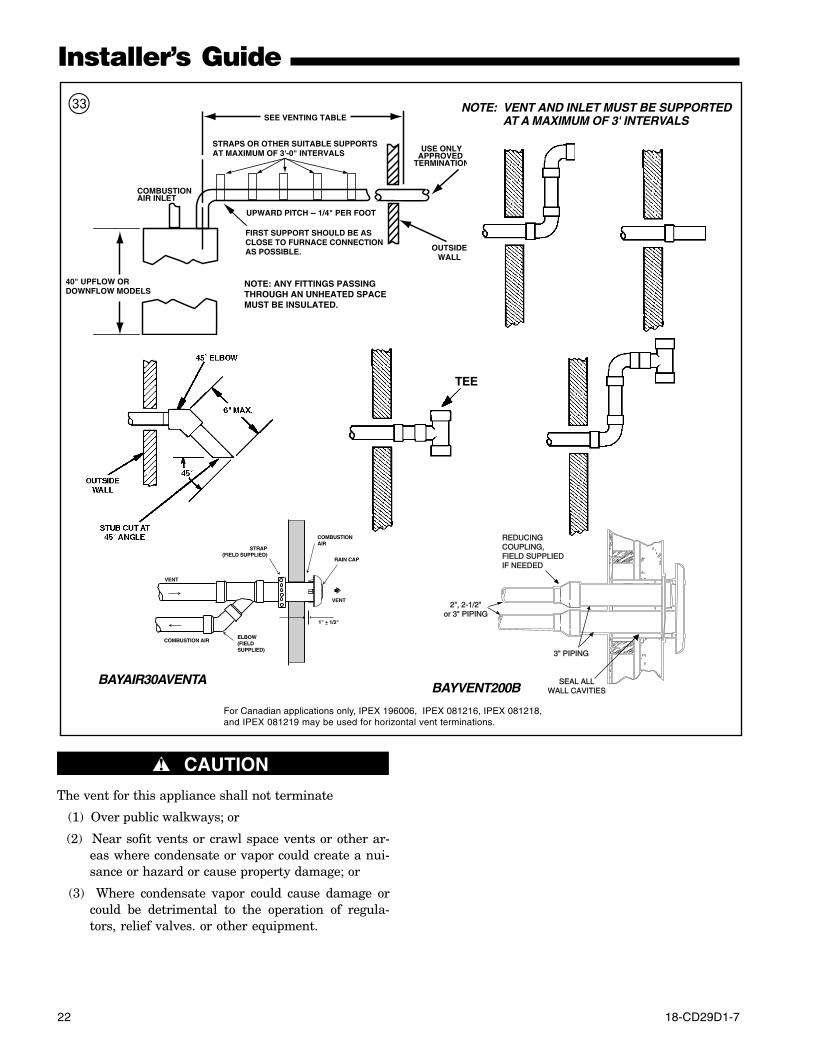
Installer’s Guide
NOTE: VENT AND INLET MUST BE SUPPORTEDAT A MAXIMUM OF 3' INTERVALS
40" UPFLOW ORDOWNFLOW MODELS
SEE VENTING TABLE
OUTSIDEWALL
NOTE: ANY FITTINGS PASSINGTHROUGH AN UNHEATED SPACEMUST BE INSULATED.
FIRST SUPPORT SHOULD BE ASCLOSE TO FURNACE CONNECTIONAS POSSIBLE.
UPWARD PITCH -- 1/4" PER FOOT
STRAPS OR OTHER SUITABLE SUPPORTSAT MAXIMUM OF 3'-0" INTERVALS
COMBUSTIONAIR INLET
USE ONLYAPPROVED
TERMINATION
TEE
RAIN CAP
COMBUSTION AIR
STRAP(FIELD SUPPLIED)
COMBUSTIONAIR
VENT
ELBOW(FIELD SUPPLIED)
VENT
1" + 1/2"
BAYAIR30AVENTA
3" PIPING
2", 2-1/2"or 3" PIPING
REDUCING COUPLING,FIELD SUPPLIEDIF NEEDED
SEAL ALLWALL CAVITIESBAYVENT200B
c
▲ CAUTION!
The vent for this appliance shall not terminate
(1) Over public walkways; or
(2) Near sofit vents or crawl space vents or other ar-eas where condensate or vapor could create a nui-sance or hazard or cause property damage; or
(3) Where condensate vapor could cause damage orcould be detrimental to the operation of regula-tors, relief valves. or other equipment.
For Canadian applications only, IPEX 196006, IPEX 081216, IPEX 081218,and IPEX 081219 may be used for horizontal vent terminations.
18-CD29D1-7 23
Installer’s Guide
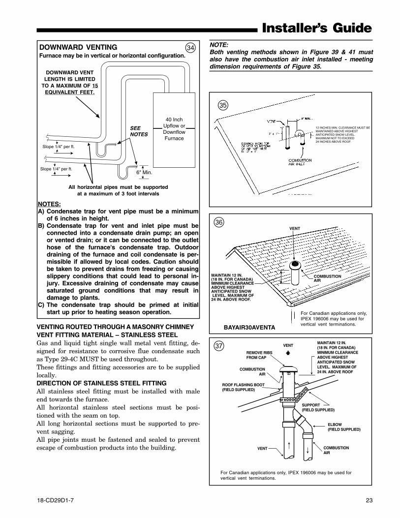
VENTING ROUTED THROUGH A MASONRY CHIMNEYVENT FITTING MATERIAL – STAINLESS STEELGas and liquid tight single wall metal vent fitting, de-signed for resistance to corrosive flue condensate suchas Type 29-4C MUST be used throughout.These fittings and fitting accessories are to be suppliedlocally.DIRECTION OF STAINLESS STEEL FITTINGAll stainless steel fitting must be installed with maleend towards the furnace.All horizontal stainless steel sections must be posi-tioned with the seam on top.All long horizontal sections must be supported to pre-vent sagging.All pipe joints must be fastened and sealed to preventescape of combustion products into the building.
NOTE:Both venting methods shown in Figure 39 & 41 mustalso have the combustion air inlet installed - meetingdimension requirements of Figure 35.
b
MAINTAIN 12 IN.(18 IN. FOR CANADA)MINIMUM CLEARANCEABOVE HIGHESTANTICIPATED SNOW LEVEL. MAXIMUM OF24 IN. ABOVE ROOF.
VENT
COMBUSTIONAIR
n
BAYAIR30AVENTA
REMOVE RIBSFROM CAP
COMBUSTION AIR
ROOF FLASHING BOOT(FIELD SUPPLIED)
COMBUSTIONAIR
VENT
ELBOW(FIELD SUPPLIED)
MAINTAIN 12 IN.(18 IN. FOR CANADA)MINIMUM CLEARANCEABOVE HIGHEST ANTICIPATED SNOWLEVEL. MAXIMUM OF24 IN. ABOVE ROOF
SUPPORT(FIELD SUPPLIED)
VENTm
6" Min.
40 Inch Upflow or Downflow Furnace
Slope 1/4" per ft.
Slope 1/4" per ft.
All horizontal pipes must be supportedat a maximum of 3 foot intervals
DOWNWARD VENTINGFurnace may be in vertical or horizontal configuration.
v
NOTES:A) Condensate trap for vent pipe must be a minimum
of 6 inches in height.B) Condensate trap for vent and inlet pipe must be
connected into a condensate drain pump; an openor vented drain; or it can be connected to the outlethose of the furnace's condensate trap. Outdoordraining of the furnace and coil condensate is per-missible if allowed by local codes. Caution shouldbe taken to prevent drains from freezing or causingslippery conditions that could lead to personal in-jury. Excessive draining of condensate may causesaturated ground conditions that may result indamage to plants.
C) The condensate trap should be primed at initialstart up prior to heating season operation.
DOWNWARD VENTLENGTH IS LIMITED
TO A MAXIMUM OF 15EQUIVALENT FEET.
For Canadian applications only, IPEX 196006 may be used forvertical vent terminations.
12 INCHES MIN. CLEARANCE MUST BEMAINTAINED ABOVE HIGHESTANTICIPATED SNOW LEVEL. MAXIMUM NOT TO EXCEED 24 INCHES ABOVE ROOF.
For Canadian applications only,IPEX 196006 may be used forvertical vent terminations.
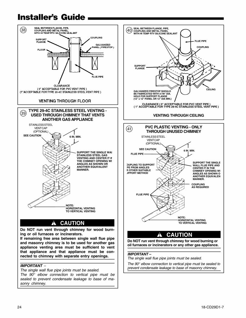
24 18-CD29D1-7
Installer’s Guide
,
GALVANIZED FIRESTOP SHOULDBE FABRICATED WITH 3-7/8" DIA.HOLE FOR SUPPORT FLANGE(12" x 12" PANEL OR 12" DIA MIN.)
VENTING THROUGH CEILING
CEILING
SUPPORTFLANGE
FLUE PIPE
COUPLING
SEAL BETWEEN FLANGE, PIPE,COUPLING AND METAL PANELWITH HI TEMP RTV SILICONE SEALANT
CLEARANCE ( 0" ACCEPTABLE FOR PVC VENT PIPE )( 1" ACCEPTABLE FOR TYPE 29-4C STAINLESS STEEL VENT PIPE )
/
SUPPORT THE SINGLE WALSTAINLESS STEEL GASVENTING AND CENTER IT INTHE CHIMNEY OPENING WITANGLES AS SHOWN OR ANOTHER EQUIVALENTMANNER.
NOTE:HORIZONTAL VENTINGTO VERTICAL VENTING
6 IN. MIN.SEE CAUTION
STAINLESSSTEELVENT CAP
TYPE 29-4C STAINLESS STEEL VENTING -USED THROUGH CHIMNEY THAT VENTS
ANOTHER GAS APPLIANCESTAINLESS STEEL
VENT CAP(OPTIONAL)
▲ CAUTION!Do NOT run vent through chimney for wood burn-ing or oil furnaces or incinerators.If remaining free area between single wall flue pipeand masonry chimney is to be used for another gasappliance venting area must be sufficient to ventthat appliance and that appliance must be con-nected to chimney with separate entry openings.
IMPORTANT –The single wall flue pipe joints must be sealed.The 90° elbow connection to vertical pipe must besealed to prevent condensate leakage to base of ma-sonry chimney.
.
SUPPORT THE SINGLEWALL FLUE PIPE AND CENTER IT IN THE CHIMNEY OPENING WIANGLES AS SHOWN OANOTHER EQUIVALENMANNER.
NOTE:HORIZONTAL VENTING TO VERTICAL VENTING
6 IN. MIN.
STAINLESSSTEELVENT CAP
SEE CAUTION
FLUE PIPE
COUPLINGAS REQUIRED
FLUE PIPE
OUPLING TO SUPPORT PE FROM ANGLES R OTHER SUITABLEUPPORT METHOD
▲ CAUTION!Do NOT run vent through chimney for wood burning oroil furnaces or incinerators or any other gas appliance.
IMPORTANT –The single wall flue pipe joints must be sealed.
The 90° elbow connection to vertical pipe must be sealed toprevent condensate leakage to base of masonry chimney.
PVC PLASTIC VENTING - ONLYTHROUGH UNUSED CHIMNEY
STAINLESS STEELVENT CAP
(OPTIONAL)
!
18-CD29D1-7 25
Installer’s GuideIMPORTANT:
The Commonwealth of Massachusetts requires compliancewith regulation 248 CMR 4.00 and 5.00 for installation ofthrough – the – wall vented gas appliances as follows:
For all side wall horizontally vented gas fueled equipmentinstalled in every dwelling, building or structure used inwhole or in part for residential purposes, including thoseowned or operated by the Commonwealth and where theside wall exhaust vent termination is less than seven (7)feet above finished grade in the area of the venting,including but not limited to decks and porches, thefollowing requirements shall be satisfied:1. INSTALLATION OF CARBON MONOXIDEDETECTORS. At the time of installation of the side wallhorizontal vented gas fueled equipment, the installingplumber or gasfitter shall observe that a hard wiredcarbon monoxide detector with an alarm and battery back-up is installed on the floor level where the gas equipmentis to be installed. In addition, the installing plumber orgasfitter shall observe that a battery operated or hardwired carbon monoxide detector with an alarm is installedon each additional level of the dwelling, building orstructure served by the side wall horizontal vented gasfueled equipment. It shall be the responsibility of theproperty owner to secure the services of qualified licensedprofessionals for the installation of hard wired carbonmonoxide detectorsa. In the event that the side wall horizontally ventedgas fueled equipment is installed in a crawl space or anattic, the hard wired carbon monoxide detector with alarmand battery back-up may be installed on the next adjacentfloor level.b. In the event that the requirements of thissubdivision can not be met at the time of completion ofinstallation, the owner shall have a period of thirty (30)days to comply with the above requirements; provided,however, that during said thirty (30) day period, a batteryoperated carbon monoxide detector with an alarm shall beinstalled.2. APPROVED CARBON MONOXIDEDETECTORS. Each carbon monoxide detector as requiredin accordance with the above provisions shall comply withNFPA 720 and be ANSI/UL 2034 listed and IAS certified.3. SIGNAGE. A metal or plastic identification plateshall be permanently mounted to the exterior of thebuilding at a minimum height of eight (8) feet above gradedirectly in line with the exhaust vent terminal for thehorizontally vented gas fueled heating appliance orequipment. The sign shall read, in print size no less thanone-half (1/2) inch in size, “GAS VENT DIRECTLYBELOW. KEEP CLEAR OF ALL OBSTRUCTIONS”.
4. INSPECTION. The state or local gas inspector ofthe side wall horizontally vented gas fueled equipmentshall not approve the installation unless, upon inspection,the inspector observes carbon monoxide detectors andsignage installed in accordance with the provisions of 248CMR 5.08(2)(a)1 through 4.This appliance requires a special venting system. IfBAYAIR30AVENTA or BAYVENT200B are used, a copy ofthe installation instructions for the kit shall remain withthe appliance or equipment at the completion ofinstallation. The venting system installation instructionscan be obtained from the manufacturer by writing to thefollowing address:
Residential Solutions6200 Troup HighwayTyler, TX 75707Attention: Manager of Field Operations Excellence
26 18-CD29D1-7
Installer’s GuideCONDENSATE DRAIN INSTRUCTIONSVERTICAL APPLICATIONS
▲ CAUTION!It is recommended that a drain pan be installed under thefurnace to prevent property damage or personal injury fromleaking condensate.
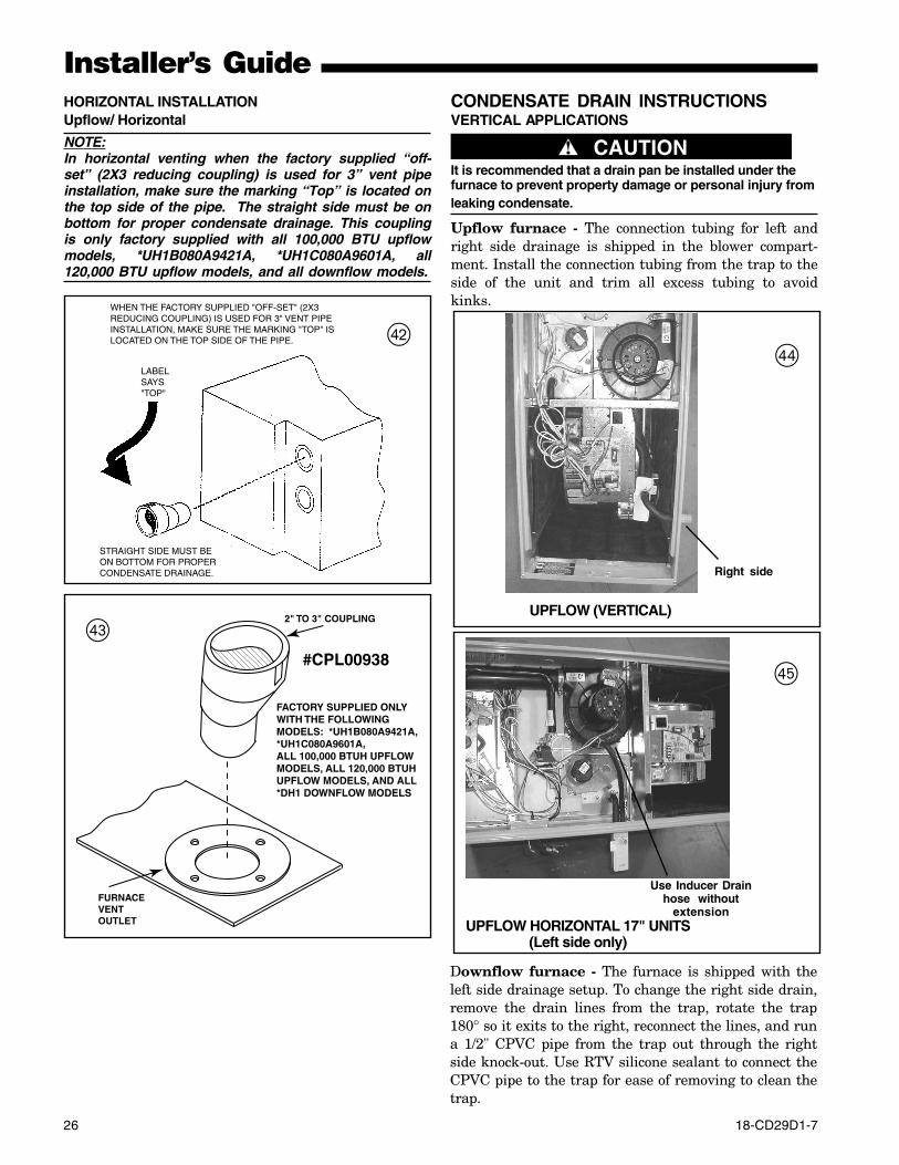
Upflow furnace - The connection tubing for left andright side drainage is shipped in the blower compart-ment. Install the connection tubing from the trap to theside of the unit and trim all excess tubing to avoidkinks.
HORIZONTAL INSTALLATIONUpflow/ Horizontal
NOTE:In horizontal venting when the factory supplied “off-set” (2X3 reducing coupling) is used for 3” vent pipeinstallation, make sure the marking “Top” is located onthe top side of the pipe. The straight side must be onbottom for proper condensate drainage. This couplingis only factory supplied with all 100,000 BTU upflowmodels, *UH1B080A9421A, *UH1C080A9601A, all120,000 BTU upflow models, and all downflow models.
LABEL SAYS "TOP"
STRAIGHT SIDE MUST BE ON BOTTOM FOR PROPER CONDENSATE DRAINAGE.
WHEN THE FACTORY SUPPLIED "OFF-SET" (2X3 REDUCING COUPLING) IS USED FOR 3" VENT PIPE INSTALLATION, MAKE SURE THE MARKING "TOP" IS LOCATED ON THE TOP SIDE OF THE PIPE.
2" TO 3" COUPLING
FURNACE VENT OUTLET
FACTORY SUPPLIED ONLY WITH THE FOLLOWING MODELS: *UH1B080A9421A,*UH1C080A9601A,ALL 100,000 BTUH UPFLOW MODELS, ALL 120,000 BTUH UPFLOW MODELS, AND ALL *DH1 DOWNFLOW MODELS
#CPL00938
UPFLOW (VERTICAL)
Right side
UPFLOW HORIZONTAL 17" UNITS(Left side only)
Use Inducer Drainhose without
extension
@$
%
#
Downflow furnace - The furnace is shipped with theleft side drainage setup. To change the right side drain,remove the drain lines from the trap, rotate the trap180° so it exits to the right, reconnect the lines, and runa 1/2" CPVC pipe from the trap out through the rightside knock-out. Use RTV silicone sealant to connect theCPVC pipe to the trap for ease of removing to clean thetrap.
18-CD29D1-7 27
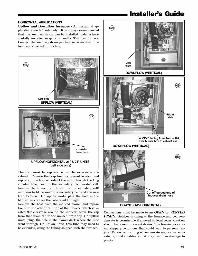
Installer’s GuideHORIZONTAL APPLICATIONSUpflow and Downflow furnaces - All horizontal ap-plications are left side only. It is always recommendedthat the auxiliary drain pan be installed under a hori-zontally installed evaporator and/or 95% gas furnace.Connect the auxiliary drain pan to a separate drain line(no trap is needed in this line).
The trap must be repositioned to the exterior of thecabinet. Remove the trap from its present location andreposition the trap outside of the unit, through the longcircular hole, next to the secondary recuperated cell.Remove the larger drain line (from the secondary cell)and trim to fit between the secondary cell and the newtrap location. On upflow units, plug the hole in theblower deck where the tube went through.Remove the hose from the induced blower and reposi-tion into the other drain tap of the inducer, which is lo-cated 90° clockwise around the inducer. Move the capfrom that drain tap to the unused drain tap. On upflowunits, plug the hole in the blower deck where the tubewent through. On upflow units, this tube may need tobe extended, using the tubing shipped with the furnace.
UPFLOW (VERTICAL)Left side
Useextensionhose here
UPFLOW HORIZONTAL 21" & 24" UNITS(Left side only)
Connections must be made to an OPEN or VENTEDDRAIN. Outdoor draining of the furnace and coil con-densate is permissible if allowed by local codes. Cautionshould be taken to prevent drains from freezing or caus-ing slippery conditions that could lead to personal in-jury. Excessive draining of condensate may cause satu-rated ground conditions that may result in damage toplants.
^
&
DOWNFLOW (VERTICAL)
Leftside
Use CPVC tubing from Trap outlet,over burner box to cabinet exit
DOWNFLOW (VERTICAL)
Rightside
Cut off curved end ofInducer drain hose
DOWNFLOW (HORIZONTAL)
*
(
)
28 18-CD29D1-7
Installer’s GuideNOTE:Use 1/2" or larger PVC or CPVC pipe and fittings as re-quired for drain connections (fittings, pipe and solventcement not provided).
NOTE:A corrosion resistant condensate pump must be usedif a pump is required for a specific drain system.
IMPORTANT:The condensate drain should be installed with provi-sions to prevent winter freeze-up of the condensatedrain line. Frozen condensate will block drains, result-ing in furnace shutdown. If the drain line cannot be in-stalled in a conditioned space, then UL listed heat tapeshould be applied as required to prevent freezing (permanufacturer’s instructions). The heat tape should berated at 5 or 6 watts per foot at 120 volts. Self-regulat-ing (preferred) or thermostatically controlled heat tapeis required.
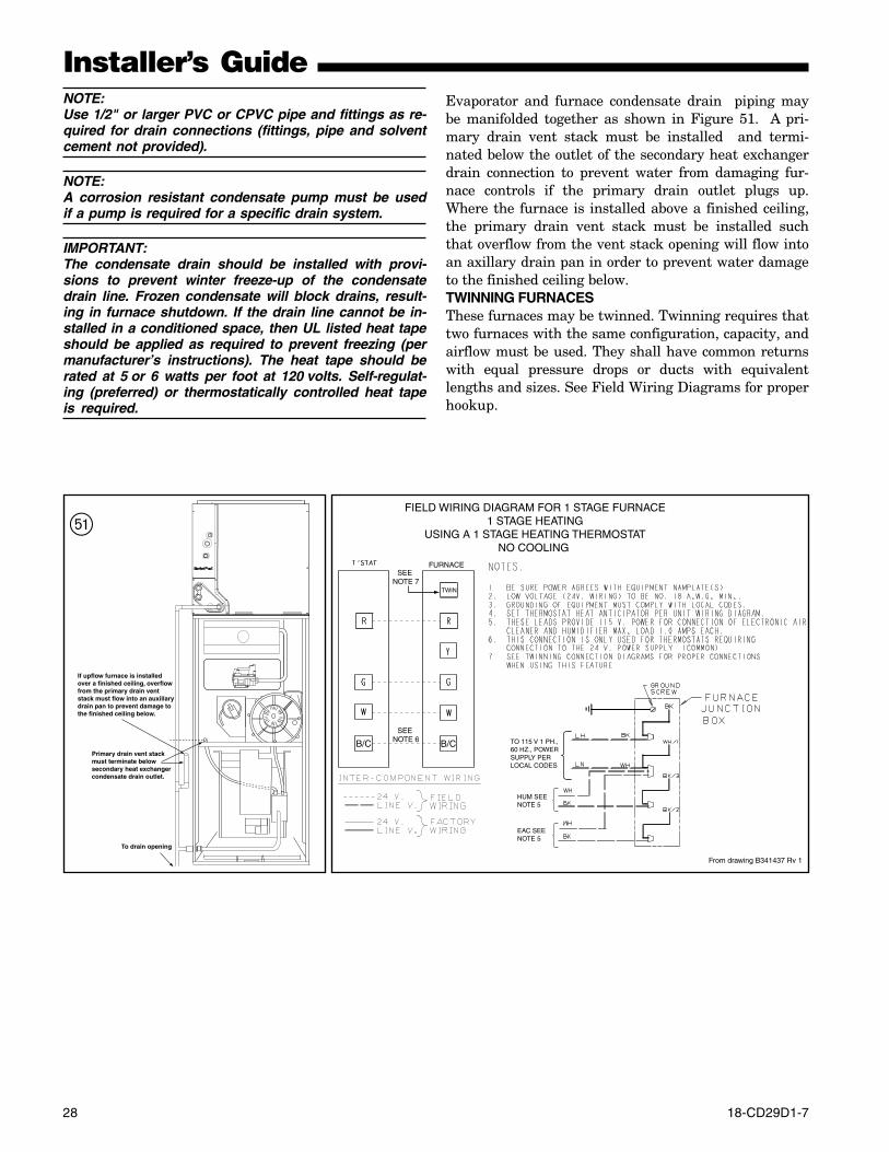
SEE NOTE 6
From drawing B341437 Rv 1
FURNACE
TWIN
SEE NOTE 7
B/CB/C TO 115 V 1 PH.,60 HZ., POWERSUPPLY PERLOCAL CODES
HUM SEENOTE 5
EAC SEENOTE 5
FIELD WIRING DIAGRAM FOR 1 STAGE FURNACE1 STAGE HEATING
USING A 1 STAGE HEATING THERMOSTATNO COOLING
Primary drain vent stackmust terminate belowsecondary heat exchangercondensate drain outlet.
To drain opening
If upflow furnace is installedover a finished ceiling, overflowfrom the primary drain ventstack must flow into an auxillarydrain pan to prevent damage tothe finished ceiling below.
Q
Evaporator and furnace condensate drain piping maybe manifolded together as shown in Figure 51. A pri-mary drain vent stack must be installed and termi-nated below the outlet of the secondary heat exchangerdrain connection to prevent water from damaging fur-nace controls if the primary drain outlet plugs up.Where the furnace is installed above a finished ceiling,the primary drain vent stack must be installed suchthat overflow from the vent stack opening will flow intoan axillary drain pan in order to prevent water damageto the finished ceiling below.TWINNING FURNACESThese furnaces may be twinned. Twinning requires thattwo furnaces with the same configuration, capacity, andairflow must be used. They shall have common returnswith equal pressure drops or ducts with equivalentlengths and sizes. See Field Wiring Diagrams for properhookup.
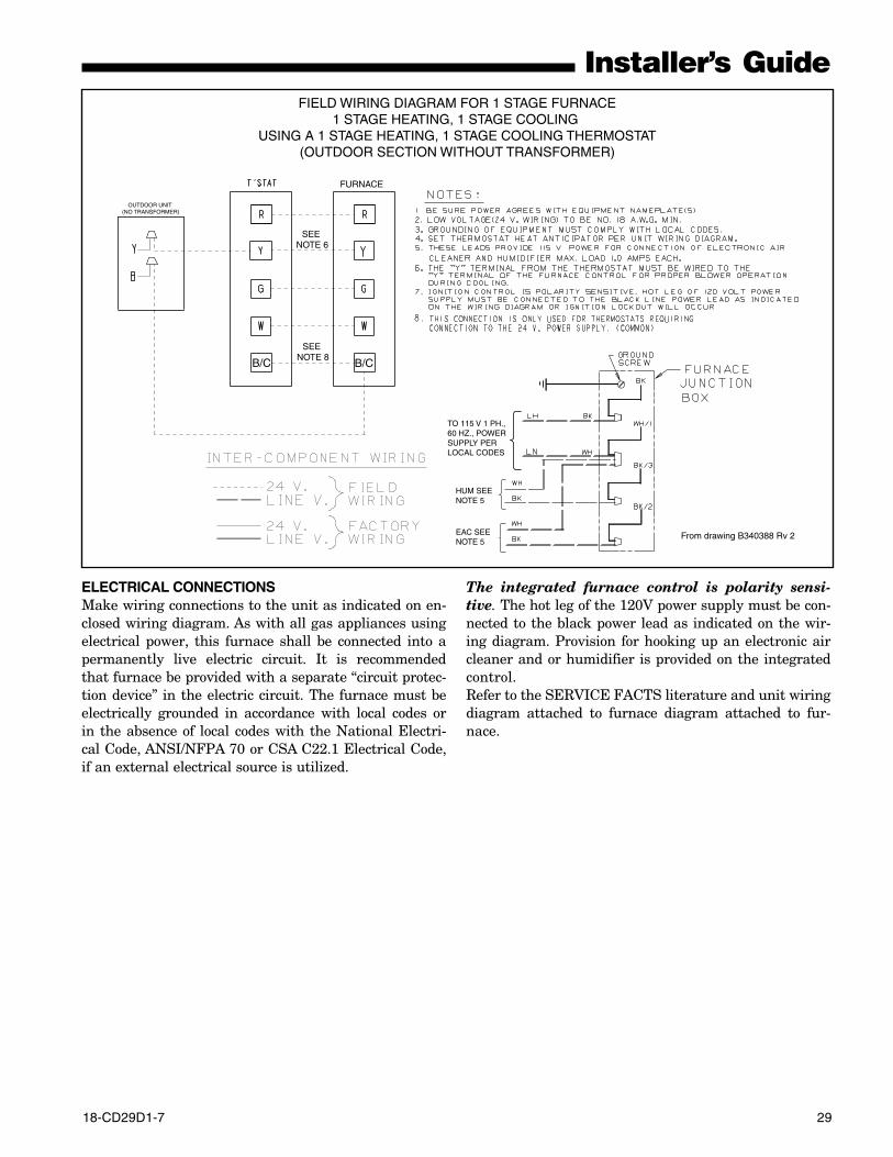
18-CD29D1-7 29
Installer’s Guide
ELECTRICAL CONNECTIONSMake wiring connections to the unit as indicated on en-closed wiring diagram. As with all gas appliances usingelectrical power, this furnace shall be connected into apermanently live electric circuit. It is recommendedthat furnace be provided with a separate “circuit protec-tion device” in the electric circuit. The furnace must beelectrically grounded in accordance with local codes orin the absence of local codes with the National Electri-cal Code, ANSI/NFPA 70 or CSA C22.1 Electrical Code,if an external electrical source is utilized.
OUTDOOR UNIT (NO TRANSFORMER)
SEE NOTE 6
From drawing B340388 Rv 2
SEE NOTE 8
FURNACE
B/CB/C
TO 115 V 1 PH.,60 HZ., POWERSUPPLY PERLOCAL CODES
HUM SEENOTE 5
EAC SEENOTE 5
FIELD WIRING DIAGRAM FOR 1 STAGE FURNACE1 STAGE HEATING, 1 STAGE COOLING
USING A 1 STAGE HEATING, 1 STAGE COOLING THERMOSTAT(OUTDOOR SECTION WITHOUT TRANSFORMER)
The integrated furnace control is polarity sensi-tive. The hot leg of the 120V power supply must be con-nected to the black power lead as indicated on the wir-ing diagram. Provision for hooking up an electronic aircleaner and or humidifier is provided on the integratedcontrol.Refer to the SERVICE FACTS literature and unit wiringdiagram attached to furnace diagram attached to fur-nace.
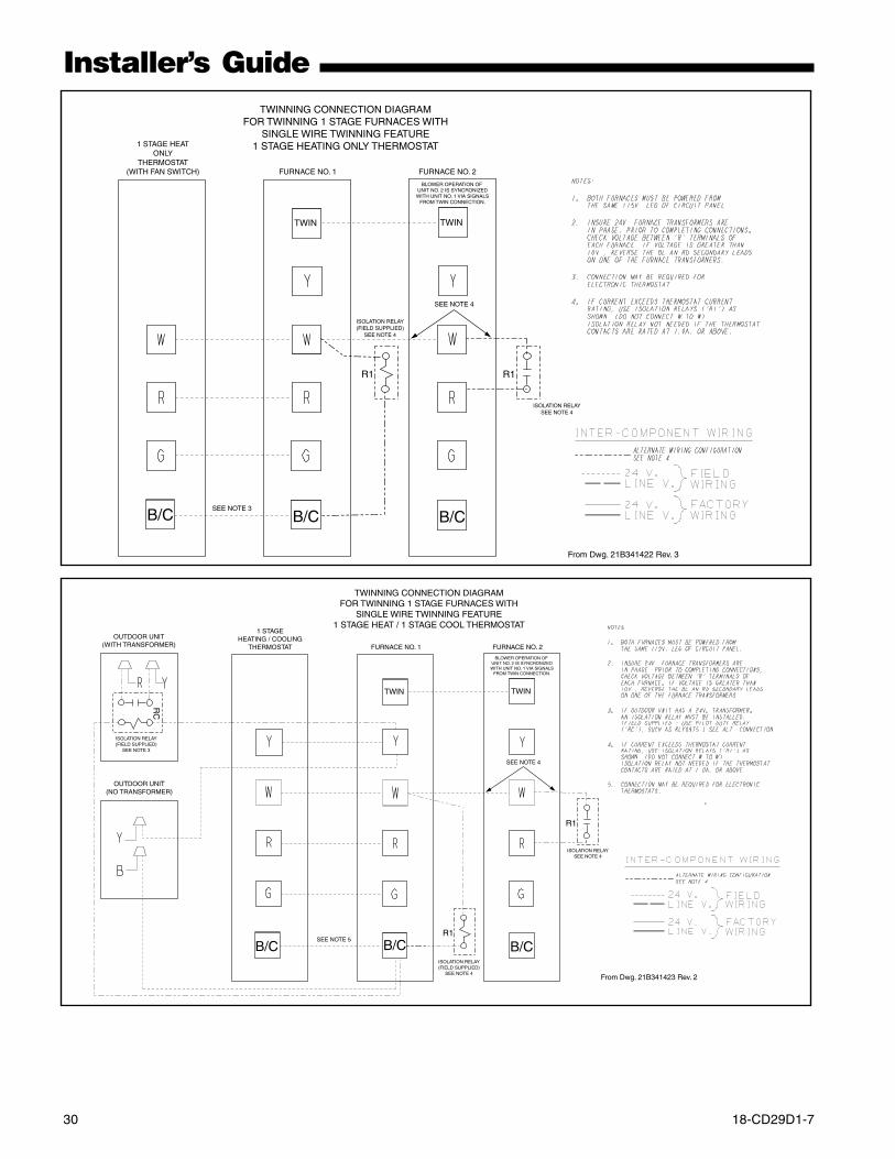
30 18-CD29D1-7
Installer’s Guide
TWIN TWIN
R1 R1
TWINNING CONNECTION DIAGRAMFOR TWINNING 1 STAGE FURNACES WITH
SINGLE WIRE TWINNING FEATURE1 STAGE HEATING ONLY THERMOSTAT1 STAGE HEAT
ONLYTHERMOSTAT
(WITH FAN SWITCH) FURNACE NO. 1 FURNACE NO. 2
BLOWER OPERATION OF UNIT NO. 2 IS SYNCRONIZEDWITH UNIT NO. 1 VIA SIGNALS
FROM TWIN CONNECTION.
SEE NOTE 4
SEE NOTE 3
ISOLATION RELAY(FIELD SUPPLIED)
SEE NOTE 4
ISOLATION RELAYSEE NOTE 4
B/CB/CB/C
From Dwg. 21B341422 Rev. 3
TWIN TWIN
R1
R1
TWINNING CONNECTION DIAGRAMFOR TWINNING 1 STAGE FURNACES WITH
SINGLE WIRE TWINNING FEATURE1 STAGE HEAT / 1 STAGE COOL THERMOSTAT
1 STAGEHEATING / COOLING
THERMOSTAT FURNACE NO. 1 FURNACE NO. 2
BLOWER OPERATION OF UNIT NO. 2 IS SYNCRONIZEDWITH UNIT NO. 1 VIA SIGNALS
FROM TWIN CONNECTION.
SEE NOTE 4
SEE NOTE 5
ISOLATION RELAY(FIELD SUPPLIED)
SEE NOTE 4
ISOLATION RELAYSEE NOTE 4
OUTDOOR UNIT(NO TRANSFORMER)
OUTDOOR UNIT(WITH TRANSFORMER)
RC
ISOLATION RELAY(FIELD SUPPLIED)
SEE NOTE 3
B/CB/CB/C
From Dwg. 21B341423 Rev. 2
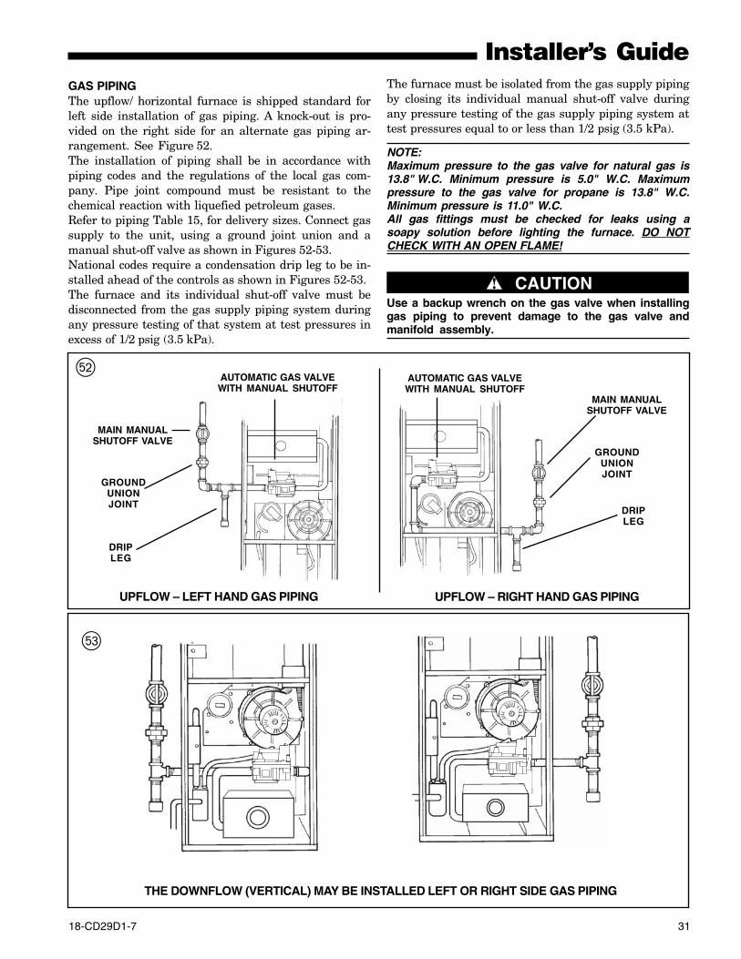
18-CD29D1-7 31
Installer’s GuideThe furnace must be isolated from the gas supply pipingby closing its individual manual shut-off valve duringany pressure testing of the gas supply piping system attest pressures equal to or less than 1/2 psig (3.5 kPa).
NOTE:Maximum pressure to the gas valve for natural gas is13.8" W.C. Minimum pressure is 5.0" W.C. Maximumpressure to the gas valve for propane is 13.8" W.C.Minimum pressure is 11.0" W.C.All gas fittings must be checked for leaks using asoapy solution before lighting the furnace. DO NOTCHECK WITH AN OPEN FLAME!
▲ CAUTION!Use a backup wrench on the gas valve when installinggas piping to prevent damage to the gas valve andmanifold assembly.
UPFLOW – LEFT HAND GAS PIPING UPFLOW – RIGHT HAND GAS PIPING
W AUTOMATIC GAS VALVEWITH MANUAL SHUTOFF
MAIN MANUALSHUTOFF VALVE
GROUNDUNIONJOINT
DRIPLEG
AUTOMATIC GAS VALVEWITH MANUAL SHUTOFF
MAIN MANUALSHUTOFF VALVE
GROUNDUNIONJOINT
DRIPLEG
GAS PIPINGThe upflow/ horizontal furnace is shipped standard forleft side installation of gas piping. A knock-out is pro-vided on the right side for an alternate gas piping ar-rangement. See Figure 52.The installation of piping shall be in accordance withpiping codes and the regulations of the local gas com-pany. Pipe joint compound must be resistant to thechemical reaction with liquefied petroleum gases.Refer to piping Table 15, for delivery sizes. Connect gassupply to the unit, using a ground joint union and amanual shut-off valve as shown in Figures 52-53.National codes require a condensation drip leg to be in-stalled ahead of the controls as shown in Figures 52-53.The furnace and its individual shut-off valve must bedisconnected from the gas supply piping system duringany pressure testing of that system at test pressures inexcess of 1/2 psig (3.5 kPa).
THE DOWNFLOW (VERTICAL) MAY BE INSTALLED LEFT OR RIGHT SIDE GAS PIPING
E
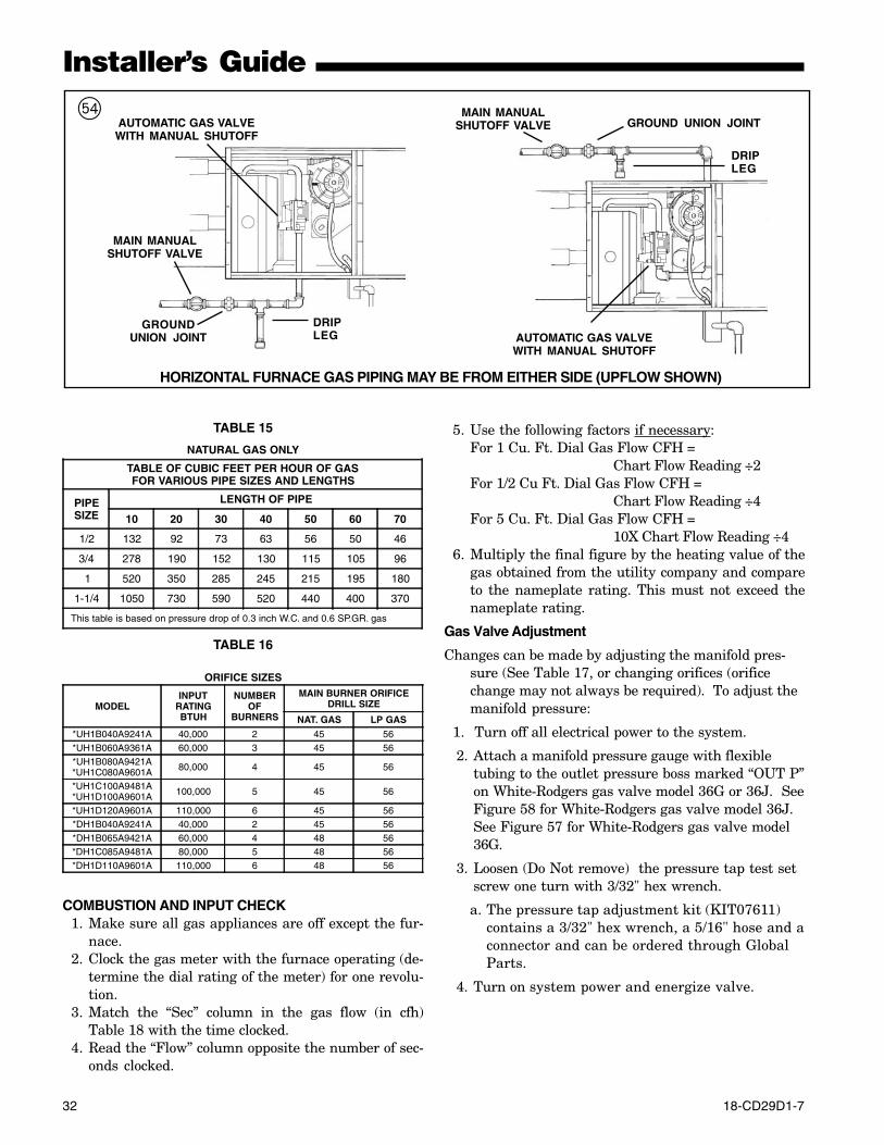
32 18-CD29D1-7
Installer’s Guide
TABLE 15
NATURAL GAS ONLY
TABLE OF CUBIC FEET PER HOUR OF GASFOR VARIOUS PIPE SIZES AND LENGTHS
PIPESIZE
LENGTH OF PIPE
10 20 30 40 50 60 70
1/2 132 92 73 63 56 50 46
3/4 278 190 152 130 115 105 96
1 520 350 285 245 215 195 180
1-1/4 1050 730 590 520 440 400 370
This table is based on pressure drop of 0.3 inch W.C. and 0.6 SP.GR. gas
TABLE 16
ORIFICE SIZES
MODELINPUT
RATINGBTUH
NUMBEROF
BURNERS
MAIN BURNER ORIFICEDRILL SIZE
NAT. GAS LP GAS
*UH1B040A9241A 40,000 2 45 56*UH1B060A9361A 60,000 3 45 56*UH1B080A9421A*UH1C080A9601A 80,000 4 45 56
*UH1C100A9481A*UH1D100A9601A 100,000 5 45 56
*UH1D120A9601A 110,000 6 45 56*DH1B040A9241A 40,000 2 45 56*DH1B065A9421A 60,000 4 48 56*DH1C085A9481A 80,000 5 48 56*DH1D110A9601A 110,000 6 48 56
COMBUSTION AND INPUT CHECK1. Make sure all gas appliances are off except the fur-
nace.2. Clock the gas meter with the furnace operating (de-
termine the dial rating of the meter) for one revolu-tion.
3. Match the “Sec” column in the gas flow (in cfh)Table 18 with the time clocked.
4. Read the “Flow” column opposite the number of sec-onds clocked.
5. Use the following factors if necessary:For 1 Cu. Ft. Dial Gas Flow CFH =
Chart Flow Reading ÷2For 1/2 Cu Ft. Dial Gas Flow CFH =
Chart Flow Reading ÷4For 5 Cu. Ft. Dial Gas Flow CFH =
10X Chart Flow Reading ÷46. Multiply the final figure by the heating value of the
gas obtained from the utility company and compareto the nameplate rating. This must not exceed thenameplate rating.
Gas Valve Adjustment
Changes can be made by adjusting the manifold pres-sure (See Table 17, or changing orifices (orificechange may not always be required). To adjust themanifold pressure:
1. Turn off all electrical power to the system.
2. Attach a manifold pressure gauge with flexibletubing to the outlet pressure boss marked “OUT P”on White-Rodgers gas valve model 36G or 36J. SeeFigure 58 for White-Rodgers gas valve model 36J.See Figure 57 for White-Rodgers gas valve model36G.
3. Loosen (Do Not remove) the pressure tap test setscrew one turn with 3/32" hex wrench.
a. The pressure tap adjustment kit (KIT07611)contains a 3/32" hex wrench, a 5/16" hose and aconnector and can be ordered through GlobalParts.
4. Turn on system power and energize valve.
HORIZONTAL FURNACE GAS PIPING MAY BE FROM EITHER SIDE (UPFLOW SHOWN)
GROUND UNION JOINT
DRIPLEG
AUTOMATIC GAS VALVEWITH MANUAL SHUTOFF
MAIN MANUALSHUTOFF VALVE
GROUNDUNION JOINT
DRIPLEG
MAIN MANUALSHUTOFF VALVE
AUTOMATIC GAS VALVEWITH MANUAL SHUTOFF
R
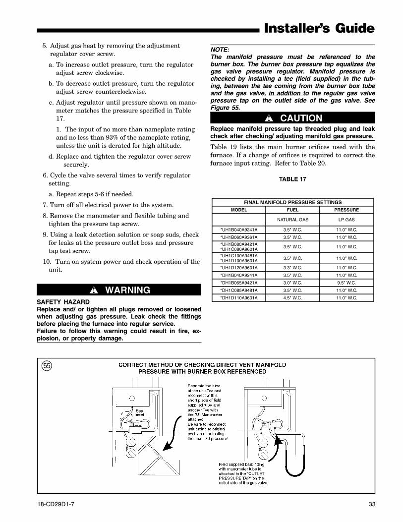
18-CD29D1-7 33
Installer’s GuideNOTE:The manifold pressure must be referenced to theburner box. The burner box pressure tap equalizes thegas valve pressure regulator. Manifold pressure ischecked by installing a tee (field supplied) in the tub-ing, between the tee coming from the burner box tubeand the gas valve, in addition to the regular gas valvepressure tap on the outlet side of the gas valve. SeeFigure 55.
▲ CAUTION!Replace manifold pressure tap threaded plug and leakcheck after checking/ adjusting manifold gas pressure.
Table 19 lists the main burner orifices used with thefurnace. If a change of orifices is required to correct thefurnace input rating. Refer to Table 20.
TABLE 17
FINAL MANIFOLD PRESSURE SETTINGSMODEL FUEL PRESSURE
NATURAL GAS LP GAS
*UH1B040A9241A 3.5" W.C. 11.0" W.C.
*UH1B060A9361A 3.5" W.C. 11.0" W.C.
*UH1B080A9421A*UH1C080A9601A 3.5" W.C. 11.0" W.C.
*UH1C100A9481A*UH1D100A9601A 3.5" W.C. 11.0" W.C.
*UH1D120A9601A 3.3" W.C. 11.0" W.C.
*DH1B040A9241A 3.5" W.C. 11.0" W.C.
*DH1B065A9421A 3.0" W.C. 9.5" W.C.
*DH1C085A9481A 3.5" W.C. 11.0" W.C.
*DH1D110A9601A 4.5" W.C. 11.0" W.C.
5. Adjust gas heat by removing the adjustmentregulator cover screw.
a. To increase outlet pressure, turn the regulatoradjust screw clockwise.
b. To decrease outlet pressure, turn the regulatoradjust screw counterclockwise.
c. Adjust regulator until pressure shown on mano-meter matches the pressure specified in Table17.
1. The input of no more than nameplate ratingand no less than 93% of the nameplate rating,unless the unit is derated for high altitude.
d. Replace and tighten the regulator cover screwsecurely.
6. Cycle the valve several times to verify regulatorsetting.
a. Repeat steps 5-6 if needed.
7. Turn off all electrical power to the system.
8. Remove the manometer and flexible tubing andtighten the pressure tap screw.
9. Using a leak detection solution or soap suds, checkfor leaks at the pressure outlet boss and pressuretap test screw.
10. Turn on system power and check operation of theunit.
unit. ▲ WARNING!SAFETY HAZARDReplace and/ or tighten all plugs removed or loosenedwhen adjusting gas pressure. Leak check the fittingsbefore placing the furnace into regular service.Failure to follow this warning could result in fire, ex-plosion, or property damage.
T
34 18-CD29D1-7
Installer’s GuideHIGH ALTITUDE DERATEInput ratings (BTUH) of these furnaces are based onsea level operation and should not be changed at eleva-tions up to 2,000 ft.If the installation is 2,000 ft. or above, the furnace inputrate (BTUH) shall be reduced 4% for each 1,000 ft.above sea level. The furnace input rate shall be checkedby clocking the gas flow rate (CFH) and multiplying bythe heating value obtained from the local utility sup-plier for the gas being delivered at the installed altitude.Input rate changes can be made by adjusting the mani-fold pressure (min 3.0 - max 3.7 in. W.C. - Natural Gasfor upflow models and min 3.0 - max 4.5 in. W.C. - Natu-ral Gas for downflow models) or changing orifices (ori-fice change may not always be required). If the desiredinput rate can not be achieved with a change in mani-fold pressure, then the orifices must be changed. LP in-stallations will require an orifice change.Installation of this furnace at altitudes above 2,000 ft.(610m) shall be in accordance with the local codes, or inthe absence of local codes, the National Fuel Gas Code,ANSI Z223.1/ NFPA 54 or National Standard ofCanada, Natural Gas and Propane Installation Code,CSA 149.1. Installation of this furnace at altitudesabove 2,000 ft. (610m) shall be made in accordance withthe listed high Altitude Conversion Kit available withthis furnace.
IMPORTANT:Re-install the propane orifices to the same depth as theorifices supplied with the equipment.
GAS FLOW IN CUBIC FEET PER HOUR2 CUBIC FOOT DIAL
SEC. FLOW SEC. FLOW SEC. FLOW SEC. FLOW8 900 29 248 50 144 82 889 800 30 240 51 141 84 8610 720 31 232 52 138 86 8411 655 32 225 53 136 88 8212 600 33 218 54 133 90 8013 555 34 212 55 131 92 7814 514 35 206 56 129 94 7615 480 36 200 57 126 96 7516 450 37 195 58 124 98 7317 424 38 189 59 122 100 7218 400 39 185 60 120 104 6919 379 40 180 62 116 108 6720 360 41 176 64 112 112 6421 343 42 172 66 109 116 6222 327 43 167 68 106 120 6023 313 44 164 70 103 124 5824 300 45 160 72 100 128 5625 288 46 157 74 97 132 5426 277 47 153 76 95 136 5327 267 48 150 78 92 140 5128 257 49 147 80 90 144 50
TABLE 18
Y
ROTATE THE FRONTCOVER INWARDMAKING SURE THATALL SIDE FLANGESARE OUTSIDE OF THEBOX.
INSERT THE TOPFLANGE OF THE FRONTCOVER UNDER THE LIPINSIDE THE BOX
ALL SIDE FLANGESMUST BE OUTSIDE OFTHE BOX
ROTATE THE FRONTCOVER AS SHOWN
18-CD29D1-7 35
Installer’s Guide
LIGHTING INSTRUCTIONS
▲ WARNING!SAFETY HAZARDDO NOT attempt to manually light the burner.Failure to follow this warning could result in propertydamage, personal injury or death.
Lighting instructions appear on each unit. Each instal-lation must be checked out at the time of initial start upto insure proper operation of all components. Check outshould include putting the unit through one completecycle as outlined below.Turn on the main electrical supply and set the thermo-stat above the indicated temperature. The ignitor willautomatically heat, then the gas valve is energized topermit the flow of gas to the burners. After ignition andflame is established, the flame control module monitorsthe flame and supplies power to the gas valve until thethermostat is satisfied.
See Table 19 & 20 for help in selecting orifices if orificechange is required. Furnace input rate and tempera-ture rise should be checked again after changing ori-fices to confirm the proper rate for the altitude.Installations above 4,000 feet may require a pressureswitch change. If required, use the BAYHALT*** Kit(High Altitude Accessory Kit) listed in PRODUCT DATA.
TABLE 19PART NUMBERS FOR REPLACEMENT ORIFICESDRILLSIZE
PARTNUMBER
DRILLSIZE
PARTNUMBER
44454647484950
ORF00501ORF00644ORF00909ORF00910ORF01099ORF00503ORF00493
545556575859
ORF00555ORF00693ORF00907ORF00908ORF01338ORF01339
REINSTALLATION OF THE BURNER BOX COVERFigure 56 shows the correct way to reinstall the burnerbox cover if adjustment or replacement of the flamesensor, hot surface igniter, or main burner orifices haverequired removal of the cover.
TABLE 20
OrificeTwist Drill
Size IfInstalledAt SeaLevel
ALTITUDE ABOVE SEA LEVEL
and Orifice Required At Other Elevations
2000 3000 4000 5000 6000 7000 8000 9000 1000042434445464748
42444546474849
43444547474849
43444547474949
43454647484950
44454748484950
44464748495050
45474849495051
46474849505151
47485050515252
5455565758
5455565859
5555565960
5555575960
5556576061
5556576062
5556586162
5656596263
5656596363
5657606364
From National Fuel Gas Code - Table F-4
▲ WARNING!CARBON MONOXIDE POISONING HAZARDFailure to follow the installation instructions for theventing system being placed into operation could re-sult in carbon monoxide poisoning or death.
START UP AND ADJUSTMENTPRELIMINARY INSPECTIONSWith gas and electrical power “OFF”
1. Duct connections are properly sealed2. Filters are in place3. Venting is properly assembled4. Blower door is in place
Flip the switch on main gas valve within the unit to the“OFF” position. Turn the external gas valve to “ON”.Purge the air from the gas lines. After purging, Checkall gas connections for leaks with a soapy solution —
DO NOT CHECK WITH AN OPEN FLAME. Allow 5minutes for any gas that might have escaped to dissi-pate. LP Gas being heavier than air may require forcedventilation. Flip the switch on the gas valve in the unitto the “ON” position.
I
White-Rodgers 36G gas valve
White-Rodgers 36J gas valve
Outlet Pressure BossRegulatorAdjustment
Inlet PressureBoss (opt.)
On/Off Switch
Outlet Pressure BossOutlet Pressure Boss
On/Offff SwiSwitchch
Inlet Pressurelet PressureBoss Boss (opt.).)
RegululatortorAdjAdjustust
U
36 18-CD29D1-7
Installer’s GuideWhen the furnace reaches the maximum outlet tem-perature as shown on the rating plate, the burnersmust shut off. If they do not shut off after a reasonabletime and overheating is evident, a faulty limit switch isprobable and the limit switch must be replaced. Afterchecking the operation of the limit control, be sure toremove the paper or cardboard from the return air in-let. Refer to Service Facts for additional instructions.NOTE TO INSTALLERReview the following warnings with the owner. Reviewcontents of USER’S INFORMATION MANUAL with theowner.AIRFLOW ADJUSTMENTCheck inlet and outlet air temperatures to make surethey are within the ranges specified on the furnace rat-ing nameplate. If the airflow needs to be increased ordecreased, see the wiring diagram for information onchanging the speed of the blower motor.
▲ WARNING!ELECTRICAL SHOCK HAZARDDisconnect power to the unit before removing theblower door.Failure to follow this warning could result in propertydamage, personal injury or death.
This unit is equipped with a blower door switch whichcuts power to the blower and gas valve causing shut-down when the door is removed. Operation with thedoor removed or ajar can permit the escape of danger-ous fumes. All panels must be securely closed at alltimes for safe operation of the furnace.INDOOR BLOWER TIMINGHeating: The integrated furnace control module con-trols the indoor blower. The blower start is fixed at 45seconds after ignition (10 seconds for downflow models).The FAN-OFF period is field selectable by dip switchesat 60, 100, 140, or 180 seconds. The factory setting is100 seconds (See wiring diagram).Cooling: The fan delay off period is factory set at 0 sec-onds. The option for 80 second delay off is field select-able (See wiring diagram).ROOM AIR THERMOSTATHEAT ANTICIPATOR ADJUSTMENTSet the thermostat heat anticipator according to thecurrent flow measured, or the settings found in thenotes on the furnace wiring diagram (found in the SER-VICE FACTS or inside the furnace casing).
To shut off.For complete shut-down: Flip the switch on the maingas valve to the “OFF” position, (See Figure 57 & 58).Disconnect the electrical supply to the unit.
▲ CAUTION!If this is done during the cold weather months, provi-sions must be taken to prevent freeze-up of all waterpipes and water receptacles.Failure to follow this warning could result in propertydamage.
Whenever your house is to be vacant, arrange tohave someone inspect your house for proper tem-perature. This is very important during freezingweather. If for any reason your furnace shouldfail to operate damage could result, such as fro-zen water pipes.
SEQUENCE OF OPERATIONThermostat call for heatR and W thermostat contacts close signaling the controlmodule to run its self-check routine. After the controlmodule has verified that the pressure switch contactsare open and the limit switch(es) contacts are closed,the draft blower will be energized.As the induced draft blower comes up to speed, thepressure switch contacts will close and the ignitor warmup period will begin. The ignitor will heat for approxi-mately 20 seconds, then the gas valve is energized topermit gas flow to the burners. The flame sensor con-firms that ignition has been achieved.After the flame sensor confirms within a 4 second trialperiod that ignition has been achieved, the delay to fanON period begins timing. After approximately 45 sec-onds the indoor blower motor will be energized and con-tinue to run during the heating cycle (downflow modelshave a 10 second blower ON delay).When the thermostat is satisfied, R and W thermostatcontacts open, the gas valve will close, the flames willextinguish, and the induced draft blower will be de-en-ergized. The indoor blower motor will continue to runfor the fan off period (Field selectable at 60, 100, 140 or180 seconds), then be de-energized by the control mod-ule.
CONTROL AND SAFETY SWITCH ADJUSTMENTSLIMIT SWITCH CHECK OUTThe limit switch is a safety device designed to close thegas valve should the furnace become overheated. Sinceproper operation of this switch is important to thesafety of the unit, it must be checked out on initialstart up by the installer.To check for proper operation of the limit switches, setthe thermostat to a temperature higher than the indi-cated temperature to bring on the gas valve. Restrictthe airflow by blocking the return air (disconnecting theindoor blower may trip the inducer limit).
18-CD29D1-7 37
Installer’s GuideINSTRUCTIONS TO THE OWNERS
▲ WARNING!
EXPLOSION HAZARDIn the event that electrical, fuel, or mechanical failuresoccur, shut off the gas supply off at the manual gasvalve, located on the supply gas piping coming into thefurnace, before turning off the electrical power to thefurnace. Contact the service agency designated by yourdealer.
BURNER BOX TEMPERATURE LIMIT DEVICEAll models are equipped with a manual reset tempera-ture limit located on the burner box. In case of exces-sive temperature, the limit will open and cause the cir-cuit to open which shuts off all flow of gas.ABNORMAL CONDITIONS
1. EXCESSIVE COMBUSTION PRESSURE (WIND INEXCESS OF 40 M.P.H.) VENT OR FLUE BLOCK-AGEIf pressure against induced draft blower outlet be-comes excessive, the pressure switch will open andshut off the gas valve until acceptable combustionpressure is again available.
2. LOSS OF FLAMEIf loss of flame occurs during a heating cycle, orflame is not present at the sensor, the flame controlmodule will close the gas valve. The flame controlmodule will then recycle the ignition sequence,then if ignition is not achieved, it will shut off thegas valve and lock out the system.
3. POWER FAILUREIf there is a power failure during a heating cycle,the system will restart the ignition sequence auto-matically when power is restored if the thermostatstill calls for heat.
4. GAS SUPPLY FAILUREIf loss of flame occurs during a heating cycle, thesystem integrated control module will recycle theignition sequence, then if ignition is not achieved,the integrated control module will shut off the gasvalve and lock out the system.
5. INDUCED DRAFT BLOWER FAILUREIf pressure is not sensed by the pressure switch, thecontacts will remain open and not allow the gasvalve to open, therefore the unit will not start. Iffailure occurs during a running cycle, the pressureswitch contacts will open and the gas valve willclose to shut the unit down.
6. CONDENSATE DRAIN BLOCKAGEIf the condensate drain is blocked, either by debris,improper draining, or by freezing condensate, thepressure switch will receive a signal warning of theaccumulation of condensate in the heat exchangerassembly. The pressure switch contacts will openand remain open, not allowing unit operation. Theunit will not operate until the condensate drain hasbeen cleared, and the condensate flows freely.
7. RESET AFTER LOCKOUTWhen the integrated control module has shut thesystem down and gone into lockout, the systemmust be manually reset before the unit will restart.To reset, turn the system power off, then on, thenoff and then on again within 30 seconds. This maybe done at the unit’s power source or at the ther-mostat. The system will not reset unless the proce-dure off-on-off-on is completed within 30 seconds.
8. RESET AFTER BURNER BOX LIMIT SHUT-DOWNIf the furnace shuts down, one thing that can bechecked is the burner box temperature limit switch.It is located on the bottom of the burner box. Thevent and combustion air inlet terminations shouldbe checked for blockage. If blockage exists, clearthe problem and then the reset button may be de-pressed. If there is no blockage of the termina-tions, the limit switch must be reset by aqualified servicer.
Carbon monoxide, fire or smoke can cause seriousbodily injury, death, and/or property damage.A variety of potential sources of carbon monoxide can befound in a building or dwelling such as gas-fired clothesdryers, gas cooking stoves, water heaters, furnaces andfireplaces. The U.S. Consumer Product Safety Commis-sion recommends that users of gas-burning appliancesinstall carbon monoxide detectors as well as fire andsmoke detectors per the manufacturers installation in-structions to help alert dwelling occupants of the pres-ence of fire, smoke or unsafe levels of carbon monoxide.These devises should be listed by Underwriters Labo-ratories, Inc. Standards for Single and Multiple StationCarbon Monoxide Alarms, UL 2034 or CSA Interna-tional Standard, Residential Carbon Monoxide AlarmingDevices, CSA 6.19
NOTE:The manufacturer of your furnace does not test any de-tectors and makes no representations regarding anybrand or type of detector.
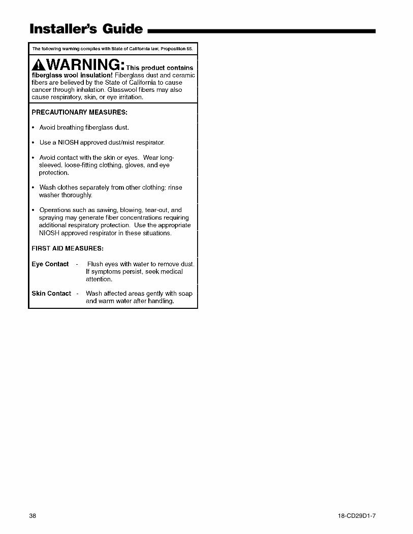
38 18-CD29D1-7
Installer’s Guide
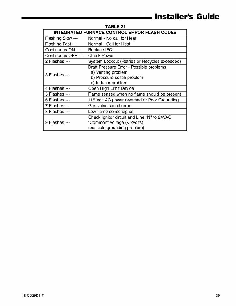
18-CD29D1-7 39
Installer’s GuideTABLE 21
INTEGRATED FURNACE CONTROL ERROR FLASH CODESFlashing Slow --- Normal - No call for HeatFlashing Fast --- Normal - Call for HeatContinuous ON --- Replace IFCContinuous OFF --- Check Power2 Flashes --- System Lockout (Retries or Recycles exceeded)
3 Flashes ---
Draft Pressure Error - Possible problems a) Venting problem b) Pressure seitch problem c) Inducer problem
4 Flashes --- Open High Limit Device5 Flashes --- Flame sensed when no flame should be present6 Flashes --- 115 Volt AC power reversed or Poor Grounding7 Flashes --- Gas valve circuit error8 Flashes --- Low flame sense signal
9 Flashes ---Check Ignitor circuit and Line "N" to 24VAC"Common" voltage (< 2volts)(possible grounding problem)
Since the manufacturer has a policy of continuous product and product data improvement, it reserves theright to change design and specifications without notice.
Trane6200 Troup HighwayTyler, TX 75707
For more information contactyour local dealer (distributor)
Literature Order Number 18-CD29D1-7
File Number 18-CD29D1-7
Supersedes 18-CD29D1-6
Date 12/11