installer’s guide - sensible hvac wholesale
TRANSCRIPT
SSAAFFEETTYY WWAARRNNIINNGGOnly qualified personnel should install and service the equipment. The installation, starting up, and servicing of heating, ventilating, andair-conditioning equipment can be hazardous and requires specific knowledge and training. Improperly installed, adjusted or alteredequipment by an unqualified person could result in death or serious injury. When working on the equipment, observe all precautions in theliterature and on the tags, stickers, and labels that are attached to the equipment.
September 2018 1188--GGJJ8822DD11--11DD--EENN
Variable Speed Air HandlersConvertible 2 — 5 Ton
TAM9A0A24V21DATAM9A0B30V31DATAM9A0C36V31DATAM9A0C42V41DATAM9A0C48V41DATAM9A0C60V51DA
NNoottee:: “Graphics in this document are for representationonly. Actual model may differ in appearance.”
NNoottee:: For use with BAYEA series heaters ONLY
Installer’s Guide
©2016 Ingersoll Rand 18-GJ82D1-1D-EN
SAFETY SECTIONAIR HANDLERSIImmppoorrttaanntt — This document contains a wiringdiagram, a parts list, and service information. This iscustomer property and is to remain with this unit.Please return to service information pack uponcompletion of work.
WWAARRNNIINNGGHHAAZZAARRDDOOUUSS VVOOLLTTAAGGEE!!FFaaiilluurree ttoo ffoollllooww tthhiiss WWaarrnniinngg ccoouulldd rreessuulltt iinnpprrooppeerrttyy ddaammaaggee,, sseevveerree ppeerrssoonnaall iinnjjuurryy,, oorrddeeaatthh..DDiissccoonnnneecctt aallll eelleeccttrriicc ppoowweerr,, iinncclluuddiinngg rreemmootteeddiissccoonnnneeccttss bbeeffoorree sseerrvviicciinngg.. FFoollllooww pprrooppeerrlloocckkoouutt//ttaaggoouutt pprroocceedduurreess ttoo eennssuurree tthhee ppoowweerrccaannnnoott bbee iinnaaddvveerrtteennttllyy eenneerrggiizzeedd..
CCAAUUTTIIOONNGGRROOUUNNDDIINNGG RREEQQUUIIRREEDD!!FFaaiilluurree ttoo iinnssppeecctt oorr uussee pprrooppeerr sseerrvviiccee ttoooollss mmaayyrreessuulltt iinn eeqquuiippmmeenntt ddaammaaggee oorr ppeerrssoonnaall iinnjjuurryy..RReeccoonnnneecctt aallll ggrroouunnddiinngg ddeevviicceess.. AAllll ppaarrttss ooff tthhiisspprroodduucctt tthhaatt aarree ccaappaabbllee ooff ccoonndduuccttiinngg eelleeccttrriiccaallccuurrrreenntt aarree ggrroouunnddeedd.. IIff ggrroouunnddiinngg wwiirreess,, ssccrreewwss,,ssttrraappss,, cclliippss,, nnuuttss,, oorr wwaasshheerrss uusseedd ttoo ccoommpplleettee aappaatthh ttoo ggrroouunndd aarree rreemmoovveedd ffoorr sseerrvviiccee,, tthheeyy mmuussttbbee rreettuurrnneedd ttoo tthheeiirr oorriiggiinnaall ppoossiittiioonn aanndd pprrooppeerrllyyffaasstteenneedd..
WWAARRNNIINNGGLLIIVVEE EELLEECCTTRRIICCAALL CCOOMMPPOONNEENNTTSS!!FFaaiilluurree ttoo ffoollllooww tthhiiss WWaarrnniinngg ccoouulldd rreessuulltt iinnpprrooppeerrttyy ddaammaaggee,, sseevveerree ppeerrssoonnaall iinnjjuurryy,, oorrddeeaatthh..FFoollllooww aallll eelleeccttrriiccaall ssaaffeettyy pprreeccaauuttiioonnss wwhheenneexxppoosseedd ttoo lliivvee eelleeccttrriiccaall ccoommppoonneennttss.. IItt mmaayy bbeenneecceessssaarryy ttoo wwoorrkk wwiitthh lliivvee eelleeccttrriiccaall ccoommppoonneennttssdduurriinngg iinnssttaallllaattiioonn,, tteessttiinngg,, sseerrvviicciinngg,, aannddttrroouubblleesshhoooottiinngg ooff tthhiiss pprroodduucctt..
WWAARRNNIINNGGPPRREESSSSUURRIIZZEEDD RREEFFRRIIGGEERRAANNTT!!FFaaiilluurree ttoo ffoollllooww tthhiiss WWaarrnniinngg ccoouulldd rreessuulltt iinnppeerrssoonnaall iinnjjuurryySSyysstteemm ccoonnttaaiinnss ooiill aanndd rreeffrriiggeerraanntt uunnddeerr hhiigghhpprreessssuurree.. RReeccoovveerr rreeffrriiggeerraanntt ttoo rreelliieevvee pprreessssuurreebbeeffoorree ooppeenniinngg tthhee ssyysstteemm.. DDoo nnoo uussee nnoonn--aapppprroovveedd rreeffrriiggeerraannttss oorr rreeffrriiggeerraanntt ssuubbssttiittuutteess oorrrreeffrriiggeerraanntt aaddddiittiivveess..
CCAAUUTTIIOONNSSHHAARRPP EEDDGGEE HHAAZZAARRDD!!FFaaiilluurree ttoo ffoollllooww tthhiiss CCaauuttiioonn ccoouulldd rreessuulltt iinnpprrooppeerrttyy ddaammaaggee oorr ppeerrssoonnaall iinnjjuurryy..BBee ccaarreeffuull ooff sshhaarrpp eeddggeess oonn eeqquuiippmmeenntt oorr aannyyccuuttss mmaaddee oonn sshheeeett mmeettaall wwhhiillee iinnssttaalllliinngg oorrsseerrvviicciinngg..
WWAARRNNIINNGGWWAARRNNIINNGG!!TThhiiss pprroodduucctt ccaann eexxppoossee yyoouu ttoo cchheemmiiccaallssiinncclluuddiinngg lleeaadd,, wwhhiicchh aarree kknnoowwnn ttoo tthhee SSttaattee ooffCCaalliiffoorrnniiaa ttoo ccaauussee ccaanncceerr aanndd bbiirrtthh ddeeffeeccttss oorrootthheerr rreepprroodduuccttiivvee hhaarrmm.. FFoorr mmoorree iinnffoorrmmaattiioonn ggoottoo wwwwww..PP6655WWaarrnniinnggss..ccaa..ggoovv..
IImmppoorrttaanntt:: Panel damage can occur with prolongedexposure to POE lubricants. Air handlerfront panels that come in contact with POEoil must be washed immediately withsoapy water.
IImmppoorrttaanntt:: The TAM9 air handlers are only compatiblewith BAYEA** internal electric heaters.
NNoottee:: Representative illustrations only included in thisdocument. Most illustrations display the upflowconfiguration.
18-GJ82D1-1D-EN 3
Installer Guide Notes . . . . . . . . . . . . . . . . . . . . . . . 4
Unit Design. . . . . . . . . . . . . . . . . . . . . . . . . . . . . . . . . 5
Unit Install Preparation . . . . . . . . . . . . . . . . . . . . . 7
Optional Accessories . . . . . . . . . . . . . . . . . . . . . . . 8
Optional Cabinet Disassembly. . . . . . . . . . . . . . 9
Placing Unit at Location . . . . . . . . . . . . . . . . . . . 13
Unit Location Considerations . . . . . . . . . . . . . . 14
Four-Way Conversion . . . . . . . . . . . . . . . . . . . . . 15
Ducted and Non-Ducted ReturnApplications . . . . . . . . . . . . . . . . . . . . . . . . . . . . . . . 17
Additional Unit PreparationConsiderations . . . . . . . . . . . . . . . . . . . . . . . . . . . . 18
Setting the Unit — VerticalInstallation . . . . . . . . . . . . . . . . . . . . . . . . . . . . . . . . 19
Setting the Unit — HorizontalInstallations . . . . . . . . . . . . . . . . . . . . . . . . . . . . . . . 21
Connecting the Duct work . . . . . . . . . . . . . . . . . 22
Refrigerant Line . . . . . . . . . . . . . . . . . . . . . . . . . . . 23Refrigerant System Layout . . . . . . . . . . . . . . . 23
Refrigerant Line Brazing . . . . . . . . . . . . . . . . . . . 24
Condensate Drain Piping . . . . . . . . . . . . . . . . . . 28
Electrical — Low Voltage . . . . . . . . . . . . . . . . . . 30
Control Panel Reinstallation . . . . . . . . . . . . . . . 36
Electrical — High Voltage. . . . . . . . . . . . . . . . . . 37
TAM9 OUTLINE DRAWING . . . . . . . . . . . . . . . . 40
Display Assembly / HumanInterface . . . . . . . . . . . . . . . . . . . . . . . . . . . . . . . . . . . 41
TAM9 — Technician Menu andConfiguration tree . . . . . . . . . . . . . . . . . . . . . . . . . 42
Filters. . . . . . . . . . . . . . . . . . . . . . . . . . . . . . . . . . . . . . 47System Charge Adjustments . . . . . . . . . . . . . 47
System Start Up . . . . . . . . . . . . . . . . . . . . . . . . . . . 48
TAM9 Sequence of Operation . . . . . . . . . . . . . 49Abbreviations . . . . . . . . . . . . . . . . . . . . . . . . . . . 49
Fault Reporting . . . . . . . . . . . . . . . . . . . . . . . . . . . . 51
Checkout Procedures . . . . . . . . . . . . . . . . . . . . . . 52
Table of Contents
4 18-GJ82D1-1D-EN
Installer Guide Notes
AALLLL PPhhaasseess ooff tthhiiss iinnssttaallllaattiioonn mmuusstt ccoommppllyy wwiitthhNNAATTIIOONNAALL,, SSTTAATTEE aanndd LLOOCCAALL CCOODDEESS!!
IImmppoorrttaanntt:: This Document is customer property and isto remain with t his unit. Please return toservice information upon completion ofwork
IImmppoorrttaanntt:: These instructions do not cover allvariations in systems nor provide for everypossible contingency to be met inconnection with the installation. Shouldfurther information be desired or shouldparticular problems arise which are notcovered sufficiently for the purchaser’spurposes, the matter should be referred toyour installing dealer.
SSeeee TTAAMM99 SSeerrvviiccee FFaaccttss ddooccuummeenntt ffoorr iinnffoorrmmaattiioonnoonn rreeaaddiinngg tthhee DDiissppllaayy,, AAiirr FFllooww TTaabblleess aannddTTrroouubblleesshhoooottiinngg FFlloowwcchhaarrttss..
IImmppoorrttaanntt:: The low voltage wire harness is shipped inthe supplied document pack.
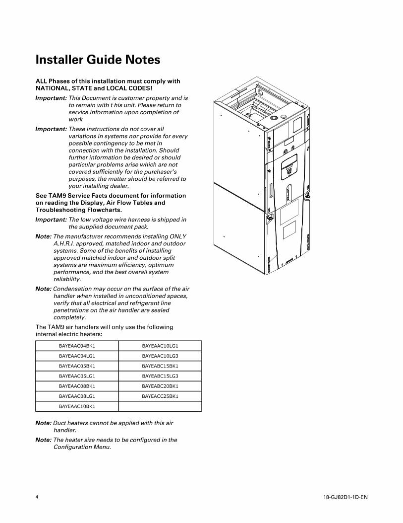
NNoottee:: The manufacturer recommends installing ONLYA.H.R.I. approved, matched indoor and outdoorsystems. Some of the benefits of installingapproved matched indoor and outdoor splitsystems are maximum efficiency, optimumperformance, and the best overall systemreliability.
NNoottee:: Condensation may occur on the surface of the airhandler when installed in unconditioned spaces,verify that all electrical and refrigerant linepenetrations on the air handler are sealedcompletely.
The TAM9 air handlers will only use the followinginternal electric heaters:
BAYEAAC04BK1 BAYEAAC10LG1
BAYEAAC04LG1 BAYEAAC10LG3
BAYEAAC05BK1 BAYEABC15BK1
BAYEAAC05LG1 BAYEABC15LG3
BAYEAAC08BK1 BAYEABC20BK1
BAYEAAC08LG1 BAYEACC25BK1
BAYEAAC10BK1
NNoottee:: Duct heaters cannot be applied with this airhandler.
NNoottee:: The heater size needs to be configured in theConfiguration Menu.
18-GJ82D1-1D-EN 5
Unit Design
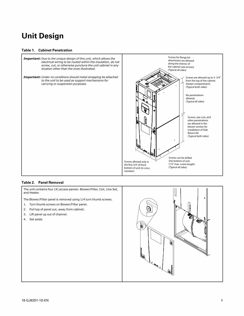
Table 1. Cabinet Penetration
Important: Due to the unique design of this unit, which allows theelectrical wiring to be routed within the insulation, do notscrew, cut, or otherwise puncture the unit cabinet in anylocation other than the ones illustrated.
Important: Under no conditions should metal strapping be attachedto the unit to be used as support mechanisms forcarrying or suspension purposes.
Screws can be drilled into bottom of unit. (1/2” max. screw length)(Typical all sides)
Screws, saw cuts, and other penetrations are allowed in the blower section for installation of Side Return Kit. (Typical both sides)
Screws are allowed up to 3- 3/4” from the top of the cabinet (heater compartment).(Typical both sides)
Screws for �ange kitattachment are allowedalong the interior of the cabinet (see arrows)(Typical all sides)
No penetrations allowed.(Typical all sides)
Screws allowed only in the !rst 3/4” of front bottom of unit (in cross member)
Table 2. Panel Removal
The unit contains four (4) access panels: Blower/Filter, Coil, Line Set,and Heater.
The Blower/Filter panel is removed using 1/4 turn thumb screws.
1. Turn thumb screws on Blower/Filter panel.
2. Pull top of panel out, away from cabinet.
3. Lift panel up out of channel.
4. Set aside.
6 18-GJ82D1-1D-EN
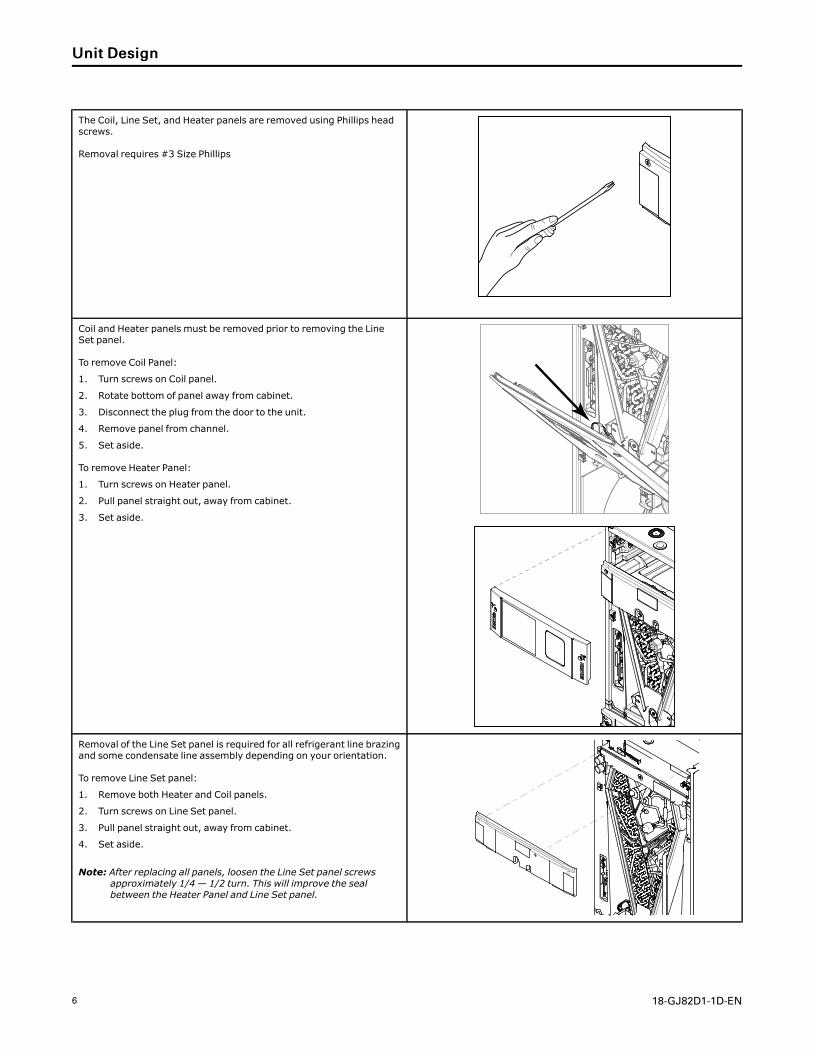
The Coil, Line Set, and Heater panels are removed using Phillips headscrews.
Removal requires #3 Size Phillips
Coil and Heater panels must be removed prior to removing the LineSet panel.
To remove Coil Panel:
1. Turn screws on Coil panel.
2. Rotate bottom of panel away from cabinet.
3. Disconnect the plug from the door to the unit.
4. Remove panel from channel.
5. Set aside.
To remove Heater Panel:
1. Turn screws on Heater panel.
2. Pull panel straight out, away from cabinet.
3. Set aside.
Removal of the Line Set panel is required for all refrigerant line brazingand some condensate line assembly depending on your orientation.
To remove Line Set panel:
1. Remove both Heater and Coil panels.
2. Turn screws on Line Set panel.
3. Pull panel straight out, away from cabinet.
4. Set aside.
Note: After replacing all panels, loosen the Line Set panel screwsapproximately 1/4 — 1/2 turn. This will improve the sealbetween the Heater Panel and Line Set panel.
UUnniitt DDeessiiggnn
18-GJ82D1-1D-EN 7
Unit Install Preparation
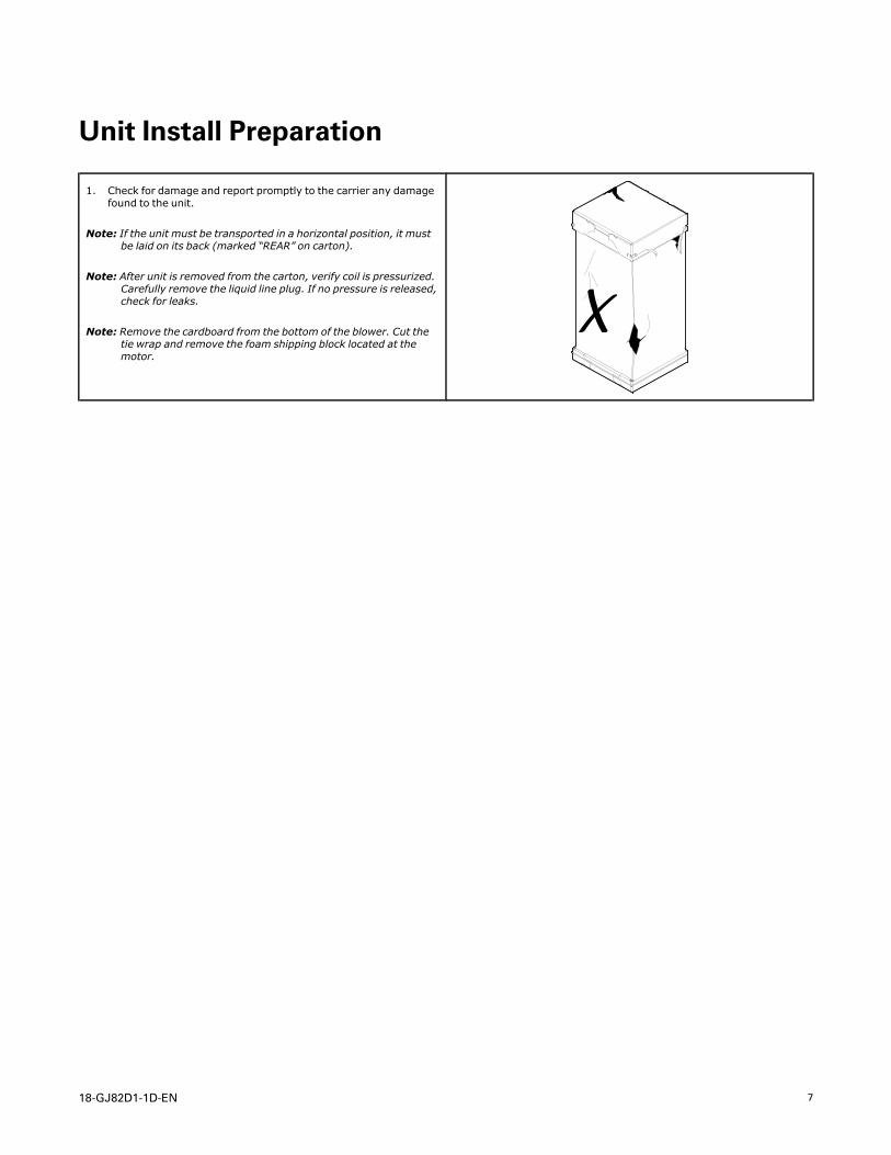
1. Check for damage and report promptly to the carrier any damagefound to the unit.
Note: If the unit must be transported in a horizontal position, it mustbe laid on its back (marked “REAR” on carton).
Note: After unit is removed from the carton, verify coil is pressurized.Carefully remove the liquid line plug. If no pressure is released,check for leaks.
Note: Remove the cardboard from the bottom of the blower. Cut thetie wrap and remove the foam shipping block located at themotor.
8 18-GJ82D1-1D-EN
Optional Accessories
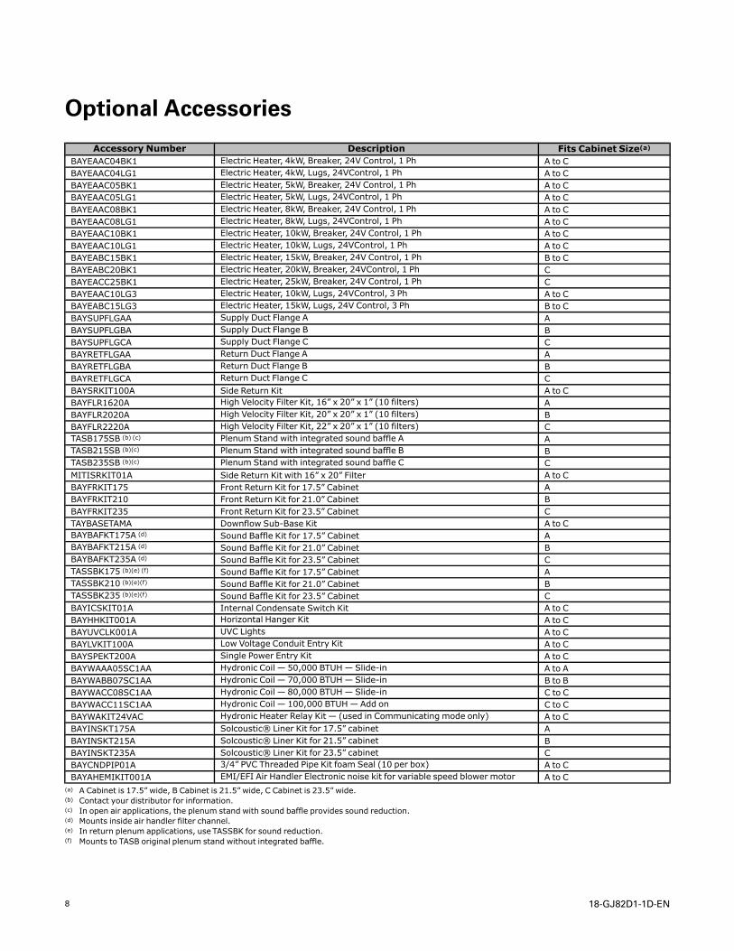
Accessory Number Description Fits Cabinet Size(a)BAYEAAC04BK1 Electric Heater, 4kW, Breaker, 24V Control, 1 Ph A to CBAYEAAC04LG1 Electric Heater, 4kW, Lugs, 24VControl, 1 Ph A to CBAYEAAC05BK1 Electric Heater, 5kW, Breaker, 24V Control, 1 Ph A to CBAYEAAC05LG1 Electric Heater, 5kW, Lugs, 24VControl, 1 Ph A to CBAYEAAC08BK1 Electric Heater, 8kW, Breaker, 24V Control, 1 Ph A to CBAYEAAC08LG1 Electric Heater, 8kW, Lugs, 24VControl, 1 Ph A to CBAYEAAC10BK1 Electric Heater, 10kW, Breaker, 24V Control, 1 Ph A to CBAYEAAC10LG1 Electric Heater, 10kW, Lugs, 24VControl, 1 Ph A to CBAYEABC15BK1 Electric Heater, 15kW, Breaker, 24V Control, 1 Ph B to CBAYEABC20BK1 Electric Heater, 20kW, Breaker, 24VControl, 1 Ph CBAYEACC25BK1 Electric Heater, 25kW, Breaker, 24V Control, 1 Ph CBAYEAAC10LG3 Electric Heater, 10kW, Lugs, 24VControl, 3 Ph A to CBAYEABC15LG3 Electric Heater, 15kW, Lugs, 24V Control, 3 Ph B to CBAYSUPFLGAA Supply Duct Flange A ABAYSUPFLGBA Supply Duct Flange B BBAYSUPFLGCA Supply Duct Flange C CBAYRETFLGAA Return Duct Flange A ABAYRETFLGBA Return Duct Flange B BBAYRETFLGCA Return Duct Flange C CBAYSRKIT100A Side Return Kit A to CBAYFLR1620A High Velocity Filter Kit, 16” x 20” x 1” (10 filters) ABAYFLR2020A High Velocity Filter Kit, 20” x 20” x 1” (10 filters) BBAYFLR2220A High Velocity Filter Kit, 22” x 20” x 1” (10 filters) CTASB175SB (b) (c) Plenum Stand with integrated sound baffle A ATASB215SB (b)(c) Plenum Stand with integrated sound baffle B BTASB235SB (b)(c) Plenum Stand with integrated sound baffle C CMITISRKIT01A Side Return Kit with 16” x 20” Filter A to CBAYFRKIT175 Front Return Kit for 17.5” Cabinet ABAYFRKIT210 Front Return Kit for 21.0” Cabinet BBAYFRKIT235 Front Return Kit for 23.5” Cabinet CTAYBASETAMA Downflow Sub-Base Kit A to CBAYBAFKT175A (d) Sound Baffle Kit for 17.5” Cabinet ABAYBAFKT215A (d) Sound Baffle Kit for 21.0” Cabinet BBAYBAFKT235A (d) Sound Baffle Kit for 23.5” Cabinet CTASSBK175 (b)(e) (f) Sound Baffle Kit for 17.5” Cabinet ATASSBK210 (b)(e)(f) Sound Baffle Kit for 21.0” Cabinet BTASSBK235 (b)(e)(f) Sound Baffle Kit for 23.5” Cabinet CBAYICSKIT01A Internal Condensate Switch Kit A to CBAYHHKIT001A Horizontal Hanger Kit A to CBAYUVCLK001A UVC Lights A to CBAYLVKIT100A Low Voltage Conduit Entry Kit A to CBAYSPEKT200A Single Power Entry Kit A to CBAYWAAA05SC1AA Hydronic Coil — 50,000 BTUH— Slide-in A to ABAYWABB07SC1AA Hydronic Coil — 70,000 BTUH— Slide-in B to BBAYWACC08SC1AA Hydronic Coil — 80,000 BTUH— Slide-in C to CBAYWACC11SC1AA Hydronic Coil — 100,000 BTUH—Add on C to CBAYWAKIT24VAC Hydronic Heater Relay Kit — (used in Communicating mode only) A to CBAYINSKT175A Solcoustic® Liner Kit for 17.5” cabinet ABAYINSKT215A Solcoustic® Liner Kit for 21.5” cabinet BBAYINSKT235A Solcoustic® Liner Kit for 23.5” cabinet CBAYCNDPIP01A 3/4” PVC Threaded Pipe Kit foam Seal (10 per box) A to CBAYAHEMIKIT001A EMI/EFI Air Handler Electronic noise kit for variable speed blower motor A to C
(a) A Cabinet is 17.5” wide, B Cabinet is 21.5” wide, C Cabinet is 23.5” wide.(b) Contact your distributor for information.(c) In open air applications, the plenum stand with sound baffle provides sound reduction.(d) Mounts inside air handler filter channel.(e) In return plenum applications, use TASSBK for sound reduction.(f) Mounts to TASB original plenum stand without integrated baffle.
18-GJ82D1-1D-EN 9
Optional Cabinet Disassembly
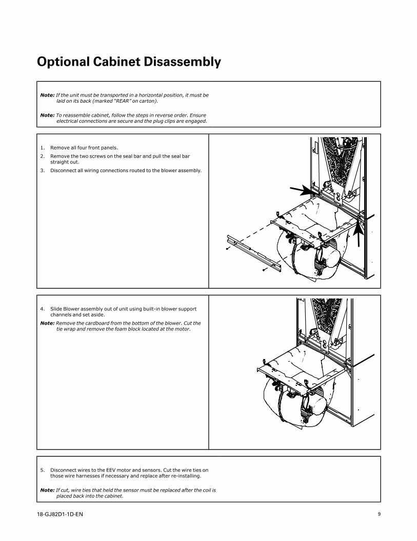
Note: If the unit must be transported in a horizontal position, it must belaid on its back (marked “REAR” on carton).
Note: To reassemble cabinet, follow the steps in reverse order. Ensureelectrical connections are secure and the plug clips are engaged.
1. Remove all four front panels.
2. Remove the two screws on the seal bar and pull the seal barstraight out.
3. Disconnect all wiring connections routed to the blower assembly.
4. Slide Blower assembly out of unit using built-in blower supportchannels and set aside.
Note: Remove the cardboard from the bottom of the blower. Cut thetie wrap and remove the foam block located at the motor.
5. Disconnect wires to the EEV motor and sensors. Cut the wire ties onthose wire harnesses if necessary and replace after re-installing.
Note: If cut, wire ties that held the sensor must be replaced after the coil isplaced back into the cabinet.
10 18-GJ82D1-1D-EN
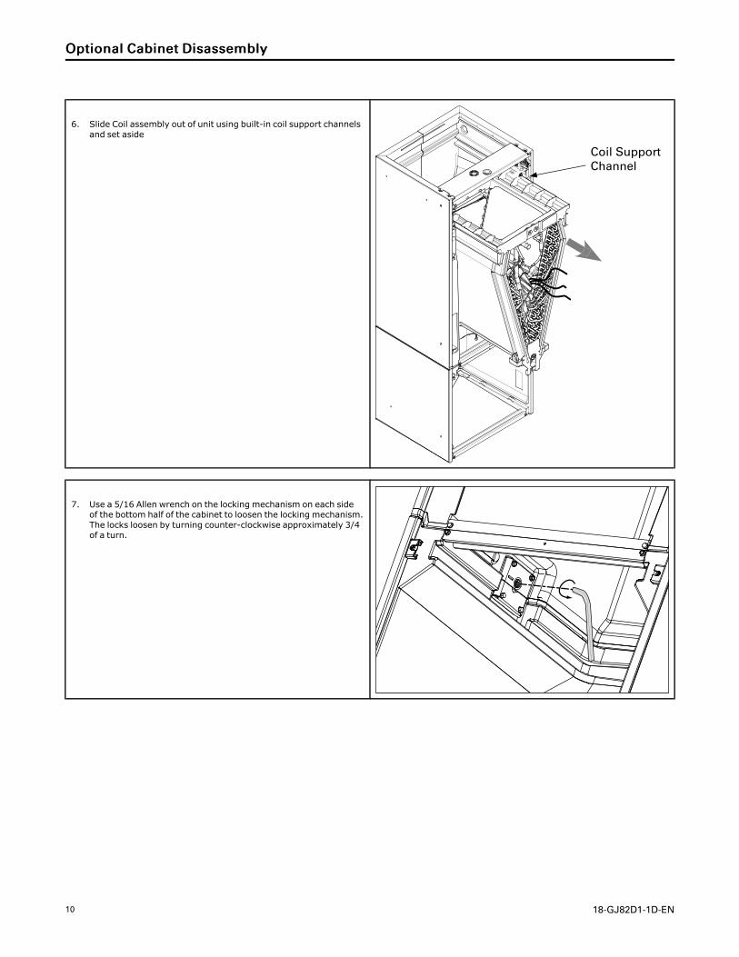
6. Slide Coil assembly out of unit using built-in coil support channelsand set aside
Coil SupportChannel
7. Use a 5/16 Allen wrench on the locking mechanism on each sideof the bottom half of the cabinet to loosen the locking mechanism.The locks loosen by turning counter-clockwise approximately 3/4of a turn.
OOppttiioonnaall CCaabbiinneett DDiissaasssseemmbbllyy
18-GJ82D1-1D-EN 11
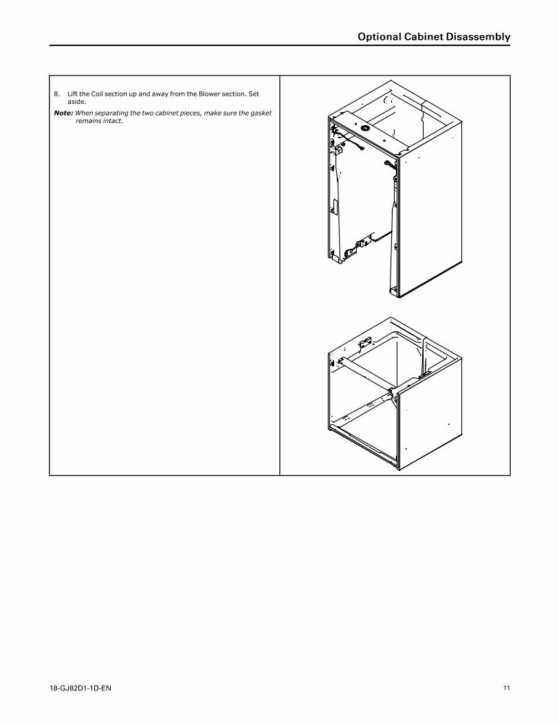
8. Lift the Coil section up and away from the Blower section. Setaside.
Note:When separating the two cabinet pieces, make sure the gasketremains intact.
OOppttiioonnaall CCaabbiinneett DDiissaasssseemmbbllyy
12 18-GJ82D1-1D-EN
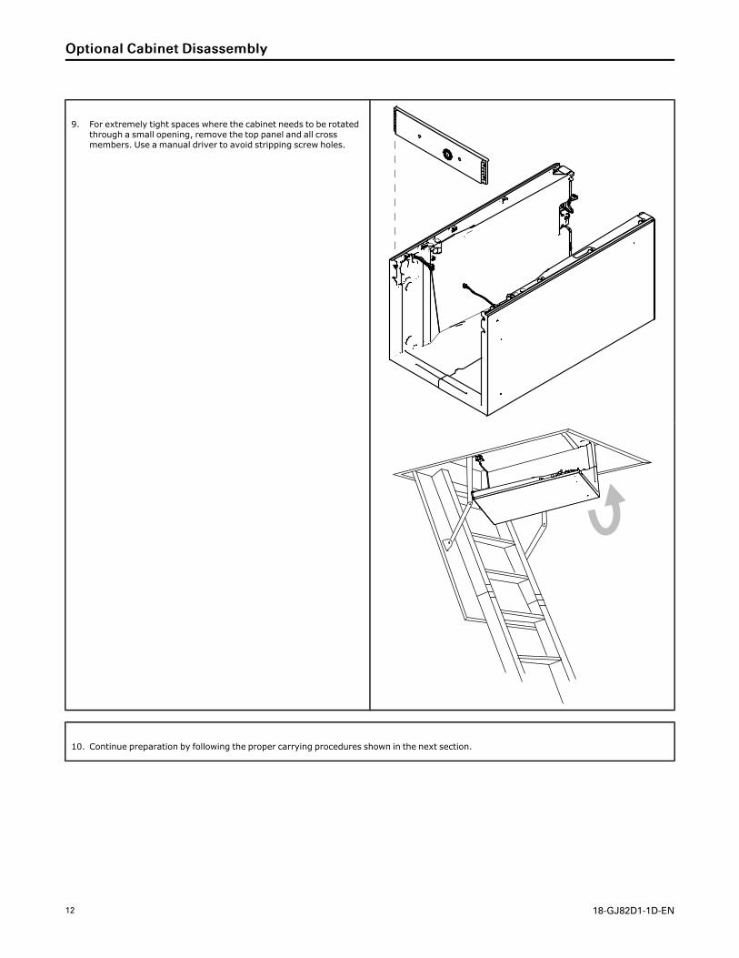
9. For extremely tight spaces where the cabinet needs to be rotatedthrough a small opening, remove the top panel and all crossmembers. Use a manual driver to avoid stripping screw holes.
10. Continue preparation by following the proper carrying procedures shown in the next section.
OOppttiioonnaall CCaabbiinneett DDiissaasssseemmbbllyy
18-GJ82D1-1D-EN 13
Placing Unit at Location
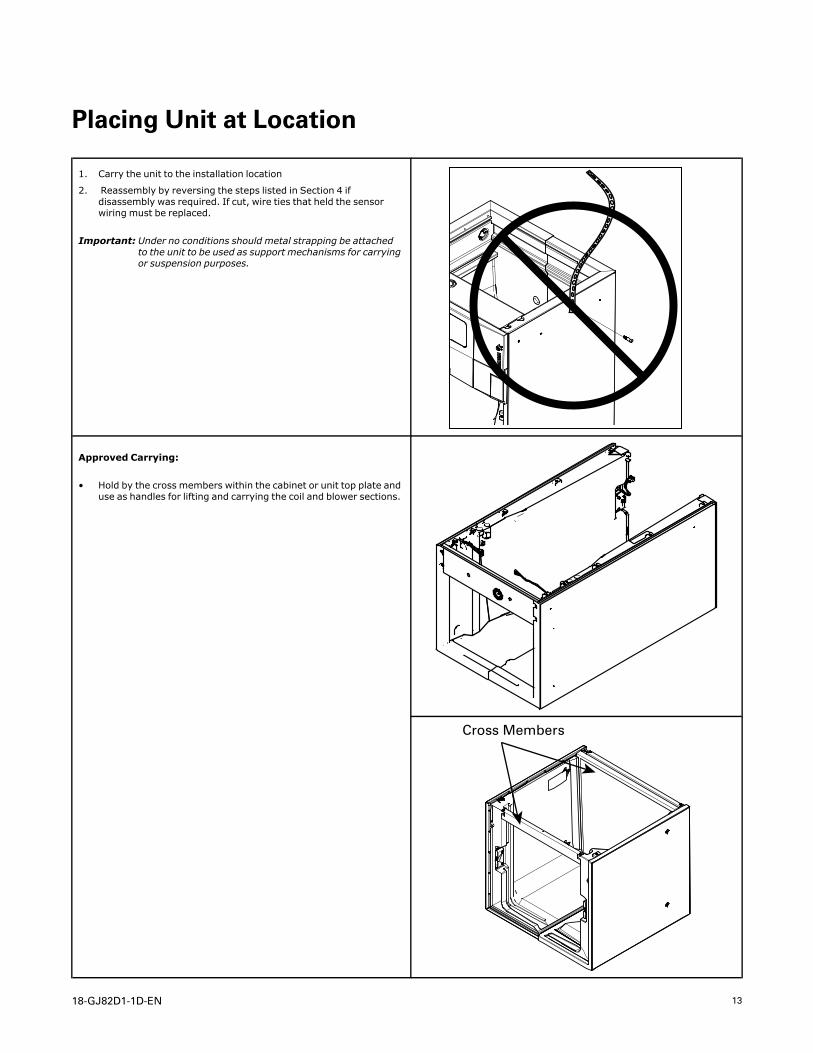
1. Carry the unit to the installation location
2. Reassembly by reversing the steps listed in Section 4 ifdisassembly was required. If cut, wire ties that held the sensorwiring must be replaced.
Important: Under no conditions should metal strapping be attachedto the unit to be used as support mechanisms for carryingor suspension purposes.
Approved Carrying:
• Hold by the cross members within the cabinet or unit top plate anduse as handles for lifting and carrying the coil and blower sections.
Cross Members
14 18-GJ82D1-1D-EN
Unit Location Considerations
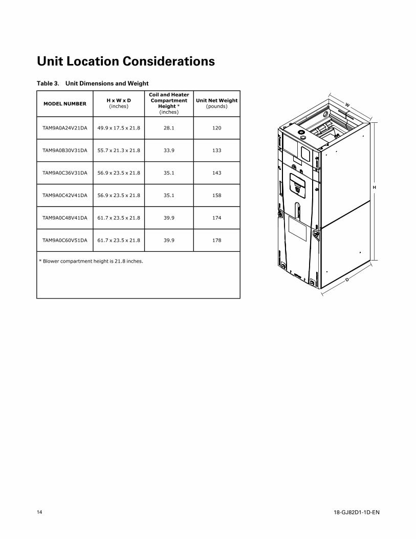
Table 3. Unit Dimensions and Weight
MODEL NUMBERH xW x D(inches)
Coil and HeaterCompartmentHeight *(inches)
Unit NetWeight(pounds)
D
H
W
TAM9A0A24V21DA 49.9 x 17.5 x 21.8 28.1 120
TAM9A0B30V31DA 55.7 x 21.3 x 21.8 33.9 133
TAM9A0C36V31DA 56.9 x 23.5 x 21.8 35.1 143
TAM9A0C42V41DA 56.9 x 23.5 x 21.8 35.1 158
TAM9A0C48V41DA 61.7 x 23.5 x 21.8 39.9 174
TAM9A0C60V51DA 61.7 x 23.5 x 21.8 39.9 178
* Blower compartment height is 21.8 inches.
18-GJ82D1-1D-EN 15
Four-Way Conversion
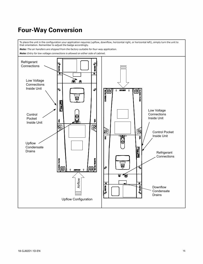
To place the unit in the configuration your application requires (upflow, downflow, horizontal right, or horizontal left), simply turn the unit tothat orientation. Remember to adjust the badge accordingly.
Note: The air handlers are shipped from the factory suitable for four-way application.
Note: Entry for low voltage connections is allowed on either side of cabinet.
Airf
low
Upflow Configuration
Refrigerant Connections
Low Voltage Connections Inside Unit
Control Pocket Inside Unit
Upflow Condensate Drains
Low Voltage Connections Inside Unit
Control Pocket Inside Unit
Refrigerant Connections
Downflow Condensate Drains
16 18-GJ82D1-1D-EN
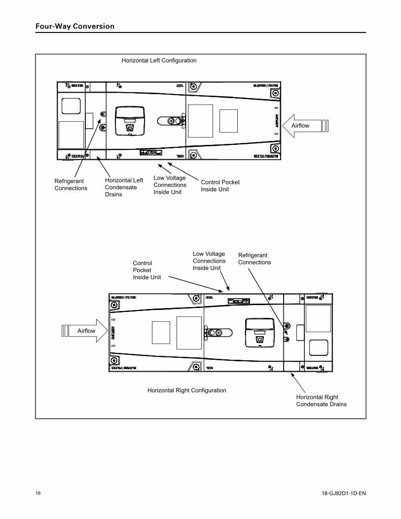
Airflow
Refrigerant Connections
Horizontal Left Condensate Drains
Low Voltage Connections Inside Unit
Control Pocket Inside Unit
Horizontal Left Configuration
Horizontal Right Configuration
Airflow
Control Pocket Inside Unit
Low Voltage Connections Inside Unit
Refrigerant Connections
Horizontal Right Condensate Drains
FFoouurr--WWaayy CCoonnvveerrssiioonn
18-GJ82D1-1D-EN 17
Ducted and Non-Ducted Return Applications
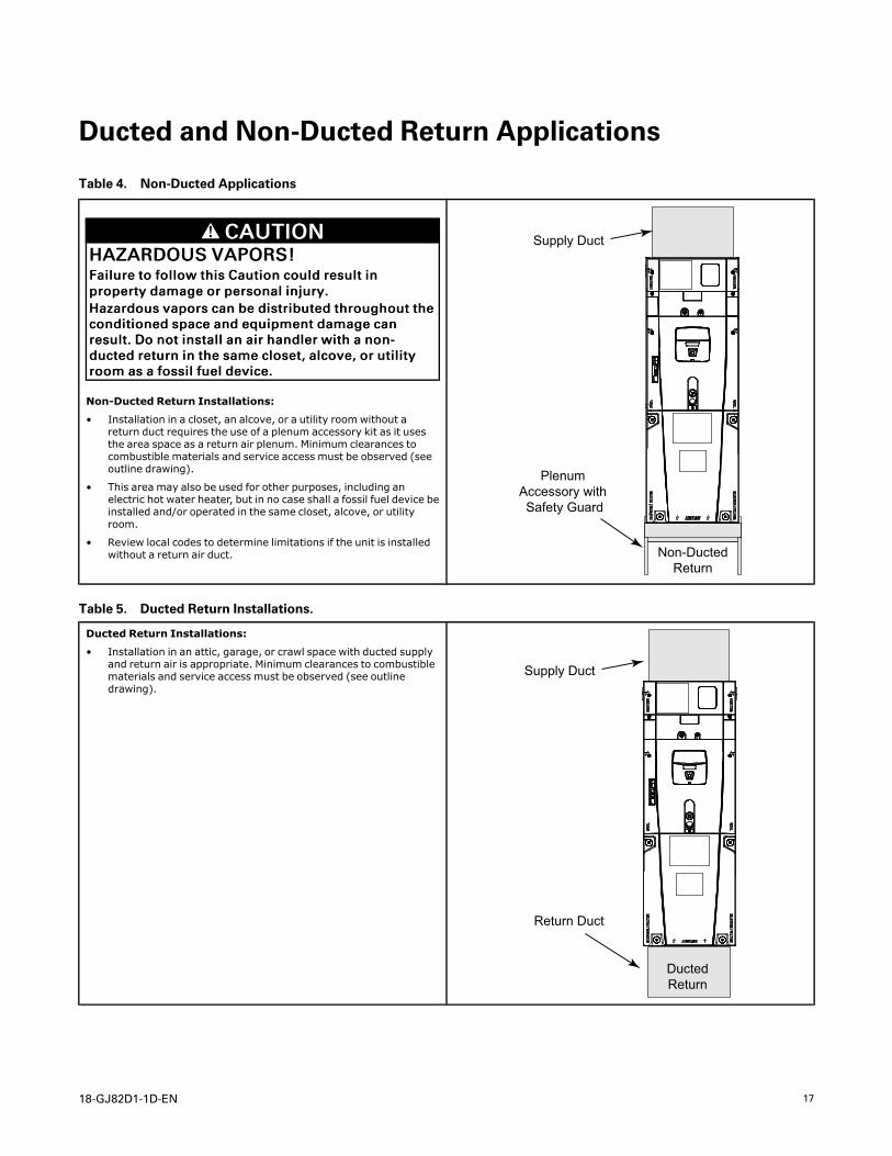
Table 4. Non-Ducted Applications
CCAAUUTTIIOONNHHAAZZAARRDDOOUUSS VVAAPPOORRSS!!FFaaiilluurree ttoo ffoollllooww tthhiiss CCaauuttiioonn ccoouulldd rreessuulltt iinnpprrooppeerrttyy ddaammaaggee oorr ppeerrssoonnaall iinnjjuurryy..HHaazzaarrddoouuss vvaappoorrss ccaann bbee ddiissttrriibbuutteedd tthhrroouugghhoouutt tthheeccoonnddiittiioonneedd ssppaaccee aanndd eeqquuiippmmeenntt ddaammaaggee ccaannrreessuulltt.. DDoo nnoott iinnssttaallll aann aaiirr hhaannddlleerr wwiitthh aa nnoonn--dduucctteedd rreettuurrnn iinn tthhee ssaammee cclloosseett,, aallccoovvee,, oorr uuttiilliittyyrroooomm aass aa ffoossssiill ffuueell ddeevviiccee..
Non-Ducted Return Installations:
• Installation in a closet, an alcove, or a utility room without areturn duct requires the use of a plenum accessory kit as it usesthe area space as a return air plenum. Minimum clearances tocombustible materials and service access must be observed (seeoutline drawing).
• This area may also be used for other purposes, including anelectric hot water heater, but in no case shall a fossil fuel device beinstalled and/or operated in the same closet, alcove, or utilityroom.
• Review local codes to determine limitations if the unit is installedwithout a return air duct.
Supply Duct
Plenum Accessory with Safety Guard
Non-DuctedReturn
Table 5. Ducted Return Installations.
Ducted Return Installations:
• Installation in an attic, garage, or crawl space with ducted supplyand return air is appropriate. Minimum clearances to combustiblematerials and service access must be observed (see outlinedrawing).
Supply Duct
Return Duct
DuctedReturn
18 18-GJ82D1-1D-EN
Additional Unit Preparation Considerations
For proper installation the following items must beconsidered prior to moving the unit to its installationsite:
• Pursuant to Florida Building Code 13–610.2A.2.1,this unit meets the criteria for a factory sealed airhandler.
• If a side return is needed for your application, theside return MUST be prepared prior to moving theair handler to its installation location. See the SideReturn Kit #BAYSRKIT100A Installer Guide fordetailed instructions, if used.
• When the air handler is located adjacent to theliving area, the system should be carefully designedwith returns which minimize noise transmissionthrough the return air grill. Although the air handleris designed with large blowers operating atmoderate speeds, any blower moving a highvolume of air will produce audible noise whichcould be objectionable when the unit is located veryclose to a living area. It is often advisable to routethe return ducts under the floor through the attic.Such design permits the installation of air returnremote from the living area (i.e. central hall).
• Study the unit’s outline drawing and dimensionsprior to selecting the installation site. Note inadvance which electrical conduit entry points andcondensate drain holes are to be used, so thatproper clearance allowances can be made forinstallation and future maintenance.
• Installation of the air handler must be made prior to, or at the same time as, the installation of theoutdoor unit in order to allow access for refrigerantlines.
• Consider the overall space needed when externalaccessories are used, additional height and widthrequirements may exist.
• These units are not approved for outdoorinstallation.
• These units must be installed in the proper air flowdirection.
• Any third-party heater accessories or hydronic coilsmust be downstream of the unit.
NNoottee:: No atomizing style humidifier is allowed in thereturn plenum with the use of this unit.
• Excessive bypass air may cause water blow-off,which will adversely affect system operation and aircleaner performance. To verify bypass airflow,follow the Bypass Humidifier Pre-InstallationCheckout and Set-Up Procedures available throughyour local distributor. Ask for publication number18–CH37D1–* Steam and Flow-through Fan PowerDuct-mounted Humidifiers. Follow the humidifierinstallation instructions. These should only beinstalled on the supply air side of the system.
NNoottee:: The air handlers have been evaluated inaccordance with the Code of Federal Regulations,Chapter XX, Part 3280 or the equivalent.“SUITABLE FOR MOBILE HOME USE.”
NNoottee:: TThhiiss uunniitt iiss cceerrttiiffiieedd ttoo UULL 11999955.. TThhee iinntteerriioorrccaabbiinneett wwaallll mmeeeettss tthhee ffoolllloowwiinngg::
— UL94–5VA Flame Class Listed
— UL723 Steiner Tunnel Listed for 25/50 Flame/Smoke
— UL746C Listed for Exposure to Ultraviolet Light,Water Exposure and Immersion

18-GJ82D1-1D-EN 19
Setting the Unit — Vertical Installation
Table 6. Considerations
Provide a minimum height of 14 inches for proper unrestricted airflowbelow the unit. Allow a minimum of 21 inches clearance in front of theair handler to permit maintenance and removal of filter.
• Position unit on suitable foundation. If a manufacturer approvedaccessory is not used, a frame strong enough to support the totalweight of the unit, accessories, and duct work must be provided.
• Isolate unit from the foundation using a suitable isolatingmaterial.
Note: The following sound insulation kits are available to lessenobjectionable sound.
BAYINSKT175A for use with 17.5” cabinetsBAYINSKT215A for use with 21.5” cabinetsBAYINSKT235A for use with 23.5” cabinets
Typical Closet Installation
Table 7. Upflow Installation
TASB Installation
1. Install the TASB plenum stand with integrated sound baffle usingthe TASB instructions.
Note: Kit is used for open air applications.
TASB175SB for use with 17.5” cabinetsTASB215SB for use with 21.5” cabinetsTASB235SB for use with 23.5” cabinetsMITISRKIT1620 — Side return kit with 16” x 20” filter
Contact your distributor for more information.
Note: The following sound insulation kits are available to lessenobjectionable sound.
BAYINSKT175A for use with 17.5” cabinetsBAYINSKT215A for use with 21.5” cabinetsBAYINSKT235A for use with 23.5” cabinets
Airflo
w
AirflowAirflow
Typical TASB Installation
20 18-GJ82D1-1D-EN
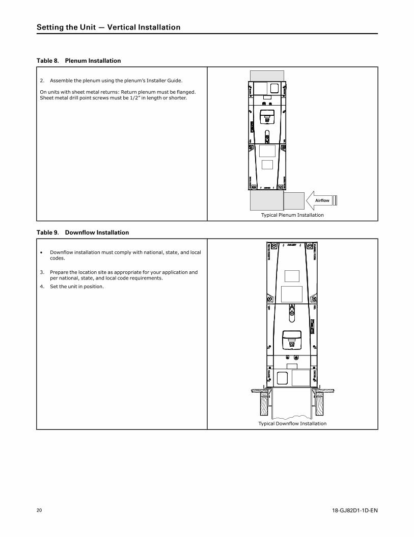
Table 8. Plenum Installation
2. Assemble the plenum using the plenum’s Installer Guide.
On units with sheet metal returns: Return plenummust be flanged.Sheet metal drill point screws must be 1/2” in length or shorter.
Airflow
Typical Plenum Installation
Table 9. Downflow Installation
• Downflow installation must comply with national, state, and localcodes.
3. Prepare the location site as appropriate for your application andper national, state, and local code requirements.
4. Set the unit in position.
Typical Downflow Installation
SSeettttiinngg tthhee UUnniitt —— VVeerrttiiccaall IInnssttaallllaattiioonn
18-GJ82D1-1D-EN 21
Setting the Unit — Horizontal Installations
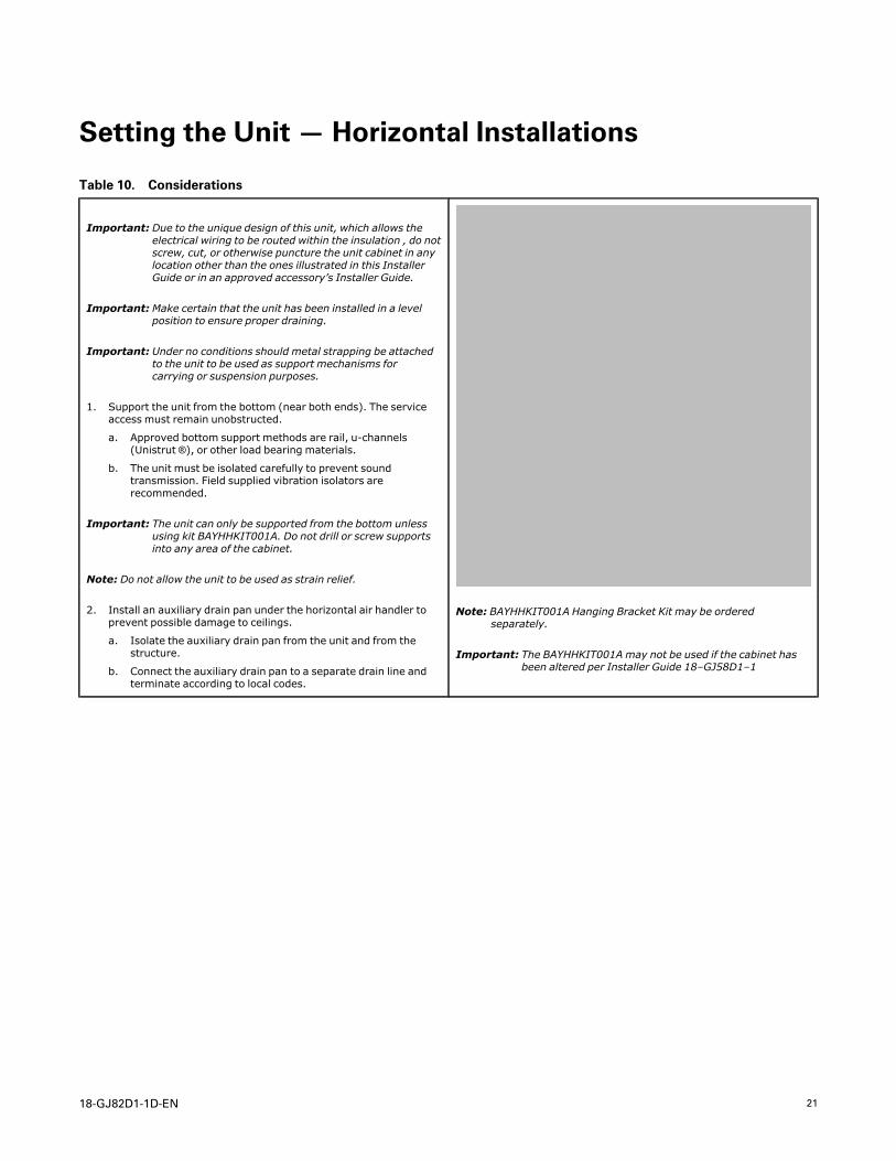
Table 10. Considerations
Important: Due to the unique design of this unit, which allows theelectrical wiring to be routed within the insulation , do notscrew, cut, or otherwise puncture the unit cabinet in anylocation other than the ones illustrated in this InstallerGuide or in an approved accessory’s Installer Guide.
Important:Make certain that the unit has been installed in a levelposition to ensure proper draining.
Important: Under no conditions should metal strapping be attachedto the unit to be used as support mechanisms forcarrying or suspension purposes.
1. Support the unit from the bottom (near both ends). The serviceaccess must remain unobstructed.
a. Approved bottom support methods are rail, u-channels(Unistrut ®), or other load bearing materials.
b. The unit must be isolated carefully to prevent soundtransmission. Field supplied vibration isolators arerecommended.
Important: The unit can only be supported from the bottom unlessusing kit BAYHHKIT001A. Do not drill or screw supportsinto any area of the cabinet.
Note: Do not allow the unit to be used as strain relief.
2. Install an auxiliary drain pan under the horizontal air handler toprevent possible damage to ceilings.
a. Isolate the auxiliary drain pan from the unit and from thestructure.
b. Connect the auxiliary drain pan to a separate drain line andterminate according to local codes.
Note: BAYHHKIT001A Hanging Bracket Kit may be orderedseparately.
Important: The BAYHHKIT001A may not be used if the cabinet hasbeen altered per Installer Guide 18–GJ58D1–1
22 18-GJ82D1-1D-EN
Connecting the Duct work
Table 11. Duct Connection Considerations
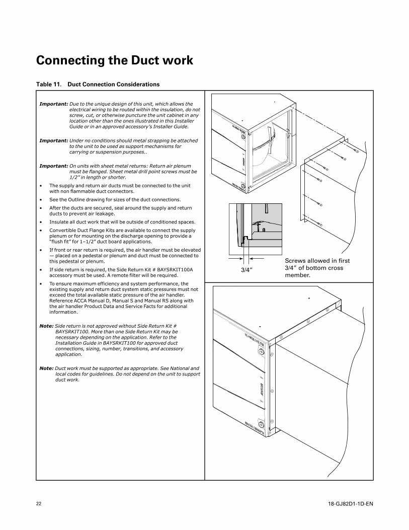
Important: Due to the unique design of this unit, which allows theelectrical wiring to be routed within the insulation, do notscrew, cut, or otherwise puncture the unit cabinet in anylocation other than the ones illustrated in this InstallerGuide or in an approved accessory’s Installer Guide.
Important: Under no conditions should metal strapping be attachedto the unit to be used as support mechanisms forcarrying or suspension purposes..
Important: On units with sheet metal returns: Return air plenummust be flanged. Sheet metal drill point screws must be1/2” in length or shorter.
• The supply and return air ducts must be connected to the unitwith non flammable duct connectors.
• See the Outline drawing for sizes of the duct connections.
• After the ducts are secured, seal around the supply and returnducts to prevent air leakage.
• Insulate all duct work that will be outside of conditioned spaces.
• Convertible Duct Flange Kits are available to connect the supplyplenum or for mounting on the discharge opening to provide a“flush fit” for 1–1/2” duct board applications.
• If front or rear return is required, the air handler must be elevated— placed on a pedestal or plenum and duct must be connected tothis pedestal or plenum.
• If side return is required, the Side Return Kit # BAYSRKIT100Aaccessory must be used. A remote filter will be required.
• To ensure maximum efficiency and system performance, theexisting supply and return duct system static pressures must notexceed the total available static pressure of the air handler.Reference ACCA Manual D, Manual S and Manual RS along withthe air handler Product Data and Service Facts for additionalinformation.
Note: Side return is not approved without Side Return Kit #BAYSRKIT100. More than one Side Return Kit may benecessary depending on the application. Refer to theInstallation Guide in BAYSRKIT100 for approved ductconnections, sizing, number, transitions, and accessoryapplication.
Note: Duct work must be supported as appropriate. See National andlocal codes for guidelines. Do not depend on the unit to supportduct work.
3/4”
Screws allowed in first 3/4” of bottom cross member.
18-GJ82D1-1D-EN 23
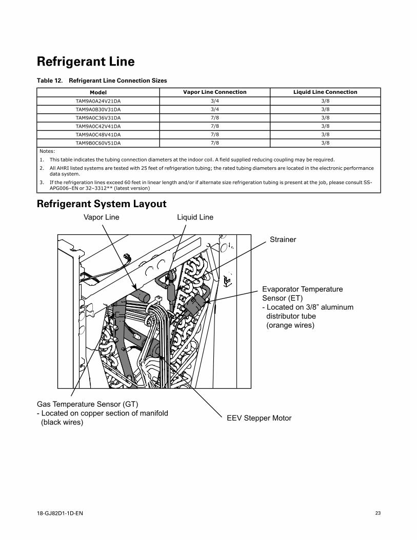
Refrigerant LineTable 12. Refrigerant Line Connection Sizes
Model Vapor Line Connection Liquid Line Connection
TAM9A0A24V21DA 3/4 3/8
TAM9A0B30V31DA 3/4 3/8
TAM9A0C36V31DA 7/8 3/8
TAM9A0C42V41DA 7/8 3/8
TAM9A0C48V41DA 7/8 3/8
TAM9B0C60V51DA 7/8 3/8
Notes:
1. This table indicates the tubing connection diameters at the indoor coil. A field supplied reducing coupling may be required.
2. All AHRI listed systems are tested with 25 feet of refrigeration tubing; the rated tubing diameters are located in the electronic performancedata system.
3. If the refrigeration lines exceed 60 feet in linear length and/or if alternate size refrigeration tubing is present at the job, please consult SS-APG006–EN or 32–3312** (latest version)
Refrigerant System LayoutVapor Line Liquid Line
Strainer
Evaporator TemperatureSensor (ET)- Located on 3/8” aluminum distributor tube (orange wires)
EEV Stepper Motor
Gas Temperature Sensor (GT)- Located on copper section of manifold (black wires)
24 18-GJ82D1-1D-EN
Refrigerant Line Brazing
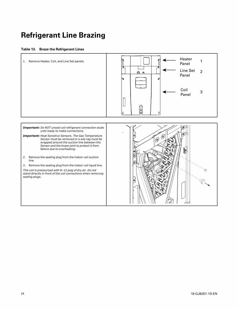
Table 13. Braze the Refrigerant Lines
1. Remove Heater, Coil, and Line Set panels.Heater Panel
Line Set Panel
CoilPanel
1
2
3
Important: Do NOT unseal coil refrigerant connection stubsuntil ready to make connections.
Important: Heat Sensitive Sensors. The Gas TemperatureSensor must be removed or a wet rag must bewrapped around the suction line between theSensor and the braze joint to protect it fromfailure due to overheating.
2. Remove the sealing plug from the indoor coil suctionline.
3. Remove the sealing plug from the indoor coil liquid line.
This coil is pressurized with 8–12 psig of dry air. Do notstand directly in front of the coil connections when removingsealing plugs.
18-GJ82D1-1D-EN 25
Table 13. Braze the Refrigerant Lines (continued)
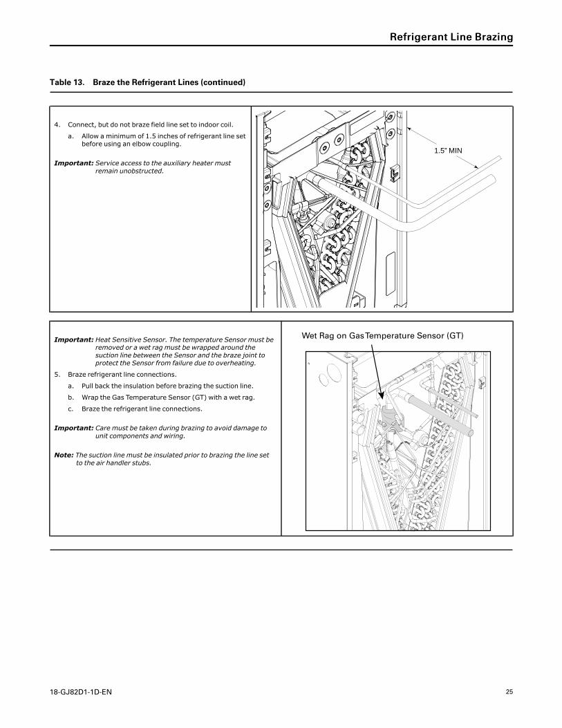
4. Connect, but do not braze field line set to indoor coil.
a. Allow a minimum of 1.5 inches of refrigerant line setbefore using an elbow coupling.
Important: Service access to the auxiliary heater mustremain unobstructed.
1.5” MIN
Important: Heat Sensitive Sensor. The temperature Sensor must beremoved or a wet rag must be wrapped around thesuction line between the Sensor and the braze joint toprotect the Sensor from failure due to overheating.
5. Braze refrigerant line connections.
a. Pull back the insulation before brazing the suction line.
b. Wrap the Gas Temperature Sensor (GT) with a wet rag.
c. Braze the refrigerant line connections.
Important: Care must be taken during brazing to avoid damage tounit components and wiring.
Note: The suction line must be insulated prior to brazing the line setto the air handler stubs.
Wet Rag on Gas Temperature Sensor (GT)
RReeffrriiggeerraanntt LLiinnee BBrraazziinngg
26 18-GJ82D1-1D-EN
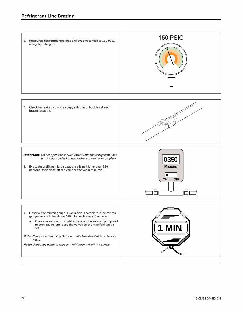
6. Pressurize the refrigerant lines and evaporator coil to 150 PSIGusing dry nitrogen.
150 PSIG
7. Check for leaks by using a soapy solution or bubbles at eachbrazed location.
Important: Do not open the service valves until the refrigerant linesand indoor coil leak check and evacuation are complete.
8. Evacuate until the micron gauge reads no higher than 350microns, then close off the valve to the vacuum pump.
0350Microns
ON OFF
9. Observe the micron gauge. Evacuation is complete if the microngauge does not rise above 500 microns in one (1) minute.
a. Once evacuation is complete blank off the vacuum pump andmicron gauge, and close the valves on the manifold gaugeset.
Note: Charge system using Outdoor unit’s Installer Guide or ServiceFacts.
Note: Use soapy water to wipe any refrigerant oil off the panels.
1 MIN.
RReeffrriiggeerraanntt LLiinnee BBrraazziinngg
18-GJ82D1-1D-EN 27
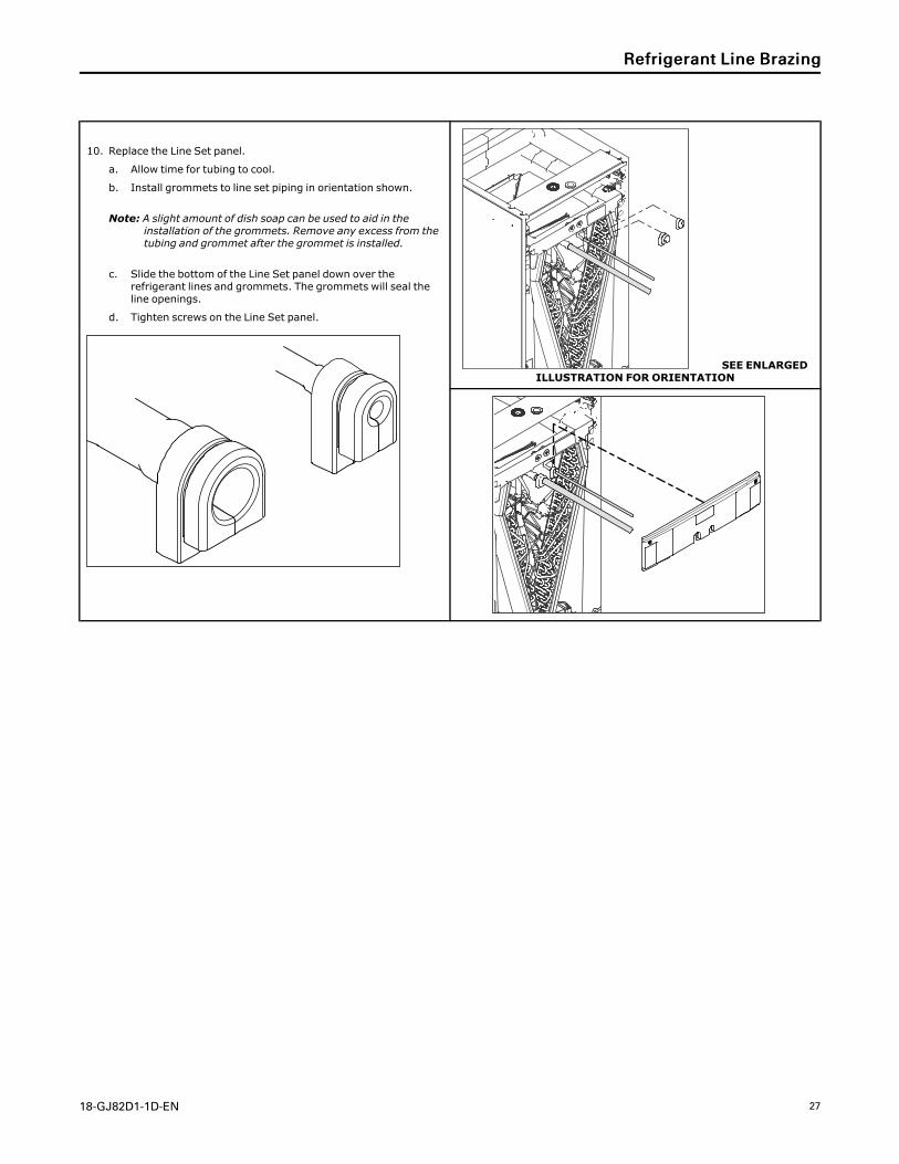
10. Replace the Line Set panel.
a. Allow time for tubing to cool.
b. Install grommets to line set piping in orientation shown.
Note: A slight amount of dish soap can be used to aid in theinstallation of the grommets. Remove any excess from thetubing and grommet after the grommet is installed.
c. Slide the bottom of the Line Set panel down over therefrigerant lines and grommets. The grommets will seal theline openings.
d. Tighten screws on the Line Set panel.
SEE ENLARGEDILLUSTRATION FOR ORIENTATION
RReeffrriiggeerraanntt LLiinnee BBrraazziinngg
28 18-GJ82D1-1D-EN
Condensate Drain Piping
Condensate Drain Piping Considerations
• Condensate drain plumbing must comply with national, state, andlocal codes.
• Route condensate drain lines away from air handler so they do notinterfere with access panels.
• Slope the drain lines downward a minimum of 1/4” per foot,support per local codes.
• Do not use reducing fittings in the condensate drain lines.
• Do not connect the drain line to a closed drain system.
• Do not use a torch or flame near the plastic drain pan coupling.
• A P-trap is not required for proper drainage due to the positivepressure of the air handler; however, it is recommended toprevent efficiency loss of conditioned air.
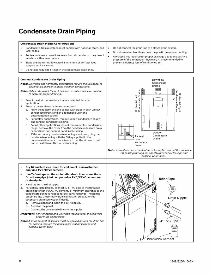
Connect Condensate Drain Piping
Note: Downflow and horizontal orientations require the Coil panel tobe removed in order to make the drain connections.
Note: Make certain that the unit has been installed in a level positionto allow for proper draining.
1. Select the drain connections that are oriented for yourapplication.
2. Prepare the condensate drain connections.a. From the factory, the unit comes with plugs in both upflow
condensate drains and an additional plug in thedocumentation packet.
b. For upflow applications, remove upflow condensate plug(s)and connect condensate piping.
c. For all other applications, do not remove upflow condensateplugs. Remove the cover from the needed condensate drainconnections and connect condensate piping.
d. If the secondary condensate opening is not used, plug thecondensate opening with the fitting supplied in thedocumentation pack. Use scissors to cut the air seal in halfand re-install over the unused opening.
SP
SP
SP
S
P
Downflow Condensate Drains
Ho
rizo
nta
l Lef
t C
on
den
sate
Dra
ins
Ho
rizon
tal Rig
ht
Co
nd
ensate D
rains
Upflow Condensate Drains
Air seal over secondary drain
Note: A small amount of sealant must be applied around the drain line(s) passing through the panel to prevent air leakage and
possible water drips.
• Dry fit and test clearance for coil panel removal beforeapplying PVC/CPVC cement.
• Use Teflon tape on the air handler drain line connections.Do not use pipe joint compound or PVC/CPVC cement ondrain nipple.
• Hand tighten the drain pipe.3. For upflow installations, connect 3/4” PVC pipe to the threaded
drain nipple with PVC/CPVC cement. 3” minimum clearance to thecondensate piping is needed for coil panel removal. Thread theassembly into the primary drain connection (repeat for thesecondary drain connection if used).a. Remove panel and insert the 3/4” nipples.b. Reinstall the panel.c. Connect the condensate lines to the nipples.
Important: For Horizontal and Downflow installations, the followingorder must be observed:
Note: A small amount of sealant must be applied around the drain line(s) passing through the panel to prevent air leakage andpossible water drips.
PVC CEMENT
Teflon Tape
Drain Nipple
3/4” PVC Pipe
PVC/CPVC Cement
18-GJ82D1-1D-EN 29
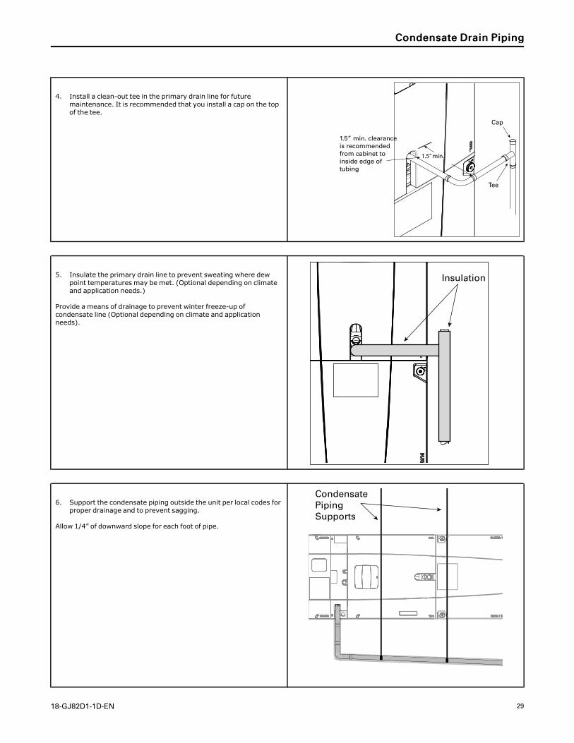
4. Install a clean-out tee in the primary drain line for futuremaintenance. It is recommended that you install a cap on the topof the tee.
1.5” min.
Cap
Tee
1.5” min. clearance is recommended from cabinet to inside edge of tubing
5. Insulate the primary drain line to prevent sweating where dewpoint temperatures may be met. (Optional depending on climateand application needs.)
Provide a means of drainage to prevent winter freeze-up ofcondensate line (Optional depending on climate and applicationneeds).
Insulation
6. Support the condensate piping outside the unit per local codes forproper drainage and to prevent sagging.
Allow 1/4” of downward slope for each foot of pipe.
Condensate Piping Supports
CCoonnddeennssaattee DDrraaiinn PPiippiinngg
30 18-GJ82D1-1D-EN
Electrical — Low Voltage
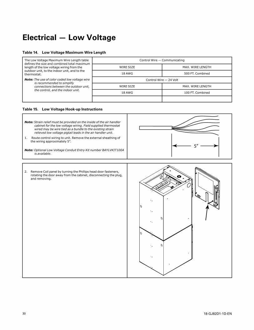
Table 14. Low Voltage MaximumWire Length
The Low Voltage MaximumWire Length tabledefines the size and combined total maximumlength of the low voltage wiring from theoutdoor unit, to the indoor unit, and to thethermostat.
Note: The use of color coded low voltage wireis recommended to simplifyconnections between the outdoor unit,the control, and the indoor unit.
Control Wire — Communicating
WIRE SIZE MAX. WIRE LENGTH
18 AWG 500 FT. Combined
Control Wire — 24 Volt
WIRE SIZE MAX. WIRE LENGTH
18 AWG 100 FT. Combined
Table 15. Low Voltage Hook-up Instructions
Note: Strain relief must be provided on the inside of the air handlercabinet for the low voltage wiring. Field supplied thermostatwired may be wire tied as a bundle to the existing strainrelieved low voltage pigtail leads in the air handler unit.
1. Route control wiring to unit. Remove the external sheathing ofthe wiring approximately 5”.
Note: Optional Low Voltage Conduit Entry Kit number BAYLVKIT100Ais available.
5”
2. Remove Coil panel by turning the Phillips head door fasteners,rotating the door away from the cabinet, disconnecting the plug,and removing.
18-GJ82D1-1D-EN 31
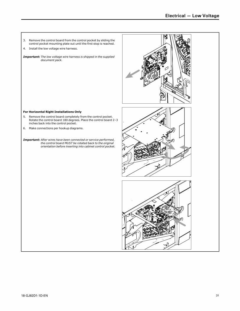
3. Remove the control board from the control pocket by sliding thecontrol pocket mounting plate out until the first stop is reached.
4. Install the low voltage wire harness.
Important: The low voltage wire harness is shipped in the supplieddocument pack.
For Horizontal Right Installations Only
5. Remove the control board completely from the control pocket.Rotate the control board 180 degrees. Place the control board 2–3inches back into the control pocket.
6. Make connections per hookup diagrams.
Important: After wires have been connected or service performed,the control board MUST be rotated back to the originalorientation before inserting into cabinet control pocket.
EElleeccttrriiccaall —— LLooww VVoollttaaggee
32 18-GJ82D1-1D-EN
B/C
R
D
ODT
ODT
RS1
RS1
R
B
D
B
D
OptionalOutdoorSensor*
OptionalRemoteSensor*
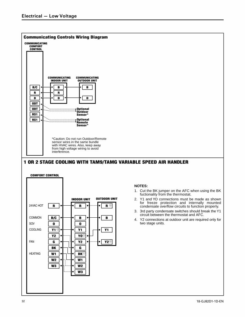
Communicating Controls Wiring Diagram
COMMUNICATINGINDOOR UNIT
COMMUNICATINGOUTDOOR UNIT
COMMUNICATING COMFORT CONTROL
*Caution: Do not run Outdoor/Remote sensor wires in the same bundle with HVAC wires. Also, keep away from high voltage wiring to avoid interference.
24VAC HOT
COMMON
SOV
COOLING
FAN
HEATING
R
B/C
O
Y1
Y2
G
BK
W1
W2
W3
O
R
B
Y1
YO
W3
Y2
G
BK
W1
W2
R
B
Y1
Y2
3
2
1
4
4
COMFORT CONTROL
1 OR 2 STAGE COOLING WITH TAM9/TAMG VARIABLE SPEED AIR HANDLER
INDOOR UNIT OUTDOOR UNIT
NOTES:1. Cut the BK jumper on the AFC when using the BK
fuctionality from the thermostat.2. Y1 and YO connections must be made as shown
for freeze protection and internally mounted condensate overflow circuits to function properly.
3. 3rd party condensate switches should break the Y1 circuit between the thermostat and AFC.
4. Y2 connections at outdoor unit are required only for two stage units.
EElleeccttrriiccaall —— LLooww VVoollttaaggee
18-GJ82D1-1D-EN 33
24VAC HOT
COMMON
SOV
COOLING
FAN
HEATING
R
B/C
O
Y1
Y2
Y1
YO
G
BK
W1
W2
Y2 Y2
G
BK
W1W3
W2
W3
O
Y1
O
R
B
R
X2
B
3 2
4
2
1
COMFORT CONTROL
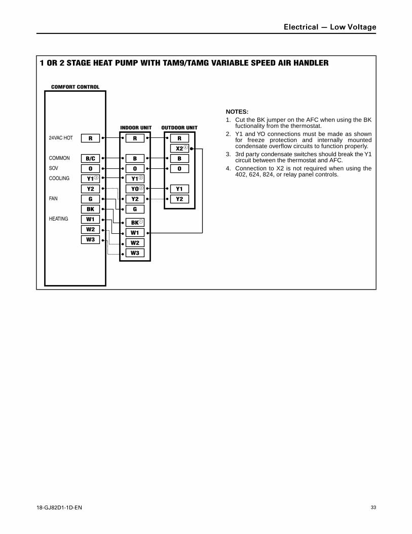
1 OR 2 STAGE HEAT PUMP WITH TAM9/TAMG VARIABLE SPEED AIR HANDLER
INDOOR UNIT OUTDOOR UNIT
NOTES:1. Cut the BK jumper on the AFC when using the BK
fuctionality from the thermostat.2. Y1 and YO connections must be made as shown
for freeze protection and internally mounted condensate overflow circuits to function properly.
3. 3rd party condensate switches should break the Y1 circuit between the thermostat and AFC.
4. Connection to X2 is not required when using the 402, 624, 824, or relay panel controls.
EElleeccttrriiccaall —— LLooww VVoollttaaggee
34 18-GJ82D1-1D-EN
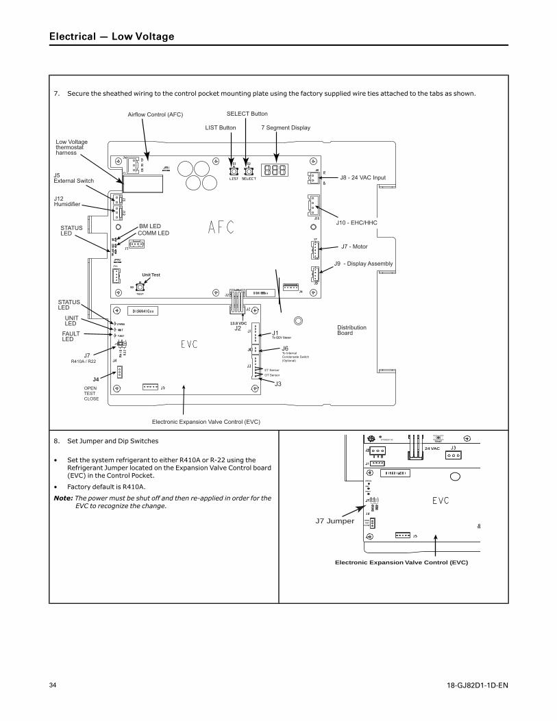
7. Secure the sheathed wiring to the control pocket mounting plate using the factory supplied wire ties attached to the tabs as shown.
SELECT Button
7 Segment DisplayLIST Button
Electronic Expansion Valve Control (EVC)
Airflow Control (AFC)
J10 - EHC/HHC
J7R410A / R22
J4
OPENTESTCLOSE
STATUS LED
BM LEDCOMM LED
Unit Test
J3
J6
J1To EEV Stator
To Internal Condensate Switch (Optional)
GT Sensor
ET Sensor
J213.8 VDC
Distribution Board
J7 - Motor
J8 - 24 VAC Input
J9 - Display Assembly
J5External Switch
J12Humidifier
Low Voltage thermostat harness
STATUS LED
FAULT LED
UNIT LED
8. Set Jumper and Dip Switches
• Set the system refrigerant to either R410A or R-22 using theRefrigerant Jumper located on the Expansion Valve Control board(EVC) in the Control Pocket.
• Factory default is R410A.
Note: The power must be shut off and then re-applied in order for theEVC to recognize the change.
2 1
R2 2
3
R41
0
J7 JumperGAS
TEMPGAS
TEMP
Electronic Expansion Valve Control (EVC)
TEST
CLOSE
OPEN
TEST
24 VAC
FAULT
UNIT
STATUS
D156231 H
EElleeccttrriiccaall —— LLooww VVoollttaaggee
18-GJ82D1-1D-EN 35
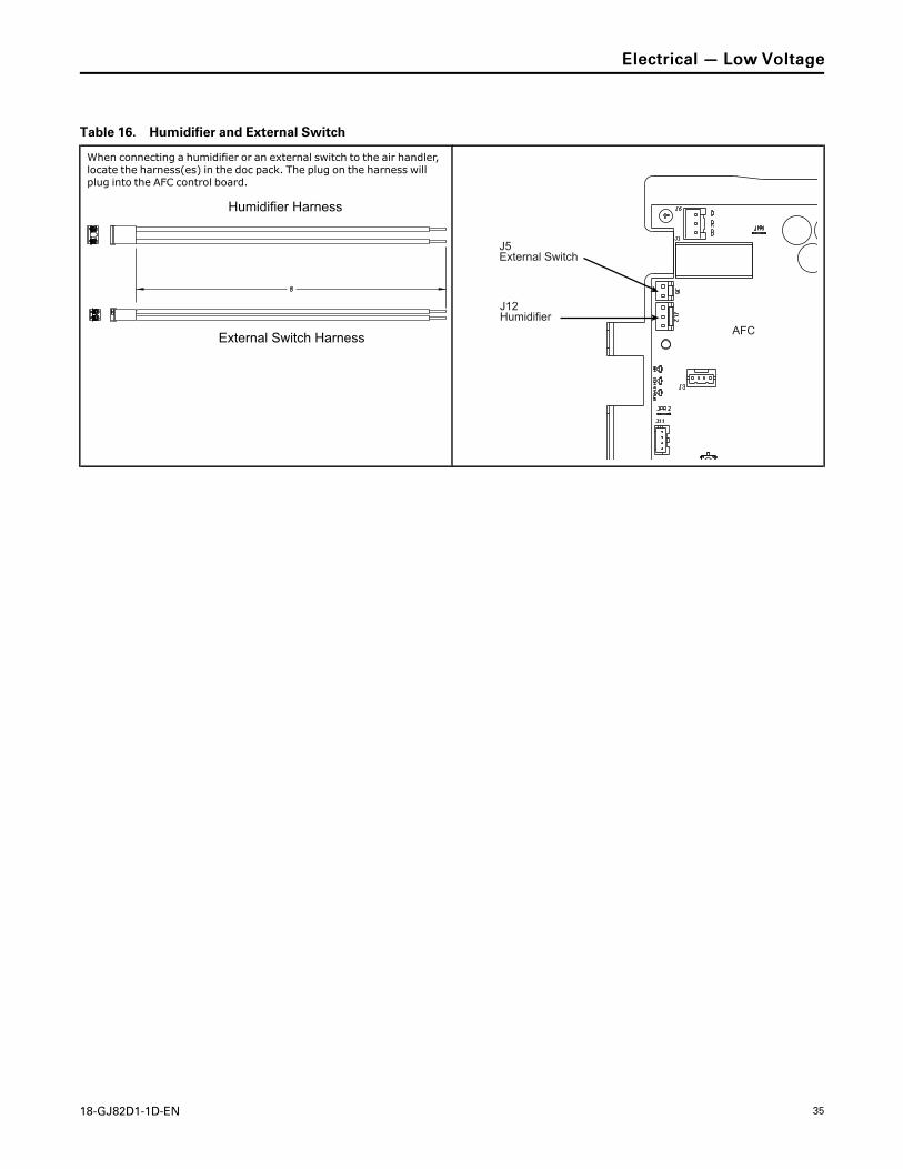
Table 16. Humidifier and External Switch
When connecting a humidifier or an external switch to the air handler,locate the harness(es) in the doc pack. The plug on the harness willplug into the AFC control board.
Humidifier Harness
External Switch Harness AFC
J5External Switch
J12Humidifier
EElleeccttrriiccaall —— LLooww VVoollttaaggee
36 18-GJ82D1-1D-EN
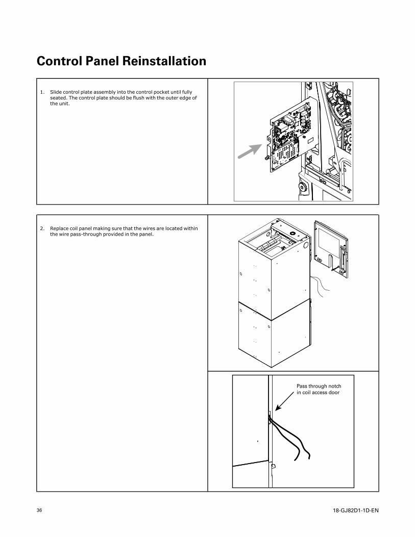
Control Panel Reinstallation
1. Slide control plate assembly into the control pocket until fullyseated. The control plate should be flush with the outer edge ofthe unit.
2. Replace coil panel making sure that the wires are located withinthe wire pass-through provided in the panel.
Pass through notch in coil access door
18-GJ82D1-1D-EN 37
Electrical — High Voltage
Table 17. High Voltage Power Supply
The high voltage power supply must match the equipment nameplate.
Power wiring, including ground wiring must comply with national,sate, and local codes.
Field wiring diagrams for supplementary electric heaters are shippedwith the heaters.
WWAARRNNIINNGGLLIIVVEE EELLEECCTTRRIICCAALL CCOOMMPPOONNEENNTTSS!!FFaaiilluurree ttoo ffoollllooww tthhiiss WWaarrnniinngg ccoouulldd rreessuulltt iinnpprrooppeerrttyy ddaammaaggee,, sseevveerree ppeerrssoonnaall iinnjjuurryy,, oorr ddeeaatthh..FFoollllooww aallll eelleeccttrriiccaall ssaaffeettyy pprreeccaauuttiioonnss wwhheenneexxppoosseedd ttoo lliivvee eelleeccttrriiccaall ccoommppoonneennttss.. IItt mmaayy bbeenneecceessssaarryy ttoo wwoorrkk wwiitthh lliivvee eelleeccttrriiccaall ccoommppoonneennttssdduurriinngg iinnssttaallllaattiioonn,, tteessttiinngg,, sseerrvviicciinngg,, aannddttrroouubblleesshhoooottiinngg ooff tthhiiss pprroodduucctt..
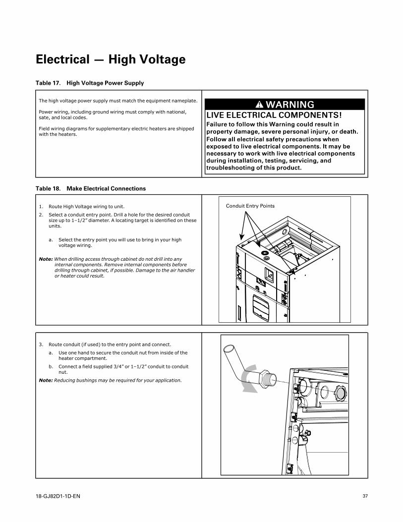
Table 18. Make Electrical Connections
1. Route High Voltage wiring to unit.
2. Select a conduit entry point. Drill a hole for the desired conduitsize up to 1–1/2” diameter. A locating target is identified on theseunits.
a. Select the entry point you will use to bring in your highvoltage wiring.
Note:When drilling access through cabinet do not drill into anyinternal components. Remove internal components beforedrilling through cabinet, if possible. Damage to the air handleror heater could result.
Conduit Entry Points
3. Route conduit (if used) to the entry point and connect.
a. Use one hand to secure the conduit nut from inside of theheater compartment.
b. Connect a field supplied 3/4” or 1–1/2” conduit to conduitnut.
Note: Reducing bushings may be required for your application.
38 18-GJ82D1-1D-EN
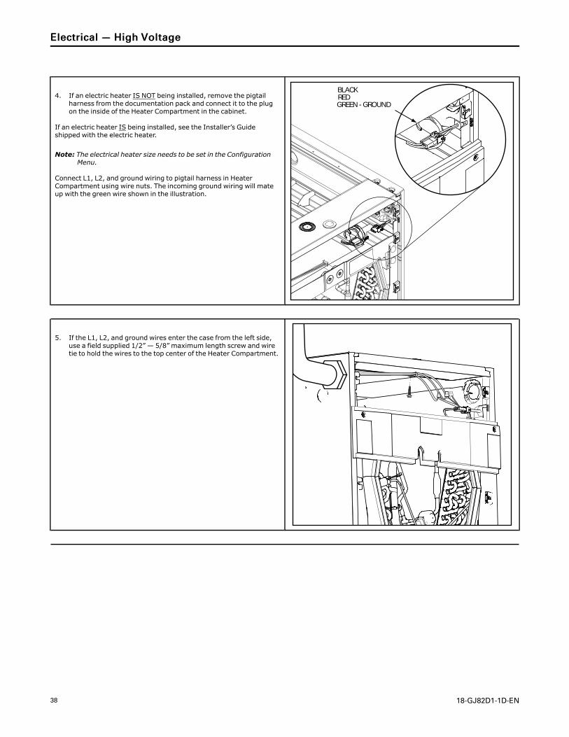
4. If an electric heater IS NOT being installed, remove the pigtailharness from the documentation pack and connect it to the plugon the inside of the Heater Compartment in the cabinet.
If an electric heater IS being installed, see the Installer’s Guideshipped with the electric heater.
Note: The electrical heater size needs to be set in the ConfigurationMenu.
Connect L1, L2, and ground wiring to pigtail harness in HeaterCompartment using wire nuts. The incoming ground wiring will mateup with the green wire shown in the illustration.
BLACKREDGREEN - GROUND
5. If the L1, L2, and ground wires enter the case from the left side,use a field supplied 1/2” — 5/8” maximum length screw and wiretie to hold the wires to the top center of the Heater Compartment.
EElleeccttrriiccaall —— HHiigghh VVoollttaaggee
18-GJ82D1-1D-EN 39
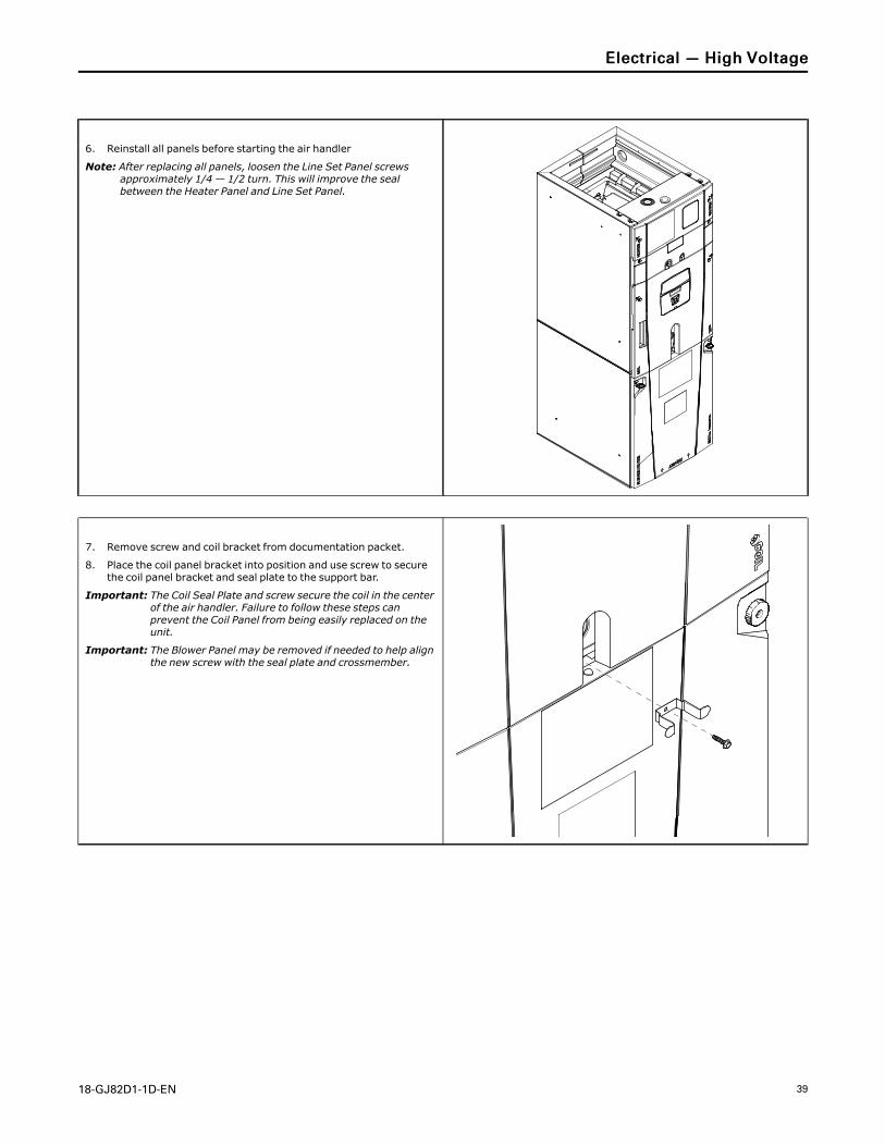
6. Reinstall all panels before starting the air handler
Note: After replacing all panels, loosen the Line Set Panel screwsapproximately 1/4 — 1/2 turn. This will improve the sealbetween the Heater Panel and Line Set Panel.
7. Remove screw and coil bracket from documentation packet.
8. Place the coil panel bracket into position and use screw to securethe coil panel bracket and seal plate to the support bar.
Important: The Coil Seal Plate and screw secure the coil in the centerof the air handler. Failure to follow these steps canprevent the Coil Panel from being easily replaced on theunit.
Important: The Blower Panel may be removed if needed to help alignthe new screw with the seal plate and crossmember.
EElleeccttrriiccaall —— HHiigghh VVoollttaaggee
40 18-GJ82D1-1D-EN
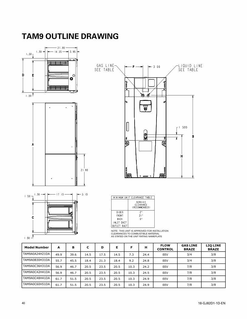
TAM9 OUTLINE DRAWING
NOTE: THIS UNIT IS APPROVED FOR INSTALLATIONCLEARANCES TO COMBUSTIBLE MATERIALAS STATED ON THE UNIT RATING NAMEPLATE
Model Number A B C D E F H FLOWCONTROL
GAS LINEBRAZE
LIQ LINEBRAZE
TAM9A0A24H21DA 49.9 39.6 14.5 17.5 14.5 7.3 24.4 EEV 3/4 3/8
TAM9A0B30H31DA 55.7 45.5 18.4 21.3 18.4 9.2 24.8 EEV 3/4 3/8
TAM9A0C36H31DA 56.9 46.7 20.5 23.5 20.5 10.3 24.2 EEV 7/8 3/8
TAM9A0C42H41DA 56.9 46.7 20.5 23.5 20.5 10.3 24.5 EEV 7/8 3/8
TAM9A0C48H41DA 61.7 51.5 20.5 23.5 20.5 10.3 24.9 EEV 7/8 3/8
TAM9A0C60H51DA 61.7 51.5 20.5 23.5 20.5 10.3 24.9 EEV 7/8 3/8
18-GJ82D1-1D-EN 41
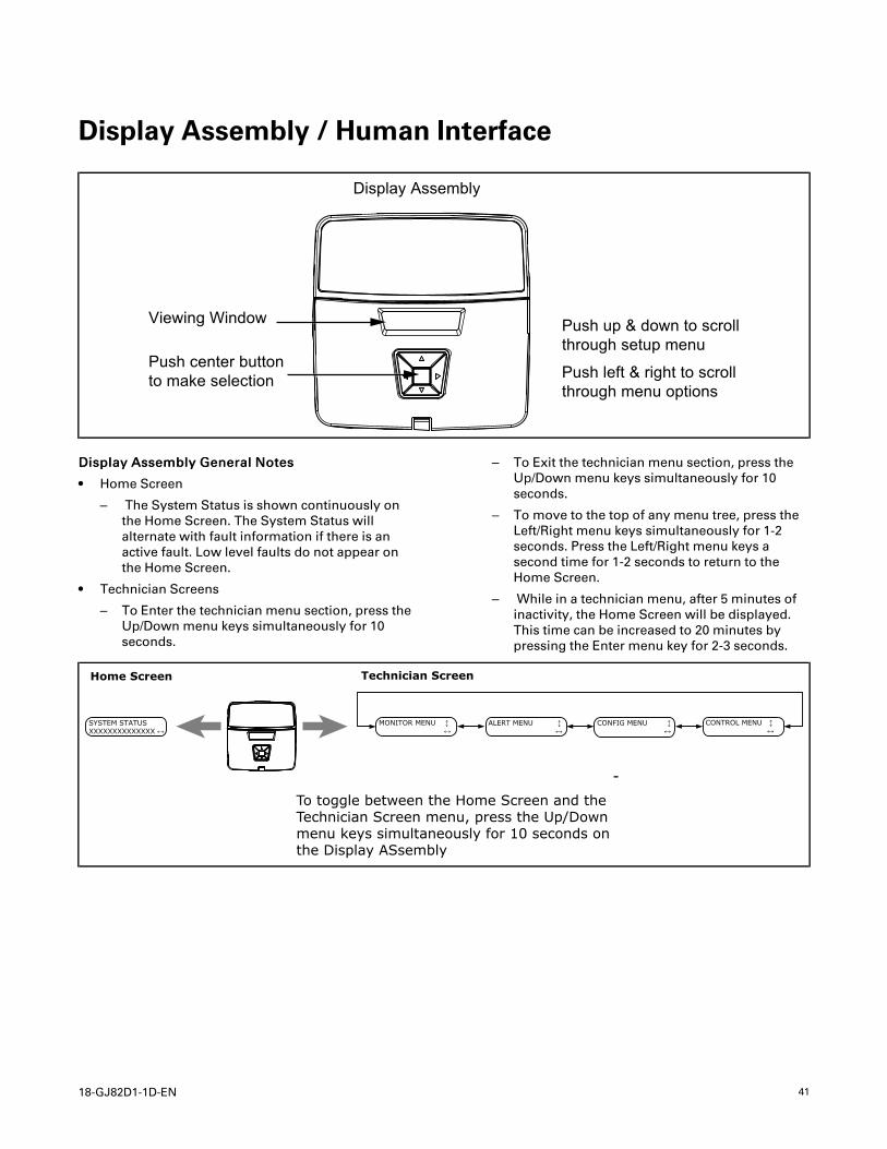
Display Assembly / Human Interface
Display Assembly
Viewing Window
Push center buttonto make selection
Push up & down to scrollthrough setup menu
Push left & right to scrollthrough menu options
DDiissppllaayy AAsssseemmbbllyy GGeenneerraall NNootteess
• Home Screen
– The System Status is shown continuously onthe Home Screen. The System Status willalternate with fault information if there is anactive fault. Low level faults do not appear onthe Home Screen.
• Technician Screens
– To Enter the technician menu section, press theUp/Down menu keys simultaneously for 10seconds.
– To Exit the technician menu section, press theUp/Down menu keys simultaneously for 10seconds.
– To move to the top of any menu tree, press theLeft/Right menu keys simultaneously for 1-2seconds. Press the Left/Right menu keys asecond time for 1-2 seconds to return to theHome Screen.
– While in a technician menu, after 5 minutes ofinactivity, the Home Screen will be displayed.This time can be increased to 20 minutes bypressing the Enter menu key for 2-3 seconds.
MONITOR MENU ↕ ↔
ALERT MENU ↕ ↔
Home Screen
SYSTEM STATUS XXXXXXXXXXXXXX ↔
Technician Screen
CONFIG MENU ↕ ↔
CONTROL MENU ↕ ↔
To toggle between the Home Screen and theTechnician Screen menu, press the Up/Downmenu keys simultaneously for 10 seconds onthe Display ASsembly
42 18-GJ82D1-1D-EN
TAM9— Technician Menu and Configuration tree
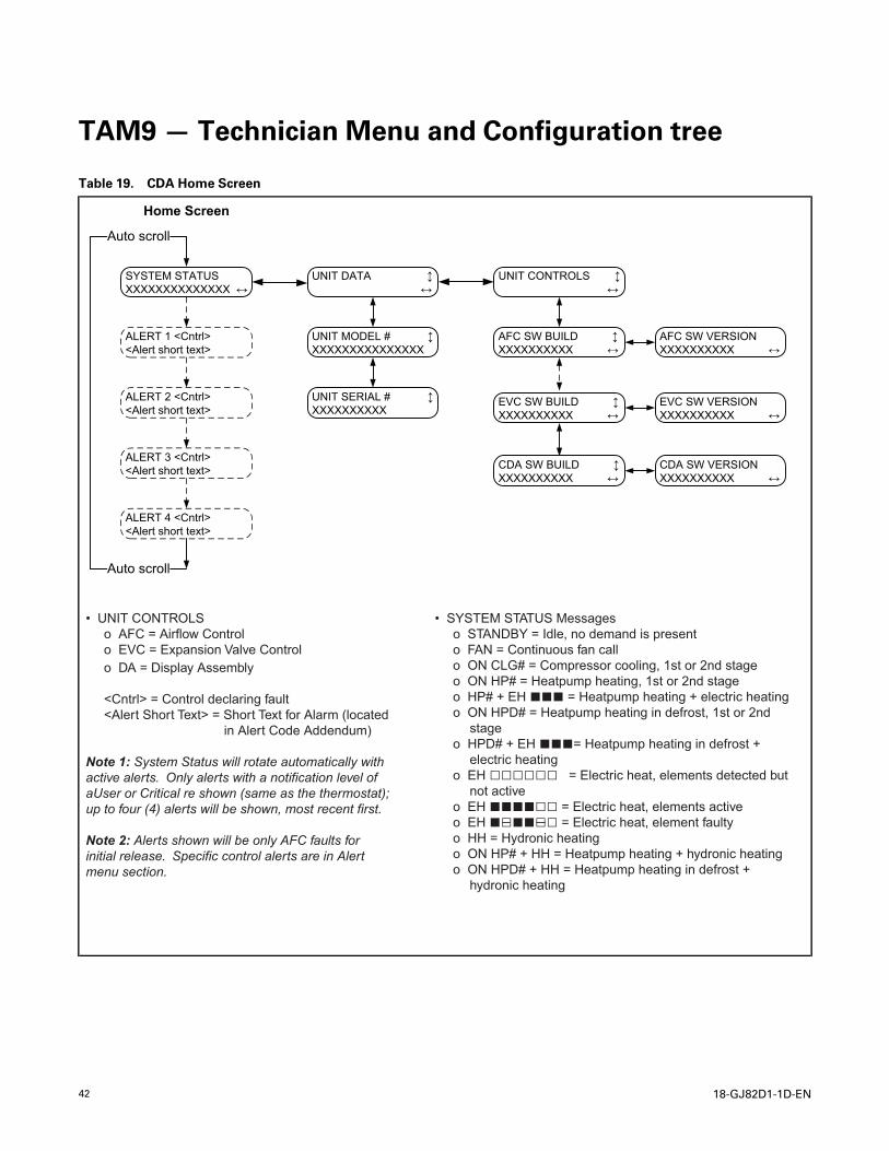
Table 19. CDA Home Screen
Home Screen
SYSTEM STATUS XXXXXXXXXXXXXX ↔
UNIT DATA ↕↔
UNIT SERIAL # ↕XXXXXXXXXX
UNIT CONTROLS ↕↔
AFC SW BUILD ↕XXXXXXXXXX ↔
EVC SW BUILD ↕XXXXXXXXXX ↔
AFC SW VERSIONXXXXXXXXXX ↔
EVC SW VERSIONXXXXXXXXXX ↔
UNIT MODEL # ↕XXXXXXXXXXXXXXX
ALERT 1 <Cntrl><Alert short text>
ALERT 2 <Cntrl><Alert short text>
ALERT 3 <Cntrl><Alert short text>
ALERT 4 <Cntrl><Alert short text>
Auto scroll
Auto scroll
CDA SW BUILD ↕XXXXXXXXXX ↔
CDA SW VERSIONXXXXXXXXXX ↔
• UNIT CONTROLS o AFC = Airflow Control o EVC = Expansion Valve Control o DA = Display Assembly
<Cntrl> = Control declaring fault <Alert Short Text> = Short Text for Alarm (located in Alert Code Addendum)
Note 1: System Status will rotate automatically with active alerts. Only alerts with a notification level of aUser or Critical re shown (same as the thermostat); up to four (4) alerts will be shown, most recent first.
Note 2: Alerts shown will be only AFC faults for initial release. Specific control alerts are in Alert menu section.
• SYSTEM STATUS Messages o STANDBY = Idle, no demand is present o FAN = Continuous fan call o ON CLG# = Compressor cooling, 1st or 2nd stage o ON HP# = Heatpump heating, 1st or 2nd stage o HP# + EH ■■■ = Heatpump heating + electric heating o ON HPD# = Heatpump heating in defrost, 1st or 2nd
stage o HPD# + EH ■■■= Heatpump heating in defrost +
electric heating o EH □□□□□□ = Electric heat, elements detected but
not active o EH ■■■■□□ = Electric heat, elements active o EH ■□■■□□ = Electric heat, element faulty o HH = Hydronic heating o ON HP# + HH = Heatpump heating + hydronic heating o ON HPD# + HH = Heatpump heating in defrost +
hydronic heating
18-GJ82D1-1D-EN 43
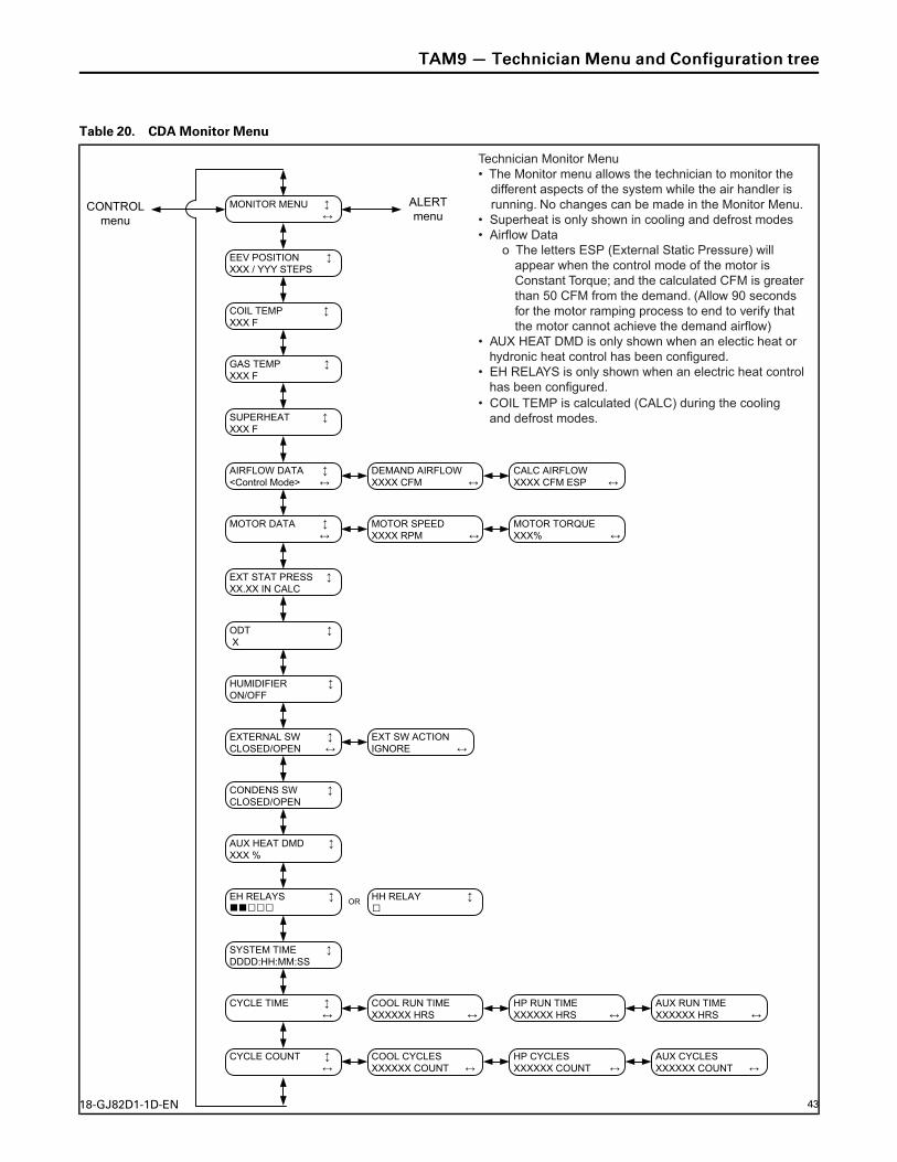
Table 20. CDA Monitor Menu
MONITOR MENU ↕↔
EEV POSITION ↕XXX / YYY STEPS
COIL TEMP ↕XXX F
GAS TEMP ↕XXX F
SUPERHEAT ↕XXX F
AIRFLOW DATA ↕<Control Mode> ↔
MOTOR DATA ↕↔
EXT STAT PRESS ↕XX.XX IN CALC
ODT ↕X
HUMIDIFIER ↕ON/OFF
EXTERNAL SW ↕CLOSED/OPEN ↔
CONDENS SW ↕CLOSED/OPEN
AUX HEAT DMD ↕ XXX %
DEMAND AIRFLOWXXXX CFM ↔
CALC AIRFLOWXXXX CFM ESP ↔
MOTOR SPEEDXXXX RPM ↔
MOTOR TORQUEXXX% ↔
SYSTEM TIME ↕DDDD:HH:MM:SS
CYCLE TIME ↕↔
COOL RUN TIMEXXXXXX HRS ↔
HP RUN TIMEXXXXXX HRS ↔
AUX RUN TIMEXXXXXX HRS ↔
EXT SW ACTIONIGNORE ↔
ALERT menu
CYCLE COUNT ↕↔
COOL CYCLESXXXXXX COUNT ↔
HP CYCLESXXXXXX COUNT ↔
AUX CYCLESXXXXXX COUNT ↔
CONTROL menu
EH RELAYS ■■□□□ □
↕ HH RELAY ↕OR
Technician Monitor Menu• The Monitor menu allows the technician to monitor the
different aspects of the system while the air handler is running. No changes can be made in the Monitor Menu.
• Superheat is only shown in cooling and defrost modes• Airflow Data
o The letters ESP (External Static Pressure) will appear when the control mode of the motor is Constant Torque; and the calculated CFM is greater than 50 CFM from the demand. (Allow 90 seconds for the motor ramping process to end to verify that the motor cannot achieve the demand airflow)
• AUX HEAT DMD is only shown when an electic heat or hydronic heat control has been configured.
• EH RELAYS is only shown when an electric heat control has been configured.
• COIL TEMP is calculated (CALC) during the cooling and defrost modes.
TTAAMM99 —— TTeecchhnniicciiaann MMeennuu aanndd CCoonnffiigguurraattiioonn ttrreeee
44 18-GJ82D1-1D-EN
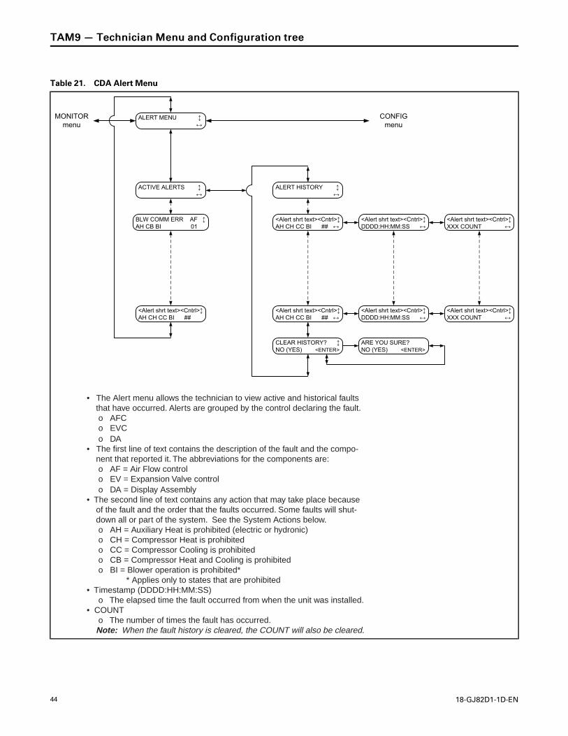
Table 21. CDA Alert Menu
BLW COMM ERR AF ↕AH CB BI 01
CLEAR HISTORY? ↕NO (YES) <ENTER>
ACTIVE ALERTS ↕↔
<Alert shrt text><Cntrl>↕AH CH CC BI ##
ALERT HISTORY ↕↔
<Alert shrt text><Cntrl>↕AH CH CC BI ## ↔
<Alert shrt text><Cntrl>↕DDDD:HH:MM:SS ↔
<Alert shrt text><Cntrl>↕XXX COUNT ↔
<Alert shrt text><Cntrl>↕AH CH CC BI ## ↔
<Alert shrt text><Cntrl>↕DDDD:HH:MM:SS ↔
<Alert shrt text><Cntrl>↕XXX COUNT ↔
ARE YOU SURE?NO (YES) <ENTER>
ALERT MENU ↕↔
CONFIG menu
MONITOR menu
• The Alert menu allows the technician to view active and historical faults that have occurred. Alerts are grouped by the control declaring the fault.
o AFC o EVC o DA• The first line of text contains the description of the fault and the compo-
nent that reported it. The abbreviations for the components are: o AF = Air Flow control o EV = Expansion Valve control o DA = Display Assembly• The second line of text contains any action that may take place because
of the fault and the order that the faults occurred. Some faults will shut-down all or part of the system. See the System Actions below.
o AH = Auxiliary Heat is prohibited (electric or hydronic) o CH = Compressor Heat is prohibited o CC = Compressor Cooling is prohibited o CB = Compressor Heat and Cooling is prohibited o BI = Blower operation is prohibited* * Applies only to states that are prohibited• Timestamp (DDDD:HH:MM:SS) o The elapsed time the fault occurred from when the unit was installed.• COUNT o The number of times the fault has occurred. Note: When the fault history is cleared, the COUNT will also be cleared.
TTAAMM99 —— TTeecchhnniicciiaann MMeennuu aanndd CCoonnffiigguurraattiioonn ttrreeee
18-GJ82D1-1D-EN 45
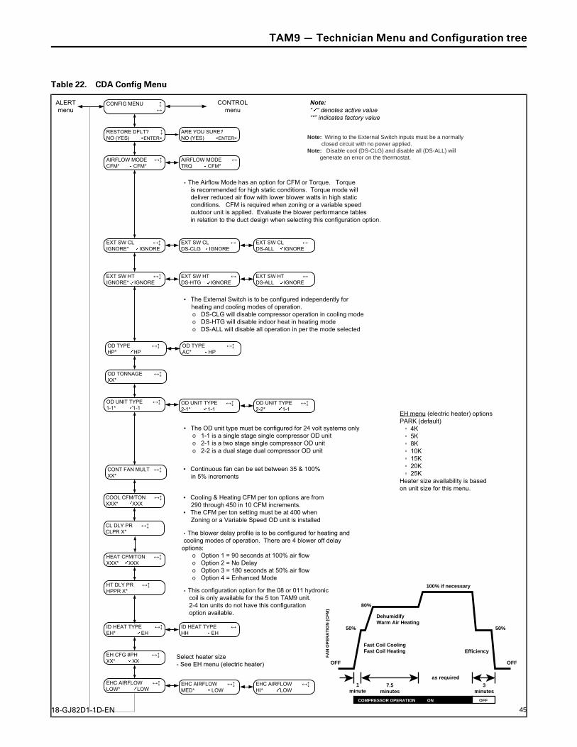
Table 22. CDA Config Menu
CONFIG MENU ↕↔
AIRFLOW MODE ↔↕CFM* CFM*
AIRFLOW MODE ↔TRQ CFM*
COOL CFM/TON ↔↕XXX* XXX
HEAT CFM/TON ↔↕XXX* XXX
EXT SW CL ↔↕IGNORE* IGNORE
EXT SW CL ↔DS-ALL IGNORE
EXT SW CL ↔DS-CLG IGNORE
EXT SW HT ↔↕IGNORE* IGNORE
EXT SW HT ↔DS-ALL IGNORE
EXT SW HT ↔DS-HTG IGNORE
ALERT menu
CONTROL menu
RESTORE DFLT? ↕NO (YES) <ENTER>
ARE YOU SURE?NO (YES) <ENTER>
Note:“ “ denotes active value “*” indicates factory value
ID HEAT TYPE ↔↕EH* EH
ID HEAT TYPE ↔HH EH
EH CFG #PH ↔↕XX* XX
EHC AIRFLOW ↔↕LOW* LOW
EHC AIRFLOW ↔↕MED* LOW
EHC AIRFLOW ↔↕HI* LOW
OD UNIT TYPE ↔↕1-1* 1-1
OD UNIT TYPE ↔↕2-1* 1-1
OD UNIT TYPE ↔↕2-2* 1-1
OD TYPE ↔↕HP* HP
OD TYPE ↔↕AC* HP
OD TONNAGE ↔↕XX*
CONT FAN MULT ↔↕XX*
CL DLY PR ↔↕CLPR X*
HT DLY PR ↔↕HPPR X*
Note: Wiring to the External Switch inputs must be a normally closed circuit with no power applied.Note: Disable cool (DS-CLG) and disable all (DS-ALL) will generate an error on the thermostat.
• Cooling & Heating CFM per ton options are from 290 through 450 in 10 CFM increments.
• The CFM per ton setting must be at 400 when Zoning or a Variable Speed OD unit is installed
• This configuration option for the 08 or 011 hydronic coil is only available for the 5 ton TAM9 unit. 2-4 ton units do not have this configuration option available.
Select heater size - See EH menu (electric heater)
EH menu (electric heater) optionsPARK (default) ◦ 4K ◦ 5K ◦ 8K ◦ 10K ◦ 15K ◦ 20K ◦ 25KHeater size availability is basedon unit size for this menu.
• The OD unit type must be configured for 24 volt systems only o 1-1 is a single stage single compressor OD unit o 2-1 is a two stage single compressor OD unit o 2-2 is a dual stage dual compressor OD unit
• Continuous fan can be set between 35 & 100% in 5% increments
• The External Switch is to be configured independently for heating and cooling modes of operation.
o DS-CLG will disable compressor operation in cooling mode o DS-HTG will disable indoor heat in heating mode o DS-ALL will disable all operation in per the mode selected
• The Airflow Mode has an option for CFM or Torque. Torque is recommended for high static conditions. Torque mode will deliver reduced air flow with lower blower watts in high static conditions. CFM is required when zoning or a variable speed outdoor unit is applied. Evaluate the blower performance tables in relation to the duct design when selecting this configuration option.
• The blower delay profile is to be configured for heating and cooling modes of operation. There are 4 blower off delay
options: o Option 1 = 90 seconds at 100% air flow o Option 2 = No Delay o Option 3 = 180 seconds at 50% air flow o Option 4 = Enhanced Mode
OFF OFF
50%
80%
100% if necessary
50%
DehumidifyWarm Air Heating
Fast Coil CoolingFast Coil Heating Efficiency
7.5minutes
3minutes
1minute
FA
N O
PE
RA
TIO
N (
CF
M)
as required
COMPRESSOR OPERATION ON OFF
TTAAMM99 —— TTeecchhnniicciiaann MMeennuu aanndd CCoonnffiigguurraattiioonn ttrreeee
46 18-GJ82D1-1D-EN
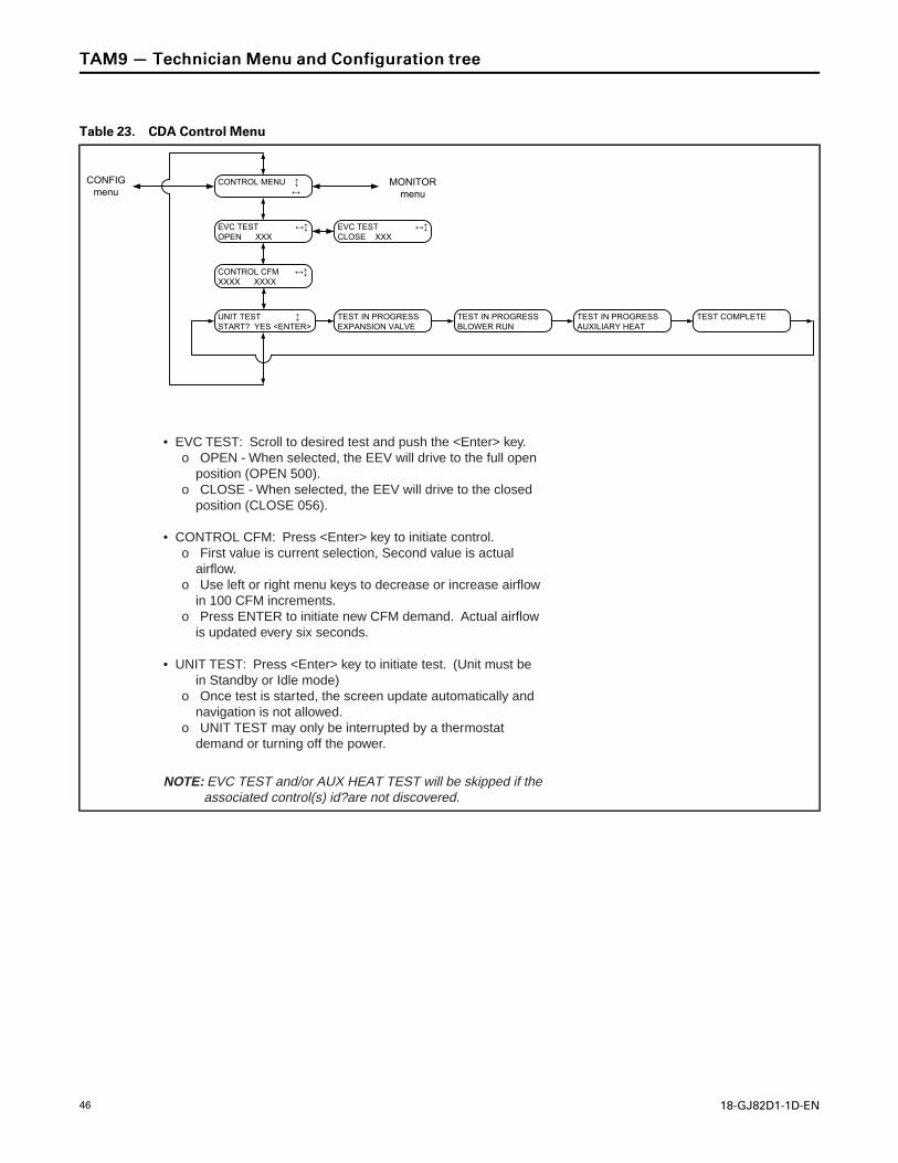
Table 23. CDA Control Menu
CONTROL MENU ↕↔
EVC TEST ↔↕OPEN XXX
EVC TEST ↔↕CLOSE XXX
CONTROL CFM ↔↕XXXX XXXX
UNIT TEST ↕START? YES <ENTER>
CONFIG menu
MONITOR menu
TEST IN PROGRESSEXPANSION VALVE
TEST IN PROGRESSBLOWER RUN
TEST IN PROGRESSAUXILIARY HEAT
TEST COMPLETE
• EVC TEST: Scroll to desired test and push the <Enter> key. o OPEN - When selected, the EEV will drive to the full open
position (OPEN 500). o CLOSE - When selected, the EEV will drive to the closed
position (CLOSE 056).
• CONTROL CFM: Press <Enter> key to initiate control. o First value is current selection, Second value is actual
airflow. o Use left or right menu keys to decrease or increase airflow
in 100 CFM increments. o Press ENTER to initiate new CFM demand. Actual airflow
is updated every six seconds.
NOTE: EVC TEST and/or AUX HEAT TEST will be skipped if theassociated control(s) id?are not discovered.
• UNIT TEST: Press <Enter> key to initiate test. (Unit must be in Standby or Idle mode)
o Once test is started, the screen update automatically and navigation is not allowed.
o UNIT TEST may only be interrupted by a thermostat demand or turning off the power.
TTAAMM99 —— TTeecchhnniicciiaann MMeennuu aanndd CCoonnffiigguurraattiioonn ttrreeee
18-GJ82D1-1D-EN 47
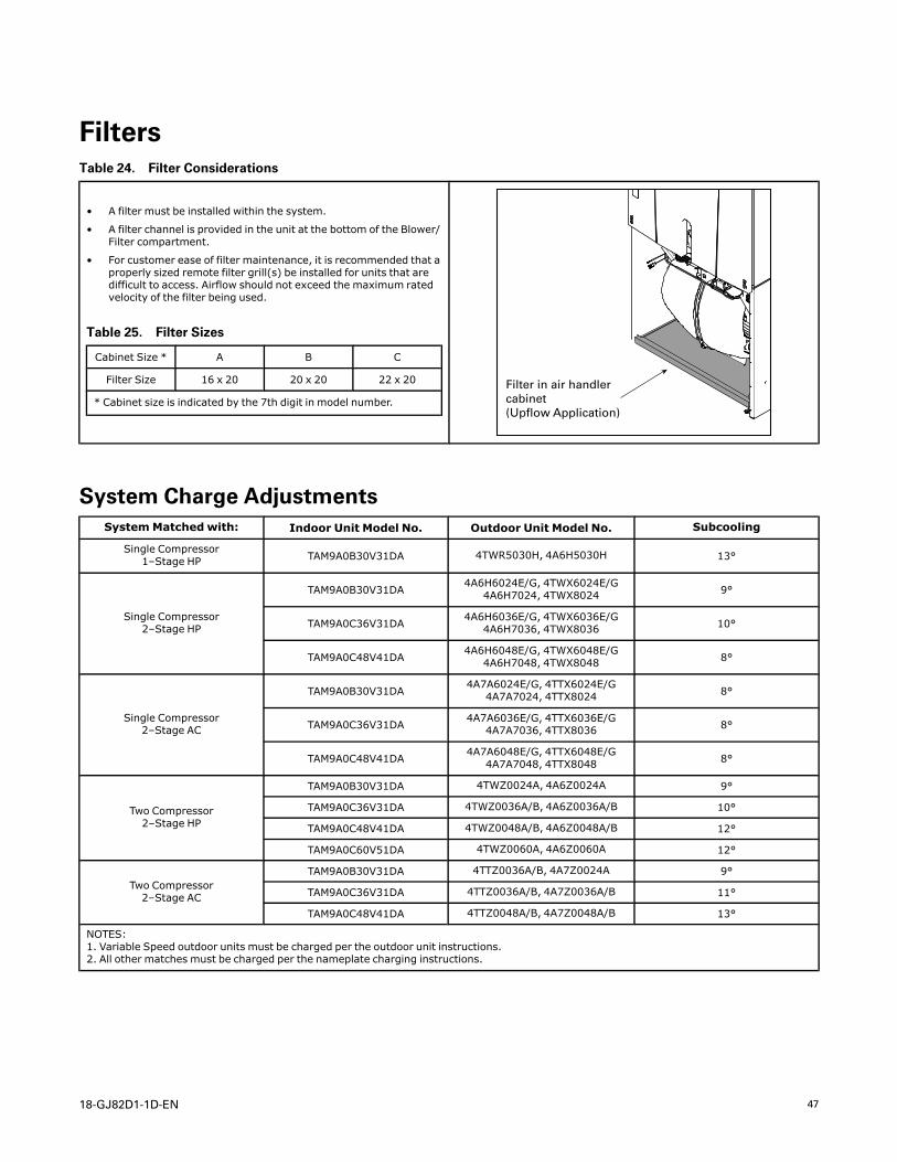
FiltersTable 24. Filter Considerations
• A filter must be installed within the system.
• A filter channel is provided in the unit at the bottom of the Blower/Filter compartment.
• For customer ease of filter maintenance, it is recommended that aproperly sized remote filter grill(s) be installed for units that aredifficult to access. Airflow should not exceed the maximum ratedvelocity of the filter being used.
Table 25. Filter Sizes
Cabinet Size * A B C
Filter Size 16 x 20 20 x 20 22 x 20
* Cabinet size is indicated by the 7th digit in model number.
Filter in air handler cabinet (Upflow Application)
System Charge AdjustmentsSystemMatched with: Indoor Unit Model No. Outdoor Unit Model No. Subcooling
Single Compressor1–Stage HP TAM9A0B30V31DA 4TWR5030H, 4A6H5030H 13°
Single Compressor2–Stage HP
TAM9A0B30V31DA4A6H6024E/G, 4TWX6024E/G
4A6H7024, 4TWX8024 9°
TAM9A0C36V31DA 4A6H6036E/G, 4TWX6036E/G4A6H7036, 4TWX8036 10°
TAM9A0C48V41DA4A6H6048E/G, 4TWX6048E/G
4A6H7048, 4TWX8048 8°
Single Compressor2–Stage AC
TAM9A0B30V31DA4A7A6024E/G, 4TTX6024E/G
4A7A7024, 4TTX8024 8°
TAM9A0C36V31DA 4A7A6036E/G, 4TTX6036E/G4A7A7036, 4TTX8036 8°
TAM9A0C48V41DA4A7A6048E/G, 4TTX6048E/G
4A7A7048, 4TTX8048 8°
Two Compressor2–Stage HP
TAM9A0B30V31DA 4TWZ0024A, 4A6Z0024A 9°
TAM9A0C36V31DA 4TWZ0036A/B, 4A6Z0036A/B 10°
TAM9A0C48V41DA 4TWZ0048A/B, 4A6Z0048A/B 12°
TAM9A0C60V51DA 4TWZ0060A, 4A6Z0060A 12°
Two Compressor2–Stage AC
TAM9A0B30V31DA 4TTZ0036A/B, 4A7Z0024A 9°
TAM9A0C36V31DA 4TTZ0036A/B, 4A7Z0036A/B 11°
TAM9A0C48V41DA 4TTZ0048A/B, 4A7Z0048A/B 13°
NOTES:1. Variable Speed outdoor units must be charged per the outdoor unit instructions.2. All other matches must be charged per the nameplate charging instructions.
48 18-GJ82D1-1D-EN
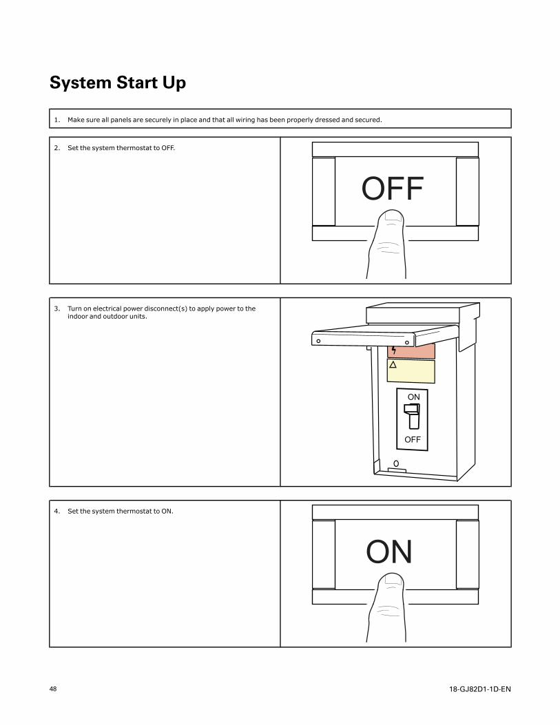
System Start Up
1. Make sure all panels are securely in place and that all wiring has been properly dressed and secured.
2. Set the system thermostat to OFF.
OFF
3. Turn on electrical power disconnect(s) to apply power to theindoor and outdoor units.
ON
OFF
4. Set the system thermostat to ON.
ON
18-GJ82D1-1D-EN 49
TAM9 Sequence of OperationAbbreviations• AFC = Airflow Control• EVC = Expansion Valve Control• EEV = Electronic Expansion Valve
NNoottee:: When used with variable speed outdoor units,indoor airflow and EEV starting position iscontrolled by the outdoor unit IVSC through thedata line between the units.
NNoottee:: Use variable speed outdoor Sequence ofOperation in conjunction with the TAM9Sequence of Operation.
The installing and servicing technician should have anunderstanding of the sequence of operation to be ableto properly setup and diagnose functions of the airhandler.
SSeeee uunniitt,, eelleeccttrriicc hheeaatt,, aanndd ffiieelldd wwiirriinngg ddiiaaggrraammssffoorr aaddddiittiioonnaall iinnffoorrmmaattiioonn..
CCoonnttiinnuuoouuss FFaann
IImmppoorrttaanntt:: If the indoor air exceeds 60% relativehumidity or simply feels uncomfortablyhumid, it is recommended that the indoorfan only be used in the AUTO mode.
1. When a fan request is received from thethermostat, the AFC sends a command to the serialcommunicating blower motor to run. Airflow can beadjusted through the thermostat.
2. Humidity Control – When enabled at thethermostat, this feature will disable any blower offdelays and disable continuous fan mode when thehumidity is above the dehumidification setpoint.This will help prevent coil condensation from beingevaporated back into the air stream.
CCoooolliinngg MMooddee
1. When a request for 1st stage cooling is received,the AFC sends a command to the serialcommunicating blower motor to run at 1st stagecooling airflow. (Delay profiles from the thermostatmay change blower motor timing and actual airflowdemand)
2. The EVC will receive input from the twotemperature sensors and start to control 1st stagesuperheat. .
3. When a request for 2nd stage cooling is received,the AFC sends a command to the serialcommunicating blower motor to run at 100 %cooling airflow.
4. The EVC will now control superheat for 2nd stage.5. When a request for cooling is removed, the AFC
will turn off the blower motor after any userselected fan-off delays have expired.
NNoottee:: Delay profiles from the thermostat may changeblower motor timing and actual airflow demand.
HHeeaatt ppuummpp ((ccoommpprreessssoorr oonnllyy))
1. When a request for 1st stage heat is received, theAFC sends a command to the serial communicatingblower motor to run at 1st stage heating airflow.
2. Humidifier contacts close on demand fromthermostat.
3. The EVC will drive the EEV to the heating positionand refrigerant will flow in the reverse cycle.
4. When a request for 2nd stage mechanical heat isreceived, the AFC sends a command to the serialcommunicating blower motor to run at 100 %heating airflow.
5. When a request for heat pump is removed, the AFCwill turn off the blower motor after any userselected fan-off delays have expired.
NNoottee:: Delay profiles from the thermostat may changeblower motor timing and actual airflow demand.
EElleeccttrriicc HHeeaatt
1. When a request for electric heat is received, the AFCwill energize the on board 24 volt relays per theamount of heat requested from the thermostat andthe size of the heater installed.
2. The AFC sends a command to the serialcommunicating blower motor to run proper airflowand close the blower interlock relay on the EHC.
HHyyddrroonniicc HHeeaatt
1. When a request for hydronic heat is received, theAFC will energize the on board W1 relay.
2. The AFC sends a command to the serialcommunicating blower motor to run at therequested CFM.
DDeeffrroosstt
1. The OD unit will initiate defrost and send amessage to the AFC.
2. The AFC will communicate to the EVC that the OD isin defrost and the EVC will start to control thecorrect superheat.
3. Electric or hydronic heat will be energized to helptemper the air.
FFrreeeezzee PPrrootteeccttiioonn
1. The EVC control has the ability to sense when theindoor coil is beginning to ice. If this event shouldoccur, the AFC will send a message to de-energizethe OD unit.
2. The indoor blower motor will continue running toaid in defrosting the coil.
50 18-GJ82D1-1D-EN
3. After 5 minutes, the OD will be turned back on.(*CONT900 and the 1st release of the *ZONE950will disable the indoor blower motor and OD unitfor 30 minutes)
UUnniitt TTeesstt MMooddee
Unit Test Mode will exit if any demand is given to theunit.
To enter Unit Test Mode:
1. Set System Switch on comfort control to Off.2. Scroll to the Control Menu on the Display
Assembly.3. Scroll down to the Unit Test selection and push the
"Enter" button.
SSeeqquueennccee ooff UUnniitt TTeesstt MMooddee ((OODD uunniitt iiss nnootteenneerrggiizzeedd dduurriinngg tthhee UUnniitt TTeesstt MMooddee))
1. EVC drives the EEV motor to the 1st stage positionfor 5 seconds.
2. EVC drives the EEV motor to the 2nd stage positionfor 5 seconds.
3. AFC energizes the blower at 50% and thencontinues to ramp until it reaches 100% coolingairflow.
4. Humidifier contacts close when the blower starts.
5. AFC energizes the W relays in 10 second intervals.The blower remains at 100% air flow.
6. All relays de-energize and the blower shuts off fiveseconds after the last bank of heat is energized.
NNoottee:: If an error occurs during the Unit Test Mode, theFault LED will flash a code and continue the test.
TTAAMM99 SSeeqquueennccee ooff OOppeerraattiioonn
18-GJ82D1-1D-EN 51
Fault Reporting
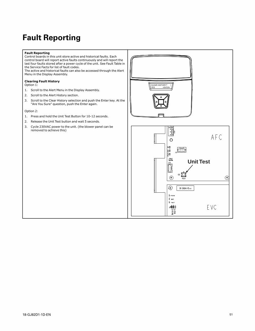
Fault ReportingControl boards in this unit store active and historical faults. Eachcontrol board will report active faults continuously and will report thelast four faults stored after a power cycle of the unit. See Fault Table inthe Service Facts for list of fault codes.The active and historical faults can also be accessed through the AlertMenu in the Display Assembly.
Clearing Fault HistoryOption 1:
1. Scroll to the Alert Menu in the Display Assembly.
2. Scroll to the Alert History section.
3. Scroll to the Clear History selection and push the Enter key. At the"Are You Sure" question, push the Enter again.
Option 2:
1. Press and hold the Unit Test Button for 10-12 seconds.
2. Release the Unit Test button and wait 5 seconds.
3. Cycle 230VAC power to the unit. (the blower panel can beremoved to achieve this)
CLEAR HISTORY? ↕YES <ENTER>
Unit Test
52 18-GJ82D1-1D-EN
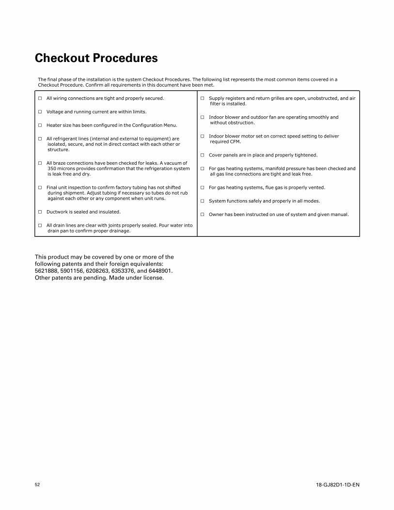
Checkout Procedures
The final phase of the installation is the system Checkout Procedures. The following list represents the most common items covered in aCheckout Procedure. Confirm all requirements in this document have been met.
☐ All wiring connections are tight and properly secured.
☐ Voltage and running current are within limits.
☐ Heater size has been configured in the Configuration Menu.
☐ All refrigerant lines (internal and external to equipment) areisolated, secure, and not in direct contact with each other orstructure.
☐ All braze connections have been checked for leaks. A vacuum of350 microns provides confirmation that the refrigeration systemis leak free and dry.
☐ Final unit inspection to confirm factory tubing has not shiftedduring shipment. Adjust tubing if necessary so tubes do not rubagainst each other or any component when unit runs.
☐ Ductwork is sealed and insulated.
☐ All drain lines are clear with joints properly sealed. Pour water intodrain pan to confirm proper drainage.
☐ Supply registers and return grilles are open, unobstructed, and airfilter is installed.
☐ Indoor blower and outdoor fan are operating smoothly andwithout obstruction.
☐ Indoor blower motor set on correct speed setting to deliverrequired CFM.
☐ Cover panels are in place and properly tightened.
☐ For gas heating systems, manifold pressure has been checked andall gas line connections are tight and leak free.
☐ For gas heating systems, flue gas is properly vented.
☐ System functions safely and properly in all modes.
☐ Owner has been instructed on use of system and given manual.
This product may be covered by one or more of thefollowing patents and their foreign equivalents:5621888, 5901156, 6208263, 6353376, and 6448901.Other patents are pending. Made under license.
18-GJ82D1-1D-EN 53
NNootteess
54 18-GJ82D1-1D-EN
NNootteess

18-GJ82D1-1D-EN 55
NNootteess
Ingersoll Rand (NYSE: IR) advances the quality of life by creating comfortable, sustainable and efficientenvironments. Our people and our family of brands — including Club Car®, Ingersoll Rand®, Thermo King® andTrane® —work together to enhance the quality and comfort of air in homes and buildings; transport and protectfood and perishables; and increase industrial productivity and efficiency. We are a global business committed to aworld of sustainable progress and enduring results.
ingersollrand.com
Ingersoll Rand has a policy of continuous product and product data improvements and reserves the right to change design and specificationswithout notice.We are committed to using environmentally conscious print practices.
18-GJ82D1-1D-EN 14 Sep 2018
Supersedes 18-GJ82D1-1C-EN (October 2017) ©2016 Ingersoll Rand