001_common rail diesel 1
DESCRIPTION
common rail noteTRANSCRIPT
2.8 ltr. TDI Engine with Common Rail Injection
Design and Function
Self-Study Programme 266
Service.

2
NEW ImportantNote
Please always refer to the relevant Service Literature
for all inspection, adjustment and repair instructions.
This Self-Study Programme explains the
design and function of new developments!
The contents are not updated.
Common Rail Injection System
Present and future requirements regarding modern drive systems are mainly dictated by ecological awareness and economic efficiency.
But these requirements are becoming more and more important due to the constantly growing number of diesel vehicles.
Mechanically regulated injection systems used in the past no longer meet the full requirements for low consumption, lower exhaust emissions and smooth engine running. Now there are additional requirements such as very high injection pressures, exact injection cycles and high-precision dosing of the injected fuel.
These requirements are met by the common rail injection system which has now been fitted to the 2.8 ltr. TDI engine in the VW LT2.
This Self-Study Programme describes the system and the necessary changes to the basic engine.
266_059
3
Table of Contents
Introduction . . . . . . . . . . . . . . . . . . . . . . . . . . . . . . . . . . 4
Engine mechanicals . . . . . . . . . . . . . . . . . . . . . . . . . . . . 6
Common rail injection system . . . . . . . . . . . . . . . . . . . 15
Engine management. . . . . . . . . . . . . . . . . . . . . . . . . . .32
Auxiliary functions . . . . . . . . . . . . . . . . . . . . . . . . . . . .50
Test your knowledge. . . . . . . . . . . . . . . . . . . . . . . . . . .54
4
Introduction
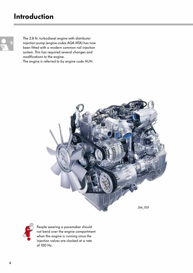
The 2.8 ltr. turbodiesel engine with distributor injection pump (engine codes AGK/ATA) has now been fitted with a modern common rail injection system. This has required several changes and modifications to the engine. The engine is referred to by engine code AUH.
266_033
People wearing a pacemaker should not bend over the engine compartment when the engine is running since the injection valves are clocked at a rate of 100 Hz.
5
1000 2000 3000 4000
100
200
300
400
500
25
50
75
100
125
0
Engine speed [rpm]
Torq
ue [
Nm
]
Pow
er o
utpu
t [kW
]
266_003
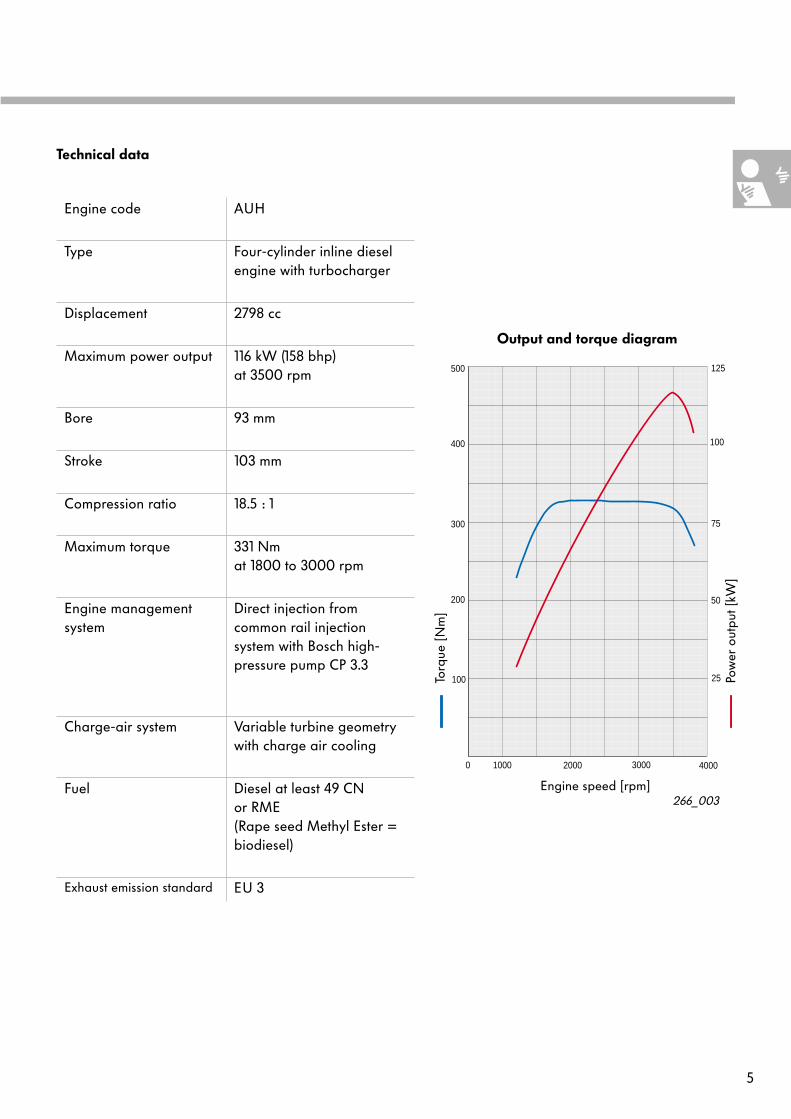
Output and torque diagram
Engine code AUH
Type Four-cylinder inline diesel engine with turbocharger
Displacement 2798 cc
Maximum power output 116 kW (158 bhp) at 3500 rpm
Bore 93 mm
Stroke 103 mm
Compression ratio 18.5 : 1
Maximum torque 331 Nm at 1800 to 3000 rpm
Engine management system
Direct injection from common rail injectionsystem with Bosch high-pressure pump CP 3.3
Charge-air system Variable turbine geometry with charge air cooling
Fuel Diesel at least 49 CNor RME (Rape seed Methyl Ester = biodiesel)
Exhaust emission standard
EU 3
Technical data
6
Engine mechanicals
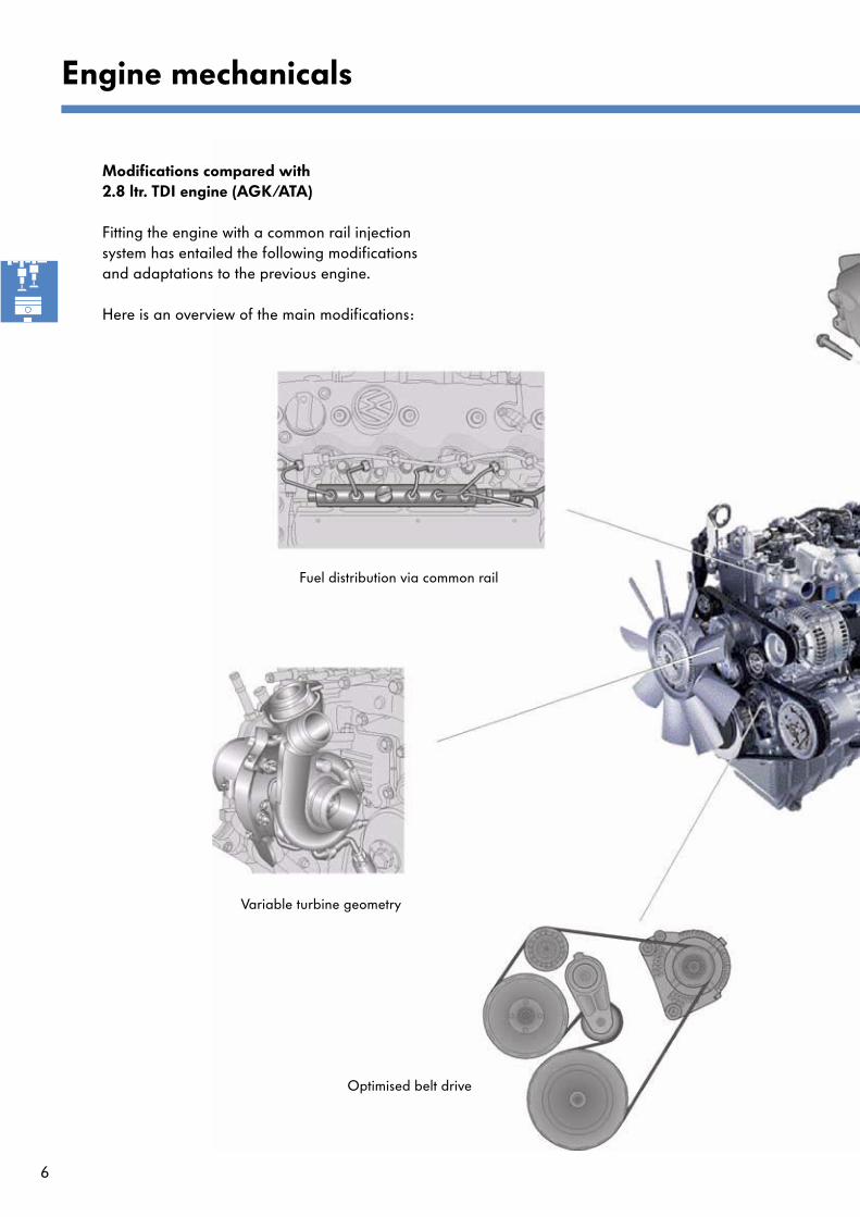
Fuel distribution via common rail
Variable turbine geometry
Optimised belt drive
Modifications compared with 2.8 ltr. TDI engine (AGK/ATA)
Fitting the engine with a common rail injection system has entailed the following modifications and adaptations to the previous engine.
Here is an overview of the main modifications:
7
266_087
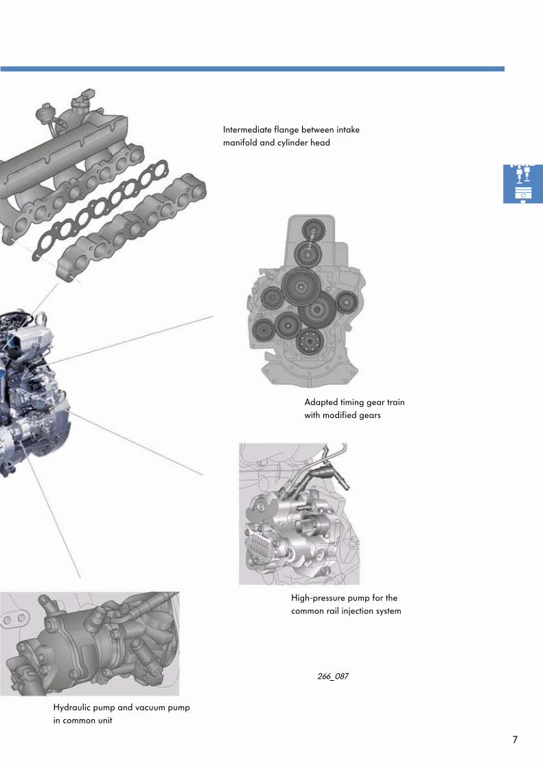
Hydraulic pump and vacuum pump in common unit
Adapted timing gear train with modified gears
Intermediate flange between intake manifold and cylinder head
High-pressure pump for the common rail injection system
8
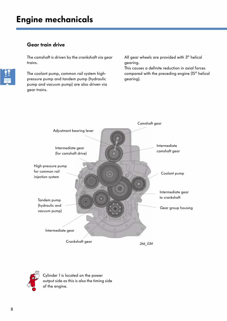
Gear train drive
The camshaft is driven by the crankshaft via gear trains.
The coolant pump, common rail system high-pressure pump and tandem pump (hydraulic pump and vacuum pump) are also driven via gear trains.
Cylinder 1 is located on the power output side as this is also the timing side of the engine.
All gear wheels are provided with 3
o
helical gearing. This causes a definite reduction in axial forces compared with the preceding engine (15
o
helical gearing).
266_034
Engine mechanicals
Adjustment bearing lever
Camshaft gear
Intermediate camshaft gear
Coolant pump
Intermediate gear to crankshaft
Gear group housing
High-pressure pump for common railinjection system
Intermediate gear (for camshaft drive)
Tandem pump (hydraulic and vacuum pump)
Intermediate gear
Crankshaft gear
9
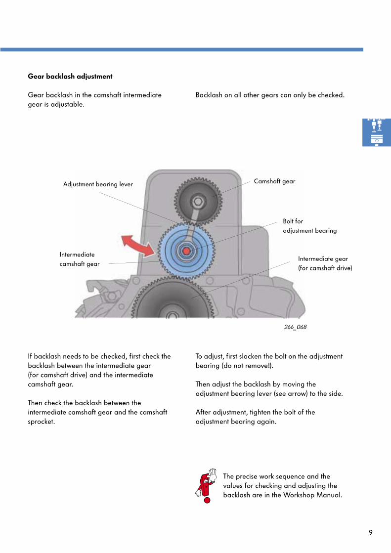
Gear backlash adjustment
Gear backlash in the camshaft intermediate gear is adjustable.
Backlash on all other gears can only be checked.
If backlash needs to be checked, first check the backlash between the intermediate gear (for camshaft drive) and the intermediate camshaft gear.
Then check the backlash between the intermediate camshaft gear and the camshaft sprocket.
To adjust, first slacken the bolt on the adjustment bearing (do not remove!).
Then adjust the backlash by moving the adjustment bearing lever (see arrow) to the side.
After adjustment, tighten the bolt of the adjustment bearing again.
266_068
Camshaft gear
Intermediate camshaft gear
Bolt foradjustment bearing
Adjustment bearing lever
Intermediate gear (for camshaft drive)
The precise work sequence and the values for checking and adjusting the backlash are in the Workshop Manual.
10
Engine mechanicals
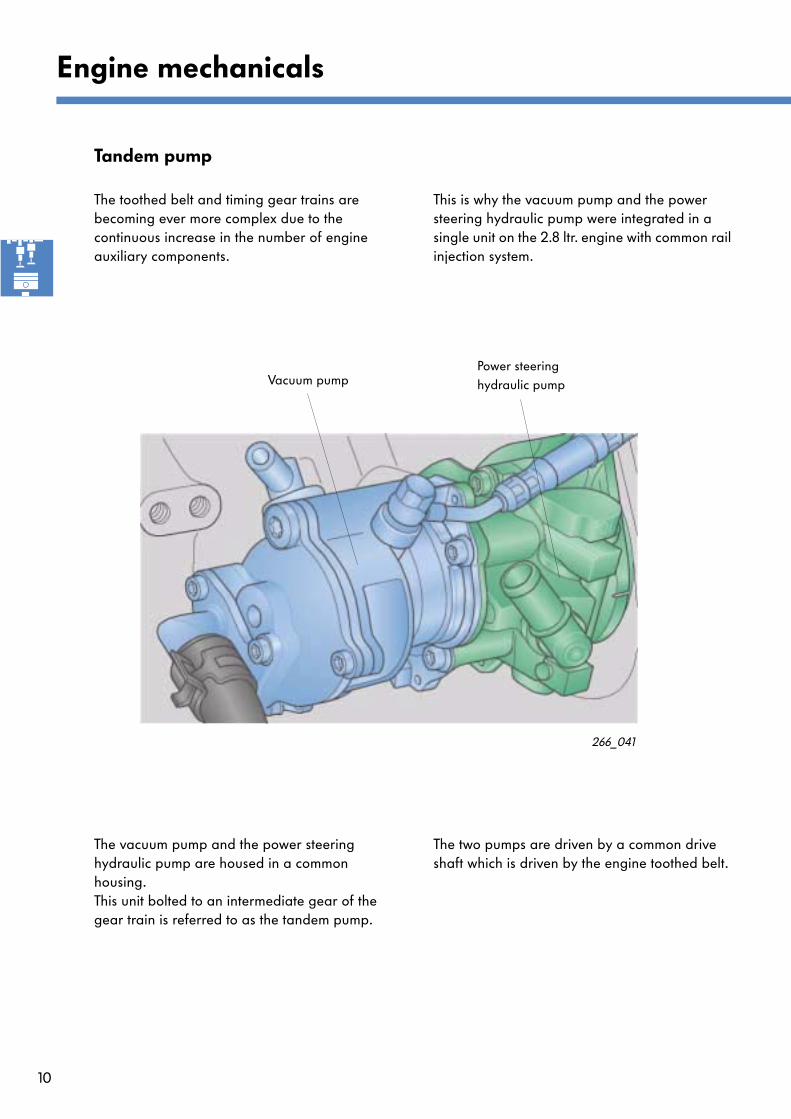
Tandem pump
The toothed belt and timing gear trains are becoming ever more complex due to the continuous increase in the number of engine auxiliary components.
The vacuum pump and the power steering hydraulic pump are housed in a common housing.This unit bolted to an intermediate gear of the gear train is referred to as the tandem pump.
The two pumps are driven by a common drive shaft which is driven by the engine toothed belt.
This is why the vacuum pump and the power steering hydraulic pump were integrated in a single unit on the 2.8 ltr. engine with common rail injection system.
Vacuum pumpPower steering hydraulic pump
266_041
11
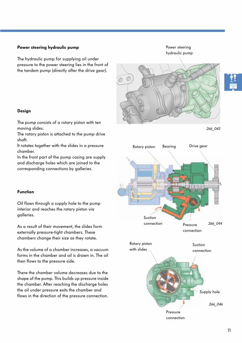
Power steering hydraulic pump
The hydraulic pump for supplying oil under pressure to the power steering lies in the front of the tandem pump (directly after the drive gear).
Design
The pump consists of a rotary piston with ten moving slides. The rotary piston is attached to the pump drive shaft. It rotates together with the slides in a pressure chamber. In the front part of the pump casing are supply and discharge holes which are joined to the corresponding connections by galleries.
Function
Oil flows through a supply hole to the pump interior and reaches the rotary piston via galleries.
As a result of their movement, the slides form externally pressure-tight chambers. These chambers change their size as they rotate.
As the volume of a chamber increases, a vacuum forms in the chamber and oil is drawn in. The oil then flows to the pressure side.
There the chamber volume decreases due to the shape of the pump. This builds up pressure inside the chamber. After reaching the discharge holes the oil under pressure exits the chamber and flows in the direction of the pressure connection.
266_043
266_044
266_046
Rotary piston Bearing Drive gear
Suction connection Pressure
connection
Pressure connection
Suction connection
Rotary piston with slides
Supply hole
Power steering hydraulic pump

12
Vacuum pump
The rear part of the tandem pump is the vacuum pump.It generates the vacuum for the brake servo and engine control.
Design
The vacuum pump comprises an offset rotor and a blade. The blade is made of plastic and is mounted in a movable bearing. The pump shaft is lubricated by the engine oil circuit via a pressure oil connection.
Function
The turning motion of the rotor and the pushing movement of the blade create two chambers of different volume. When one chamber increases in size, its volume becomes larger - the space is filled with air.
As the rotor continues to move, the chamber is closed off by the blade and the space becomes smaller again. The intake air is compressed in this way. The air is expelled through a valve into the crankcase. At the same time, a new chamber is formed around the vacuum connection.
Lubricating oil that is no longer required is blown out together with the air into the crankcase.
Engine mechanicals
266_042
266_045
Vacuum connection
Lubricating oil connection
Rotor with blade
Valve
Exit air connection(air/oil mixture)
Rotor
BladeLubricating oilconnection
Vacuumconnection
Vacuum pump
Chambers 1 + 2
266_047
13
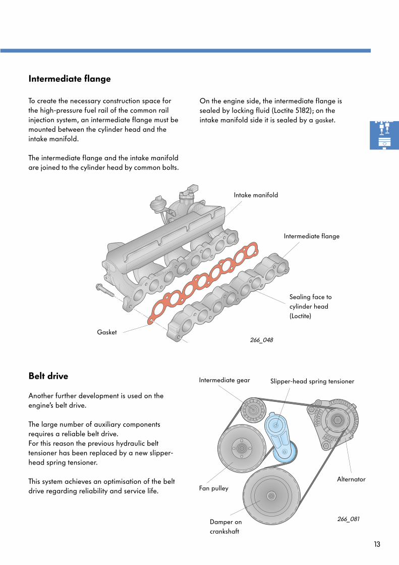
Intermediate flange
To create the necessary construction space for the high-pressure fuel rail of the common rail injection system, an intermediate flange must be mounted between the cylinder head and the intake manifold.
The intermediate flange and the intake manifold are joined to the cylinder head by common bolts.
266_048
Intake manifold
Gasket
Intermediate flange
Sealing face to cylinder head(Loctite)
On the engine side, the intermediate flange is sealed by locking fluid (Loctite 5182); on the intake manifold side it is sealed by a
gasket
.
Belt drive
Another further development is used on the engine’s belt drive.
The large number of auxiliary components requires a reliable belt drive.For this reason the previous hydraulic belt tensioner has been replaced by a new slipper-head spring tensioner.
This system achieves an optimisation of the belt drive regarding reliability and service life.
266_081
Intermediate gear Slipper-head spring tensioner
AlternatorFan pulley
Damper on crankshaft
14
Engine mechanicals
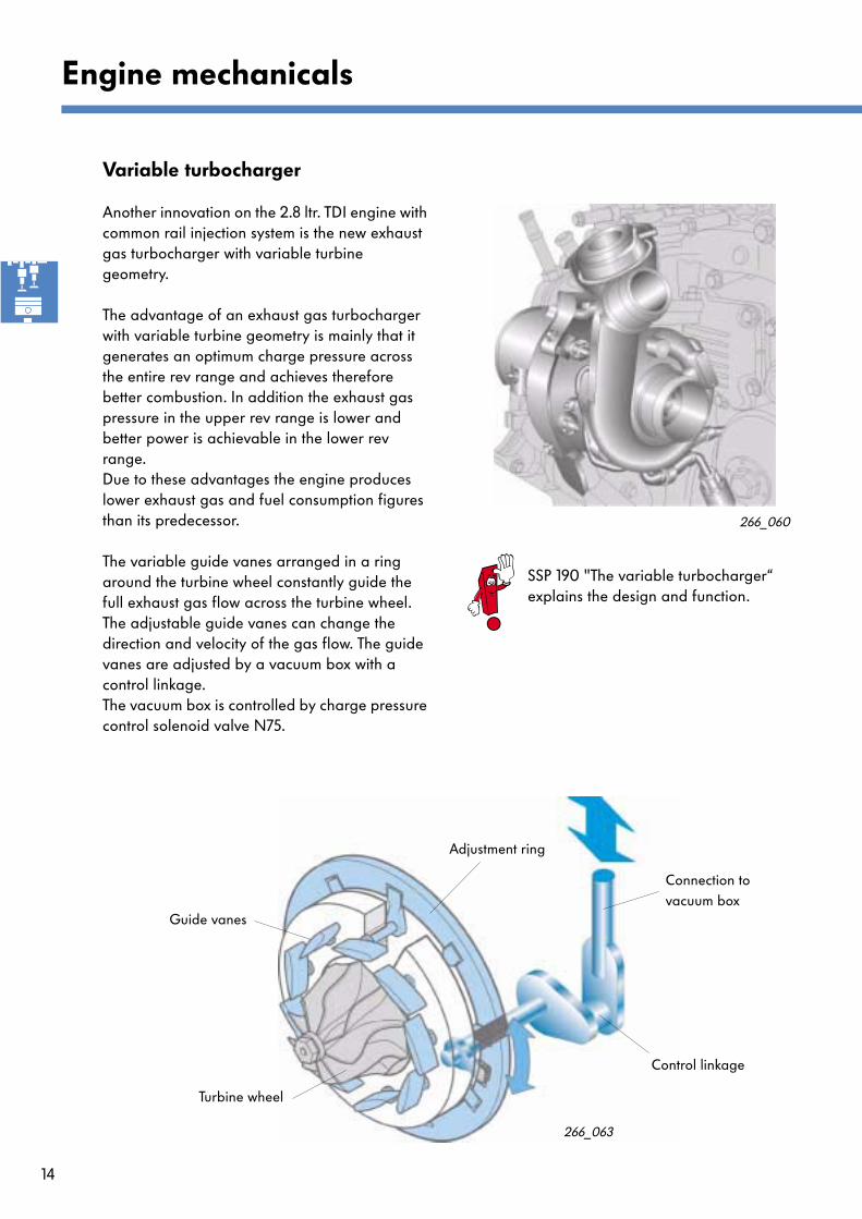
Variable turbocharger
Another innovation on the 2.8 ltr. TDI engine with common rail injection system is the new exhaust gas turbocharger with variable turbine geometry.
The advantage of an exhaust gas turbocharger with variable turbine geometry is mainly that it generates an optimum charge pressure across the entire rev range and achieves therefore better combustion. In addition the exhaust gas pressure in the upper rev range is lower and better power is achievable in the lower rev range. Due to these advantages the engine produces lower exhaust gas and fuel consumption figures than its predecessor.
The variable guide vanes arranged in a ring around the turbine wheel constantly guide the full exhaust gas flow across the turbine wheel. The adjustable guide vanes can change the direction and velocity of the gas flow. The guide vanes are adjusted by a vacuum box with a control linkage. The vacuum box is controlled by charge pressure control solenoid valve N75.
SSP 190 "The variable turbocharger“ explains the design and function.
266_063
266_060
Connection to vacuum box
Control linkage
Turbine wheel
Guide vanes
Adjustment ring
15
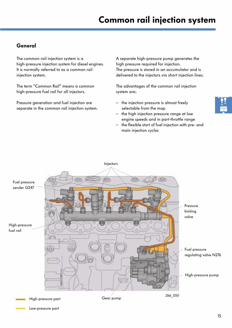
General
The common rail injection system is a high-pressure injection system for diesel engines. It is normally referred to as a common rail injection system.
The term "Common Rail" means a common high-pressure fuel rail for all injectors.
Pressure generation and fuel injection are separate in the common rail injection system.
Common rail injection system
A separate high-pressure pump generates the high pressure required for injection. The pressure is stored in an accumulator and is delivered to the injectors via short injection lines.
The advantages of the common rail injection system are:
– the injection pressure is almost freely selectable from the map
– the high injection pressure range at low engine speeds and in part-throttle range
– the flexible start of fuel injection with pre- and main injection cycles
266_050
Injectors
Fuel pressure sender G247
High-pressure fuel rail
Pressurelimitingvalve
Fuel pressure regulating valve N276
High-pressure pump
Gear pumpHigh-pressure part
Low-pressure part

16
Fuel system
The fuel delivery system is divided into two parts:
– the low-pressure part comprising the fuel pump in the fuel tank, the compensating fuel reservoir, the fuel filter and the gear pump and ...
Common rail injection system
High-pressure pump
Fuel filter
Compensating fuel reservoir
Fuel tank
Gear pump
Fuel pump
Supply line
Return line
Fuel pressure regulating valve N276
Non-returnvalve
Fuelfilter heater
– the high-pressure partcomprising the high-pressure pump, the high- pressure fuel rail, the injectors and the pressure limiting valve.
High-pressure part
Low-pressure part
17
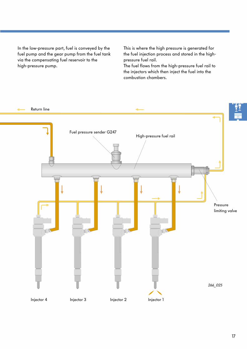
266_025
Injector 4 Injector 3 Injector 2 Injector 1
Pressure limiting valve
Fuel pressure sender G247High-pressure fuel rail
Return line
This is where the high pressure is generated for the fuel injection process and stored in the high- pressure fuel rail.The fuel flows from the high-pressure fuel rail to the injectors which then inject the fuel into the combustion chambers.
In the low-pressure part, fuel is conveyed by the fuel pump and the gear pump from the fuel tank via the compensating fuel reservoir to the high-pressure pump.
18
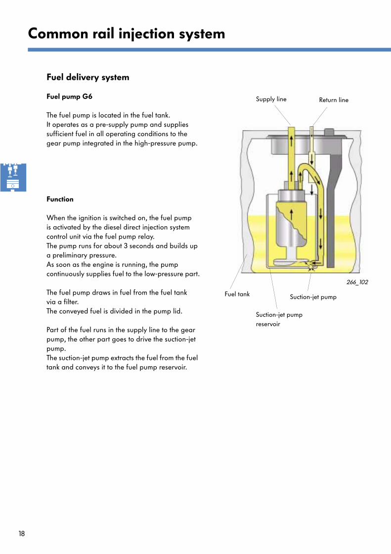
Fuel delivery system
Fuel pump G6
The fuel pump is located in the fuel tank.It operates as a pre-supply pump and supplies sufficient fuel in all operating conditions to the gear pump integrated in the high-pressure pump.
Function
When the ignition is switched on, the fuel pump is activated by the diesel direct injection system control unit via the fuel pump relay.The pump runs for about 3 seconds and builds up a preliminary pressure.As soon as the engine is running, the pump continuously supplies fuel to the low-pressure part.
The fuel pump draws in fuel from the fuel tank via a filter. The conveyed fuel is divided in the pump lid.
Part of the fuel runs in the supply line to the gear pump, the other part goes to drive the suction-jet pump. The suction-jet pump extracts the fuel from the fuel tank and conveys it to the fuel pump reservoir.
Common rail injection system
266_102
Fuel tank
Supply line Return line
Suction-jet pumpreservoir
Suction-jet pump
19
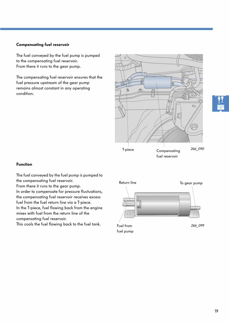
Compensating fuel reservoir
The fuel conveyed by the fuel pump is pumped to the compensating fuel reservoir. From there it runs to the gear pump.
The compensating fuel reservoir ensures that the fuel pressure upstream of the gear pump remains almost constant in any operating condition.
Function
The fuel conveyed by the fuel pump is pumped to the compensating fuel reservoir.From there it runs to the gear pump.In order to compensate for pressure fluctuations, the compensating fuel reservoir receives excess fuel from the fuel return line via a T-piece.In the T-piece, fuel flowing back from the engine mixes with fuel from the return line of the compensating fuel reservoir.This cools the fuel flowing back to the fuel tank.
266_099
266_090
Compensatingfuel reservoir
T-piece
Fuel fromfuel pump
Return line To gear pump
20
31
J686
S
Z57
30
15
31
30
15
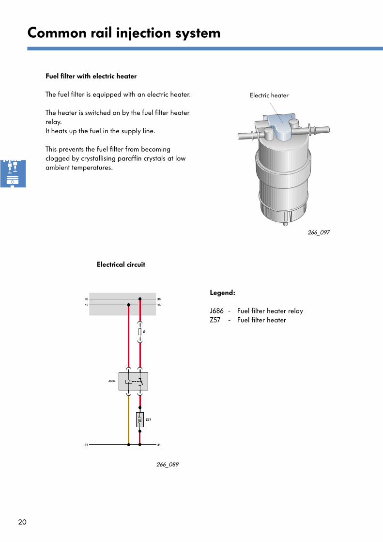
Fuel filter with electric heater
The fuel filter is equipped with an electric heater.
The heater is switched on by the fuel filter heater relay.It heats up the fuel in the supply line.
This prevents the fuel filter from becoming clogged by crystallising paraffin crystals at low ambient temperatures.
Common rail injection system
Electrical circuit
266_089
266_097
Electric heater
Legend:
J686 - Fuel filter heater relayZ57 - Fuel filter heater

21
Gear pump
The gear pump is a purely mechanical pre-supply pump.It increases the fuel pressure provided by the fuel pump G6 to ensure supply of the high-pressure pump with fuel in all operating conditions.The gear pump is located directly on the high-pressure pump.Both pumps are driven by a common shaft.
Design
Two gears rotating in opposite directions are located in the gear pump housing. One gear is driven by the input shaft.
Function
When the gears rotate, fuel is entrained between the gear trains and is conveyed along the pump inner walls to the pressure side. From there, the fuel continues to the high-pressure pump housing. The engaging teeth of the two gears prevent fuel from flowing back.
Pump housing
Drive gear
266_007
266_057
Pressure side
Suction side
Gear pump High-pressure pump

22
High-pressure part
High-pressure pump
Its function is to generate the fuel pressure required for injection at high pressure. The high pressure is produced by three pump pistons arranged in a star at an angle of 120
o
.
The high-pressure pump is bolted to the gear train intermediate flange and is driven by the crankshaft via intermediate gears.
The gear pump and the fuel pressure regulating valve are also located on the high-pressure pump.
Pump piston
Lifting plate
Fuel pressure regulating valve N276
Pump housing
Coil spring
Drive shaft
266_008
Common rail injection system
266_051
Return flow connection
High-pressure connection
Supply connection
Slip ring seal
High-pressure pump Fuel pressure regulating valve
Gear pump
23
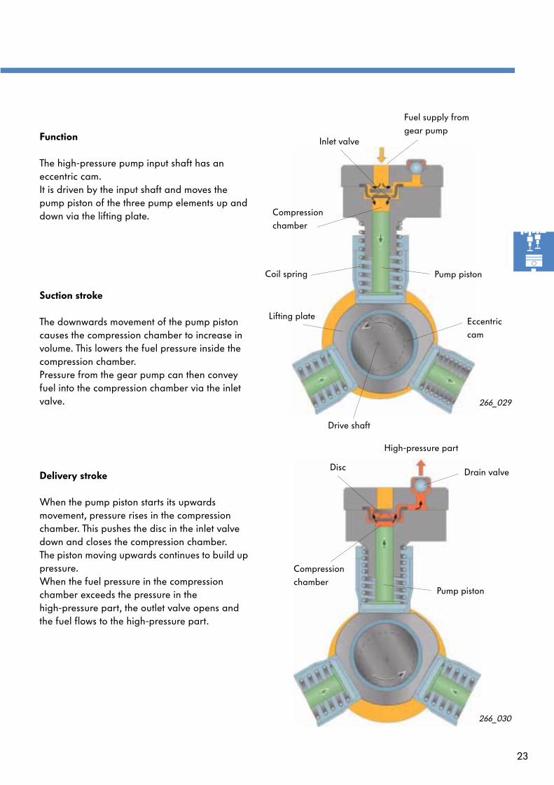
Function
The high-pressure pump input shaft has an eccentric cam.It is driven by the input shaft and moves the pump piston of the three pump elements up and down via the lifting plate.
Suction stroke
The downwards movement of the pump piston causes the compression chamber to increase in volume. This lowers the fuel pressure inside the compression chamber.Pressure from the gear pump can then convey fuel into the compression chamber via the inlet valve.
266_029
Pump piston
Drive shaft
Coil spring
Inlet valve
Fuel supply from gear pump
Compression chamber
Eccentric cam
Lifting plate
Delivery stroke
When the pump piston starts its upwards movement, pressure rises in the compression chamber. This pushes the disc in the inlet valve down and closes the compression chamber.The piston moving upwards continues to build up pressure. When the fuel pressure in the compression chamber exceeds the pressure in the high-pressure part, the outlet valve opens and the fuel flows to the high-pressure part.
266_030
Drain valveDisc
Pump piston
Compression chamber
High-pressure part
24
Common rail injection system
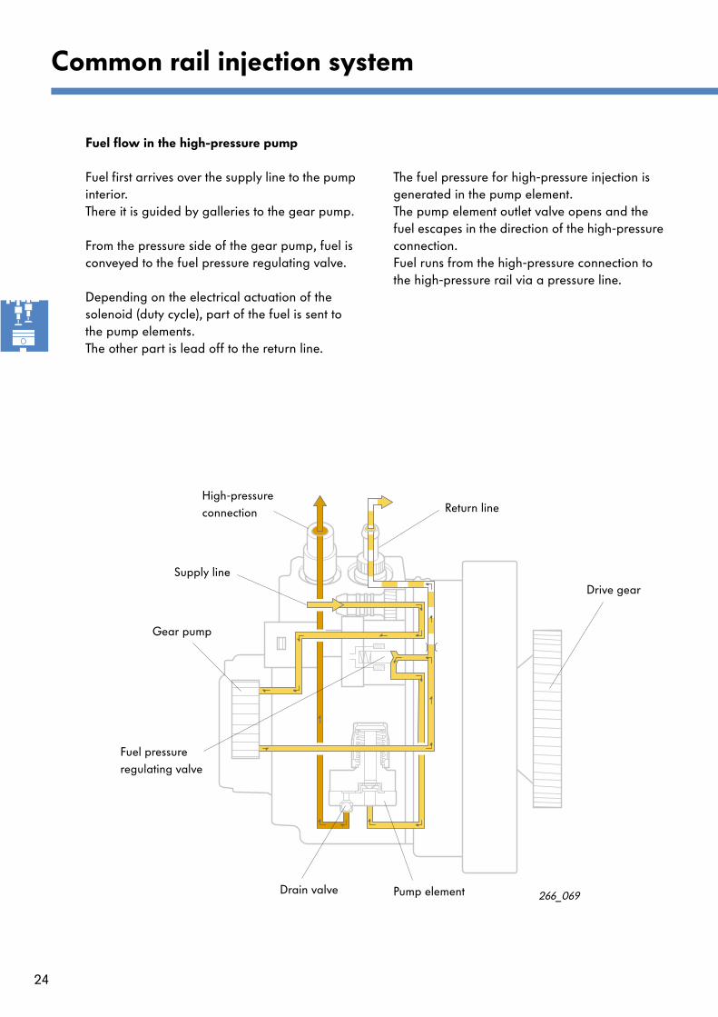
Fuel flow in the high-pressure pump
Fuel first arrives over the supply line to the pump interior. There it is guided by galleries to the gear pump.
From the pressure side of the gear pump, fuel is conveyed to the fuel pressure regulating valve.
Depending on the electrical actuation of the solenoid (duty cycle), part of the fuel is sent to the pump elements. The other part is lead off to the return line.
The fuel pressure for high-pressure injection is generated in the pump element. The pump element outlet valve opens and the fuel escapes in the direction of the high-pressure connection.Fuel runs from the high-pressure connection to the high-pressure rail via a pressure line.
266_069
Return lineHigh-pressure connection
Fuel pressure regulating valve
Gear pump
Pump element
Supply line
Drive gear
Drain valve
25
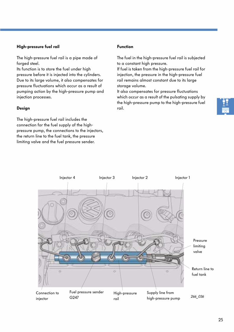
High-pressure fuel rail
The high-pressure fuel rail is a pipe made of forged steel. Its function is to store the fuel under high pressure before it is injected into the cylinders.Due to its large volume, it also compensates for pressure fluctuations which occur as a result of pumping action by the high-pressure pump and injection processes.
Design
The high-pressure fuel rail includes the connection for the fuel supply of the high-pressure pump, the connections to the injectors, the return line to the fuel tank, the pressure limiting valve and the fuel pressure sender.
Function
The fuel in the high-pressure fuel rail is subjected to a constant high pressure.If fuel is taken from the high-pressure fuel rail for injection, the pressure in the high-pressure fuel rail remains almost constant due to its large storage volume.It also compensates for pressure fluctuations which occur as a result of the pulsating supply by the high-pressure pump to the high-pressure fuel rail.
266_036
Pressurelimitingvalve
Return line to fuel tank
Supply line from high-pressure pump
High-pressure rail
Fuel pressure sender G247
Injector 2Injector 3Injector 4 Injector 1
Connection to injector