step phase a ii i
TRANSCRIPT

NASA-CR-| 97856
.._ STEP PHASE A II
VOLUME I TITLE PAGE IExperiment Title: IProposed title - use no acronyms)
I Stellar Interferometer Technology Experiment
Proposing Organizationls):
I Space at Massachusetts Institute of Technology (MIT)
Engineering Research Center the
Jet Propulsion Laboratory (JPL)
Payload S_¢stems Incorporated (PSI)
Principal Investi_lator:
I Professor Edward F. Crawle)_
Experiment Summary:
(Describe experiment, objectives, and
potential benefits in 250 words or less)
I
The MIT Space Engineering Research Center and the Jet Propulsion Laboratory stand ready toadvance science sensor technology for discrete-aperture astronomical instruments such as space-basedoptical interferometers. The objective of the Stellar Interferometer Technology Experiment (SITE) is todemonstrate system-level functionality of a space-based stellar interferometer through the use of enablingand enhancing Controlled-Structures Technologies (CST).
SITE mounts to the Mission Peculiar Experiment Support System inside the Shuttle payload bay.Starlight, entering through two apertures, is steered to a combining plate where it is interfered.
Interference requires 27 nanometer pathlength (phasing) and 0.29 arcsecond wavefront-tilt (pointing)control. The resulting 15 milli-arcsecond angular resolution exceeds that of current earth-orbitingtelescopes while maintaining low cost by exploiting active optics and structural control technologies.
With these technologies, unforeseen and time-varying disturbances can be rejected while relaxingreliance on ground alignment and calibration. SITE will reduce the risk and cost of advanced opticalspace systems by validating critical technologies in their operational environment. Moreover, thesetechnologies are directly applicable to commercially driven applications such as precision machining,optical scanning, and vibration and noise control systems for the aerospace, medical, and automotivesectors.
The SITE team consists of experienced university, government, and industry researchers, scientists,and engineers with extensive expertise in optical interferometry, nano-precision opto-mechanical controland spaceflight experimentation. The experience exists and the technology is mature. SITE will validatethese technologies on a functioning interferometer science sensor in order to confirm definitively theirreadiness to be baselined for future science missions.

IN-STEP PHASE ASUMMARY FORM 1
Experiment Title:
Stellar Interferometer Technology Experiment
(leave blank)
SITE, a HitchHiker-class experiment, is a two-aper-ture stellar interferometer located in the Shuttle
Payload Bay. It consists of three optical benches
kinematically mounted inside a 4-meter precisiontruss structure. Starlight is collected through theapertures and an interference fringe pattern isgenerated. The amplitude and phase of the fringes
provide the information essential for performingimaging and astrometry. To obtain precise fringemeasurements, SITE will employ active optics forwavefront-tilt control and reactionless optical delaylines for active pathlength control. In addition,isolation and vibration suppression will attenuatevibrations caused by payload bay and internaldisturbances which would otherwise blur the
interference fringe pattern.
_ Hitch Hiker
__.:._, Avi o ni cs Ex peri men t
_::d'_ I Support
_u_]
MPESS
The SITE truss is attached to the Mission Peculiar
Experiment Support System (MPESS) located acrossthe payload bay. Signal conditioning, control anddrive electronics are also mounted to the MPESS.
Once on orbit, the Shuttle is aligned to acquire pre-determined stellar targets. Fine alignment isaccomplished by the SITE instrument itself. Theexperiment is controlled from the GSFC POCC.
The mission will quantify the performance and cost-benefits of the various technologies that will enableor enhance space-based interferometry. SITE willdramatically advance technology readiness in timefor NASA's future interferometry missions.
Cost ($K):
Duration:
(Months):
Provide a diagram and description of the experiment above.
i i i I i ,, 1611Phase B Phase C/D Total (all Phases)
I 9 I I 43 I I 52 IPhase B Phase C/D Total (all Phases)

IN-STEP PHASE ASUMMARY FORM 2
(leave blank)
Experiment Title:
Stellar Intefferometer Technology Experiment
Experiment Obiectives (Provide concise statements of main obiectives in bullet formatl:
• To demonstrate and quantify the system-level use of Controlled Structures Technology (CST) to
enable and enhance the performance of an optical interferometer as measured by tracking stellarwhite light fringes.
Justification for space Flight (bullet formatl:
• Flight enables the characterization of static misalignment and nonlinear dynamic effects due to
gravity offload from the isolation and precision mechanisms. This characterization includes
assessing the predictive fidelity of models as well as the ability to align once on orbit.
• Flight allows technology validation in the actual dynamic, vacuum, thermal, radiation and
contamination environment in which future instruments will operate.
• Flight allows measurement of the undistorted starlight that future space-based interferometers
will observe, serving as a metric by which the performance of the technology layers is judged.
Experiment Benefits (Also indicate benefits over competing technologies 1in bullet formatl:
• Reduces the risk and cost of utilizing this technology in advanced optical space systems.
• Maps the cost/performance benefit of applying various technology layers to the achievement of
specific mission goals.
• Allows the rejection of large unmodeled or unexpected on-orbit disturbances through active
control and on-orbit redesign.
• The use of highly active optical and structural subsystems relaxes the reliance on pre-flightalignment and calibration, and the maintenance of their integrity through ground handling andlaunch.
• Applicable to commercially driven applications such as precision machining, optical scanning,and vibration and noise control systems for the aerospace, medical, and automotive sectors.
• Motivates and educates a new generation of students in space engineering and science.
Applications to Future space Missions (bullet format}:
• Space-based optical interferometers for astrophysical astrometry (AIM) and planet detection(ASEPS-1):
- Orbiting Stellar Interferometer (OSI)
- Precision Optical Interferometry in Space (POINTS)
- Small OSI for Narrow-Angle Astrometry with Two Apertures (SONATA)
• Space-based interferometry for high-resolution imaging:
- Laser-Stabilized Imaging Interferometer (LASII)
- Dilute-Lens Imager (DLI)
- Separated-Spacecraft Interferometer (SSI)
- High-Angular Resolution Deployable Interferometer for Space (HARDI)

Stellar Interferometer Tracking Experiment (SITE)
VOLUME II: COST PLAN FOR THE
STELLAR INTERFEROMETER
TECHNOLOGY EXPERIMENT (SITE)
1. SUMMARY
The cost plan shown in Attachments B and C is based on thescientific and technical efforts outlined in Volume I. All
amounts are in constant FY 95 dollars. Broadly stated, the workbreakdown is as follows:
MIT: PI organization responsible for SITE management andsystems engineering.
JPL: Co-Investigator organization responsible for opticalwain and external disturbance isolation.
PSI: Subcontractor responsible for instrument structuraldesign and flight experiment integration.
This cost plan represents an official budget proposal (see attachedForm 1411) with terms being effective from 2/14/95 to 8/14/95.A 6/1/95 start date is assumed.
2. COST PLAN REALISM
Because of the experience of the SITE team in developingand integrating space-qualified hardware and the recent experienceof the MIT-PSI team on other Class-D modified payloaddevelopment efforts such as MODE, MODE-Reflight, andMACE, we feel that the projections made are realistic. Byassigning an experienced space-hardware development team toSITE, we will avoid hidden costs which frequently arise fromlack of familiarity with flight hardware and/or the carrierintegration process which can be quite costly and difficult toestimate. The budget represents a complete program, fromrequirements definition to final report, with no hidden costs.
The method used to arrive at the Cost Plan was as follows:
1. A level 6 WBS was developed and agreed upon by thethree organizations.
2. Each level 3 WBS task was assigned to an organizationbased on expertise and previous experience.
3. Each organization developed a cost plan using aconsistent approach. During this time, a dialog wasmaintained between all three organizations to ensure ahomogenous approach and to maintain the widestpossible experience base.
4. A two day meeting was held at JPL to verify andfinalize the Cost Plan. Cost Plan risks (such asmake/buy decisions on non flight-qualified criticalitems) were also identified and resolved.
5. Finally, a JPL Red Team review was conducted toassess both the technical and cost plans. The budgetcontained herein reflects the review results.
3. FISCAL CONTROL
SITE contractual affairs are administered through the MITOffice of Sponsored Programs using government approvedprocedures. MIT research accounts are audited by the Office of
Naval Research and private accounting firms. The overalladministration and fiscal management of the project is carried outon behalf of the Principal Investigator by the MIT Center forSpace Research. Technical management and schedule control arethe responsibility of the PI/Project Manager. This organizationis the same as that in place for MODE, MODE-Reflight, andMACE.
Volume II: Cost Plan
4. ORGANIZATIONAL IN-KIND FUNDING
As a cost savings, the following funds will be applied to theSITE program using internal sources. By using these internalsources, a total savings of $1,138,000 will be attained.
Personnel WBS S/year Total
• Prof. Crawley 1.1, 1.3, $60,000 $258,00020% of salary during 1.5, 2.1, per year foracademic year applied to 3.1 4.3 yearsSITE project paid throughinternal MIT sources.
• 4 Graduate Students 2.2, 3. l,Stipend & tuition paid 3.2, 3.6,through JPL CSI sources. 4.11 5.2
• Res. Eng. IMOS Modeling 2.2Salary paid through JPLCSI sources.
$175,000 $700,000per year for4 years$120,000 $180,000per year for1.5 years
5. DIRECT LABOR RATES
The labor rates of the actual individual assigned to work on
the program are used by MIT, PSI, and JPL. When newpersonnel are to be hired, a rate commensurate with the expectedsalary level is projected for that individual. The labor rates of theindividuals used in this proposal may be verified by requestinginformation from the local DCAA or MIT Auditor. It should be
noted that Prof. Crawley's salary for the academic year is notbilled to the project; only a fraction of his summer salary isbilled.
6. INDIRECT RATES
The MIT employee benefit and indirect expense rates are:
MIT FY Period EB Rate IE Rate
1995 7/1/94- 6/30/95 43.1% 52.0%
1996 7/1/95- 6/30/96 43.5% 52.0%
1997 7/1/96- 6/30/97 43.5% 56.0%
1998 7/1/97- 6/30/98 43.5% 60.0%
1999 7/1/98- 6/30/99 43.5% 60.0%
The stated Employee Benefit rate is applied to all Salaries
and Wages with the exception of undergraduate students whichcarries a 6.5% rate. The Indirect Expense rate is applied to theModified Total Direct Cost (MTDC) base in accordance withOMB Circular A21. In accordance with a recent agreementbetween MIT and the local ONR Representative, the CSRTechnical and Administrative Support and the Allocated
Expenses are also removed from the MTDC Base. The rates forMIT FY 1995 are those negotiated with the Government and
those for the subsequent years are estimates generally accepted forproposals within MIT. Each year the rates billed will be theapproved negotiated rates for that year and may differ from theabove.
7. PROGRAM CONTINGENCY
The SITE team feels that is important to specify budget
contingency as an indication of the potential overrun that couldoccur in the development and procurement of certain high riskitems. Notice that a detailed design and evaluation exercise wasconducted in Phase A in order to reduce the risk of such overruns.This, in combination with the extensive experience of the SITE
team, was successful in reducing development risk as indicated inthe Major Equipment Table. In light of this, the JPL Red Team
Massachusetts Institute of Technology Page 1 Space Engineering P_,search Center

Stellar Interferometer Trackinp[ Experiment (SITE)
felt that a 10% contingency was appropriate. While thiscontingency is not included in the budgets summarized in
Attachments B and C, a 10% increase in the budget (i.e.,$1,216,100), concentrated primarily in fiscal years '96, '97, and'98, will cover all unforeseen hardware design and procurementdifficulties. The maturity of the Conceptual Design Document
and Implementation Plan warrants this level of contingency.
8. SUBCONTRACTS AND REVIEWS
This proposal contains the estimated cost of a proposedsubcontract by MIT to Payload Systems Inc. In view of thetime consl:raints imposed by the sponsor deadlines, MIT hasconducted only a limited analysis of the subcontractor's costproposal as part of our administrative review. A more extensive
analysis will be performed by CSR and the MIT PurchasingOffice after the award is made to MIT and the subcontract is
negotiated.
At this time the following can be stated: Fringe Benefitrates and Indirect Cost rates have been verified with the
subcontracting institution as those currently in use for itssubcontracting work; Labor rates have been reviewed and appearreasonable given the proposed work; Equipment, Travel,Materials & Supplies, and other Miscellaneous Direct Costs have
been reviewed and appear reasonable given the proposed work.
9. COST TABLES
The following tables contain all costing informationrequested in the Guidelines for In-Step Phase A Deliverables.All cost items are tied direedy to the WBS and summarized bytask and phase in the Attachments. All cost estimates are based
Volume II: Cost Plan
on the best information of the SITE team at the time of sub-
mission, and reflect the experience of the team in designing,fabricating, certifying, and performing successful flightexperiments on the Orbiter. As SITE will be a Class-D payload,commercial off-the-shelf (COTS) parts will be used wherepossible. We do not presendy anticipate the procurement of anyparts with longer lead times than 24 weeks. A detailedassessment of critical, long lead time items will be conductedearly in Phase B. Cost estimates for parts and travel reflectcurrent prices and fares.
Attachments B and C are included at the end of this Cost
Volume. In addition, three tables providing additional cost detailhave been provided: direct labor, materials, and travel. Costs inthese supporting tables are unburdened values, so that directcomparisons with Attachments B and C can be made.Information is presented broken out by SITE partner (MIT, PSI,
or JPL) and by appropriate category. Subtotals are provided forM/T and PSI since PSI is formally a subcontractor to MIT.
9.1 Direct Labor
Table II-1 describes the break out, by job category forthe entire SITE program. When over 100% of a job category islisted, then more than one individual are in that category. Thetable only accounts for In-Step contributions. Job categorieswith an asterisk (*) indicate that non-M-Step funding will be usedto augment the listed labor effort as described in Section 4. Tech& Admin Support is the standard rate charged by the Center forSpace Research for fiscal administration. Percentages assume aconstant level of staff'mg and do not reflect variations inherent in
any flight development program.
(* indicate that non-In-Step fundln_ will be used
Employee %
Table II-1 Direct Labor
to supplement the labor efforts listed in this table =us described In Section 4).Phase B Phase C/D Totala
Hrs. Cost % Hrs. Cost Hrs. Cost
/tAfT Proj. ManJPl (Summer)* 20%
Co-Principal Investigator 80%Senior Scientist
Engineering Staff 24%
Support Staff 16%Graduate Research Asst." 200%
Tech &Admin SupportMI T Totals:
PSI Project Manager/Scientist 48%Administrative Assistant 2*/0
Quality Assurance Eng. 6%
Electrical Engineer I 56%
Electrical Engineer 2 30%
Integration Manager 480
Mechanical Engineer 1 90*/0
Mechanical Engineer 2 39%
Software Engineer 1 52*/0
Software Engineer 2 22*/0Technician 7%
PSI Totals:
MIT and PSI Totals:
JPL Manager 23%
Optical Engineer 100"/.
Mechanical Engineer" 340%
Electrical Engineer 66%
Software Engineer 43%Technician 42°/=
Quality Assurance
SecretaryAdministrative Assistant
JPL Totals:
TotalProgram:
48 3,435 20*/0 176 13,829 224 17,264
1,152 24.148 80% 5,248 118,939 6,400 143,085
35% 2,327 52,748 2,327 52,748
352 10,309 6% 400 12.280 752 22,589
224 3,939 _35% 2,288 44.488 2,512 48.427
2,880 23,494 200% 13,120 115.634 16,000 139,128
6,923 26,783 33r7064,656 72.246 23,559 384,701 28.215 456,947
691 24,561 40% 2,037 72,402 2,728 96,963
34 516 39'0 154 2,339 188 2,855
91 3,180 7% 380 13,281 471 16,481
810 22,320 53*/0 2,962 81,608 3,772 103,928
428 7,211 100% 5,758 97,008 6,186 104,219
691 10,917 84% 4,689 74,082 5,380 84,999
1,290 42,135 100% 5,112 166,971 6,402 209,106
564 12,666 86*/0 4,834 108,556 5,398 121,221
750 21,471 830 4,633 132,635 5,383 154,106
317 6,860 67% 3,742 80,982 4,059 87,842
104 1,752 100"/o 5,758 97,008 5,862 98,760
5. 770 153,589 40,059 926.872 45,829 1,080,461
10,426 225.835 63,618 1,311.573 74,044 1.537,408
329 12,338 40% 2759 103,482 3,088 $115.8001442 44,702 80% 5228 162,068 6,670 $206,770
4893 102,974 300*/. 20607 434,866 25,500 $537,840
945 29,295 100% 7171 222,289 8,116 $251,584
616 19,096 100% 7313 226,697 7,929 $245,793
600 13,200 200% 12900 283,800 13,500 $297,000
30*/0 1920 57,600 1.920 $57,500
330 2172 39,096 2,172 $39,09617% 1086 23,892 1,086 $23.892
8,825 221.605 61,156 1,553,770 69.981 1,775,375
19,251 447.440 124,774 2,865,343 144.025 3,312,78.q
Massachusetts Institute of Technology Page 2 Space Engineering P_search Center

Stellar Interferometer Tracking Extmriment ¢SITE)
9.2 Major Equipment List
Table II-2 contains the major equipment costs along
with a breakout describing the procurement lead time, risk
category, and cost basis. All significant major items are
included. Miscellaneous items (fasteners, cabling, connectors,
etc.), are accounted for within each major component. A phase
by phase breakout is not provided since some procurement
extends across several phases.
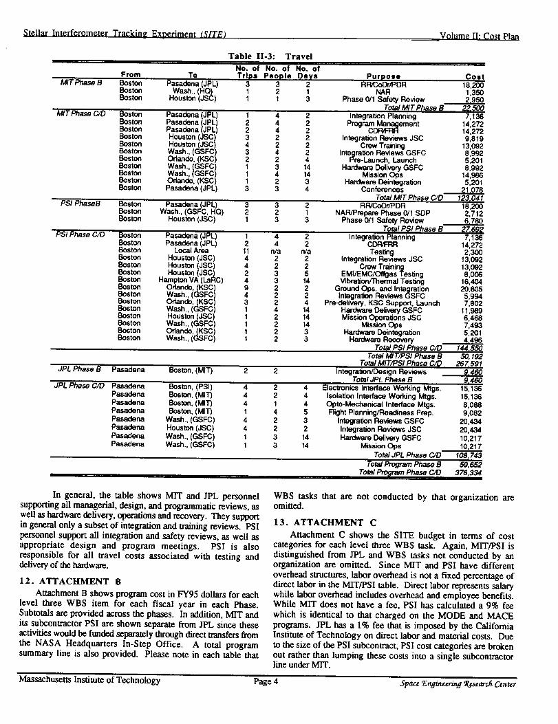
9.3 Travel
Table 1I-3 describes the expected travel costs for SITE
including the relevant event, the number of trips, duration, and
Equipment
Volume 11: Cost Plan
number of people. Because it is not known which NASA
center would be assigned oversight of SITE, a conservative
travel estimate is presented. Obviously, if JPL is assigned
contractual oversight responsibility, some of the travel costs
may be deferred. Additionally, Goddard Space Flight Center
will decide how much support is required by the SITE team for
integration and safety reviews as part of the normal integration
process. For the purposes of this budget, it was assumed that
some support would be required at all major reviews, either atJSC or KSC. The SITE team will also endeavor to utilize
video and teleconferencing as much as possible to reduce the
travel cost of this program.
Table 11-2: Major Equipment List
WBS LIT Risk Basis Phase Cost
M/T Truss Prototype 3.1.2 short N/ALab Support Equipment 3.1.2 short N/A
PSI Blueprints, Drawings, Etc. 3.7.1 short N/ASoftware Analysis Tools 4.3.3 short 1Testing, Analysis, Vendor Eval. 2.4.3 short 1MPESS Interface 3.1.1 short 2
Precision Optical Bench 3.1.2 tong 2Thermal Control Equipment 3.1.4 long 2Containment & Shutters 3.1.5 short 2Experiment Control Computer 3.5.1 short 1 to 2Instrument Control Computer 3.5.2 short I to 2Signal Conditioning System 3.5.3 long 1 to 2Signal Amplifier System 3.5.4 long 1 to 2ESM Containment 3.5.5 long 2Power Distribution System 3.5.6 short 2Data Handling & Storage Sys 3.5.7 long 1 to 2Test Equipment and Fixtures 3.7.1 short 1 to 2Trenspertation Containers & Hndlng 3.7.1 short 1 to 2Power & Avionics Simulation 3.7.1 short 1Optical Test Equipment 3.7.1 short 1Portable Clean Room & Supplies 3.7.1 short 1Design & Fabrication Equip. & Supp. 3.7.1 short 1Ground Station 3.7.2 short 1Structure/Isolation Test Facilities 4.1.2 short 1
Accept/Cert Testing and Equip. 4.2.6 short 1Software Analysis Tools 4.3.3 short 1
Total MIT and PSi:
JPL Metrology Laser Prototype 3.4.3 long N/AMetrology Laser (flight) 3.4.3 long 4Isolators 3.2.1 2Isolator Latches 3.2.2 3Isolation Support Equipment 3.2.1Siderostats (proto) 3.3.1 long N/ASiderostats (flight) 3.3.1 long 3Alignment Mirrors 3.3.3 long 2Accelerometers 3.3.4 long 1CAD camera 3.4.4 long 2Test Facilities Opto Mechanical 3.3.1 n/a 1Test Facilities Optics and Detectors 3.4.1 n/a 1Test Facilities Subsystem Integration 4.1.1 n/a 1Beam Compressors 3.4.1 long 1W'rD Camera 3.4.4 long 3Modulators 3.4.2 short 2Fast-Steering Mirror 3.3.1 short 2Calibration Source 3.4.5 short 1Optical Delay Line 3.3.2 3
Total JPL
Total Program:
heritage (MIT Interf. Testbed) BIC/D 175,590estimate + quote C,_ 38,950estimate + quote B 3,800
quote B 4,500quote CaD 6,500
estimate CaD 13,605heritage (MACE/MODE) C4_ 149,250
estimate + quote (materials) C_,¢D 46,g48estimate C/D 34,650
heritage(MOOE/MACE) C,O 14,275heritage (Palomar Testhed) CaD 71,100heritage (Palomar Testhed) C_,,O 37,200
heritage (MODE/MACE) CaD 96,175heritage (MOOE/MACE) CaD 29,4 70heritage (MODE/MACE) C,O 46,400heritage (MODE/MACE) C_ 18,650heritage (MODE/MACE) C_,,.O 63,050
estimate + quote C/D 15,109estimate C_,/D 8,140
quote C/D 28,700quote C.K) 27,365quote CK) 46,620
estimete + quote CJD 46,400quote C/D 37,500quote C/D 127,500quote C/D 36,000
estimate Bestimate CaD
1,223,44832,45364,90772,69598,33438,944
estimate + quote B 32,453estimate + quote C_ 162,267
quote (COTS) C,.O 21,636quote (COTS) C/D 27,044
heritage (Mars Pathfinder) C.,K) 162,267estimate + quote _ 178,493estimate + quote C/D 221,764estimete + quote C/D 140,631
hedtage (multiple missions) C/D 21,636quote (Lincoln Laboratory) C/D 324,533
estimate C40 32,453quote C,O 25,963
estimate C.,/D 10,818heritage (MPI testbed) + estimate 149,610
Lead Time (I/T):long - manufacture of this item exceeds 6 weeks, short - manufacture of this item either done in-house or less than 6 weeks.
Risk:
1 - off-the-shelf hardware meets both functional and environmental requirements.2 - standard engineering is required for component to meet functional and environmental requirements.3 - significant design and qualification are required for component to meet environmental and functional requirements.4 - off-the-shelf hardware is available to meet functional requirements but environmental qualification is unknown.
Basis: explanation of selections in lead time and risk columns: quote, estimate or heritage.
Massachusetts Institute of Technology Page 3 Spa= _n_mtwi_ ff_gaeardi Certur
Stellar Interferometer Tracking Experiment (SITE) Volume II: Cost Plan
From ToMIT Phase B Boston Pasadena (JPL)
Boston Wash., (HQ)Boston Houston (JSC)
Table 11-3: Travel
No. of No. of No. ofTrips People Dsys
3 3 21 2 11 1 3
Purpose Cosl
MIT Phase C/D
PSI PhaseB
Boston Pasadena (JPL)Boston Pasadena (JPL)Boston Pasadena (JPL)Boston Houston (JSC)Boston Houston (JSC)Boston Wash., (GSFC)Boston Orlando, (KSC)Boston Wash., (GSFC)Boston Wash., (GSFC)Boston Orlando, (KSC)Boston Pasadena (JPL)
1 4 22 4 22 4 23 2 24 2 23 4 22 2 41 3 141 4 141 2 33 3 4
RPJCoDr/PDR 18,200NAR 1,350
Phase 0/1 Safety Review 2,950Total MIT Phase B _,_
Integration Planning 7,136
Program_ement 14,27214,272Integration Reviews JSC 9,819
Crew Training 13,092Integration Reviews GSFC 8,992
Pre-Launch, Launch 5,201Hardware Delivery GSFC 8,992
Mission Ops 14,986Hardware Deintegration 5,201
Conferences 21.078 tTotal MIT Phase C/D 123,041
RWCoOr/PDR 18,2001 NAR/Prepare Phase 0/1 SDP3 Phase 0/1 Safety Review
Total PSI Phase B2 Integration Planning2 CDRtFRR
rVa Testing2 Integration Reviews JSC
Boston Pasadena (JPL)Boston Wash., (GSFC, HQ)Boston Houston (JSC)
3 3 2
PSI Phase CtD Boston Pasadena (JPL)Boston PasadenaBoston Local _(JaPL)
Boston Houston (JSC)Boston Houston (JSC)Boston Houston (JSC)Boston Hampton VA (LaRC)Boston Orlando, (KSC)Boston Wash., (GSFC)Boston Orlando, (KSC)Boston Wash., (GSFC)Boston Houston (JSC)Boston Wash., (GSFC)Boston Orlando, (KSC)Boston Wash., (GSFC)
2 21 3
1 42 411 n/a4 24 22 34 39 24 23 21 41 21 21 21 2
2 Crew Training5 EMIAEMC/Offgas Testing
14 Vibration/'rhermal Testing2 Ground Ops. and Integration2 Integration Reviews GSFC4 Pre-detivery, KSC Support, Launch
14 Hardware Delivery GSFC14 Mission Operations JSC14 Mission Ops3 Hardware Deintegration3 Hardware Recovery
Total PSI Phase C/D
2,7126,780
27,6927,136
14,2722,300
13,09213,0928,006
16,40420,8055,9947,802
11,9896,4687,4935,2014,496
144,550Total MIT/PSI Phase B 50,192
Total MIT/PSI Ph__seC/D 267,591Integration/Design Reviews
Total JPL Phase BJPL Phase B Pasadena Boston, (MIT) 2 9.,w_
9,460JPL Phase C/D Pasadena Boston, (PSI) 4
Pasadena Boston, (MIT) 4Pasadena Boston, (MIT) 4Pasadena Boston, (MIT) 1Pasadena Wash., (GSFC) 4Pasadena Houston (JSC) 4Pasadena Wash., (GSFC) 1Pasadena Wash., (GSFC) 1
4 Electronics Interface Working Mtgs. 15,1364 IsolaSon Interface Working Mtgs. 15,1364 Opte-Mechanical Interface Mtgs. 8,0885 Right Planning/Readiness Prep. 9,0823 Integration Reviews GSFC 20,4342 Integration Reviews JSC 20,434
14 Hardware Detivery GSFC 10,21714 Mission Ops 10,217
Total JPL Phase 00 108, 7,¢_Total Program Phase B 59,652
Total Program Phase C/D 376,33,f
In general, the table shows MIT and JPL personnel
supporting all managerial, design, and programmatic reviews, as
well as hardware delivery, operations and recovery. They support
in general only a subset of integration and training reviews. PSI
personnel support all integration and safety reviews, as well as
appropriate design and program meetings. PSI is also
responsible for all travel costs associated with testing anddelivery of the hardware.
12. ATTACHMENT B
Attachment B shows program cost in FY95 dollars for each
level three WBS item for each fiscal year in each Phase.
Subtotals are provided across the phases. In addition, MIT and
its subcontractor PSI are shown separate from JPL since these
activities would be funded separately through direct transfers fi'om
the NASA Headquarters In-Step Office. A total program
summary line is also provided. Please note in each table that
WBS tasks that are not conducted by that organization areomitted.
13. ATTACHMENT C
Attachment C shows the SITE budget in terms of cost
categories for each level three WBS task. Again, MIT/PSI is
distinguished from JPL and WBS tasks not conducted by an
organization are omitted. Since MIT and PSI have different
overhead structures, labor overhead is not a fixed percentage of
direct labor in the M1T/PSI table. Direct labor represents salary
while labor overhead includes overhead and employee benefits.
While M1T does not have a fee, PSI has calculated a 9% fee
which is identical to that charged on the MODE and MACE
programs. JPL has a 1% fee that is imposed by the CaliforniaInstitute of Technology on direct labor and material costs. Due
to the size of the PSI subcontract, PSI cost categories are broken
out rather than lumping these costs into a single subcontractorline under MIT.
Massachusetts Institute of Technology Page 4 Space Engineering P,_search Center

Stellar lnterferometer Technolo._y Experiment (S;rE]
PART A RELEVANCE AND TECHNICAL
MERIT
A.I FUTURE NASA APPLICATIONS
The Stellar Interferometer Technology Experiment
(SITE) provides direct technology validation and infusion into a
variety of envisioned space-based optical interferometers. It is
clear that interferometers operating in the ultraviolet, visible, and
infrared wavebands represent the next great leap forward in
space-based astronomy and astrophysics. As stated in the
Bahcall Report, interferometry is the only known method to
significantly improve (by orders of magnitude) the angular
resolution of current astronomical telescopes and thereby meet
several key scientific goals of the 21st century: extra-solar
planet detection, the precise measurement of galactic and cosmicdistance scales, measurement of stellar diameters, and resolution
of close binaries. NASA Astrophysics (Code SZ) and Planetary
(Code SL) Divisions share an interest in these science goals.
Code SZ is considering an Astromctric Interferometer
Mission (AIM) as its next new lnission start after SIRTF. The
Orbiting Stellar Interferometer (OSI) at JPL and the Precision
Optical Interferometer in Space (POINTS) at SAO are the
leading candidates for AIM, whose science goal is to map the
celestial sphere to 5 micro-arcsecond accuracy. Code SZ is
considering imaging interferometers such as the Laser Stabilized
Imaging Interferometer (LASII), High Angular Resolution
Deployable Interterometer for Space (HARDI), the Separated
Spacecraft lnterferometer (SSI), and the Dilute Lens Imager
(DLI) as potential follow-on missions to the Hubble Space
Telescope (HST). Code SL is actively pursuing optical
interferometry for extra-solar planet detection under its
Astronomical Search for Extrasolar Planetary Systems (ASEPS)
Program. POINTS and the Small OSI for Narrow Angle
Astrometry with Two Apertures (SONATA) are leading
candidates for ASEPS- 1, the first space mission in the series.
Space interferometry will require a significant infusion
of advanced technologies beyond those required for ground
operation, due primarily to platform stability issues.
Recognizing the critical enabling role that advanced technology
will play in the success of space optical interferometry, Code SZ
has produced, as part of its AstroTech 21 Program, a
"Technology Requirements Plan for Space Interferometry
Missions." SITE is explicitly mentioned several times in this
Interferometry Technology Plan (ITP) as a system-levelvalidation of mission-critical technology that is integrated with
the schedule of other key technology development efforts.
A.2 TECHNICAL RELEVANCE TO NASA
An interferometer is fundamentally a sparse aperture
optical system where small, spatially distributed collecting
apertures are combined to synthesize the performance of a
single, larger aperture. An optical interferometer can be used for
high resolution imaging as well as extremely precise astrometry
(the mapping of stellar positions in the sky). SITE will be the
first space-based optical interferometer and will investigate thevalue of advanced technologies for enabling successful
interferometric measurements on orbit. Specifically. SITE will
flight validate the five highest priority intcrferometcr component
technologies (as listed in the Code SZ ITP):
[, metrology and starlight detection systems
lI. fine pointing and vibration isolationIII. active delay lines and siderostats
[V. quiet structures and st_bsvstemsV. high fidehty integrated niodeling
Furthermore, it is the systems synthesis of these technologies on
orbit that poses a greater challenge than any of the individual
technologies: SITE will demonstrate this system functionality in
VOI.UME I : TECHNICAL
the operational environment of NASA's future missions.
Interferometer technology has been aggressively
pursued over the past six years by the NASA Office of Space
Access and Technology (Code X) with the JPL Micro-Precision
Control-Structure Interaction (CSI) Program and with MIT's
USERC in Controlled Structures Technology (CSTI. Of the five
categories listed above, items II-V are Controlled Structures
Technologies. These are recognized as a critical subset since,
without them, space-based intcrferometry will not be possible.
A principal difficulty with perfo,ming optical
interferometry in space arises from structural flexibility and
spacecraft disturbance sources: tim optical platform can simply
not be as massive and stable as ground based instruments, vet
mechanical stability of 10 to 20 nm is still required. In order to
retain traceability, of SITE to the future missions that it is
intended to benefit, a scaling analysis was performed to
normalize the mass of SITE to these proposed missions.
Table A-I.: Scale of SITE with respect to future instruments.
Instrument .",lass (M) # EIo (E) Baseline IB) MtEtB
POINTS 374 kg 4+1 +3 2 in 23
OSI 1250 kg 6+1+3 7 in I_
SONATA 790 kg 2+ 1+3 7 in 19
DLI 2969 kg I I+1+3 25 m 8
SITE 200 k._ 2+ 1 4 m 17
Table A-I lists the parameters of this scaling analysis:the mass, number of concentrated elements, and baseline for four
envisioned missions as well as SITE. Concentrated elements are
relatively massive subsystems such as subapertures, combining
plates, and spacecraft bus components (e.g., reaction wheels).
Spacecraft buses are approximately three times the mass of these
other elements. OSI has ten concentrated elements arising from
its six subapertures, one combining plate, and a spacecraft bus
(6+1+3). SITE has two subapertures, one combining plate andno bus elements (2+1). Notice that the mass. number of
elements, and baselines of these missions vary by a factor of ten.
However, the ratio of mass per concentrated element perbaseline results in a relatively limited ran,,e of values. This ratio
was determined to be a relevant discriminator because it
represents an intrinsic feature of an interferometer. Since the
design goal is to separate one subaperture from the others by a
specified baseline, the mass with which this separation isachieved provides a basis for comparison between otherwise
radically different interferometer concepts. This ratio for SITE
has been intentionally made comparable to these envisionedmissions.
SITE's technology customers are clearly NASA Codes
SZ and SL. To ensure maximum leverage of this program's
results. SITE has adopted two transfer pathways. First, the team
contains a leading world expert in ground and space-based
optical interferometer design, fabrication, and operation.Second, a Science Advisory Committee will be formed in Phase
B consisting of the world's other leading experts, from whom
membership interest has been already expressed. These two
pathways ensure maximum relevance to future NASA programs.
A.3 BENEFITS OF THIS TECHNOLOGY TO NASA
SITE provides direct benefit to NASA's interferometer
missions because it buys down mission risk• The benefit issystems oriented because it demonstrates that the various
technologies, that have been developed and operated on the
ground, work in harnlony in the extreme environment of earthorbit. The single best way to demonstrate system level
technology readiness is to build an actual space-based
intcrferometer, capable of acquiring and tracking stellarinterference fringes. This proves unambiguously the feasibility
MASSACHUSETTS INSTITUTE OF TECHNOLOGY PAGE 5 ,3:I'.q¢ "£ '_:k (; I:'CE'r'_ I_ __; '__Lq't2 7"_¢ 2*( ( :E3,"FG_.
ar%-ref'-i ......

StellarIntefferometerTechnology,Experiment(sirE)
Table A-2.: Relative
Technology Area
Laser Metrology
Integrated Modeling
Vibration Isolation & Pointing
Active Delay Lines
Quiet Structures
benefits of technologies
Astrometry Orbital Imaginglnterferometer(AIM)
: : high I
to different mission architectures.
Lunar
Interferometer
high _: "
VOLUME 1: TECHNICAL
. high :
medium
Multiple
Spacecraft
Precision Deployment
Thermally Stable Optics
Advanced Materials
Electric Propulsion
Contamination Prevention Systems
Ground Integration Testbeds
Flight Experiments
high
medium
medium
low
low
high
high '
high
medium
medium
low
low
high
high
medium
high
medium
low
high
high
high
high
high
high
high
medium
of space interferometry, demonstrates system integration of the
critical component technologies, and quantifies each
technology's contribution to the overall optical performance
metric (viz., stellar fringe "visibility"). This latter feature of
SITE (i.e., component technology characterization) is where the
real engineering science lies. This knowledge will allow future
mission designers to confidently perform quantitative trade,
performance, and cost/benefit studies to select those component
technologies which are appropriate for their particular missionneeds. This is the essence of risk reduction.
In addition, the success of SITE will have a profound
impact on reducing the cost of future interferometers by flight
qualifying systems and procedures which have been identified as
fundamental cost drivers in previous interferometer studies: thelack of space-qualified versions of the necessary subsystems and
the lack of experience in the integration of these subsystems intoa working space instrument. Finally, SITE will benefit a broad
class of potential NASA optical interferometers, not only one or
two currently planned systems. This is illustrated in Table A-2
(taken directly from the ITP), where the benefit of the relevant
medium
medium
medium
high
low
high
high
technologies for the different interferometer architectures is
rated. The technologies that SITE will address are shaded.
For example, SITE, in developing and testing
technologies for a structurally connected interferometer, will
nevertheless have a major impact on future interferometer
missions using multiple spacecraft or virtual structures. Many
component technologies such as high speed laser metrology and
active optical components will be flight qualified. More
important, the essence of interferometry is the coordinated andautomated interaction of many active systems with extreme
accuracy. Demonstration of this technology will be a significant
US leadership in space arises from the use of SITE as an
educational focus for the next generation of aerospace leaders.Over 20 students will work on SITE over the course of the
project. If SERC's experience in MODE and MACE is any
guide, SITE will prove an unparalleled motivator, attracting the
best and brightest young minds.
A.5 TIMELINESS OF FLIGHT RESULTS
As explicitly mentioned in the ITP, 1999 is the need
date for the system-level technology validation in space that
SITE provides. Therefore, SITE will allow a timely assessment
of technology readiness for the start of AIM and ASEPS- 1. This
puts SITE on an aggressive but attainable schedule. Of course,
the AIM and ASEPS Programs are subject to year-to-year
reviews by NASA. Such reviews are ongoing (e.g., in Code SZ
this review is part of the evaluation of submissions to the New
Mission Concepts NRA) and could well change the timetablesshown in Figure A-1. Nonetheless, optical interferometry will
play a central role in NASA's future. SITE will help pave the
way for that future.
93 i 94 i 95i 96 i 97 i 98 i 99 _00 ! 01 i 02i 03 i 04 i 05 i 06 i 07 i 08
C/D "_7 Launch
A B C/D
I I V Launch
A B C./D
/_. I I I1_ Launch
SITE ,_
AIM
ASEPS-1
milestone for connected as well as unconnected interferometers.
A.4 CONTRIBUTION TO US LEADERSHIP IN SPACE
By virtue of the Hubble Space Telescope (HST), the USis already the acknowledged world leader in space-based
astronomy and optical systems. In order to maintain and extendthis leadership position, the US must be the first nation to fly an
optical interferometer. SITE is a critical stepping stone toward
this goal. SITE represents a unique collaboration between
NASA Codes X and S where the technology development is
driven directly by the needs of the customer on a schedule that is
aligned to have maximum impact on the customer's major
programs. As such, SITE exemplifies a new process for
technology infusion that, if broadly adopted, will give the US a
competitive advantage by virtue of the speed with which it can
apply new space technology for near term mission payoff.
Of course, another very tangible contribution of SITE to
Figure A-I: Mission timetables relative to SITE
A.6 DUAL-USE, AND COMMERCIALIZATION PLAN
While the connectivity of SITE to future NASA
missions is inherent and obvious, its applicability to broader
dual-use commercial applications may not be as apparent.
However there is significant commercial potential in SITE
technology, and the SITE team has a plan to transfer this
technology to the appropriate commercial sectors. To better
understand this potential, one must consider SITE as a system,
made up of subsystems and components. At each level there are
possibilities for commercialization.
At the system level, SITE is a precision space-based
optical system. The market for these systems is modest in size,and consists of future NASA science missions, defense
observational systems, and commercial earth observing systems.
In order to transfer the system-level technology, the SITE team
includes Lockheed Missiles and Space Company, the Boeing
Company, and Orbital Science Corporation. All of these
MASSACHUSETTS INSTrIVTE OFTECHNOLOGY PAGE 6 _AC'Z E_IN_:_ ___CH C'_N_--_

Stellar lnterferometer Technology Experiment (sirE)
companies are potential prime contractors for future government
and commercial observational systems.
At the subsystem and component level, the issues which
SITE technology addresses are significantly broader. The
essence of SITE is a Layered vibration reduction and isolation
architecture which operates from low frequency through theacoustic range. Therefore, SITE technology can be applied to a
broad class of problems. As shown in Table A-3, at tile
subsystem level, SITE includes precision metrology, precision
optical control, and structural control subsystems. These
subsystem technologies can be incorporated into precision
machining systems, optical tooling, motion compensation for
cameras and video, robotic systems and precision assembly
facilities. For example, a precision micro-component
manufacturing facility could use a SITE-like optical metrology
subsystem to locate an effector, and a SITE-like vibration
absorbing system to maintain position. Four companies are
included in the SITE team at this subsystem level. Hughes
Danbury Optical Systems is interested in adaptive optical
systems for a variety of applications, as is Litton Itek Optical
Systems. Honeywell is a controls company with both space and
commercial business areas. They are interested in both structural
control and isolation in a number of industrial applications.
Boeing, in addition to being a spacecraft builder, is amanufacturer of a lar,,e number of high value commercial
products, and is interested in determining if SITE technology is
applicable to their manufacturing processes.
At the component level, the applicability of SITE
technology is even broader. In many systems and products, from
refrigerators to sports equipment to automobiles, there is
unwanted sound and vibration. The SITE approach to
penetrating this large market is to include, on the team three
growing component manufacturers who aspire to build and sell
to a wide market: ACX, CSA, and Midd Technologies. ACX isa small business and manufacturer of vibration and motion
control systems fl)r large volume commercial applications. CSAis a small business consultant and manufacturer of vibration
isolation and damping systems. Midd Technologies is a small
business and consultant specializing in nonlinear modeling and
innovative mechanism design ['or the aerospace and automotive
industries. We feel that through these three companies, SITE
technology has the potential for penetrating a large number ofeventual commercial markets.
Table A-3.: Matching of applications and industrial customers with
SITE technology tiers.
Technology Potential Applications CompaniesSystem: Earth sensing, laser Lockheed, OSC,Space based communicatmns, disaster Boein_optical systems relief sensin_Subsystem: Precision machining, optical HDOS, Litton.Metrology, coolin_ robotic alignment Honeywell.precision optical, and guidance (welding, Boeinestructural control inspection, etc.)Components: Levelinz for manufacturinz. ACX, CSA, MiddIsolatmn, active base isolation in buildings[ Tech.structural turbine blades, environmentaldamping & industrial noise control
It is important to understand that these levels are not
distinct: technology must flow from the component developers
to the subsystem and system-level companies as it matures and
becomes more affordable and reliable. Conversely, COlnponentdevelopers must understand the needs of the other two levesl in
order to focus their product-development efforts. As a result, the
SITE program views the progression of advanced technologyfrom components to system integration to be as important as
targeting each of these levels individually. Therefore, a
concentrated effort was made to attract companies from eachlevel which have similar commercial interests in order to
VOLUME I : TECHNICAl.
develop a healthy teaming environment.
Having identified commercial applications of SITE
technology at the system, subsystem, and component levels, a
technology commercialization plan was set in place. Letters
were sent to numerous companies in each level to solicit specific
interest in the SlTE -developed technologies. The SITE team hasreceived letters from the companies listed in Table A-3 which
express substantial interest in participating in the SITE
Commercialization Plan. This plan has three aspects:
Commercial Industrial Review Committee (CIRC).
This Committee is composed of representatives of all the
participating companies, and is analogous to a Science Advisor?'
Committee. It will meet regularly throughout the program, and
will provide feedback on commercial applications. Its functions
are to keep industrial members current on the technology
evolution, identify specific areas of commercialization, and
provide a network of members who might propose in response to
future solicitations for technology transfer andcommercialization, such as the NIST, TRP. STTR, and SBIR
programs.
Technology Commercialization Plan. When the
CIRC identifies possible commercial pathways, an integrated
product development team may be formed between the SITE
team and industry. This team will examine the feasibility of
specific commercial applications. The SITE team members will
produce a technology assessment report and industrial memberswill produce a technology commercialization plan. SITE team
members are prepared to become involved in actual product
development spin-offs. Up to $20.000 of the SITE budget has
been allocated to this activity.
Industry Subcontracts. The SITE team is baselined to
build all components. However, early in Phase B a series of
make or buy decisions will be made, Where appropriate,
industrial team members will be solicited in these procurements
for specific components. This will provide a hardware pathway
to integrate industry members into the SITE team.
PART B TECHNICAL
B.1 EXPERIMENT BACKGROUND
B.I.1 Significance and Relationship to State-of-the-Art
The significance of SITE is that it will be the first in-
space, system-level demonstration of technology that is critical
to the success of stellar optical interferometry. This technology
demonstration will pave the way for future missions identified in
Section A.I. Optical interfcrometry, by combining the light
from widely-separated collectors, has the ability to provide the
angular resolution of a filled-aperture telescope whose diameter
is equal to the separation of the collectors. Angular resolution,
the ability to resolve fine detail, grows with the diameter of the
aperture (for a telescope) or with the separation of the collectors
(for an interferometer). The 10-m Keck Telescope on MaunaKea is the world's largest filled-aperture optical telescope.
However, ground-based optical interferometers, with baselines
of many tens of meters, have been built and operated providing
angular resolution exceeding that of Keck at a small fraction of
the cost. Building an equivalent filled-aperture telescope
providing the resolution of these interferometers would be
prohibitively expensive using any foreseeable technology.
Movin_ to space provides the same advanta_,es for
interferometers as for conventional telescopes: the removal of
the turbulent and partially opaque atmosphere. Sensitivity is
greatly increased, as short exposures are no longer necessary tofreeze the turbulent atmosphere. Diffraction-lilnitcd
observations are possible over very wide fields of view, much
greater than would be possible with any compensated imaging
scheme on the ground. High dynamic range observations of
MASSACHUSETTS INSTITUTE OF TECHNOLOGY PAGE 7 S'I'.'I('E 'E:k(ik\'£'EXl:_.il _'E,5'£:I:gC:H'C:E.\q'E-£

Stellar lnterterometer Technology Experiment (SITE)
faint objects next to bright ones also become possible. Finally,
observations in the UV, blocked by the Earth's atmosphere, maybe conducted. The success of the HST is a testament to the
advantages of space for optical observations. With a baseline of
4 m, SITE will provide angular resolution 67% greater than that
provided by the 2.4 m HST primary mirror.
The challenge of space-based interferometry is that a
synthesis of several technology layers is required to achieve the
necessary static and dynamic stability of the instrument. Unlike
filled aperture telescopes or smaller instruments, which rely on
precision internal alignment and stable thermal environments,
interferometers require active optical elements to control internal
optical pathlength and pointing errors, and must actively reject a
range of quasistatic and dynamic environmental disturbances.
An appreciation of the role that each technology fulfills is gained
by examining the operation of a typical interferometer.
The principle of operation of an interferometric
telescope is quite simple. A common wavefront of light from a
distant star falls on two collectors (siderostats) separated by a
baseline distance B (Figure B.I-I). The light from each
collector passes through internal optics, which direct it towards a
beam combiner, where the two light paths recombine and
interfere. For the starlight fringe detector to successfully
measure interference fringes, once the system is aligned, two
conditions must be met: phasing and pointing.
The phasing condition requires that the optical
pathlengths traveled in each arm of the interferometer bematched to within a few wavelengths, and stable to a few
fractions of a wavelength, over the duration of each
measurement (coherent integration time). Phasing is achieved
by an adjustable length segment called an optical delay line(ODL) introduced into one arm. Internal metrology measures
internal pathlength variations and is used to fine tune the ODLposition. The pointing condition, on the other hand, requires that
the beams overlap at the beamsplitter to within the diffraction
limit of the siderostats. Static pointing is satisfied by internal
alignment mirrors, while a combination of siderostats and fast
steering mirrors (FSM) achieve dynamic pointing.
When the phasing and pointing conditions are met, the
two optical paths will constructively and destructively interfere,
creating peaks (Imax) and nulls (Imin) in the intensity functionmeasured by the fringe detector." As the ODL slowly changes
the length of one arm of the interferometer, a fringe pattern will
emerge similar to that shown in Figure B. 1- I. If the pathlengths
differ by more than a few wavelengths, the two paths blur
S iderostat
Beam Comb
IWavefron t-Til t
Detector
- _ Common Stellar
- Wavefront
t--
i
VOLUME I: TECHNICAl.
together creating an average intensity one half of the peak value
(Imean)- Dynamic vibrations in the instrument will also lead to
a blurring of the interference pattern. The science information is
found in the contrast and location of the fringe pattern. The
visibility function (V) defined in Figure B.I-1 is a measure of
the contrast of the fringe: V=l is ideal, whereas V=0.7 is a
typical design point for an interferometer.
The SITE instrument closely follows the schematic
outlined in Figure B.l-l, and is described in more detail in
Section B.4. Briefly, SITE incorporates two siderostats
separated by a 4 m baseline on a precision truss attached to the
MPESS structure in the shuttle payload bay. A beam train
incorporating various highly active technology layers steers light
to the fringe detector for fringe measurement. These technology
layers fall into two classifications. As discussed above, static
alignment (F1), pointing control (F2), phasing control (F3) and
fringe detection (F4) are fundamental to interferometer
operation, regardless of whether that operation is on the ground
or in space. These layers are referred to as /undamental
technologies throughout this proposal. SITE, however,
incorporates additional Controlled Structures Teclmology (CST)
layers, because there are significant differences between ground
and space operation, principally in the areas of dynamic platform
stability, alignment and environmental disturbance rejection.
These fundamental and CST layers are listed in Table
B. 1-1. Since they represent a more detailed breakout of the five
component technologies listed in the Code SZ ITP (Section A.2).
they are mapped into these categories. The CST layers are
briefly described below:
• Reactionless Pointing and Phasin,_ (CI) mitigates thereaction forces that would otherwise exist within the
instrument due to the commanded motion of delay line and
steering optics. This is achieved by commanding similar
inertias to move in phase and in opposing directions. This
layer is an augmentation to the F2 and F3 fundamental
technology layers.
• Extended Bandwidth Control (C2) penetrates the bandwidth,
and associated performance barrier once posed by flexibility
in lightweight space structures. This layer can be applied toall controlled mechanisms.
• Isolation (C3) is used to mitigate the transmission of
vibration at the disturbance source. This is particularly,powerful when transmission paths are few and well definedand disturbance sources are compact, as they are in SITE.
Detected Fringe Pattern
Visibility =1 - Imin j
I mean j _J
2 x Coherence Leneth
I mean I ,,_ I
- _ [ ; I m_x [
S iderost
_;7 ,._ T I rain/
FSM 0
Fringe Detector Optical Path Difference
B ,4Figure B.1-1: Principles of operation of a stellar interferometer
MASSACHUSETI'S INSTITUTE OF TECHNOLOGY PAGE g .5'1".q_'£ 'E:'_ffl._'Y.'Fzgf9_ei 'PCt'.¢'gA'£C;(C'£3,tt'_'.q

Stellar lnterferometer Technology, Experiment (SITE_
• Disturbance Feedforward (C4) is used when the disturbance
is measurable or known a priori, such as those caused by
computer commands to articulating mechanisms. For
example, attitude drift of the host carrier can be measured and
fed forward to maintain instrument pointing. In addition,
mechansism input commands can be shaped.
• Vibration Suppression (C5) attenuates disturbances along the
structural transmission path, and incorporates passive and
active damping in the structure and optical benches. This
compliments isolation by mitigating the residual vibrations as
well as those caused by sources downstream of the isolation.
• On-Orbit Control Redesign (C6) is performed once data is
available from on orbit. This allows control designs to be
fine tuned and redesigned in the event of component failuresor the existence of unforeseen disturbances.
• Quasi-static Alignment (C7) extends static, manual alignment
into the quasi-dynamic regime by using alignment mirrors
which automatically compensate for beam drift introduced by
thermal disturbances during instrument operation.
Remember, ground systems need only maintain alignment
during the atmospheric coherence time. In space, arbitrarily
long observations are possible and allow increasingly
sensitive measurements. Therefore, this technology is
required to extend the coherent integration time beyond the
time constants of thermal cycles.
On orbit, each technology layer will be activated sequentially,
with newest being layered over those which are already
functioning, until the fringe contrast (visibility) improves
sufficiently to permit detection. The basis of the SITE program
is to assess the cost/benefits of each layer of CST in enabling
and enhancing this fringe detection.
Table B.I-I: SITE technology layers and their mapping to thecomponent technology categorization from the ITP (Section A.2).
Fundamental Technology Layers Category
FI Static Alignment I
F2 Pointing Control II, Ill
F3 Phasing Control IIl
F4 Fringe Detection [
Controlled Structures Technology Layers
C1 Reactionless Pointing and Phasing I1, Ill, IVC2 Extended Bandwidth Control IV, VC3 Isolation [I
C4 Disturbance Feedforward I
C5 Vibration Suppression IV
C6 On-Orbit Control Redesign V
C7 Quasi-static Alignment I
B.1.2 Differences with Other Approaches
SITE differs from other space-based optical systems due
to its use of highly active optical and structural subsystems. For
example, the HST relied upon precision fabrication and
environmental modeling and testing to ensure proper alignmentand optical stability once on orbit. Once the primary mirror
imperfections were identified, the passive nature of the design
necessitated an expensive repair mission to attain the originalperformance goals.
The active subsystems in SITE provide an alternate
approach. The active control systems complement detailed
modeling and ground test with the ability to accommodate
unforeseen disturbances and imperfections through on-orbit
control system redesign. Lockheed provided a glimpse of the
benefits of this approach through its redesign of the HST attitudecontrol system to damp line-of-sight oscillations caused by
unforeseen solar panel thermal snapping. SITE will go
dramatically further by demonstrating the benefits that highly
VOLUME 1 : TECHNICAl.
active subsystems can provide to future precision optical
spacecraft.
The Controlled Structures Technology employed in
SITE differs from that used in ground interferometers. On the
ground, mechanism control is limited by actuator authority and
sensor noise. In space, the flexibility inherent in lightweightstructures motivates the use of reactionless mechanisms (C I) and
external bandwidth control (C2) designed using high fidelity
models of this flexibility. On the ground, platform stability is
provided by massive support structures and naturally occurring
damping mechanisms. In space, launch costs necessitate the use
of isolation (C3), disturbance feedforward (C4), and vibration
suppression (C5). Finally, on the ground control system fine
tuning and optical alignment are performed manually. In space,
remotely conducted on-orbit control redesign (C6) and
automated and adaptive alignment (C7) are required. In essence,
CST is required to replace the massive support structures and
manual operation of ground instruments with highly active
optical and lightweight structural subsystems for effective
operation in the hostile and remote environment of space.
B.1.3 Status of Ground Research
Several ground-based interferometers have been built
and operated by the SITE team members, as described below.
The Mark III Interferometer is a long baseline (32 m) optical
interferometer that operated on Nit. Wilson, CA, from 1986 to
1992. It was designed and built by members of the JPL Spatial
Interferometry Group (JPL-I), then at SAO, in collaboration with
MIT, NRL, and USNO. Its science observations included high
accuracy wide-an,,le astrometric measurements, accurate stellar
diameters, and binary-star orbits. The Mark III demonstrated all
of the optical technologies which SITE will demonstrate in
space: static alignment {FI), pointing control (F2), phasing
control (F3), and fringe detection IF4).
The Mark III has served as the stepping stone for
several other interferometers, including the Palomar Testbed
Interferometer (PTI). PTI is being designed and constructed by
JPL-I for installation at Palomar Nit., CA, starting in 1995. It is
a 100-m baseline, dual-beam infrared interferometer designed
specifically for high precision narrow-angle astrometry for the
detection of exoplanets via reflex motion of their parent stars.PTI uses the same technologies as the Mark III, refined since
their original application, with new technologies such as phase
referencing, automated alignment (C7) and boresighting of this
distributed system (F4), the latter two being particularly relevant
to SITE. A significant amount of software was written for PTI.
This includes not only servos and instrument controllers, but also
high-level software for control of multiple processors, overall
instrument sequencing, and user interface. The electronics and
software design for SITE has purposely been kept very similar to
PTI, allowing the porting of tested software and hardware
designs, thereby reducing risk and keeping the cost down.
Intermediate between ground and space are testbeds
which address platform-specific issues on a flight-like structure.
Ground testbeds at JPL and MIT have been used to develop the
CST layers of Table B.I-I and to assess their impact on
interferometer performance. The MicroPrecision Intcfferometer
Testbed (MPI) was built by the JPL Control Structure Interaction
Group (JPL-C) and demonstrated closed-loop operation in the
lab, tracking fringes from a star simulator with the metrology,fringe detection (F4), potnting (F2) and phasing control (F3)
technology layers closed. A six axis active vibration isolationmount IC3) has been built and tested on the MPI structure. Prior
tests on a precursor structure, the JPL Phase B testbed,
demonstrated the performance improvement possible using the
CST layers of isolation {C3) and vibration suppression (C5) in
addition to reactionless phasing control ICI). Special emphasisin the JPL testbeds was placed on the integration of these
MASSACHUSETTS INSTITUTE OF TECHNOLOGY PAGE 9 S,l'.qt'E 'EA_iI.\Z'.P_tU.\}_; _'&¢'r--':L'_C'g (-"E?_r,_

Stellar Interfemmeter Technology, Experiment (S#7-E}
technology layers since interferometry requires that all of the
parts play together. The integration experience from MPI, as
well as Palomar and the Mark III, provides confidence that thesame can be done for SITE.
The Interferometer Testbed (IT) at MIT incorporates a
precision laser metrology system to monitor the motion of
widely separated optics mounted on a flight-like truss. Focus
was placed on assessing the technology layers of passive and,
active vibration suppression (C5) and isolation (C3).
Development tools for measurement-based structural models,
finite element model refinement, and robust control synthesis
(C2) were refined and matured for application to modally rich,
multivariable systems. These experiences will be brought tobear on SITE to demonstrate the effectiveness of CST in both
enabling and enhancing interferometer performance.
MIT and PSI's MACE program provides experience
with on-orbit structural identification, control system redesign(C6), and disturbance feedforward (C4). These techniques willbe applied to SITE once data is available to better characterize
the on-orbit disturbance environment. In addition, the crew
push-off load measurements acquired by MIT's Dynamic Load
Sensors on STS-62 give MIT the most comprehensive model ofthis Shuttle-borne disturbance.
SITE does not represent the first collaboration betweenthese team members: MIT, JPL-I and JPL-C have coordinated
their research programs in interferometer science and technology
development since 1988. The SITE team spans the breadth ofrequired experience: from on-orbit disturbance environment
characterization, through technology development and layering,to interferometer design and operation, and finally to spaceflight
experimentation. SITE has assembled the appropriate team for
placing the first optical interferometer in space.
B.2 METHODOLOGY AND OBJECTIVE
B,2.1, Hypothesis
Interferometer technology has reached a level of
maturity where a system-level demonstration in space is now
necessary to validate the technologies critical to the class of
interferometer missions envisioned in the Bahcall Report.
Controlled Structures Technology (CST) is required for thesuccessful operation of a space-based interferometer. These
hypotheses are reflected in the experiment objectives andmethodology below.
B,2,2 Experiment Objective
The objective of SITE is to demonstrate and quantify
the system-level use of Controlled Structures Technology to
enable and enhance the performance of an optical interferometer
as measured by tracking stellar white light fringes.
Spaceflight is required to demonstrate the coordinatedoperation of subsystems which are critical to future NASA
astrometric and imaging interferometers. Flight provides access
to the same undistorted stellar light that is enjoyed by HST andwill be observed by future interferometers. The measurement of
actual stellar light to the same precision, and for the same
duration, as envisioned space interferometers wilt irrefutablyvalidate the system level functionality of the technology.
Spaceflight is also required to allow evaluation of the
contributions of sequential technology layering on the sensitivity
of SITE. Flight allows validation of each technoh)gy in theactual dynamic, vacuum, thermal, radiation and contamination
environment in which future interferometers will operate. Allexogenous inputs and disturbances to the instrument cannot be
accurately modeled (or in some cases even anticipated), nor can
the impact on mission performance be evaluated based solely _manalysis and ground test. The measurement and control
strategies developed to enable SITE to adapt and compensate lk)r
VOLUME I : TECHNICAL
these exogenous inputs can be fully evaluated only in earth orbit.
Because of its size, SITE also poses a significant challenge for
static alignment between ground and orbit due to eravity offload,
launch vibration, and thermal effects. Flight will determine the
accuracy to which models and l-g calibrations are capable of
predicting these misalignments and will allow validation of the
quasi-static alignment technology layer. The evaluation of the
sequential CST layers in terms of the perfonnance metric of an
actual interferometer in its operational environment also requiresspaceflight.
B.2.3 Methodology
The methodology employed in the SITE program is todemonstrate the effectiveness of various technology layers on
the performance/sensitivity of the primary detector instrument
which is fundamental to all envisioned space-based
interferometers. Interfermneter performance will be measured,
while observing different magnitude stars, as different
technology layers are activated. This mapping of instrument
performance as a function of stellar magnitude and technoloevlayerin,o will provide future mission desi<,ners with valual_le
guidance in selecting technologies which are most appropriate
lk_r their mission needs. The value of this design guide lies in the
fact that it will have been experimentally validated, throughSITE, in the actual mission environment.
An observation consists of first pointing the Shuttle and
steering optics to place the starlight on the fringe detector, then
slewing the ODLs to constructively interfere the light from each
arm of the interferometer, and finally measuring the 'visibility' of
the interference fringe pattern. Visibility, defined in Figure B. t-
l, is the pertinent performance metric for an interferometer.
Higher 'visibility' corresponds to better performance. The
_bservation also consists of a set of structural dynamic
measurements that characterize the contributions _t sequentially
applied technology layers to the visibility function.
The result _l the SITE methodology is a plot like that
shown in Figure B.2-1. The vertical axis is stellar magnitude,
with smaller values corresponding to brighter objects, and the
horizontal axis corresponds to sequential technology layering.
The curve on the plot indicates the limiting stellar magnitude forwhich a frin<,e_ can be successfully measured at each level of
technology layering. Specific layers from Table B.l-I are
shown. The enabling technologies are those layers that must be
active in order to permit fringe detection, and the enhancing
technologies are those that improve the visibility of the fringe
measurement once it is detected. Notice that an increasing
number of layers become enabling technologies as dimmer stars
are observed. Alternately, the figure demonstrates what stellar
magnitude observations are possible l\_r a given combination of
technologies. The white-light fringe measurements acquired
during the SITE mission, as different component technologies
are activated, will be used to create this plot and validate pre-
mission predictions. Descriptions of each layer, as they apply tothe SITE experiment, appear in the Conceptual Design Section(B.4). Assessment of the cost/benefit of each of these
technologies to the performance of future interferometer
missions is the basis for the SITE program.
B.2.4 Mission Description - Observation Test Matrix
The actual on-orbit operations are driven by theexecution of the methodology described above. The mission
objective is to conduct a sequence of observations, comprisingan on-orbit test matrix, that provide a granularity to the design
map which is sufficient to reveal performance sensitivities as
well as fundamental break points associated with the applicationof these technologies. Therefore, the test matrix is defined bx
three axes: stellar magnitude, technology layering, anddisturbance environment. The first two of these axes are shown
in Figure B.2-1
MASSACHUSETrS [NSTITUTE OF TECHNOLOGY PAGE I 0 S'lt _¢'£ 'E:_,L;tf,,'E'F2(I:\'{; 'fEE.gL'PS{ 7_" C'£:\,F2..{

Stellar lnterferometer Technolo._y Experiment (sirE)
5 m
-ge-.
7 --
-- 8 - -
co
9 - -
"G
. enhancinf_
_o threshol{_
enabling
///// STS& Detector Limit////////
I
,& J o<, J ,&,) / //, /./ /
. ,-,j-J , /
Technology Layering
Figure B.2-1: Design guide mapping performance versus stellar
magnitude and CST layering for a specific disturbance level.
Since SITE will not place requirements on launchinclination, altitude, or time, the stellar target list mustaccommodate all possible launch parameters. The Shuttle will
need to point to different targets to within jhe field-of-view(FOV) of the SITE coarse pointing system {0.5 ). Earth and sun-
blocking attitudes will limit observation time while polar lines-
of-sight allow longer integration times. Therefore, SITE will
fringe track magnitude my=5, 6.5, and 8 stars. One star of
magnitude 8 or brighter is found, on average, in one squareddegree of the celestial sphere (Star Populations and the Solar
Neighborhood). Given this density, the target star should be thebrightest star in the siderostat FOV. A target selection document
has been prepared and an analysis performed during Phase Ademonstrated that fringes for stars dimmer than mv= l0 could notbe detected, due to shuttle disturbances.
One row of the observation matrix will be filled by
targeting a star of a specific magnitude and recording theimprovement in visibility as successive technology layers from
Table B.I-I are applied. A row of the observation matrix
corresponds to a horizontal line across the figure (constant stellar
magnitude). Additional rows in the observation matrix are filled
by repeating this process at different stellar magnitudes:
proceeding to dimmer stars until limited by sensor noise ordisturbance magnitude aboard the shuttle. Each element in the
matrix will be completed at a constant shuttle disturbance level.
Many disturbance sources aboard the shuttle conspire toreduce measured fringe visibility, and as time permits, several
rows of the observation matrix described above will be repeated
for noisier as well as quieter disturbance conditions. There are a
plethora of disturbance sources to consider. For instance,
thermal gradients can cause static misalignment and become
dynamic upon strain relief of thermally induced deformations
(thermal snap). Observations can be conducted under low
thermal gradient conditions as well as during sun-to-shadeattitude maneuvers. External dynamic disturbances include
crew push-off loads, the payload bay accelerations caused byvernier thruster firings in the +1 ° versus +0.1 ° Shuttle inertial
attitude control modes, and other payload bay sources such as
the Ku-Band antenna. Internal dynamic disturbances arise from
the motion of opto-mechanical systems such as optical delay
lines (ODLs). Although the SITE ODLs are mostly reactionless
in their operation, they can be driven to excite motion as if they,
VOI_UME [ : TECHNIC,\L
were not reactuated. Optical sources include detector noise and
viewin,, stars in close proximity to the Moon and other brightobjects. These disturbance sources can be enabled/disabled
individually or in combination as these rows {}f the observation
test matrix are repeated.
B.2.5 Flight Measurement/Requirements
Two types of flight measurement requirements are
imposed to ensure that both the system and technology
objectives can be achieved. From the science perspective, the
normalized amplitude of the fringe pattern is referred to as the
fringe visibility, and is a figure of merit for the proper operation
of any interferometer. Visibility is a contrast measurement:
when the peaks and fringes of the interference pattern are cleanly
measured then visibility is near unity; when errors in phasing or
pointing smear the fringe pattern, then visibility drops towards
zero. This visibility reduction is a source of systematic error, but
more significantly, corresponds to a loss of sensitivity, requiring
a brighter star to achieve the same signal-to-noise ratio.
Therefore, the SITE design must enable the measurement of a
fringe from a magnitude 8 star with a visibility of 0.7.
Specific flight measurement requirements are imposed
on each technology layer to ensure that its individual
contribution can be quantified. Optics technology metrics are
supplied by the fringe tracker for phasing, internal laser
metrology system for internal phasing, the fringe detector sensor
for internal alignment, the wavefront tilt detector t\)r pointing,and accelerometers for disturbance feedforward.
Transmissibility. the pertinent metric for isolation, is measured
using accelerometers positioned on both the truss and MPESS
sides of the isolation stage. Accelerometers located on the truss
side of the isolation, ah)ng with those which provide externaldifferential pathlength feedforward information at the
siderostats, will provided data on vibration suppression. These
measurements will be compared with pre-launch modelpredictions and allow model updating during the mission to
facilitate control system redesign. All control computerinput/output signals will be measured and stored. These will
compliment the visibility measurements in quantifying
performance as control parameters are changed.
Certain design-related technologies cannot be made
switchable once on orbit -- for instance, passive thermalmanagement, passive vibration suppression, and structural
optimization -- making their contributions difficult to quantify in
terms of visibility. However, thermistors will be used to
corroborate thermal gradient predictions, and the active isolation
stage will be used to dynamically excite the structure while on
orbit to permit structural dynamic measurements.
B.2.6 Success Criteria
SITE has been designed to enable various degrees of
program success even if particular components fail to function
properly. This reduces susceptibility of valuable technologyvalidation to single point failures in the instrument. Since a wide
variety of intermediate experiments can be conducted, due to the
ability to measure the contributions of individual technology
layers, three levels of program success are defined: complete:intermediate; and minimal.
1. SITE will be considered a complete success once all testmatrix observations are conducted and all sensors are
recorded. At least one observation must provide a visibility
of 0.7 for an my=8 star. Such results will not only achievethe requirements but will also record CST contributions as
well as validate models refined during Phase C/D.2. SITE will be considered an intermediate success when a
white light fringe has been acquired and tracked from an
actual star. This tests most of the subsystems and measures
performance using a science metric. The visibility need only,
MASSACHUSETTS INSTITUTE OF TECHNOI.OGY PAGE l 1 5'P::_{"_'E:\gL_'£'z2_dN_iRL_'£1-_{?pt_(_'£Nz'rX

Stellar Interterometer Technology Experiment (SITE).
be sufficient to make that fringe detectable.3. SITE will be considered a minimal success once the
contributions of at least two technology layers, to instrumentstability, have been recorded. In the event that one arm of theinterferometer fails, pointing, isolation, and vibrationsuppression technologies can still be assessed. By makingthe contributions of each technology layer independentlymeasurable, partial mission success can still be realized.
B.3 EXPERIMENT REQUIREMENTS
1.0 The system design must be capable of measuring a visibilityof V=0.7 for a magnitude 8 star with a detection bandpasscentered in the visible spectrum (k c = 500 nm).
1.1 Design margin requirements allow a visibility reductionof AV=0.25 (V = 0.75) of which 0.15, 0.05 and 0.05 arealloted to optical, static and dynamic misalignment,respectively.
l.l.1 Optical requirements include AL<80 nmdetection bandpass, 98% transmissivity persurface reflection, L/20 surface smoothness, andprotected silver coatings (design providesAV=0.13).
1.1.2 Static alignment requires (),3 arcseconds (designprovides AV=0.03)
1.1.3 Dynamic requirements include 90% beamoverlap by area, 25 nm differential pathlengthRMS, and 0.286 arcseconds wavefront tilt RMS(design provides 2xV=0.04);
1.2 Instrument operation must acquire, track and measurethe visibility of a stellar fringe, over a range of stellarmagnitudes, with different combinations of CST layers.
1.2.1 Fringe acquisition mode requires X/6 (83 nm)fringe stability over -10-100 ms {coherentintegration time) without fringe tracking.
1.2.2 Fringe tracking mode requires k/20 (25 nm)RMS over 10-100 ms with fringe tracking.
1.2.3 Fringe measurement mode requires L/20 (25 nm)RMS over many coherent integration times.
2.0 Measure the individual contributions of the fundamental andCST technologies and their impact on visibility.
2.l Static Alignment mirrors must have a range of 120arcsec and a pointing resolution of 0.5 arcsec (FI).
2.2 Pointing: Fast steering mirrors must provide 0.01arcsec resolution over a 500 Hz bandwidth, with astroke twice the resolution of the siderostats.Siderostats must provide a 0.5 _ field-of-view and 10arcsee resolution (F2)
2.3 Phasing requires optical delay lines with 3.5 cm strokeand 5 nm resolution (F3).
2.4 Fringe detection systems must have a signal-to-noiseratio in excess of 5 for a mv=8 star (F4).
2.5 Reactionless pointing and phclsing requires that twoODL's be used and placed in close proximity andorientation such that 90% of the internal reaction forcesthat would be induced by one ODL is eliminated. Lowinertia FSM's will also be used (C l).
2.6 Extended bandwidth control requires the developmentand refinement of a high fidelity, integrated model withless than 5% error in modal parameters (C2).
2.7 Vibration isolation must provide a corner frequencyvariable between 2 and 20 Hz (C3).
2.8 Disturbancefeedforward sensors must provide externalpathlength measurements with less than 10 nm RMSnoise over 0.1 to 600 Hz (C4t.
2.9 Vibration suppression must augment the expected0.3% structural damping to achieve 3% through passiveand active means (C5).
VOLUME 1: TECHNICAl.
2.10 On-orbit control redesign must allow on-orbit structuralidentification and control parameter update (C6).
2.11 Quasi-static alignment requires motorized alignmentmirros with specifications identical to 2.1. In addition,an internal stimulus must be provided for boresightingthe instrument. IC7)
3.0 SITE places particular requirements and requests upon thecarrier. None of these requirements pose a significantproblem with respect to manifesting opportunities or carriercapabilities. The SITE team understands that as asecondary payload, it cannot determine shuttle orbit,altitude, or launch time. However, SITE is versatile enoughto accommodate a wide range of mission parameters, andshould not have a problem identifying compatible primarypayloads with which to share a mission.
3.1 SITE requires the Shuttle to inertially point at selectedstars to an accuracy of_+l ° for 30 observations of 20minute average duration (10 hours of total on-orbittime). SITE requests _+0.I ° inertial attitude Clmtro[,coordinated Shuttle IMU and SITE line-of-sightcalibration, Shuttle free drift, and crew quiet modes.
3.2 At the beginning of an observation sequence, SITE willrequire 2 to 3 orbits of sun shielding in order tosufficiently reduce thermal gradients. Calibrationshould be conducted at the end of this period.
3.3 Specific MPESS requirements and resources are listedin Table B.4-I.
B.4 CONCEPTUAL DESIGN (SYSTEM CONCEPT)
During Phase A, cost realism was identified as thehighest risk to program success. Therefore, the purpose of theconceptual design is to provide sufficient hardware detail toensure realistic cost estimates. Phase A was divided intotrimesters of effort: in the first trimester, requirements weredefined; subsystem concepts were enumerated: and theseconcepts were downselected using simplified evaluation models.In the second trimester, each selected subsystem was designcd inmore detail and a high-fidelity finite element model was used toevaluate the performance of the SITE instrument. In the thirdtrimester, this design knowledge was captured in the form of aConceptual Design Document (CDD) which is summarized inthis section. Concurrently, costs, schedules, and the WBS wererevised in order to clarify team member deliverables andunderstand the impact of design decisions on cost and schedule.This work was captured in an Implementation Plan, summarizedin Parts C, D and the Resources Plan (Volume II). Note that theSITE team brings over 100 work-years of interferometry-relatedexperience to the program, including 10 work-years of Phase Aeffort.
The design summarized below is split into four mainsections. The first describes the overall system concept andarchitecture and defines the subsystems. The second discussesthe options, trades, and detailed designs of each subsystem. Thethird presents the model used to verify that the designed systemmeets the performance requirements enumerated in Section B.3.The fourth describes the operations that will be conducted duringthe mission. Due to space limitations, this report cannot presentthe design to the level of detail at which it actually exists.
B.4.1 System conceptThe SITE instrument consists of a Michelson fringe-
tracking interfcrometer with a detection bandpass centered in thevisible spectrum ()vc = 500 nmL This instrument is mounted tothe HitchHiker-C Mission Peculiar Experiment Support System(MPESS) located in the Shuttle payload bay (Figures are locatedon page 3). The support electronics are located in an ExperimentSupport Module (ESM): a sealed, pressurized containermounted on the opposite side of the MPESS from the instrument.
MASSACHUSETTS [NSTITUTE OF TECHNOLOGY PAGE 12 _gp:rlt,£ 'E:'_fft3c£'t2.£Fv,.i '.R'&_7RC'__((-;E._,IJ'L£

Stellar lnterferometer Technology Experiment (sirE}
Neither the instrument nor the ESM violate the payload bay doorclosure envelope. While expendable launch vehicles and theSPARTAN free flyer were considered, the MPESS/Shuttle wasselected because it provides the best combination of power, datacommunication, thermal control, inertial attitude control, andinstrument retrievability. The MPESS-provided utilities (TableB.4-1) exceed the SITE requirements.
Table B.4-1: Carrier resources and SITE requirements.
Resource Availability Requirement
Power 1.4 kilowatts 1.0 kilowatt
Attitude Control free drift, +1 °, _+0.1° < _+2degreesDownlink Ku-Band 1.4 Mbaud 1.0 Mbaud
Serial comm 6 ch, 1.2 kbaud ca. I ch
Payload control 6 ch, 24 commands I ch, 6 commands
Figure B.4-1 shows a cutaway drawing of the physicallayout of the SITE instrument, an implementation of theconceptual interferometer layout of Figure B.I-1. The trusscontains three optics benches and mounts to the MPESS throughan isolation/latch stage. A pointing bench is located at either endwhile the beam-combining bench is mounted in the center. Twoexterior shutters open to allow starlight to pass through thebaffled ports to the two pointing benches. From there, the beamsare directed to the central beam combining bench. Conceptually,the entire instrument is divided into six subsystems: structure;isolation; opto-mechanical systems; optics and metrology;support electronics; and software. Each subsystem is describedbelow, and the relationship of each to the technology layers ofTable B. 1-1 is identified.
A detailed equipment list was developed in Phase A toassess a component's level of survival risk in the Shuttle payloadbay during launch and on orbit. Each component has beencategorized as: (I) off-the-shelf components suffice, (2) minormodifications required, (3) significant custom design required,(4) unknown. This risk is taken into account in the ResourcesPlan. The "(4)" designations will be eliminated early in theprogram through vendor evaluation, analysis, or testing.
VOI.UME l: TECHNICAL
B.4.2 Subsystem Downselect and DesignThe structure provides passive alignment and
containment for the optics benches in the presence of largethermal gradients, payload bay accelerations, and launch/landingloads. The structure subsystem is responsible for the vibrationsuppression technology layer. A downselect of structuraloptions was performed using a trade space which spanned Truss(T) versus Plate (P) primary structures; sub-optics bencheswhich are kinematically Isolated (I) or rigidly Fixed (F) to thestructure; and three Separated (S) benches versus a Monolithic(M) optical bench. Combinations of these options were gradedon traceability to future mission concepts, performance, safety,clarity of team member deliverables, and cost. The downselectfavored the Truss-Isolated-Separated (TIS) and TFS conceptsdue primarily to performance and cost.
An analysis was performed by building NASTRANFinite Element Models (FEMs) of each concept, all withequivalent total mass. Numerical simulations were performedwith these models to identify the transmission of payload baydisturbances to differential optical pathlength difference (DPL)in nanometers RMS, the static misalignment due to gravityoffload and thermal gradients, and the modal density. The TISconcept was selected because it exhibited 12% of the dynamicand 16% of the static misalignment of TFS.
The conceptual design of the structure consists of analuminum, six-bay, internally determinant primary trussstructure housing three kinematically mounted optics benches.The truss weighs 100 pounds, 24% of the instrument mass, andconsists of 88 tubular struts, of 11 different lengths, resulting in a39"x164"x25" primary structure. The TIS is enclosed by panelsand shutters to provide containment as well as support forpassive thermal control. While launch survivability of theindividual components is critical for mission success, assuredcontainment simplifies the Shuttle phase safety process. Beforethe shutters are opened, an internal stimulus is used to confirmoptics train integrity.
A SERC developed thermal modeling tool was used tocharacterize the thermal environment as a function of shuttleorbit and attitude history. A combination of shuttle attitude and
Starboard Shut_er Isolator In terfaceto MPESS
MLI-W rappedContainm entPanels
Z
y. XShuttle Axes
Beam-CombiningBench
Atherm alized, Kinematic
Struts for Optical Benches
PortPointing Bench
Figure B.4-1: The SITE instrument and subsystems.
MASSACHUSETFS INSTITUTE OF TECHNOLOGY PAGE 13 5PAC£ Efg.ff lNE'L,_I'V_I RK_'Lq_,CH CE_?YJL

Stellar Interferometer Technolo_2¢ Experiment (SITE)
Table B.4-2: Downselect criteria and scorin for the candidate isolation options
iso_ rfooance, m , ro r mma,, Options Mag 5 Mag 8 Mag l0 safety cost risk trace
a. hard mount (none) 2 1
b. passive 2 Hz, _=0.2 1 1
c. active 2 Hz, _=0.2 1 1
d. passive 0.2 Hz, _=0.2 0 0
27 110 120 1.5 2 2
I 8 1130 I6 1 1
1 8 11313 16 2 0
1 6:100 I 630 1 0
0 = bad, 1 = ok, 2 = good; metric = 2/20 = 27 nm rms
VOLUME 1 : TECHNICAL
test score
2 9
0 4
1 5
0 1
passive insulation was found that limited the range of actively softened to 2 Hz corner frequency. Due to thisconstraint, option (c) was modified: each strut will be latchreleased on orbit to a 14 Hz corner frequency and then activelysoftened to 2 Hz. Separate devices will be used to provide thefunctions of isolation and latching. Three 2 degree-of-freedomlatches provide launch and landing lock; three additional latchesprovide redundancy. It is understood that the latch mechanismsmust be reliable in order to satisfy carrier concerns.
In contrast with the isolation, the opto-mechanical andoptics and metrology subsystems isolate the performancemetric from structural vibrations. These subsystems combinestarlight, collected through the two apertures, to detect and trackthe white-light interference fringe with high visibility. Since theSITE team has built several such systems, the downselectfocused on optical layouts and alignment. Eight layouts wereconsidered which differed in the placement and orientation ofkey optical subsystems. Each was then qualitatively judged onsensitivity of beam overlap to static misalignment, the number ofoptical elements introducing wavefront distortion and tilt, degreeof photometric symmetry, compactness, modularity, ease ofalignment, etc. The layout shown in Figure B.4-3 was chosenbecause it has few beam folds near the siderostats (therebyreducing sensitivity to beam misalignment) and maintains highphotometric symmetry. By trading off compactness in favor ofhigh modularity, it promotes multi-team subsystem integration.This layout combines the starlight at an acute angle to minimizepolarization effects and actuated static alignment mirrorsincrease alignability between the benches. The optical delaylines are paired to provide reactionless operation. This overalldesign is backward traceable to the Mark III.
parallel motion magnet and cross-blade cross-blade
flexures_..._ armature flexure B-nut flexure
I_ I []__ "_'_ single connecto_--_
ol to yPOB mount
MPESS
mountingFigure B.4-2: Diagram of a single isolator strut
The optical subsystem itself may be divided into fivefunctional areas corresponding to the technology layers listed inTable B.I-I: 1) internal alignment (F1, C7), 2) metrology andfringe detection (F4), 3) coarse acquisition and fine pointing(F2), 4) optical pathlength control (F3, C1), and 5) disturbancefeedforward (of external pathlength motion) (C4). To providefor coarse-acquisition and pointing, SITE relies on the attitudecontrol system of the Shuttle to point to the star within a _+1°pointing deadband. Each siderostat folds the starlight 90 ° into itsrespective beam compressor (3 to 1). After compression, 10% ofthe beam is directed by a beamsplitter (BS) toward the coarseacquisition detector (CAD) while the rest of the beam continueson to the beam-combining bench.
temperature changes on the main truss to less than 2 degreesKelvin during any orbit, with a maximum temperature differenceacross the structure also less than 2 degrees at any one time.Resulting thermal deformations were calculated using theNASTRAN model. The stroke of the active alignment systemwas designed to compensate for this thermal expansion since analuminum truss was selected over one made of more stablegraphite epoxy due to cost.
The optical benches will be further isolated from thestructure by athermalized struts and secondary insulation. Thesebenches will be stabilized to -10 degrees Celsius by heaters andcold-biased radiators connected to the benches with thermal
straps. This particular temperature represents a tradeoff betweenenhancing optical sensor performance and remaining within theoperating range of the opto-mechanical actuators.
The isolation subsystem connects the structure to theMPESS and is responsible for providing the isolation technologylayer during observations on orbit. This subsystem mustaccommodate opposing requirements: during instrumentoperation the isolation layer must be mechanically soft toattenuate vibration transmission from the MPESS to the
structure, yet be stiff at low frequencies in order to track theshuttle attitude motions. Also, the carrier requires the isolationstage to provide high stiffness during launch (>35 Hz).
A trade study was conducted to determine the degree ofisolation required for SITE. Table B.4-2 lists the downselectcriteria and the four options studied: (a) hardmount with 35 Hzcorner frequency, (b) passive mount (latch released) to 2 Hzcorner, (c) active softening from hardmount to 2 Hz corner, and(d) passive release to 0.2 Hz corner frequency. A NASTRANmodel of the SITE instrument was used to determine thetransmission of MPESS accelerations (derived from the SmartAcceleration Measurement System, or SAMS, data from STS-52and STS-62) to the optical performance metric of SITE. Theperformance, measured in nanometers RMS motion ofdifferential optical pathlength (DPL), affects the visibilityfunction introduced earlier: RMS values below 30 nm, forexample, lead to good fringe visibility. It was assumed that allprior technology layers (Table B. I-1) were enabled.
Table B.4-2 illustrates that isolation performance is afunction of stellar magnitude -- a result which can be appreciatedgiven the interactions between the isolator and the ODL andpointing control bandwidths, which themselves are functions ofstellar magnitude. Options were ranked also in terms ofmechanical stroke (less is desirable) and in terms ofprogrammatic issues (high score is desirable). From theseconfigurations, option (c) was selected because it performedbetter than (a) while exhibiting fewer programmatic problemsthan (d). Option (b) requires expensive mass offload devices forground testing. Option (c) also provides on-orbit tuning of thecorner frequency of the isolation technology layer.
All together, SITE will employ six active voice-coilisolator struts utilizing local feedback for softening and tuning(see Figure B.4-2). It was found that the isolator struts could notsimultaneously satisfy launch stiffness requirements and be
MASSACHUSETTS INSTITUTE OF TECHNOLOGY PAGE 14 &PACE E_qi_(.q _.gL_c._i CE_r.__

Stellar Interferometer Technolo_:y Experiment (sirE) VOLUME1: TECHNICAL
STARBOARDBEAIVI-COMBIN1NG BENCH
PORT
ODL POINTING BENCH
_ CAD_5 0-7
I ,i_ BVIS"@WT_,/NVIS I I [I //l"_l°l "x/ ] Beam Compressor ] t
•_ I]1 I_ Siderostat3-----12" _ Laser Metrology I
POINTING BENCH
FSM
_ Siderostat mpress°r
Figure B.4-3:
The CAD is a 512x512, 50-frame/sec, 0.5 ° FOV CCDcamera which employs a bright object centroiding algorithm toboresight the target star. The siderostat positions the stellarimage on the CAD so that it will be within the narrower FOV ofthe wavefront-tilt detector (WTD): a 2.9 kiloframe/sec, 64x64CCD camera. Once the WTD has locked onto the star, the CADis no longer used and the siderostat is slewed to keep the fast-steering mirrors (FSM) within their dynamic range. The FSMsreduce any residual beam jitter and correct for wavefront tiltusing the scheme employed in the Mark III which separates thestellar beam into a central core for the metrology beam, an innerannulus for the science beam, and an outer annulus for the fine-tracking beams. When the science beams are parallel, theirrespective fine-tracking beams fall on two pre-determinedlocations on the WTD.
SITE controls differential pathlength (DPL) using twomovable optical delay lines (ODLs). Each ODL is a cat's eyeretroreflector consisting of a parabolic mirror which focuses thecollimated stellar beam onto a small flat mirror mounted on a 2-
stage, 40-pro stroke piezoelectric actuator. Also, largerdisplacements are obtained by actuating the cat's eyeretroreflector with a l-mm stroke voice coil. The entireassembly can be translated through a 3.5 cm stroke using a leadscrew actuator. Using identical ODLs in each arm maintainsphotometric symmetry and reactionless operation. In order tomeasure changes in the internal DPL, SITE will use an infraredlaser interferometer which measures displacements along thecentral core of the science light path and retroreflects off cornercubes mounted on each siderostat. External DPL is estimated bycombining low-frequency siderostat encoder information (startrackers) with siderostat acceleration measurements.
Finally, the two stellar beams are combined at a beamsplitter and directed to the two fringe detectors (FD). One FDdisperses the fringe across a 64 pixel CCD line on the WTD,with 5 nm spectral bandwidth per pixet. This provides bothbroadband tracking information to the ODLs as well as highvisibility, narrowband measurements (NVIS detector). The otheruses a photon-counting avalanche photodiode (APD) detector, inconjunction with synchronous pathlength modulation, to providebroadband information for fringe tracking (BVIS detector).
The support electronics supply the commands,conditioning and power for SITEs sensors and actuators. Thetrade options ranged from using radiation-hardened and vacuum-tolerant electronics mounted inside the instrument to keeping theelectronics in the middeck or Spacehab. However, one MPESS-mounted ESM container was selected because the electronics are
mounted near the instrument to reduce manifesting complexityand the container enables forced convective cooling allowing theteam to draw upon MODE, MACE, and Palomar digital andanalog design experience. Figure B.4-4 shows the various
SITE optical layout
functions of the ESM. This design maximizes use of relativelyinexpensive off-the-shelf components to service the 22 real-timeactuators; 28 real-time analog and 7 digital data signals; onefiber optic laser feed; 14 mechanisms; 10 heaters; and variousother housekeeping signals. In addition to the services in TableB.4-1, 22 aft flight deck switches are provided for poweractivation, system reset, and redundant shutter and latch control.
Software allows the instrument to function as an
integrated experiment. Options included upgrading MACE DSPcode, acquiring select modules from Palomar, or using theexperience garnered from Palomar to write SITE-specific code.Moreover, it was important to decide whether operation of theinstrument would entail substantial crew involvement or be
controlled largely from the ground. In the end, the largerepository of extant Palomar software dictated borrowing to themaximum extent possible while creating SITE-specific codewhenever necessary. Also, the relative complexity of theexperiment makes it easier to control orbital operations from theground since HitchHiker provides high-data rate communicationto GSFC. Lastly, a premium was placed on using MACEexperience in designing the software interfaces with the carrier.
SUPPORT ELECTRONICS
-t
-t
Metrology
LaserSource
Activation L(Optics &
Isolation) r
DataMeasurement
(Optics &Isolation)
Activation
(Shutters,Latches,
Thermal)
q Power
____ Instrument _1_ Experiment I IControl _ Control
Computer | Computer
°" jMeasurement _'
(Thermal & [ _ata
Housekeeping) i tora euffe
Figure B.4-4: ESM functional layout
MASSACHUSETTS INSTITUTE OF TECHNOLOGY PAGE 15 5'/'.,qc2; cE,_;gC_l_[ff _,SE.,_RC:r[C'£_'_ff£_
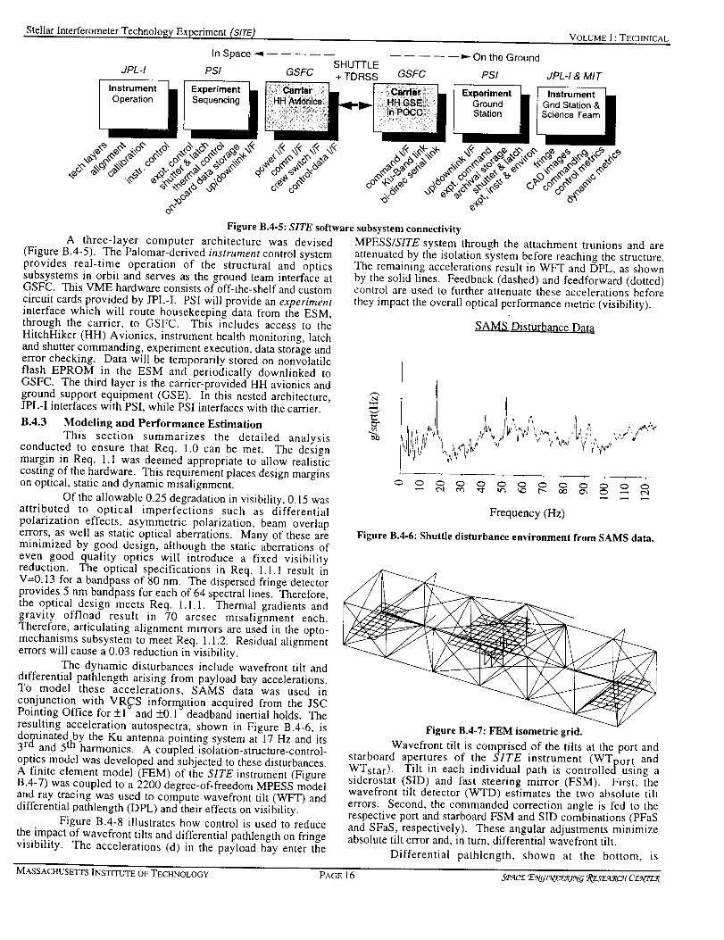
Stellar Interferometer Technology, Experiment (SITE)
In Space -_
JPL-I PSI GSFC
lnstrument _i I Experiment L..
VOLUME ] : TECHNICAL
SHUTTLE+ TDRSS
On the Ground
GSFC PSI JPL-I & MIT
Experiment [,--[ InstrumentI Ground [] /Gnd Station& •
"6': '_ _+@ b'_
Figure B.4-5: SITE software subsystem connectivity
A three-layer computer architecture was devised(Figure B.4-5). The Palomar-derived instrument control systemprovides real-time operation of the structural and opticssubsystems in orbit and serves as the ground team interface atGSFC. This VME hardware consists of off-the-shelf and customcircuit cards provided by JPL-I. PSI will provide an experimentinterface which will route housekeeping data from the ESM,through the carrier, to GSFC. This includes access to theHitchHiker (HH) Avionics, instrument health monitoring, latchand shutter commanding, experiment execution, data storage anderror checking. Data will be temporarily stored on nonvolatileflash EPROM in the ESM and periodically downlinked toGSFC. The third layer is the carrier-provided HH avionics andground support equipment (GSE). In this nested architecture,JPL-I interfaces with PSI, while PSI interfaces with the carrier.
B.4.3 Modeling and Performance EstimationThis section summarizes the detailed analysis
conducted to ensure that Req. 1.0 can be met. The designmargin in Req. 1.1 was deemed appropriate to allow realisticcosting of the hardware. This requirement places design marginson optical, static and dynamic misalignment.
Of the allowable 0.25 degradation in visibility, 0.15 wasattributed to optical imperfections such as differentialpolarization effects, asymmetric polarization, beam overlaperrors, as well as static optical aberrations. Many of these areminimized by good design, although the static aberrations ofeven good quality optics will introduce a fixed visibilityreduction. The optical specifications in Req. 1.l.1 result inV=0.13 for a bandpass of 80 nm. The dispersed fringe detectorprovides 5 nm bandpass for each of 64 spectral lines. Therefore,the optical design meets Req. l.l.1. Thermal gradients andgravity offload result in 70 arcsec misalignment each.Therefore, articulating alignment mirrors are used in the opto-mechanisms subsystem to meet Req. 1.1.2. Residual alignmenterrors will cause a 0.03 reduction in visibility.
The dynamic disturbances include wavefront tilt anddifferential pathlength arising from payload bay accelerations.To model these accelerations, SAMS data was used inconjunction with VR_S inforrn_ation acquired from the JSCPointing Office for +1 and _+0.1- deadband inertial holds. Theresulting acceleration autospectra, shown in Figure B.4-6, isdor, ninated by the Ku antenna pointing system at 17 Hz and its3rd and 5 th harmonics. A coupled isolation-structure-control-optics model was developed and subjected to these disturbances.A finite element model (FEM) of the SITE instrument (FigureB.4-7) was coupled to a 2200 degree-of-freedom MPESS modeland ray tracing was used to compute wavefront tilt (WFT) anddifferential pathlength (DPL) and their effects on visibility.
Figure B.4-8 illustrates how control is used to reducethe impact of wavefront tilts and differential pathlength on fringevisibility. The accelerations (d) in the payload bay enter the
MPESS/SITE system through the attachment trunions and areattenuated by the isolation system before reaching the structure.The remaining accelerations result in WFT and DPL, as shownby the solid lines. Feedback (dashed) and feedforward (dotted)control are used to further attenuate these accelerations beforethey impact the overall optical performance metric (visibility).
SAMS Di_t_rl0ance Data
-_ i )¢
0 0 0 0 0 0 0 0 0 0 0 0 0
Frequency (Hz)
Figure B.4-6: Shuttle disturbance environment from SAMS data.
Figure B.4-7: FEM isometric grid.
Wavefront tilt is comprised of the tilts at the port andstarboard apertures of the SITE instrument (WToort andWTstar). Tilt in each individual path is controlled using asiderostat (SID) and fast steering mirror (FSM). First, thewavefront tilt detector (WTD) estimates the two absolute tilterrors. Second, the commanded correction angle is fed to therespective port and starboard FSM and SID combinations (PFaSand SFaS, respectively). These angular adjustments minimizeabsolute tilt error and, in turn, differential wavefront tilt.
Differential pathlength, shown at the bottom, is
MASSACHUSETTS INSTITUTE OF TECHNOLOGY PAGE 16 S,eac-_ EeC_ffte('_,_cff _X.er__c_CE_Wr-,_

Stellar lnterferometer Technology Experiment (SIRE)
composed of internal (DPLint) and external (DPLext) DPLerrors. First, the internal laser metrology is used to minimizeDPLint. Second, the total DPL is estimated by the fringedetector (FD) and fed to the ODL to minimize total DPL. Notethat the bandwidth with which WTD and FD can be fed back isproportional to the brightness of the stellar target and the amountof science light diverted to these detectors. At low frequencies,the wavefront tilt control system acts as a star tracker. Bymeasuring the angle between the baseline and the line-of-sight,DPLex t can be estimated. At higher frequencies (whichencompass the flexible modes in the system), accelerometersplaced at each siderostat are used to estimate DPLex t. Theselow and high frequency estimates are combined and fed forwardto slew the ODL. This corresponds to disturbance feedforward.
"port I I fsra
"_ t I t J ..... --O
_f_ .._m_ • r
I ..... _ wavefront t_lt eonta'ol
d _1
;- ..... _ ...... _ ..... _ pat_ler_th control
Figure B.4-8: The MTE control block diagram
Figure B.4-9 summarizes the visibility reduction causedby optical, static and dynamic misalignments. These reductionsare shown for three stellar magnitudes and for vibrationsuppression (damping) and isolation present. In the 'damping'column, the 0.3% damped truss is actively augmented to achieve3% structural damping. For an my=5 star, vibration suppressionand isolation are enhancing technologies since V=0.86 whenneither are used. For an my=8 star, both technologies are neededto enable visibility measurements in excess of 0.75 and enhanceperformance to as high as V=0.85. Both vibration suppressionand isolation are enabling technologies for an mv=10 star,causing visibility to increase from V=0.08 to 0.67 through theiruse. However, vibration suppression and isolation might have tobe used together with other technology layers to achieve V=0.7.
Allocated 0.25 Visibility Reduction
Mag5 Mag8 Magl0
[] None
• Damping
• Isolation
Figure B.4-9: Estimated visibility reduction using severaltechnology layers.
VOLUME ] : TECHNICAL
This integrated model used in this analysis will evolvethroughout the program. MIT's finite element model, whichcaptures dynamics, thermal, control, and gravity effects, will becombined with JPL's IMOS optical model. MIT's prototypetruss (acquired in Phase B) will be used to update the static anddynamic portions. The model will track the allocated subsystemerror budgets throughout the design phases and will continuallybe updated as hardware integration progresses.
B.4.4 OperationsThe SITE instrument has three primary operating
modes: calibration, autocollimation (fringe capture with internalstimulus), and operation. In the calibration mode, the Shuttlealigns its IMU using a target star. Simultaneously, thesiderostats acquire the same star to align the instrument line-of-sight (LOS). The error between the IMU and SITE LOS will begiven to JSC pointing operations as a correction factor wheninertially pointing the Shuttle. JSC recommends thiscoalignment procedure, to account for thermal and MPESSmount misalignments, because it helps avoid pointing iterations.
Autocollimation occurs before the6 shutters are openedand consists of rotating the siderostats 45 to retroreflect lightfrom an internal stimulus, located on the beam combining bench,which has propagated through the science light path. Thisprocedure is used to determine the health of the components andalign the optics. It also provides a functional check after eachpre-flight environmental test. Once internal integrity isconfirmed, the siderostats are rotated back, the shutters areopened, and operations are initiated.
The operational mode consists of pointing, acquisition,and tracking of external stellar targets. First, the componenttechnologies are activated and the internal laser metrology isused to slew the ODLs and quiet internal differential pathlength(I rain). Second, the Shuttle is inertially pointed at the selectedstar to +1 accuracy and the SID/CAD pairs capture the staralong their respective LOSs (2 min). Third, beam steeringcontrol shifts to the SID/FSM/WTD combination to zero
wavefront tilt (1 rain). Fourth, the external metrology is fedforward to the ODLs to coarsely zero the DPL after which theODLs begin a scanning operation to hunt for the fringe (1 min).Once found, the fringe-tracking control loop is closed andmeasurements of fringe visibility are acquired in the broad andnarrowband channels (5 min). In total, each stellar observationmade under the operational mode requires about l0 minutes.
B.4.5 Risk ManagementThe identified risks lie in four categories: performance;
design; maturity; and programmatics. There is a performancerisk that Requirement 1.0 cannot be met. In this event, the SITEinstrument allows observations of mv = 5.6 and brighter stars.Also, SITE is designed to allow operation during free drift modesof the orbiter. The SITE operations team can also request thatoperations be conducted so as not to conflict with times of highcrew activity, such as exercise periods.
To reduce the risk of major instrument failure prior tolaunch, SITE will be extensively system tested and the hardwarewill simulate fringe capture and tracking of an mv = 8 star. Inthe event of a failure, SITE is equipped with active means toadjust instrument alignment, can operate in a star tracking modewith either optics arm separately, has means for diagnosingfailure, and can still achieve major subsystem objectives.
The design risks specifically associated with flighthardware development are controlled through a series of stepsspanning the entire program. First, the SERC-funded opticsbreadboard, along with select prototype hardware, will be usedto recategorize all risk = 4 components prior to CDR. This alsoallows early identification of design flaws as well as long-leadprocurement items, thus holding delays to a minimum. Second,
MASSACHUSETI'S INSTITUTE OF TECHNOLOGY PAGE 17 S,_'acz E_t_.__/N0" RL_'.r._.c'-¢¢C'_..__
Stellar lnterferometer TechnoloE_, Experiment (SITE_
the hardware design wilt be placed under configuration controlimmediately following CDR. Subsequent changes to the designwill be subject to guidelines in the SITE configuration changepolicy. Third, after fabrication is completed, the hardware willundergo acceptance tests under the direction of MIT SERC, aswell as all certification tests required to comply with SSPinterface requirements and safety policy. Fourth, Palomar-derived software will be maintained in a configuration-controlledstate through all phases of development and operation. Incombination with the extensive spaceflight experience of theproject team, the procedures described in this section will serveto minimize design risks and ensure successful achievement ofSITE program objectives.
Maturity risk must be mitigated to the level appropriatefor a NASA Class D flight experiment. To this end, SITE drawsupon over 100 person years of research, development, andoperation experience in interferometry by the team members.JPL-I's work on the MARK III interferometer on Nit. Wilson,ASEPS-0 program to build the Palotnar and KeckInterterometers, and the design studies for OSI, SONATA, and alunar surface intert'erometer are complemented by JPL-C's andMIT SERC's technology testbeds.
Programmatic risks are those which impact cost andschedule and include the detail of the design used for costing andscheduling, the maturity of the WBS, the availability of flightqualified hardware versus custom design, and ease of carrierintegration and manifesting. The design involved a detailedanalysis of system performance using Shuttle pointinginformation from JSC, MPESS specifications from GSFC,SAMS data, and NASTRAN and IMOS modeling tools. Thiseffort included a detailed equipment list with componentconnectivity layouts and risk categorization. Margins,appropriate for a conceptual design, have been levied. The sixthlevel WBS, summarized in Part C, assigns high levelresponsibilities and deliverables to the team members mostexperienced for the task. Launch/landing load alleviation in theisolator latches is viewed as the most cost-effective means forreducing survivability risk and maximizing the use o1" off-the-shelf components. Finally, ensured instrument containment,without violating the payload bay door closure envelope, ispreferable over component-level, carrier-required analyses andsoftware certification. The one programmatic risk which is notunder the team's control is manifesting, for which a work aroundplan must be developed. Otherwise, the team has conducted twocost and schedule rounds, along with a JPL Red Team Review,to ensure that the budget is realistic and attainable.
PART C WORK BREAKDOWN
STRUCTURE
Figure C-I shows the Work Breakdown Structure(WBS) for the SITE program detailed through level 4. A fifthand sixth level were developed to assist in developing theResources Plan. Notice that the tasks under WBS-3.0correspond to the subsystems described in Section B.4. "['heschedule and task descriptions have a one-to-one correspondenceto this WBS.
PART D SCHEDULE PLANNING
D.1 SCHEDULE PLANNING
Figures D-I and D-2 show the Phase B and C/Dschedules, respectively. In both, most management and systemengineering tasks permeate the entire program and are thereforenot listed. Instead, the top portion of each schedule shows keyprogram milestones. Care has been taken to maintain a one-to-one association with the tasks listed in the WBS.
VOLLrME I : TECHNICAL
D.2 TASK DESCRIPTIONS
Management (1.0): Management tasks permeate theentire program. For example, planning, scheduling and trackingare continuously conducted for technical as well as financialactivities. The PI organization (SERC) conducts weeklyvideocons with JPL and meetings with SERC team members andPSI. As shown in Task 1. I, these weekly interchanges are usedto identify progress with respect to the implementation plandeveloped in Phase A and the schedule. When problems arise, itis SERC's responsibility to develop work-around plans.Problems which could have major impact on program resources.such as launch slip, will have plans developed in advance.
Financial planning and tracking of the program occursin WBS Task 1.2 on a weekly basis. Actual and accruedexpenses are tracked with respect to the budget and forecasts offunding authorization are updated and reported to the ProgramMonitor to avoid financial resource shortfalls at program criticaltimes such as flight hardware procurement. Since both MITSERC and JPL receive funding directly from In-Step, it isparticularly important that contract modifications for bothinstitutions are coordinated and communicated. Forecasts ofboth overruns and underruns in excess of $100,000 (approx. 1%of the program) will be immediately reported to the programmonitor in Task 1.3.1. Similar financial and technical
management activities are conducted at JPL and PSI (1.4).
Discrete event Phase B management activities includereviews, such as the Conceptual Design Review (CoDR) andRequirements Review (RR), and the formation of the ScienceAdvisory Committee (SAC). The SAC will be partiallycomprised of the Stellar lnterferometry in Space Working Group(SISWG) and allows the SITE team to maintain programtraceability to the larger NASA programs in interferometry.Interaction with the Commercial Industrial Review Committee is
conducted under this task. Technical and financial tracking andforecasting are continued in Phase C/D. Additional reviewsinclude the Critical Design Review (CDR); the Flight ReadinessReview; and Post Mission Experiment Review (PMER).
System Engineering (2.0): System Engineeringincludes tasks which permeate all aspects of the program. Forexample, Requirements (2. I) includes revision of the ERDdeveloped in Phase A and its flow down to the requirementslevied on the subsystem leaders in 2.1.2. Constraints such aspower, volume, mass, downlink, pointing, etc. are quantified in2.3.5. These tasks drive the design tasks in 3.0. Therequirements are frozen at the Requirements Review in Phase B.
Design and Evaluation (2.2) involves engineering taskswhich couple the subsystems; such as detailed modeling, controldesign and performance evaluation to continuously track theability of the system to achieve the program objectives.Development occurred in Phase A, refinement is a Phase B taskand maintenance occurs in Phase C/D when ConfigurationControl (2.3) takes over to ensure that delivered subsystemsmeet their resource allocation and interface requirements.
An important Phase B task is Technical RiskManagement (2.4). A detailed equipment list was developedduring Phase A with each critical component categorized. Thecriticality of component functionality and launch survivability toprogram success demands that category (4) components bcrecategorized through analysis and test prior to CDR. Finally,Program Reviews (2.5) encompasses preparation and support ofall major desi_,n._ reviews.
Subsystem Design & Fabrication (3.0): "l-his taskcomprises the design and procurement of all of the SITEsubsystems. Notice that Software (3.6) and Ground SupportEquipment (3.7) are high level tasks because of the softwarecomplexity and rcaltime flight operations conducted at GSFC,
MASSACHUSETTS INSTITUTE OF TECHNOLOGY P.\GE 18 5,e.qc£'E.\q_:V£,rz_q '&L;.r_.ve_vtFE&,rL<

Stellar Interferometer Technology Experiment (SITE) VOLU,XIEl: TECHNICAL
SITE
1.0 MANAGEMENT
1.1 Planning, Schedule & Tracking1.1.10rqanization and Meetings1.1,2 Schedule Maintenance
1.1.3 Implementation Plan1,1.4 Work-Around Plans
1,1.5 Monitoring & Tracking1.1.6 WBS maintenance
1.2 Financial
1.2.1 Budget Update & Forecast1.2,2 Subcontract Monitoring
1.3 Customer Interface
1.3.1 Program Monitor1.3.2 Science Advisory Comm.1.3.3 Comm. Indust Review Comm.
1.4 JPL & PSI Internal Mgmt1.4.1 Planning & Schedule1.4.2 Technical & Task Tracking
1.5 Quality1,5.1 Quality Program Plan1.5.2 Nonconformance Tracking
2.0 SYSTEM ENGINEERING
2.1 Requirements2.1,1 Expt Req Document2.1.2 Subsystem Reg. Docs.
2.2 Design and Evaluation2.2.1 System Architecture Defn2.2.2 FEM & Loads Analyses2.2.3 IMOS Model & Perf. Eval
2.3 Configuration Control2.3.1 Design Documenls2.3.2 Define Subsystem Interfaces2.3.3 Subsystem Accept, Criteria2.3.4 System Acceptance Criteria2.3.5 System Budgets/Allocations
2.4 Technical Risk Management2.4.1 Equipment list update2.4.2 Make/buy Categorization2.4.3 Testing. Anal. & Vendor Eval
2.5 Program Reviews2.5.1 Design Reviews2.5.2 Requirements Review2.5.3 Non-Advocate Review
2.5.4 Flight Readiness Review2.5.5 Post-Mission Expt Review
Figure C-l: SITE Work
respectively. Phase B involves the finalization of the conceptualdesign and conduct of the preliminary design. The primaryresponsibilities for these subsystems arc shown in Figure D-3.However, this does not imply that there is no involvement byother team members. For example, JPL-[ provides a significantportion of the flight software, even though PSI has ultimateresponsibility for delivering the flight system software. In theResources Plan, a budget for prototyping critical structural,isolation, and optical components has been allocated in Phase B.
Integration & Testing (4.11): Integration and Testingis comprised of subsystem integration and functional tests;carrier integration; and environmental testing of the flighthardware. Figure D-3 illustrates the hardware flow starting withsubsystem fabrication, through subsystem integration at bothJPL and MIT, and ending at final flight system integration atPSI. Most of these tasks occur in Phase C/D with the exceptionof the Form 1628 and Customer Payload Requirements (CPR)Submittal (4.3.1); and the Phase 0/I Safety Review (4.3.3). Form1628 provides NASA HQ's authorization to initiate contact withthe Shuttle integration organizations at JSC and GSFC (MPESSHitchHiker). It is imperative that this submittal occur at thebeginning of Phase B since all carrier integration tasks start atthis point and drive the duration of the program. The CustomerPayload Requirements document is the governing document forall HitchHiker payloads listing requirements, design, integration,and safety subsystems. An initial version of this will becompleted during Phase B and modified in subsequent phases as
3.0 SUBSYSTEM DESIGN & FAB.
3.1 Structure3.1.1 MPESS Interface3.1.2 Precision Truss
3,1.3 Vibration Suppression3,1.4 Thermal Control
3.1 5 Containment & Shutters
3.2 Isolation3.2.1 On-Orbit Isolation3,2.2 Launch Latches
3.30pto-Mechanisms
3.3.1 Pointing Control Subsystem3.3.20DL Mechanism & Servo3,33 Alignment Mechnisms3.3.4 Inertial Feedforward
3.3.5 Mounting Plates. Attach HAN
3.4 Optics and Metrology3,4.1 Fixed Optics & Mounts
3.4,2 Beam Combining Subsystem3.4.3 internal Pathlength Metrology3.4.4 Detectors & Camera Heads3.4.5 internal Stimulus
3.5 Support Electronics3.5.1 Experiment Control Comp.3.5.2 Instrument Control Comp.
3.5.3 Signal Conditioning Syst.3,5.4 Signal Amplifier System3.5.5 Containment
3.5.6 Power Distribution System3.5.7 Data Handling & Storage Sys.3.5.8 Metrology Laser Source
3.6 SoftWare
3.6.1 Experiment Control3.62 Instrument Control3,6.3 Crew Interface3.6.4 Experiment Ground Station3,6.5 Instr. Grnd Station (Control)3,6.6 Instr. Grnd Station (,Anal.)
3.7 Ground Support Equipment3,7.1 Shipping & Test3.72 Ground Station3.7.3 Pseudostar
4.0 INTEGRATION & VALIDATION !
4.1 Instru Subsystem Integ4.1.1 Pointing benches at JPL4.1.2 Phasing interferometer at JPL4.1,3 Structure & Isolation at MIT
4.2 Flight Model Inteqration4.2.1 Tnteg Planning& Doc4.2.2 Test Planning & Doc4,2.3 Subsys Accept/Cert Testing4.2.4 System Integration42.5 Functional TestingJCharact42.6 System Accept/Cert Testing
4.3 Carrier Integration4.3.1 Form 162"8 & CPR Submittal
4.3.2 Integ Reviews (CIR, FOR,,..)4.3.3 Safety Reviews (0, I, I1. Ill)4.3.4 Payload Lnteg P_an/Annexes4.3.5 Interface Control Doc (ICD)
4.3.6 Crew Training4.3.7 JSC & GSFC Interface4.3.8 Material Lists
l 4.3.9 Packing & Stowage PIans
5.0 OPERATIONS
5.1 On-Orbit Procedures
5.1.1 Diagnostics & error id5.1.2 Alignment5.1.3 Protocal format
5.1.4 Carrier pointing procedures
5.2 GSFC JSC & KSC
5.2.1 FM Delivery & Recovery5.2.2 Mission Science Support5.2.3 Mission Control Support5.2.4 On-Orbit Predictions Doc.
5.3 Post-Flight Data Analysis5.3.1 Archiving5.3.2 Perf Analysis wrt Objectives
5,3.3 Perf Analysis wrt Cust. Needs5.3.4 Reportinq & Dissemination
Breakdown Structure
the design matures. The Phase 0/[ Safety Review is the first stepin carrier integration and identifies the safety critical systems aswell as plans for resolution supplied to the carrier's safety office.
Operations (5.0): Operations are Phase C/D activitieswhich define how the experiment will be operated on orbit (5.1)and from the ground through the SITE POCC at GSFC (5.2).Chronologically, on-orbit procedures development occursconcurrently with flight model integration (4.2). Task 5.2corresponds to the conduct of the mission by the SITE operationsand science teams at GSFC and JSC. Task 5.3 captures anddisseminates the flight results to the user community. Thisinvolves development of the design guide illustrated in FigureB.2-1 which quantifies the measured visibility for a given stellarmagnitude as a function of technology layering and disturbanceenvironment. Technology layer performance will be reported interms of both incremental impact and measured visibility as wellas improvement in its respective technology metric (e.g.,transmissivity for isolation). Equally important is the assessmentof pre-flight model accuracy. Flight measurements will becompared with these models to develop a measure of modeluncertainty which provides bounds for future mission modelingefforts. Dissemination occurs primarily through the ScienceAdvisory Committee. MIT SERC will transfer the technologyand experience gained by conducting a short course based uponSITE, developing a Mosaic page for rapid data dissemination,presenting at technical conferences, and publishing journalarticles,
MASSACHUSETTS INSTITUTE OF TECHNOLOGY PAGE 19 S'Pq('E 'E:\%:L_:L'L_/_¢; '_'£.¢'L':I'_2_/O£:_I7Z_

Stellar lntcrt-erometer Technology Experiment (SITE)
PART E MANAGEMENT PLAN
E.1 PROJECT ORGANIZATION AND MANAGEMENTAPPROACH
The MIT Space Engineering Research Center (SERC)and the NASA Jet Propulsion Laboratory (JPL) have assembleda project team prepared to maximize the probability ofexperiment success, to minimize development risks, and ensurecompliance with all the appropriate NASA Space ShuttleProgram (SSP) safety, integration, and certificationrequirements. This team stands ready to successfully completethe SITE project on time, on budget, and with the highestpossible scientific standards. SERC and JPL provide technicaland scientific leadership to the team, while the MIT Center forSpace Research (CSR) provides financial and administrativemanagement. The primary subcontractor, Payload Systems Inc.(PSI), is a small business with an extensive background inmanned spaceflight experiments. PSI will fabricate the hardwarefor SITE as proposed herein (with some major components beingprocured by JPL), and will be responsible for all experimentintegration tasks. The MIT/PSI team is identical to thatassembled to perform MODE-I, MACE, and MODE-Reflight,and, with the addition of JPL, will perform SITE with the samesuperior standards exhibited by those projects.
Fiscal Year 1995 i Fiscal Year 1996WBS Element ,'""'_-""','-'""_'"-",'""':'"'',""' .-'"'"-.' ........... "_"-"', .....
_M _ J i J i A i S :0 -_ N _ D _ d -_ F iM :" A
P_,,,_B i : i i i i i : : : i i................ii ...........
['_"t_:_ t'i_ _ "it'_;][gst'°n'e s' '{'_'[3 i ........ i_'"'':i .................,_ ]_""_"'""_"""'i::" . i....... :_'_has;'O}i": : . .....
t_;;r+_a'_'_'e,r+ii_'('i:_i............'"'r'"_/'_"_;"_'/(U""'+. . .: _.......:'"'"r'"'i'""Ti: ......._:6_iZ_'C__Y._fi-lg&:iiii_............i"'"'_'""T'""i'"''"'"'i'"""'""'.-" ........-:'"'".-".......!'""" .....
: : : : : : : : : : : :.................................................i ......_-....¢......._......'#.....-1 ......_..-...c ....... _.....o......_..-*.e .....
....!:*=.2%?YE...................L..& -. ..L.7. .J i J....... ....22 Design & Evaluation i _! ! i _ i i
................................................. i.,...._...-.*...-..*...-.4-.....L....4..-..< ....... _......_......i.....$ ....2.3 Configuration Control : : ..........• il_"_ i i i i i i i
.... ................ .......UVV"T .....3.o Su}_system 13_Jgn _ i i i i " .: ! i " i :"
...._"i'_t_all};..........................i'"'"_'""_'""!'"" .v'""!'"'"!'"":........."'""_"'T'"'_
................. ................................ i.....4...-.o...-..i......i.......i...-.4.....i ....... i.....,_ ....... i....*._ .....321solatmn i J_ : :. :. :. :. _ :. _ i !
................................................. !......_ ....}......._......,......,..... +......._......._ ....._......._......, .....
3.30pto-Mechanisms _ _" _ " _ _ : : : '7 i :"................................................. i......_....._......i...-._....-..i.....4.....i ....... L,...o......L,...$ .....
3.4 Optics & Metrology : _ : : : : : : : 1_ _ :"................................................ i ............ ,_......L....,¢......i......i....._ ....... L...._......L....,_ .....
3.5 Support Electronics ! ! _i _ _ i i................................................. i......i....."_-.....i...:.6......i......_...- _....... _.....*......i.....$ .....
....i"_'_'g_".................................i......i........................ ,......_.........................................:...........................................i......i.....L....i......L....L....t.....J.......L...J.......i.....,t.....4.0 Integ & Validation i i i _ i i i i i i i i
4.2 Fhg[qt _odel integration : : : _ : : : _ _ ii i i--- ! : : : :---. : :
....a'_e'a_a;+l_r+_;_ioa...........i U i_ ;il d;V i_aa2:ia;; i;/iUY.....
............................................... i......L.... _.--;=....3..... &......i .....&.-m.._.......i..... :_......L....,_ .....g.o _tiorm i _ i i _ : i i i : i
: : : : : : : : : : : :
.... i :Uii i i....... .....Figure D-l: Phase B Schedule
Responsibilities for the SITE project are divided intofive major categories: project management;systemsengineering, mechanisms and isolation, optical benches andsoftware; and flight systems and integration. These latter fourare further broken down as shown in Figure E.I-1 below.Project Management is divided into management and fiscalcontrol. Quality, though performed at Payload Systems, reportsdirectly to the SITE PI, thereby providing independent qualitycontrol oversight. Also shown on the figure are interfaces withNASA project management and integration staff, as well as thetwo SITE advisory committees.
Project Management includes fiscal management, sub-
VOLUME l : TECHNICAL
contractor oversight, administration, performance assurance, andconfiguration control. Activities include financial reporting,contract negotiation, and certification of acceptance procedures.This task is the primary responsibility of MIT SERC, withadministrative support from the experienced team at MIT CSR,and is the direct responsibility of the Co-PI/Project Manager.
Systems Engineering encompasses all SITE researchactivities both in the laboratory and in space. These activitiesinclude ground studies, flight procedures development, scienceoperations during the flight, and postflight data analysis andreporting. These activities will be both managed and performedwithin SERC under the direction of the PI and Co-PI. They areassisted by SERC support staff and faculty, as well as graduateand undergraduate students.
Mechanisms and Isolation encompasses thedevelopment of the isolation system, the optical mechanisms,and the IMOS modeling of the structure. Since much of this willbe directly derived from the experience obtained from the MPItestbed, JPL will be responsible for these tasks. JPL will alsoassist in the integration of these systems onto the flight unit.These tasks are the responsibility of the Mechanisms andIsolation Task Manager, assisted by JPL engineering staff.
Optical Benches and Software encompasses thedevelopment and integration of the optics and metrology into asingle functioning system, and the software to control it. Thiswork is directly derived from the extensive ground work that hasalready been performed at JPL. JPL will also assist in theintegration of these systems onto the flight unit. These tasks arethe responsibility of the Optical Benches and Software TaskManager, assisted by JPL scientists and engineering staff.
Flight Systems and Integration include all activitiesnecessary to transform the laboratory-based experiment into afully space-qualified Space Shuttle payload. These includefabrication of the structure, electronics, and mounting systems,as welt as experiment control software and porting of JPL-developed software to the flight computer, and integration of theJPL-fabricated optical benches and isolation systems. Alsoincluded are the integration tasks: schedule, negotiation, andreviews leading to the allocation of Shuttle resources (weight,volume, power, crew time, ground processing, and flightoperations) as well as successful compliance with Shuttle safetyand certification requirements. These activities are theresponsibility of the Hardware Development Engineer and theIntegration Engineer, assisted by other members of the PSIengineering and technical staff, and under the direction of thePSI Project Manager.
E.2 KEY PERSONNEL AND RESPONSIBILITIES
The Principal Investigator for SITE is Prof. Edward F.Crawley, Director of SERC. Dr. Crawley was the PrincipalInvestigator for the MODE and MACE projects. He providesoverall scientific direction for SITE, particularly in scientificrequirement definition and test matrix definition. Dr. Crawley isa world-renowned authority on structural dynamics and control,with over 75 journal and conference publications in the field. Hewill serve as the primary point of contact between the NASAprogram management and the SITE team. Prof. Crawley will bedevoting approximately 20%, and 30% of his time to SITEduring Phase B, and C/D respectively.
The SITE Co-Principal Investigator/Project Manager isDr. David W. Miller, Associate Director of SERC. He isassisted in his management functions by the SITE administrator,responsible for fiscal and sub-contractor management. Dr.Miller will also direct the Systems Engineering effort, as well asbeing the primary point of contact with the JPL Co-Investigators.He was a Project Scientist on MODE and Co-Investigator onMACE, and is a widely published expert on structural design and
MASSACHUSETrS INSTITUTE OF TECHNOLOGY PAGE 20 S,e.,_c'_T',V6_N_E_ _'_c_ C_+%n_

Stellar Interterometer Trackin_ Experiment (SITE) VOLUME l: TECHNICAL
i Fiscal Year 1996 ! Fiscal Year 1997 " Fiscal Year 1998 ! Fiscal Year 1999 iWBS Element :........ _ ......... :......... :......... ._..................................... .:......... , ......... :................... _...................................... 4 .........
iFQ li FQ 2_FQ 3iFQ 4_FQ liFQ 2_FQ 3i FQ 4!FQ li FQ 2iFQ 3iFQ 4iFQ li FQ 2_FQ 3_FQ 4!FQ 1
Ph..Cm : i i J J i i i J i i i i i i i'__'a'___'R'e'_'ie'_'_"i'_:'_i................:".........................................................................................................................................................................
i C_DR@ i i Readhess .'._ iPMEiR •
Integrahon"_iies_ones"(:/'Si ....... _"........ ".:"......... i ......... ! ......... _............. "L"':T;":a:'i......... !.........i......."XZ"j'a,';'z_:r"i_g_uw_'-7"'Z ........
......................................................_........_..........;........._........._.........._........._.........i........._........._........._.........._......'_...i..._........._...._ ........_.........Distinct Mgmt Events (1.0) _¢AC & _IRC i_ _,C & EIRC i• i SA_ & dIRC•..................................................... _........ _......... s ......... i ......... i.......... _........ _ ......... _......... 2......... (......... _......... a ......... i..._.....i ......... _......... _.......... _.........
2.0 System Engineering i i i i i i i i
...._:_e;i_Y_:oa ......................._ .........i........._..........i........."........._........._.........i.........i.........._.........!.........i_{ .........i....................
............................ _........................ ?........ ?......... ! ......... ! ......... _........ d'_tgn'l_e_'"'! ......... !......... _.......... _.......... ".."......... !......... !......... "........... _........... .."• - •2.a Cortfiguratmn Control . • _ . . _ • _ . ._._. . ,_ • . :
...._ .............................................i........L_i ........._........_i ...................i........._..........i.........i...................i.........i.........._.........• TechRiskMgmt _ i _ i .: ! i _ i _ _ i _ i _ !: : : : : : : : : : : : i i
_:_g_azai_'_'_'ag ........................_..............................i"........_'...............................................................................................................
....s:_'g_au_a ............................_........:.........i _.raau;_ ......._......_ ra_ = ......._........._..........r........._........._........._........._..........".........
....................,.................................i........_.........i.........i....... _........._........_.......dw:¢ .......i.........i........._.........i.........i.........i.........i..........i.........3.2 Isolatmn : : _--a : : aesxgn : _ ¢ .._ : : : : : : : :......................................................i........,_.........i........._........._.........._........_.......,s.......:_ ......._........._.........._.........i.........i.........i........._..........i .........3.30pto-Mechanisms _ " _ design _ A tim q i
...._:_;_a_a;oio7; ...........i........Y_ ........._ ......._......_ _; .......i.........i..........i.........i.........i.........i.........i.........._.........
....................................... :.............. _........ _......... i......... i....... _......... 4................. "......... _......... i......... i......... ._......... i......... i......... _......... i.......... _........3.5 Support Electromcs : : __: : aes_gn : "_ _gb _ ........ "
...................................................... _........ a......... i......... i......... i.......... _....... .'E......... i........ .T......... i......... i......... ,;......... i......... ;......... i......... i.......... _.........
3.6 Software _ i ! _! _ ! " " _ i _ i !l7 i i i_ i --: : x : : : :.... .....................................i.........i.........i.........i .......i......... ......... .......i.........i..........i.........
:i:ii'iiffg//'g911_/ali_;i;.............: .................._........._............................._............................]...............................................................
....iT]:'ih'_ir"g"S'u__y7in_'_..........................._.........:.............................:.............................:.........:......................................................................
.........................................................................i_i .............................i_..._........._.........!........7 .....................................................................4.2 Flight Model Integ _1_ _ _i:inte_: _ testi: 17 i
4_3 Carrier Integ P._ II S ._fety P.kg_ i _1_ Ph I!I Saffty Pk._ :
1_ i Pf i ICD :._} anne'_es !_! C_'_R ' F !b' c'_" w t_rJining:
5.0 Operations . i i ! ! i refirlemen_ i i
..................................................... _ ........ ¢ ......... i......... i...Ae_at....,; ......... i......... i......... _......... i......... a..&.._r_.gi_t.l.h......;. ........ i.......... , .........5.1 On-Orbit Expt Proc i i ! !_i i_=_ i i i i A .m ._ _ _ .:
...................................................... _......... : ......... _......... i......... i.......... i..... ._......... i......... i......... i......... i........ "T:........ "......... i............ m._s_on.ol_ ........
.... .....................................................................................................................................................5.3 Post-Flight A&E
Figure D-2: Phase C/D schedule
Electronics and Software
Deliveryto GSFC
Electronics and Software
Flight Model Inte¢ Functional Testing
._ _ Subsystem Integra6_ _ atatatjpLMITpsI
Figure D-3.: Hardware flow diagram. WBS items are indicated in lower corner.
Certification Testing
MASSACHUSETTS INSTITUTE OF TECHNOLOGY PAGE 21 ,9_'_c'_ To¢_i_._ _&___g:g CE_W_&

Stellar lnterferometer Trackin_ Experiment (S/TE} VOLUME1:TECHNICALStelIar lnterferometer Trackin_ Experiment (S/TE)
ITo NASA Contract Monitor
PrincipalE.F. InvestigatOrcrawley
Project Manager and Co-Principal InvestigatorD. Miller
Administrator
Fiscal Control _11
Center for Space ResearchllJ. Binsack I,
J
M.I.T.
Payload SystemsI Jet Propulsion Laboratory
Figure E.I-I:
Science Advisory Committee ]l
Commercial Industrial Review Committee i
Systems EngineeringD. Miller
Requirements and EvaLT. Vaneck
Data AnalysisT. Hyde
Structural DesignB. Masters
Project organization and responsibilities for SITE.
QuatityR. Rens/law
Flight Systems and tntegratio_J. de Luis
Fright SystemsC. Krebs
Carrier Integ. & Ops.K. Scholla
Ground SystemsS. Pretodous
Test & Verification
E. Bokhour
To NASA
Integration
control, with over 40 journal and conference publications. OnMACE, Dr. Miller was responsible for the control selection anddesign, as well as for ground test operations of the varioushardware elements. As Associate Director for SERC, he haslead the efforts to set up and operate several large groundtestbeds, including the SERC interferometer testbed from whichmuch of the expertise will be drawn from for SITE. Two full-time graduate students will also assist. Dr. Miller will bedevoting approximately 80% of his time to SITE.
Co-Investigators at JPL are Dr. Mike Shao and Dr.Robert Laskin. Dr. Shao is a world recognized authority inoptical interferometry and is the architect of the Mark I, II, and IIground based interferometer instruments. He has authoredpublications in scientific journals and serves as the groupsupervisor of the Spatial Interferometry Group at JPL. Dr.Laskin has served as the CSI task manager since 1991 and hasauthored over 30 journal publications in the field of dynamicsand control of flexible structures. Dr. Shao and Dr. Laskin will
insure the scientific and technological relevance to NASA'sgoals, and will spend 30% of their time on SITE.
Dr. Jeff Yu will be the task manager for the JPL OpticalBenches and Software Task deliverables: optics and metrology,software, electronics, and overall instrument integration. Dr. Yuis an expert in electro-optical systems with several journalpublications and has extensive experience at JPL in systemsengineering and ground based interferometer integration. Dr. Yuwill allocate 100% of time to SITE will be assisted by Dr. MikeColavita and Mr. Brad Hines, each of which have extensiveexperience in the integration of interferometer instruments. Dr.Gary Blackwood will serve as the task manager for the JPLMechanisms and Isolation Task deliverables: isolation, opto-mechanical devices, and IMOS integrated modeling. Dr.Blackwood is an expert in active vibration isolation and groundbased CST testbed experimentation, with several publications inthe field. Dr. Blackwood will spend I00% of his time on SITEand will be assisted by Mr. John O'Brien and Mr. Jim Melodyfrom the CSI program. Key JPL personnel will also be presentat PSI when the flight electronics is integrated with the flightoptics from JPL as well as isolator and structure integration andflight systems integration.
As PSI Project Manager, Dr. Javier de Luis will directthe Flight Systems and Integration effort. As president of PSI,Dr. de Luis has been resonsible for the fabrication andintegration of over a dozen spaceflight experiments over the lastthree years. In addition, he has been the PSI project manager forthe MODE and MACE programs. Ms. Kimberly Scholle will beresponsible for carrier integration and flight operations. She willadditionally serve as the primary interface between the SITEpayload and the SSP integration process. In the past three years,she has succesfully integrated over a half-dozen payloads onnumerous carriers. Flight hardware development is theresponsibility of Mr. Christopher Krebs, PE. Mr. Krebs servedas senior mechanical engineer on the MODE and MACEprojects. Before joining PSI, he designed and integrated severalShuttle payload bay experiments as well as sounding rocketinterferometric payloads for the USAF. These three primaryteam members will be assisted by the PSI engineering staff, allof whom are experienced in designing and flying scientificpayloads in space on several different carriers, including Shuttle,Spacelab, and the Russian Mir space station. PSI's participationwill increase as SITE progresses. Mr. Krebs, and Ms. Schollewill devote approximately 100% and 75% of their time,respectively. Dr. de Luis will allocate 40% of his time to SITE.Additional PSI electrical, mechanical, and software engineerswill provide significant additional manpower support, with over5 full time equivalent engineers working on SITE during itsdesign and manufacturing phases, in addition to the manpoweralready listed.
The project team brings to SITE broad-based andsubstantial experience in manned and unmanned spaceflight.The SITE team realizes the importance of a complete butstreamlined management structure in the successful performanceof flight experiments. Therefore, although the complete SITEteam is not required at the onset of the project, the key membersof the team are already in place and have been working togethersince before the start of Phase A. The members are prepared tocontinue their functions as the project transitions to Phase B.This serves to minimize transition time and development risk,while maximizing the expected scientific return.
MASSACHUSETTS INSTITUTE OF TECHNOLOGY PAGE 22 S_:ac'E 'E_s:k_z'r_t'zf9 5_z"r__c__C'z,%_._

Stellar [nterferometer Trackin._ Experiment (s/r()
E.3 CAPABILITIES, FLIGHT AND EXPERIENCE
The MIT Space Engineering Research Center (MIT)
was formed in 1988 by NASA to serve as a university center of
excellence for research into Controlled Structures Technology
(CST), in recognition of its extensive laboratory experience and
the leading role MIT has played in developing CST. SERC
designed the highly successful MODE experiment, which flew
on STS-48 in September, 1991, and again on STS-62 in March.1994. It is now completing development of the MACE
experiment, scheduled for launch on STS-67 in March, 1995.
The MIT Space Systems Laboratory, from which SERC wascreated, has been involved in numerous flight experiments, most
prominently the EASE experiment, which flew in the Shuttle
payload bay in 1985.
The MIT Center for Space Research (MIT CSR) is
an interdisciplinary organization within the MIT School of
Science which draws faculty and research staff from a variety of
MIT academic departments and disciplines to conduct
experimental and theoretical space-based research. Major CSR
accomplishments include the entire scientific payload for the X-
ray satellite SAS-3, the Voyager Plasma Science Experiment,
and flight experiments on SL-I, D-I and SLS 1 & 2. Current
activities include several AXAF spectrometry instruments and
development and launch of its own satellite for the High Energy
Transient Experiment.
Payload Systems Inc. (PSI) is a small business based
in Massachusetts. Founded in 1984 to provide science and
engineering services for spaceflight experiments, PSI has an
outstanding history of supporting US and foreign investigators in
transitioning from ground-based to space-based research. They
are a leader in providing low-cost, high quality experiments to
In-Step and other NASA flight projects. PSI was selected as theprimary subcontractor because of their excellent performance onMODE, as well as related experience on other manned
spaceflight experiments, including STS-9 and Atlas-1 (for which
PSI provided a Payload Specialist), the STS-51D OcularCounter-rolling Experiment, the STS-61A (D-l) Vestibuhtr
Schlitten Experiment, the IML-1 Mental Workload and
Vestibular Investigations Experiments, and MACE.
The JPL Spatial lnterferometry Group (JPL-I),which moved to JPL in 1989, has built the Mark III
Interferometer on Mt. Wilson which, since 1986, has been in use
by NRL, USNO, and JPL and is responsible for more scientific
results than any other long baseline optical/IR interferometer.Current activities include the construction of the technology
testbed for the Keck interferometer and a mission/systems study
for a space interferometer (OSI) as well as ultra-precise
(picometer level) laser metrology, stabilized (<t0 -10) solid state
lasers, development and use of optical diffraction propagationcodes (e.g., to measure the spherical aberration of the HST), and
conduct of astrophysics research with long baselineinterferometers.
The JPL Control Structure/Interaction Program
(JPL-C) was formed in 1988 and has, at a funding level of
approximately $3M/year, been developing technology for future
NASA missions requiring micron and sub-micron regime
dynamic stability. The CSI team has extensive experience in the
construction and operation of large precision structure groundtestbeds. It has also developed component hardware, such as
isolation systems active members and delay line optics, and
modeling/design software for demonstration on these testbeds.Actuator hardware derived from the CSI active member has been
flight qualified and is currently flying as part of the WF/PC-2
instrument on the Hubble Space Telescope. In another flight
project application, the CSI developed Controlled Optics
Modeling Package software was utilized in deriving the faulty
VOLUME l : TECHNICAL
HST's mirror prescription so that corrective optics could be
incorporated.
E.4 INSTITUTIONAL SUPPORT
E.4.1 Organizational Commitment
The SITE project is of vital importance to bdlT and
SERC as a logical continuation of the research effort begun by
previous SERC spaceflight experiments (MODE, MACE,MODE-Reflight) and as a key element in the ongoing CST
development effort. Furthermore. SITE will provide an
educational focus as well as unparalleled motivation and
research experience for undergraduate and graduate engineering
students completing their studies at SERC. Over the last several
years, MIT SERC has focused significant funds and resources on
the development of a ground-based interferometric testbed.
Results from this effort support directly the current proposal
The importance of SITE is evidenced by the participation of theDirector and Associate Director of SERC as Co-Pls. Their
participation assures that SITE will have high visibility withinthe Center and will be able to draw upon facility resources as
necessary. Financially, Prof. Crawley's contribution as PI during
the academic year is made at no direct cost to SITE.
Additionally, MIT SERC will provide laboratory test equipment,
low frequency suspension systems, and over 3000 square ['eel of
laboratory space to SITE.
At Payload Systems, Dr. de Luis will act as the PSI
SITE Project Manager. As president of PSI, his participation on
the SITE team will provide the highest level of corporate support
and commitment to this project.
JPL regards space optical interferometry as one of its
long term areas for future mission development. The Laboratory
brought Dr. Shao's interferometry group to JPL in 1989 from
SAO, and has committed significant institutional resources
towards the development of ground based interferometry and
studies of space based interferometry. JPL commits Dr. Shao,
the Laboratory's foremost interfcrometry expert, and Dr. Laskin.
CSI task manager, as co-investigators of SITE. Perhaps most
importantly, those JPL personnel who developed and integratedthe Palomar interterometcr and MP[ testbed will be made
available for SITE. The CSI group has committed 1.5 work-
vears of in-kind labor to the integrated modeling activity within
MIT's system engineering task. In addition, the JPL CSI
program is supporting four graduate students at MIT over the
duration of the SITE program.
JPL as an institution is committed to the development
of small Class D experiments on schedule and at low cost. The
JPL Cryo-System In-Step Experiment aboard STS-63 in
February 1995 was 100% successful in meeting its objectivesand schedule, and was within 14% of original cost estimate. JPL
regards In-Step as an important element in the recent laboratoryfocus on the smaller, less expensive science tnissions that will
comprise the New Millenium program for which JPL has been
designated lead NASA center.
E.4.2 Facilities and Equipment
MIT SERC is a fully functional, state-of-the-art
dynamic testing and control laboratory. It has available several
real-time control computers (AC 100, VME-based system),structural ID facilities (Tektronix), and computing facilities
(Sun, Cray). The MIT ASTROVAC facility is also available for
vacuum testing. MIT has developed, under SERC funding, afully functional ground-based interferometer test-bed on which
much of the technology to be used in SITE has been developed.
In particular, optical equipment and laser metrology systems will
be made available to the SITE project. MIT SERC also has
developed several software tools and codes that will be useful to
SITE, including control-design and structural ID software
packages that have been used for MODE and MACE. Finally,
MASSACHUSETTS INSTITUTE OF TECHNOLOGY PAGE 23 _9/'.qoE 'E.N(ilNIE'F2._J_; _&';'g:l'-_(-_t O£.\'/'r'q

Stellar Interferometer Tracki%z Experiment (SIT6)
the active suspension system developed for MACE will also beavailable for SITE testing.
JPL provides state of the art optics test and integrationfacilities, including clean optics space, in the new ObservationalInstruments Laboratory. The Dynamics Laboratory and MPITestbed facility offer extensive dynamic test equipment forcomponent characterization and control implementation,including a VME real time computer. JPL also providesextensive environmental test chambers: acoustic, vibration.static, and thermal/vacuum. The Molecular ContaminationInstrument Facility is available for outgassing characterization.
Payload Systems has a 10,000 class clean-room facilitydedicated to assembly and testing of spaceflight hardware, whichis particularly important for the optics. Directly adjacent to thespaceflight hardware assembly room is an electronics and non-flight hardware assembly and checkout laboratory. PSI also hastwo Anvil CAD facilities dedicated to spaceflight hardwaredesign tasks. Locked, limited access archive facilities areavailable for controlled drawings and documents. All itemsprocured for flight hardware fabrication are tracked on asoftware platform developed specifically for that purpose by PSI.Other facilities of interest include a configuration-controlledsoftware development suite on dedicated PCs. For SITE,Payload Systems will procure a portable, Class 1000 clean roomfor assembly and handling of all optical equipment.
For budgeting purposes, vibration and thermal testinghas been assumed to be conducted at the Langley ResearchCenter facilities, charged at the standard non-NASA rates. EMIand offgas testing will be conducted at JSC facilities, as providedin the standard Payload Integration Plan. Availability of thesefacilities is negotiated during the standard integration process.
E.5 MANAGEMENT FUNCTIONS
This section outlines the policies and procedures thatwill be used to ensure successful project completion withoutplacing unreasonable burdens on the project budget andresources.
E.5.1 Science Development ManagementMIT will ensure successful achievement of the SITE
technical goals by verifying that all engineering sciencerequirements are met. This will be accomplished in three stages.First, a formal Experiment Requirements Document (ERD) hasbeen written and baselined; all subsequent technicalrequirements and designs will be derived from it. The ERD andderived documents will be under formal configuration control.Second, the PSI team will participate during the fabrication of allSITE prototype hardware, providing design guidance withregards to flight hardware development and certification issues.This will minimize changes between ground and flightcomponents, and will familiarize the team with the engineeringrequirements and objectives. Third, the PSI SITE ProjectManager, Dr. Javier de Luis, will participate in all engineeringdiscussions and meetings at MIT, serving as a conduit betweenthe engineering science and the flight hardware development.
E.5.2 Development Risk ManagementIn addition to risk minimization methods applied in
project management and experiment integration tasks, the risksspecifically associated with flight hardware development arecontrolled through a series of steps spanning the entire projectschedule. First, the SERC-funded optics breadboard will be usedto identify potential problems before prototype or flighthardware design has commenced. Second, fabrication of certainkey prototype hardware will be concluded prior to the HardwareCritical Design Review, allowing early identification of anydesign flaws and potential solutions as well as long-leadprocurement items necessary for flight hardware fabrication.
VOLUME 1: TECHNICAL
Thus redesign and procurement delays will be held to aminimum. Third, some prototype testing will be completed priorto the Hardware Critical Design Review, so that performanceand environmental data will be available before the detailed
design of the flight hardware is finalized. Fourth, the hardwaredesign will be placed under configuration control immediatelyfollowing CDR. Subsequent changes to the design will besubject to guidelines in the SITE document change policy. Fifth,after fabrication is completed, the hardware will undergoacceptance tests under the direction of MIT SERC, as well as allcertification tests required to comply with SSP interfacerequirements and safety policy. In combination with theextensive spaceflight experience of the project team, theprocedures described in this section will serve to minimizedevelopment risks and ensure successful achievement of SITEproject objectives.
E.5.3 Configuration ManagementConfiguration management is an integral part of
producing high quality products and services which fulfillcustomer requirements. It comprises three activities:identification, control, and status tracking. PSI has developed aSITE Configuration Management Plan describing theimplementation of: Requirements: Design; Acceptance CriteriaSpecification Documents: Development, Certification, andIntegration Plan; Configuration Identification Record(containing a definitive listing of all controlled items and theirlevel of control): Document/Drawing/ Schematic, Hardware,Software, and Change Control (all tracked in respective logs):and Configuration Status Tracking (central log containingrecords of all change requests and their dispositions). These arethe same tools successfully employed in all of PSI's spaceflightprojects, including MODE and MACE, and they serve tominimize nonconformance incidents.
E.5.4 QualityPSI will deliver all SITE hardware, software, and
services in accordance with SITE project qualityassurance/control procedures that are described in the SITEQuality Program Plan, and summarized here: The projectQuality Engineer will ensure that quality concerns (includingsafety, reliability, maintainability, testability, producibility,supportability, and human engineering) are addressed in everyaspect of the project, including project management, hardwaredesign, procurement and fabrication, subsystem and integratedsystem testing, packing and shipping, and final flight readinesspreparation. The Plan is compatible with a Class-D modifiedpayload. It emphasizes prevention of nonconformances throughtotal adherence to documented project requirements and willprovide a comprehensive approach to detecting, documenting,and resolving nonconformances, with emphasis on preventingtheir recurrence. In support of the Plan, PSI will implementInventory, Procurement, Fabrication, Non-Conformance. andTest and Evaluation Controls to ensure that all articles andmaterials procured and produced meet SITE projectrequirements.
The Quality Engineer will review and approve Qualityplans from all major subcontractors delivering hardware andsoftware components to PSI to ensure compatibility with theSITE Quality Program Plan. Since PSI is the integrator of theflight systems, JPL-delivered hardware and software will also berequired to meet the quality standards as specified in the SITEQuality Program Plan.
E.5.5 Integration Documentation and ControlDuring on-orbit operations, the SITE test article will be
located in the payload bay. We have kept the SITE requirementswithin the capabilities provided by the standard HitchHikerinterface. We therefore expect most of our integration
MASSACHUSETI'S INSTITUTE OF TECHNOLOGY PAGE 24 _¢,P:'ICI5 E?,_(iI_E'.FJR.I_ff _ES'E:_:RF'-q (_E._IT_2.(.

Stellar lnterferometer Trackin_ Experiment (SITE)
documentation to be governed by the Customer PayloadRequirements document. By producing meticulous GSFCintegration documentation, we are prepared to support anyadditional documentation requirements that may arise withminimal effort. Our approach will be to initiate productiveinteraction with all appropriate GSFC and JSC integrationpersonnel early in Phase B; the excellent working relationshipbetween PSI and JSC will contribute to the speed and accuracyof this process. All SITE reviews, launch and mission operationswill be supported by appropriate team members at the necessarysites.
In addition to integration documentation and meetings,the SITE team will support the Phase Safety Process. The samephilosophy applied to integration tasks will be applied to safety:the SITE Integration Engineer will establish contact with theappropriate safety personnel immediately following 1628approval. The SITE team will support Phases 0/I through IIISafety Reviews and will prepare exhaustive Safety DataPackages at each phase to minimize the potential for late payloadredesign. This is the same method applied to MODE-I, MODEReflight, and MACE. In all the safety reviews conducted forthese projects, not a single action item was assigned to thepayload organization. In fact, the Payload Safety Review Paneldeemed the MODE Phase II Safety Data Package so complete asto make a Phase II meeting superfluous, and subsequentlycanceled the review. Of course, SITE presents a completelydifferent set of safety concerns than those faced by MODE orMACE. In particular, placement of the interferometer andavionics in the payload bay will necessarily require carefulattention to thermal, EMI, and fracture control. However, fromthe onset, SITE was designed with these issues in mind, hencethe completely enclosed optical platform and avionicscontainers. Our preliminary safety analysis, as well as informalconversations with NASA JSC and GSFC personnel, have notidentified any insurmountable safety critical issues.
E.5.6 Reporting, Meetings, and ReviewsThe success of SITE will depend on excellent
communication both within the team and with external
organizations. To ensure seamless communication within theteam, informal communication lines will be supplemented by arigorous reporting structure. Weekly Project Team Meetingswill be held at MIT will provide the team members with aregular opportunity to discuss task progress and will help toensure early detection and resolution of schedule and technicalproblems. Video conferencing will be used to maximizeinformation exchange with JPL and reduce travel costs.Monthly Telecons with the NASA Program Monitor will beconducted, and will provide the Program Monitor with regulartechnical and financial status updates. The Program Monitorwill also be invited to participate in all other team meetings, athis/her discretion. Monthly Technical and Financial Reports andQuarterly Financial Reports (533 M and 533 Q) will be prepared
VOLUME l: TECHNICAL
by the Co-PIs based on status reports from PSI and submitted tothe NASA Program Monitor. Finally, Scheduled ProjectReviews will include the Requirements Review, ConceptualDesign Review, Preliminary Design Review, Critical DesignReview, Acceptance Review, and Post Mission ExperimentReview as well as Interface Control Document/PayloadIntegration Plan Meeting and Phase Safety Reviews. Supportingmaterials will be provided to the NASA Program Monitor inadvance of each review.
E.5.7 Sub-Contractor ManagementThe PSI SITE Project Manager will report to the Co-PIs
on technical matters at the weekly project team meeting.Financial control of the subcontracts will be handled by the CSR.PSI will submit monthly billing statements and updated costprojections, which the Co-PIs will include in the financialreports submitted to NASA. This is the same organizationalstructure used successfully for the MODE and MACE projects.
E.5.8 Fiscal Control and Procurement
The Center for Space Research will be responsible forfiscal control for SITE. CSR has a long history of flighthardware development for NASA, and has at its disposal thenecessary tools required for sound fiscal control. CSR willprepare and submit Monthly and Quarterly Financial Reports(533M and Q) to NASA. CSR will require PSI and JPL tosubmit similar reports which will also be forwarded to NASA lbrreview. Information from these reports will be used to anticipatecost profiles and funding requirements. PSI and JPL will beresponsible for the purchase of flight hardware components.Their extensive flight hardware experience has resulted in a largenetwork of reliable, experienced suppliers who can deliver on-time and at reasonable cost. For all purchases over $1,000, PSIand JPL will solicit competing bids from multiple suppliers.
E.5.9 Schedule, Budget and TasksThe project schedule shown in Figure D-I and D-2 is
extremely ambitious for the science, technology development,and integration complexity SITE will entail. In recognition ofthis fact, MIT, JPL, and PSI will strictly monitor SITE schedules,budgets, and task progress, to identify and resolve potentialscientific or technical problems at an early stage and withminimum impact to the project. The Co-PI/Project Manager, thePSI Project Manager, and the JPL Task Managers will update theImplementation Plan that will serve as the source document forall management actions for the SITE project. The plan outlinesthe task, schedule, and Resources Plans for Phases B and C/D,along with corresponding controls. The Co-PI/Project Managerwill work with the Project Administrator to track the status of allcontract-related tasks through automatically generated weeklyand monthly accounting reports. PSI and JPL will supplysufficient status information to enable the Co-PI/ProjectManager to monitor the weekly progress of all tlight systems andintegration tasks.
MASSACHUSETI'S INSTITUTE OF TECHNOLOGY PAGE 25 .gP.qc'xE.'_I_!Ez_G PC_'E_'_¢'2(CE_.WE:_

Attachment B: The costs shown in the tame beJow represent all project costs (in thousands) t_olmn om by program phase
(sulxlividcd by Fiscal Year) and WBS elements. MIT and PSI costs have been combined since
pmgramma_cally PSI is a subcontractor to MIT. YPL costs ace shown separately. Only those tasks in which
a SITE parmcr pasticipatcs arc shown in their respective table. Tic last line is a summary of the entire program.
Mff AND B(FY95) B(FY96) I=ham8 C/D(FY96) C/D(FY97) C/O(FYg6) C/O(FYgg) PtmuCR) TOTAL
TOTAL TOTAL (all ph--,,a)
Mrr and PSI Total: 350.8 448.2 799.0 1,047.5 2,241.0 1,472.7 774.8 5,5.36.1 6,335.1
JPL1 Management 7.2 5.4 12.8 110.4 219.3 129.3 18.3 477.3 489.9
1.4 JPL & Subcontractor Management 7.2 5.4 12.6 69.1 94.0 65.5 18.3 246.9 259.5
1.5 Quality 41.3 125.3 63.8 230.4 230.4
2 System Englneedng 10.0 15.0 25.0 40.0 70.0 40.0 150.0 176.0
2.5 Program Reviews 10.0 15.0 25,0 40.0 70.0 40.0 150.0 175.0
3 Design & Fabrlcstlon 245.9 272.9 518.8 2,082.4 1,378.2 3,460.5 3,979.3
3.2 Isolation 41.8 52.1 93.9 299.0 298.7 597.7 691,8
3.30pto-Mechanical Systems 61.7 111.2 172.9 462.6 531.2 993.8 1,166.7
3,4 Optics & Metrology 83,4 67,0 150.4 574.7 457.3 1,032.0 1,182.4
3.5 Support Electronics 37.5 24.0 61.5 452.5 12.1 464.6 626.1
3.6 Software 21.5 18,8 40.1 293.5 78.9 372.4 412.5
4 Integration & Validation + 448.5 599.4 1,048.0 1,048.0
4.1 Subsystem Integration 448.5 488.7 937.2 937.2
4.2 Flight Model Integration 110.8 110.8 110.8
50perstlons 133.8 133.8 133.6
5.1 On-Orblt Experiment Procedures 44.6 44.6 44.6
5.2 GSFC, JSC, & KSC Operations 44.6 44.6 44.6
5.3 Post-FIIgt_t Data Analysis & Evaluation, 44.6 44.6 44.6
JPL Total: 263.1 293.3 556.4 2,232.7 2,115.9 768.8 152.2 6,269.6 5,626.0
TOTAL PROJECT 813.9 741.5 1,355.4 3,280.3 4,357.0 2,241.5 927.0 10,806.7 12,161.1
Uffmd Pm1 Management 60.0 64.9 124.9 94.1 151.0 165.0 105.9 516.0 640.9
1.1 Project Planning & Sc_edute 14.0 17.8 31.6 43+8 65.1 58.3 28.3 195.5 227.2
1.2 Financ_al 18.6 15.3 33.8 10.6 19.0 i 20.2 17.4 67.2 101.0
1.3 Customer Interface 1.7 2.2 3.9 3.8 3.9 I 11.3 7.6 26.6 30.5
1.4 JPL & Sul0contmctor Management 19.2 24.2 43.4 34.0 58.1 58.1 43.7 194.0 237.4
1.5 Quality 6.5 5.6 12.1 1.9 4.9 17.1 8.9 32.7 44.8
2 System Engineering 151.9 115.2 297.1 209.2 291.8 I 126.6 72.6 700.1 967.2
2.1 Requirements 37.9 4.0 42.0 -, 42.0
2.2 Design & Evaluation 43+7 43.4 i 87.1 96.3 139.4 97.9 21.2 354.8 441.9
2.3 Conflgurallon Control 13.6 - 13.8 59.2 67.0 22.5 35.3 184.0 197.6
2.4 Tecttnlcal Risk Management 4.9 4.9 33.2 33.2 ! 38.0
2.5 Program Reviews 58.7 62.9 119.6 20.5 65.5 6.2 16.0 128.2 247,8
3 Design & Fabrlcstlon 120.7 183.7 ; 304.4 625.6 1,409.5 196.8 66.9 2,300.7 2,605.2
3.1 Structure 83.4 104.3 ' 187.7 180.3 412.7 592.9 780.8
3.5 Support Elecl;.onlcs 14.9 51.8 : 66.7 245.1 563.9 809.0 875.8
3.6 Software 22.4 27.8 _ 50.0 67.2 183.4 194.2 24.4 469.2 519.2
3.7 GSE - 133.0 249.5 4.6 42.5 429.6 429.6
4 Integration & Velldstlon 18.2 81.3 99.5 98.8 352.5 926.7 130.0 1,507.9 1,607.4
4.1 Subsystem Integration " i 58.8 95.5 20.3 172.6 172.6
4.2 Flight Model Integration 10.6 10.6 21.3 11.8 29.6 601.9 75.0 718.3 739.8
4.3 Carder Integration 7.5 70.6 78.2 30.2 227.4 304.5 65.0 617.0 695.2
5 Operations 3.1 3.1 19.9 38.2 55.7 399.8 511.4 514.4
5.1 On-Orbit Experiment Procedures 3.1 3.1 3.1 6.5 41.0 15.1 65.6 68.7
5.2 GSFC, JSC, & KSC Operations 16.9 29.7 14.7 318.4 379.6 379.8
5.3 Post-Flight Data Analysis & Evaluation 66.1 66.1 66.1

Z:I
is
i
° i
_N
ILS;Ji _._f
,g
N
E-
, i:i 16 _9o
1
_=_
___
, . , . .'., ....... , . ,I
-_" _
,n
. _ _
,_ ,._0_ _r,,. ' "
. -: ;_
i...i...1=; _o _ .......
....... i ..........
....... I _;' :_-_
_°_''=:__
...... i •
_ :.i __ ' _:i_
__::_
m
_'_ _i
I

CONTRACT PRICING PROPOSAL COVER SHEET
NO[['-: This Iorm _S used in contract actions _f su0missJon of cost or pncm_l data is2. NAME AND ADDRESS OF OFFEROR (Include ZIP Code)
Massachusetts Institute of Technology
77 Massachusetts Avenue
Cambridge, MA 02139
1 SOL_CiTATiON/CONTRACTI'?,_iOOIF]CAT]ONNO
AO W-OAST- 1-92
required. (See I-AH 15.804-6(b))
DUNS: 00-142-5594
TYPE OF CONTRACT (ChecK)
[] CPFF[]{-'-] FPI [] OTHER (Specify)
CPIF [] CPAF
Cost Reimbursement
3A. NAME AND TITLE OF OFFEROR'S POINT OFCONTACT
Patricia Greer
Coordinator
FORM APPROVEDOMB NO,
9000-0013
38. TELEPHONE NO
(617)253-3864
4. TYPE OF CONTRACT ACTION (Check',
X A, NE'W_ D LETTER CONTRACT
B. _EORDER E. UNPRICED ORDER
C. PRICE REVISION/ F. OTHER (Specify)REDETERMINATION
COST PROFIT/FEE I C TOTAL
$ 0 I $6,335,100A. I B.$6,335,100
PLACE{S)ANDPERIOD(S)OF PERFORMANCE
Massachusetts Institute of Technology, Department of
Cambridge, MA 021398. L_st and reference the _lentrfication. quant=ty and total price Dtopose_3 for each contract line Ftern A line ptem cost DfeakOOwrl SuDporhng this recap
Contractlll( _Cont_nue oil reverse Tand then on DJaln Use same head_s._A. LINE I'TEM NO. B. ' IDF.NTIFtCATION C. (_UANTITY
A
See attached proposal
10.
12.
required unless othar',_nse sDe(::fle¢lby the
D. IO1AL I-'HI(..;F" F'. HF.I-
A, WILL THIS CONTRACT ACTION BE SUBJECT TO CASB REGULATIONS?(If "No', explain _nDr_osal)
[] YES [] NO
C HAVE YOU BEEN NOTIFIED THAT YOU ARE OR MAY BE IN NON-COMPLIANCEWITH YOUR DISCLOSURE STATEMENT OR COST ACCOUNTING STANDARDS?(If "Yes', exl_leensn proOosal}
[] YES [] NO
B HAVE YOU SUBMITTED A CASB DISCLOSURE STATEMENT (CASB DS I or 2_?(ff "Yes'. specdy Jn proposal the office to whtcl_ suDmiffed and ff deten'nlned to be
aOequatel
[] YES [] NO TO ONR 7/23/86 (Update in Process)
o IS ANY ASPECT OF THIS PROPOSAL INCONSISTENT WITH YOUR DISCLOSEDPRACTICES OR APPLICABLE COST ACCOUNTING STANDARDS':'(If "Yes" etq_a_n _nproposal}
[] YES [] NO
15
17 SIGNATU RE/._,_ .
NSN 7540-01-142-9645 / / • / 141%102"US GPO: 1987-181-247-6015
This proposal is suOmdtea in response to the RFP contract, modification etc in I|em 1 anti reflects our 0est estimates and/or actual costs as of Ibis date and conforms w_h _e Instructionsn FAR 5 804-6(b 2), Table 15-2 By suOmitting this proposal, the offeror rfsetected for negotiation, grants the contracting officer or an authorized reorese_, tatlve the nght to exa,rnJne a,tanytwne before aware3, those books, records, documen s and other types o factual information, regarclless Of form Of wh.eltler such SUDportlng nformat on s sgecffwJitly referenced or ,nc uOed in he
proposal as the I:)as=sfor pncinql that will permit an aOequate evaluatKx_ of the proposed pnceNAME AND TITLE(Type) 16.
David J. Harrigan
Associate Director
NAME OF FIRM
Massachusetts, nstitut e Dis TeChEn OoIFOsCJuI_MISSION
STANDARD FORM'14.1] (REV 7-571
PrescrV_ed by GSAFAR 14.8CFR I 53.215-21cl
[] YES [] NO
HAVE YOU BEEN AWARDED ANY CONTRACTS OR SUBCONTRACTS FOR THESAME OR SIMILAR ITEMS WITHIN THE PAST 3 YEARS?ll "Yes" identify xtem(s), cust_ner(s) and contract nurnDer(s))x(
[] YES r-_ NO
9. PHOVIDE NAMF.. AI]DHF.,..%S AND TELFºPHONE NUMBEH [--L I THE: FOLLOWING ava#aOle)
CONTRACT ADMINISTRATION OFFICE B. AUDIT OFFICE
Office of Naval Research Defense Contract Audit Agency (DCAA)495 Summer Street, Room 103 238 Main Street, Suite 311
Boston, MA 02210-2109 Cambridge, MA 02142
(617) 451-4666 Mr. George Kilbride (617) 252-1028 Mr. Paul Catanzano
WILL YOU REQUIRE THE USE OF ANY GOVERNMENT PROPERTY IN THE 11A. DO YOU REQUIRE GOVERNMENT 11B. TYPE OF FINANCING {,/ o_e)PERFORMANCE OF THIS WORK? (If "Yes', xdent#f)4 CONTRACT FINANCING TO PER-
FORM THIS PROPOSED CONTRACT';
(If'Yes*, compteteltem ltB_ [] ADVANCE [--'] PROGRESS
PAYMENTS PAYMENTS
[] YES [] NO _ GUARANTEED LOANS
13. IS THIS PROPOSAL CONSISTENT WITH YOUR ESTABLISHED ESTIMAT]NGAND ACCOUNTING PRACTICES AND PROCEDURES AND FAR PART 31 COSTPRINCIPLES? (If "No'. expia_)
[] YES [] NO
14. COST ACCL)UNTING STANDAHL)S BOARD (CA_B )ATA (PuDtfC Law 91-379 as amended and FAN PAP/F 30)

CONTRACT _ _ COVER SHEEt" 1. SOLICITA_TA_IOOIF1CATIC_ NO. _APPROMED
OMB NO. 3000-0013
NOTE: This form is used In oorgract acllong # submmsion ol co_ or prk:_ dale is requkwd. (See FAR 15.804-6(b,t)
2. NAME AND ADOPr¢SS OF _ (Include ZlP Code) 3A. NAME AND TITLE OF OFFEROf:I_ POINTOF CONTACT
PAYLOAD SYSTEMS/NC,. Pamela A. Moriarty, Controller
270 Third Street
Cambridge, MA 02142
S. TYPE OF CONTRACT
I IOTHER (Specify)
7. PL_E(S)ANDPB_K:)O(S)OFPEFC-ORMAMCE270 T}urd Street, Cambridge, MA 02142
Period of Performance I June 1995 - 31 Dec. 1999 (Phesc_B and C/D)
4. TYPE OF CONTRACT ACTION (Cl_¢k)
X A. NEW CONI"RACT D. LE'rTER _
EL_ORDER E._ORD_
C. PRICE REVISION' F. OTHER (Spec_)
REDETERMINA'rlE_
6. m_oe:_s_ COST {A,S.,C)
A. O06T B. PRC_T/FEE ]C. TOTAL
$ 4,435,644 $ 3992.08 I$ 4)]34,852
3B. TB.ER.K3NE NO.
(617) 868-8086 ext. 19
8. List rand ref_'encl _e k:lentifk_tJon, quanHty and tot=l p_ce pmpo_¢l _ _ contract line item. A line Item _t b_ SUl;C_'Bng this reako I$ re-
quim<l unl_ otherwise speOfled by ti_ Contracting Officer. (ConSrpu#onreve_e_d_onpi_nj )elf ifn_. Uaosameh_c#n_.}
! A. LINE ITEM NO B. ID(B_TIFIGATK_ C. QUANTITY D. TOTAL PRICE E. REF.
001 Payload Systems [nc Proposal No. 92-P028 I Lot 4,834,852 See Attached
entitled:StellarInterferometer Tracking
Experiment (SITE)
9. PROVIDE NAME TADORESS r AND TELEPHONE MJMBER FOR THE FOLLOWING (if ava//ab/e)A. CONTRACT ADMNSTRATION OFFICE
Defence Contract Administration Services
495 Summer Street
Boston, MA 02110 Tel. (617) 451-4180
10.WLL YOU REQUIRE THE USE OF ANY GiOVERMBCr PROPERTY
IN THE PERLE OF THIS WOF_? (if "Yes," identify)
12. HAVE YOU BEEN AWARDED ANY CONTRACTS OR SUBCONTRACTS FOR THE
SAME OR SIMILAR FrEMS wm-IIN THE PAST 3 YEARS?
(if "_'es,"I_t___,/tem(.j,c=to,._.) ,_ _,== ,,,.,n'_,,Vk._lm
14. C_T AC,COONT1M3 STANDARDS BOARD (CAS8) DATAA. WILL THIS CONTRACT ACTK_ BE SUBJECT TO CAS8 REGULA_
(If "No,'explain in proposal)
_]ws ['-]_oC. HAVE YOU BEEN NOTIR ED THAT YOU ARE OR MAY BE IN NONCOMPLIANCE
WTTH YOUR D_SCLO_URE STATEMENT Oft _ _ STANDARDS?
B. AuDrr Ce'FICE
Defence Contract Audit Agency, Boston Branch
Thomas P. O'Neil Federal Building
10 Causeway St.,Rm. 253, Boston, MA02222 Te1.(617)565-7352
11A. DO YOU REQUIRE GOVEFIdE_IT
CON1Tb_CT _IING
TO _ THIS_
(If "Yes," _omplete item I tB)
AND FAR PART 31 CE_T PRINCIPALS? [If "No," eRotain)
. TYPE OF FINANCING (it 0_e)
ADVANCE PAYMENTS
_ PAYMB_1S
GUARANTEED LOANS
Public Law 91.37g as amended and FAR PART30)B. HAVE YOU _ A CAS8 DIISCLO_URE STATEMENT
(CASB DS-1 or 2)? (ff "Yes," speofy m proposal the office to which
submi#ed and tl deCermined to be adequate)
O. IS ANY ASPECT OF THIS PROPO6AL INCONSISI"B_ WITH
YOUR DISCLO6ED PP,/_TICES OFI APPUC,NBI.E COST
(If "Yes, ° explain in propose) _ STANDAFE)S? (If "Yea," e_ain in propoeal}[--I"_
This prolx_ is submi111ed in r_Ipo_ tO the RFP contn_t, modification, elc. in item I _ ¢_ our b_Ist _l_ml_ Imd/o¢ g¢lUlll colt u
of this _,te and ¢onformll _lffi the Insff_ctlons in FAR 15.804_b) (2), Tal_e 15-2. By lu0mltting this I_, [he off_, If Imisc1_l fornegoll_tion, gr_q_, the coning officer o¢ Im au_horlziKl rep¢_,entllthte Itle rlgl_t to examine, g[ arty time l_IfGre Ifle awllr_, _olNl books,re(on:Is, documents mid other type= of factuel Informallon regardleu of form or whether sucfl supportln0 IflformaMon Is spectflcalty ref-erencAido¢ InctuckKI in the pmpo_l == the besis fo_ p_cmg, mat will permil I_ _lequate _=d=m_tt of tt_ proposed prtc_.
15. NAME AND TITLE (Type) 116. N/_k4EOFRRM
Pamela A. Mor_aH_j', Controller I PAYLOAD SYSTEMS INC.
17.7__.j.. _ _=_NSN 7540-01-142-9845
18. DATE OF SUBMI6,SION7 February 1995
II'_&R_ FORM 1411 (REV. 747]
1411-102 I_'em_bed by

r
JO! Pt'_l_ul_(',n L,'ll_rgtory
4!KX,; f)_ _r:_ve L',r,w*JPL
J'anuary 20, L9g5[')TREI'AP.95-027
Pro+.".Edw',_dCrawleyMassachusetts[nsfitut¢or"Teclmo[ogySpaceEngin_,-dngRe.,scarchCenterBuilding 37, Room 35 t77 Massachusctt._ AvenueCambridge, MA 02139
S.b,ie : Letter oi Commitment
Reference: National Aeronautics and Spa_¢ Administration In.Step 'l'¢chnologyExI'_riments Program Solicitation W-CAST-1-92 Phase 8 Proposal: Stellar h_tc'rferometryTechnology Experiment (SrrE), MIT February, 1995
Dear Pro/'. Crawler
The Jet Propulsion Laboratory (JPL) is pieced to convey its intent to participate in ther_tercnccd effoct It is ouc understanding that MFr will submit a propo:',_ for thereferenced eftbct to the Nauonal Aeronautics and Space Administ_,ntiot_.
The proposed ¢x0c.'rin_at ia suitable for a mission on the Space St_uttlu to demo, str_overa;.1 tcc:hnology readit_css for space optical interferomea'y, l'hm will be dolle bydeveloping and tlyir, g, in fl_c Shuttle cargo bay, a 4-m baseline opt_c_ mtert'¢romc_rcapable of acquiring and stabilizing starlight interference fringes at _l_c25 n,nomcter P,MS
1¢v¢l. SiTE will also prtx:lucc on-orbit cng'ineer!,ng data le,'_ding to a qa_mfitativemxlcrslandmg of 1h¢ benefit:; of various layers of controlled sm_cturcs technology (via.,vibra_on isolation, b_gh bandwidth active optical control, "ug! structural vibraUon _mping)[:'orfutur_ space interfcromctry missions. Finally. SItE will serve to flight validatemodeling toots like IMOS ({ntcgrated Modeling of Adv,mced Optical Sys_¢n_) which willbe invaluablc to tl_e ncxt generation of precision space optical systems.
J'PL will, on a bcs_.--cffons 'basis, deliver to M1T or its desisnatcd subconu'actor: (i_ SITEinterferometer instrument flight hardware (i.o., three opticit[ benches populated withoptical, op_n¢chanic;_, and laser metrology compo_czxts comprising the instr,:meat) Forintegration with tt_ SITE sm_ctm'c; (it) SITE isolation system flight hardware; tilt) SITE
instnm_nt control flight software; (iv) SITE isolator engine,ring model; (v) tresssimulators of"the instrument (_tical benches; ('_i) SiTE IMOS mathematical model forpcrforma_me simulation; (vii) relevant design .and test ck_cumentation. IPL will _dso
p_ticipatc in flight data zmalysis anti reporting. "ih¢_ tasks and delivcrai:les, along withtheir positions in the ore.tall SITE WBS, we detailed in the rct'c-r_nced Phase B p-oposal(which _s attachcd).
JPL will prepare a prt_)osal to MIT on :t non-exclusive basis to tbrrnaliz¢ JPl.'s csumatcdcosts a.s well a_ the scope of work..]'Pl.'s initial cost _stimam for d_s effort is $5_6.4K forPha_c B with an ¢stimated period of perbrmanc0 of 9 months..[PL'_ _ost cstimat_ forpha_ C/D is $5269 6K with ,_ period of pcrFormm_cc <',f45 rmmths.
, ¢._.r

Ja PropuilllOn l.ill_rlsory
Prof. Edwt_l Crawiey -2- Fcbrua:'? 9, 1995
Pl_'IscI_',advisexlthatJPI,isan ol_ratingdivisionof theCalifomLaInstituteofTcclulology
(Caltech)and assuch,,allwork shallbe perfonlneduudctth_termsand tamdit_ot_sofNAS A/C.altechContractNAS7.1260. Govommcnt auditispcrfot'n'xxlon a continuing
basisby aDefen_ ContntctAuditAgency r_sidentteam.
Plea.se contact Dr. Michael $hao at (818) 354-7834 (rr Dr. Robert Laskin at (818) 354-5086, if you ilave any questions on teehnic',d aspeet._ of this effort" or Mr. Michil¢l S.Jazne_n at (818) 354-83c_ for eontntctual minters.
Since_ly,
James A. EvatlsDirect'or for "['¢ctmology andApplications I-h_gratr_s
co: C. KuoffG. l_utdickR. Bc,'tlc
A. MurphyS. _usha

q_l uud/ UU_
.I I I
REPORT DOCUMENTATION PAGE CMB:_o.o_c_._,ss
_. _GENC__SEONe, :,,,,, =,,,,_ I _ ._ORT _r_ I ;I. REPORT TYPE aND DATE'; COVERED
I [5 Feb [995 IFinal (15 May 994- 15 Feb [995)i• m
'4, TITLE AND SUBTI"_L[ 5, £-UNOING NUMBERS
Stellar lnterferometer Technology Experiment: Phase A
Final Report
NASW-4886
$. aUTHOR(S}
Edward Crawler, David Miller (HIT Space Engineering Re-
search Center)
Robert Laskin, Michael Shao (Jet Propulsion Laboratory)
7. PERFORMING ORGANIZATION NAME{S) _NO AOORES$(ES) 8. PERFORMING ORC_IIZ_TION
MIT Space Engineering Research Center and REPORT NUMBER
The Center for Space Research
77 Massachusetts Avenue
Cambridge, MA 02139-4307
g. SPONSORIN_G,MON_ICRING AGENCY NANIE(SJ _NO AODRESS[ES)' 10. SPONSORING/MONITORJNG
AGENCY REPORT NUMBERNASA HQ
Acquisition Division, Code HW
Washington, DC 20546-000i
1"1. 5UPP_.EI_ENT_RY N_TES ' •
Prepared in cooperation with the Jet Propulsion Laboratory and Payload Systems, Inc
(Cambridge, MA)
12b. DISTRIBUTION CODE
13. ABS TRAC T , M4_,murn 2C'0 worc_sS
SITF, ,% llitchhiker-elass experiment, is a two-aperture stellar interferometer loc-
cared in the Space Shuttle payload bay. It consists of three optical benches kin-
ematicallv mounted inside a 4-meter precision truss structure. Starlight is collected
through the apertures and an interference fringe pattern is generated. The amplitude
and phase of the fringes provide the information essential for performing imaging
and astrometrv. To obtain precise fringe measurements, SITE will employ active optics
for wavefront-tilt control and reactionless optical delay lines for active pathlength
control. In addition, isolation and vibration suppression will attenuate vibrations
caused bv payload bay and internal disturbances which would otherwise blur the inter-
ference pattern. The mission will quantify the performance and cost benefits of the
various technologies that will enable or enhance space-based interferometry.
i
l& SUBJECT TE@M5
,_ptical _pace telescopes, stellar interferometer, Control]ed-
_tructures Technology
_7 _zn_"3F"i(;L_RITT C"'_"SSiFIt""T:C _ i Ig_(_ORTIa_si:"ied . unc__ CL _,T _ 5.A S_;_C_Ti_N ] _9 SECURIT_CLASSIFIC.AT_ON_F",_SlassPaGEcf led unclassified°FABSTRACT
15. NUMBER OF PAGE5
35
-_6. P_iCE CO_
20. LIMITAT'ION OF ABSTRACT
UL