detailed object-oriented requirements definitions system processes—a use case/scenario view ...
TRANSCRIPT
Object-Oriented Analysis and Design with the Unified Process
2
Detailed Object-Oriented Requirements Definitions
System Processes—A Use Case/Scenario View
Identifying Inputs and Outputs—The System Sequence Diagram
Identifying Object Behavior—The Statechart Diagram
Integrating Object-Oriented Models
Objectives
Object-Oriented Analysis and Design with the Unified Process
3
Refine requirements to threshold of implementation
Apply OOA to use cases and models
Translate process descriptions into working algorithms
Observe that analysis-design boundary is fluid
Overview

Object-Oriented Analysis and Design with the Unified Process
4
System requirements captured with OO models
“Divide and conquer” strategy toward complexity
Two subsets of OO modeling approach◦ Use case driven extending four specific models
Use case diagrams, use case descriptions, activity diagrams, system sequence diagrams
◦ Object driven extending statechart diagram
Detailed Object-Oriented Requirements Definitions
Object-Oriented Analysis and Design with the Unified Process
5
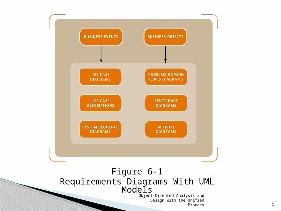
Figure 6-1Requirements Diagrams With UML Models
Object-Oriented Analysis and Design with the Unified Process
6
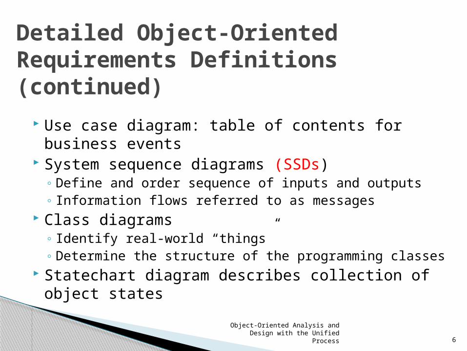
Use case diagram: table of contents for business events
System sequence diagrams (SSDs)◦ Define and order sequence of inputs and outputs ◦ Information flows referred to as messages
Class diagrams ◦ Identify real-world “things” ◦ Determine the structure of the programming classes
Statechart diagram describes collection of object states
Detailed Object-Oriented Requirements Definitions (continued)

Object-Oriented Analysis and Design with the Unified Process
7
Define use cases into two tiers:◦ Overview level derived from:
Event table and use case diagrams
◦ Detailed level derived from combination of: Use case description
Activity diagram
Sequence diagram
System Processes—A Use Case/Scenario View
Object-Oriented Analysis and Design with the Unified Process
8
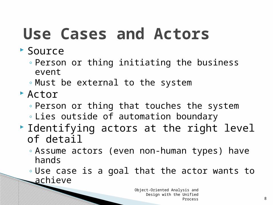
Source◦ Person or thing initiating the business event◦ Must be external to the system
Actor◦ Person or thing that touches the system ◦ Lies outside of automation boundary
Identifying actors at the right level of detail◦ Assume actors (even non-human types) have
hands◦ Use case is a goal that the actor wants to achieve
Use Cases and Actors

Object-Oriented Analysis and Design with the Unified Process
9
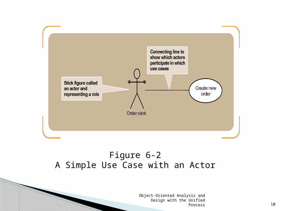
Notation for use case diagrams
◦ Simple stick figure represents an actor
◦ Actor’s hands indicate direct system access
◦ Use case itself symbolized by an oval
◦ Connecting lines match actors to use cases
Actors may also be other system interfaces
◦ May be represented with stick figure or rectangle
The Use Case Diagram
Object-Oriented Analysis and Design with the Unified Process
10
Figure 6-2A Simple Use Case with an Actor
Object-Oriented Analysis and Design with the Unified Process
11
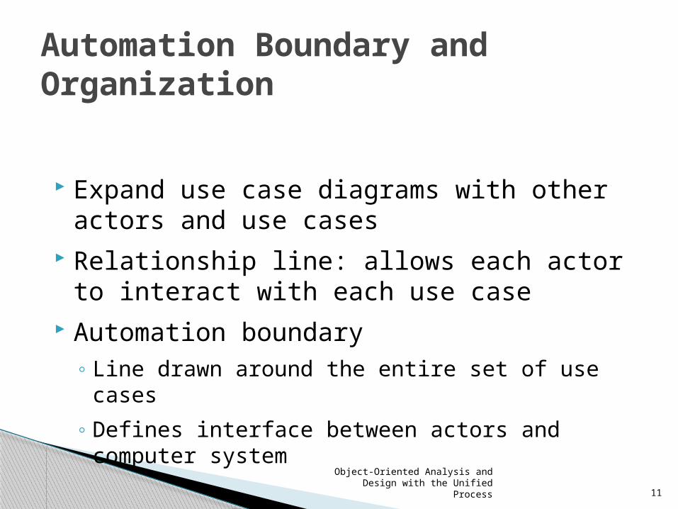
Expand use case diagrams with other actors and use cases
Relationship line: allows each actor to interact with each use case
Automation boundary◦ Line drawn around the entire set of use cases
◦ Defines interface between actors and computer system
Automation Boundary and Organization

Object-Oriented Analysis and Design with the Unified Process
12
Figure 6-3A Use Case Diagram of the Order-Entry Subsystem for RMO,
Showing a System Boundary
Object-Oriented Analysis and Design with the Unified Process
13
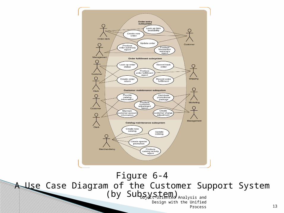
Figure 6-4A Use Case Diagram of the Customer Support System (by Subsystem)
Object-Oriented Analysis and Design with the Unified Process
14
«includes» or «uses» relationship◦ Use case calling services of common subroutine
◦ Common subroutine itself becomes additional use case
Examples: “Validate customer account” and “Look Up Item Availability”
Notation ◦ Relationship denoted by connecting line with arrow
◦ Direction of the arrow indicates major/minor cases
« Includes » Relationships

Object-Oriented Analysis and Design with the Unified Process
15
Figure 6-6An Example of the Order-entry Subsystem With «Includes» Use Cases
Object-Oriented Analysis and Design with the Unified Process
16
Two ways to identify additional use cases ◦ Divide one large use case into two ◦ Define another use case based on a common subroutine
Distinguish between temporal and state events Iterative process translates business events to
use cases ◦ [1] Identify the actors and roles for each use case ◦ [2] Extract system response to business events
Data of system stabilizes after completion of the goal
Developing a Use Case Diagram
Object-Oriented Analysis and Design with the Unified Process
17
Use cases have internal complexity
◦ Sequence of steps to execute business process
◦ Several variations may exist within single use case
Valid variation known as scenario
◦ Example: “Create new order” varies from phone to Internet order
Work with variety of diagrams and descriptions for each use case
Use Case Detailed Descriptions

Object-Oriented Analysis and Design with the Unified Process
18
Use case descriptions written at (3) levels of detail◦ Brief description
Summary statement conjoined to activity diagram
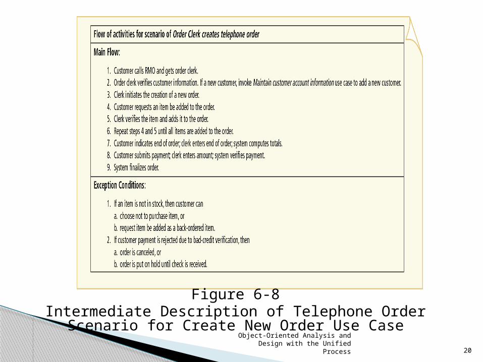
◦ Intermediate description Expands brief description with internal flow of activities
◦ Fully Developed Description Expands intermediate description for richer view
Use Case Detailed Descriptions (continued)

Object-Oriented Analysis and Design with the Unified Process
19
Figure 6-7Brief Description of Create New Order Use Case
Object-Oriented Analysis and Design with the Unified Process
20
Figure 6-8Intermediate Description of Telephone Order Scenario for Create
New Order Use Case

Object-Oriented Analysis and Design with the Unified Process
21
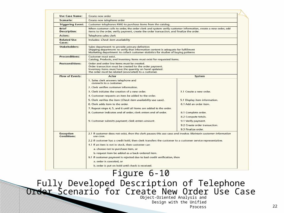
Fully developed use case description◦ Superset of intermediate and brief descriptions◦ Consists of eleven compartments ◦ User, actor, stakeholder, EBP, and conditions
identified Activity Diagram Description
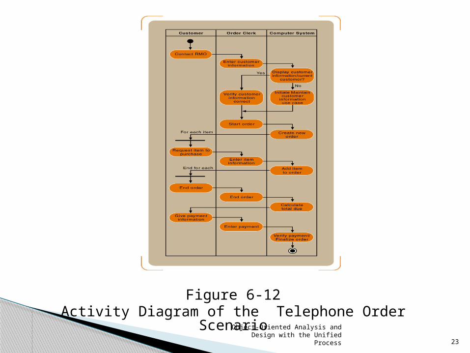
◦ Document the workflows of business processes◦ Document flow of activities for use case
scenarios◦ Form basis of system sequence diagrams (SSDs)
Use Case Detailed Descriptions (continued)
Object-Oriented Analysis and Design with the Unified Process
22
Figure 6-10Fully Developed Description of Telephone Order Scenario for
Create New Order Use Case
Object-Oriented Analysis and Design with the Unified Process
23
Figure 6-12Activity Diagram of the Telephone Order Scenario

Object-Oriented Analysis and Design with the Unified Process
24
System sequence diagram (SSD)
◦ Describes flow of information
◦ Identifies interaction between actors and system
◦ Message oriented
Identifying Inputs and Outputs—the System Sequence Diagram

Object-Oriented Analysis and Design with the Unified Process
25
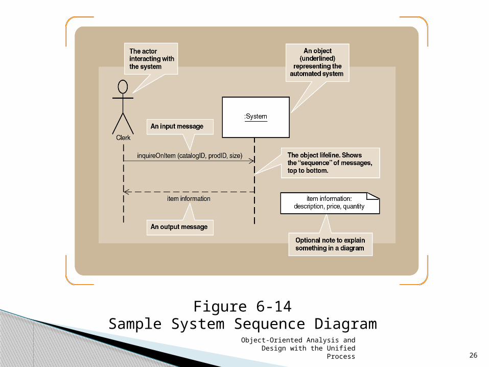
Actor “interacts” with the system via input/output
SSDs use object notation◦ Box (rectangle) refers to individual object◦ Name of the object underlined◦ Messages sent/received by objects, not classes
Lifeline◦ Extension of object or actor for duration of the SSD◦ Indicates sequence of the messages sent/received
SSD Notation
Object-Oriented Analysis and Design with the Unified Process
26
Figure 6-14Sample System Sequence Diagram

Object-Oriented Analysis and Design with the Unified Process
27
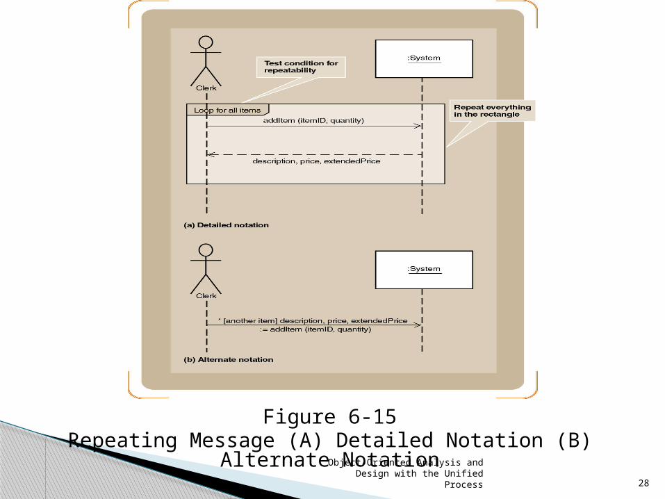
Message syntax can take several forms
◦ Depends on send/return direction
Message semantics: actions (like commands) invoked on destination object
Complete message notation:*[true/false condition] return-value := message-name (parameter-list)
SSD Notation (continued)
Object-Oriented Analysis and Design with the Unified Process
28
Figure 6-15Repeating Message (A) Detailed Notation (B) Alternate Notation
Object-Oriented Analysis and Design with the Unified Process
29
Begin with detailed description of use case◦ Fully developed form◦ Activity diagrams
(4) step process for turning activity diagram into SSD ◦ [1] Identify the input messages ◦ [2] Describe messages from external actor to system ◦ [3] Identify/apply special conditions to input messages◦ [4] Identify and add the output return messages
Developing a System Sequence Diagram

Object-Oriented Analysis and Design with the Unified Process
30
Figure 6-16A Simplified Diagram of the Telephone Order Scenario

Object-Oriented Analysis and Design with the Unified Process
31
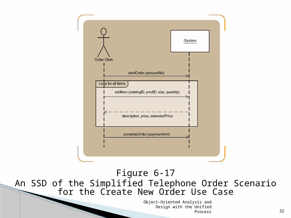
Names of messages reflect services performed
Important principle for identifying data parameters ◦ Base the list on the class diagram
◦ Attributes from the classes listed as parameters
Iteratively define input/output parameters around workflows
Objective: discovery and understanding
Developing a System Sequence Diagram (continued)
Object-Oriented Analysis and Design with the Unified Process
32
Figure 6-17An SSD of the Simplified Telephone Order Scenario for the Create New
Order Use Case

Object-Oriented Analysis and Design with the Unified Process
33
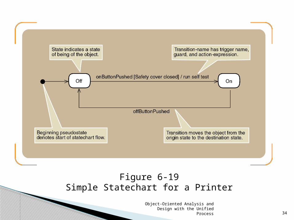
A state in a statechart similar to status condition ◦ Spans many business events
◦ Developed for complex problem domain classes
Statechart diagram ◦ Composed of ovals representing status of object
◦ Arrows represent transitions
Identifying the Object Behaviorthe Statechart Diagram
Object-Oriented Analysis and Design with the Unified Process
34
Figure 6-19Simple Statechart for a Printer

Object-Oriented Analysis and Design with the Unified Process
35
Guidelines to help identify states◦ Check naming convention for status conditions ◦ Simple states reflect simple conditions such as
“On” ◦ Complex states labeled with gerunds or verb
phrases Example: “Being shipped”
◦ Active states usually not labeled with nouns ◦ Describe only states of being of the object itself◦ Status conditions reported to
management/customers Example: “Shipped”
Identifying the Object Behaviorthe Statechart Diagram (continued)
Object-Oriented Analysis and Design with the Unified Process
36
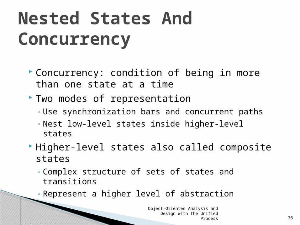
Concurrency: condition of being in more than one state at a time
Two modes of representation◦ Use synchronization bars and concurrent paths◦ Nest low-level states inside higher-level states
Higher-level states also called composite states◦ Complex structure of sets of states and
transitions ◦ Represent a higher level of abstraction
Nested States And Concurrency
Object-Oriented Analysis and Design with the Unified Process
37
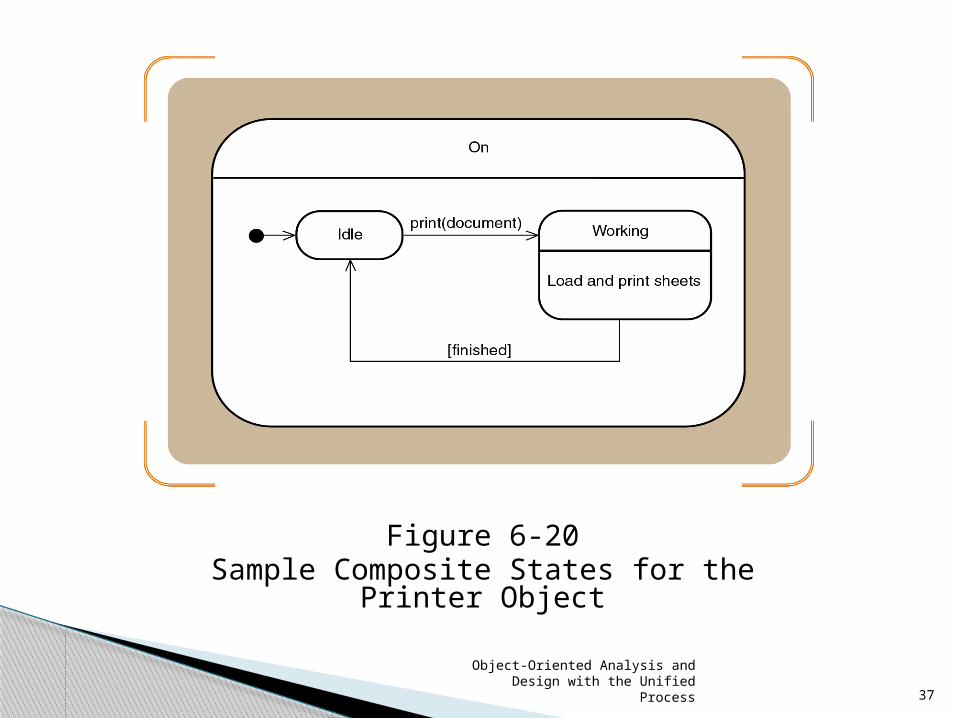
Figure 6-20Sample Composite States for the Printer Object

Object-Oriented Analysis and Design with the Unified Process
38
Figure 6-21Concurrent Paths for the Printer in the On State
Object-Oriented Analysis and Design with the Unified Process
39
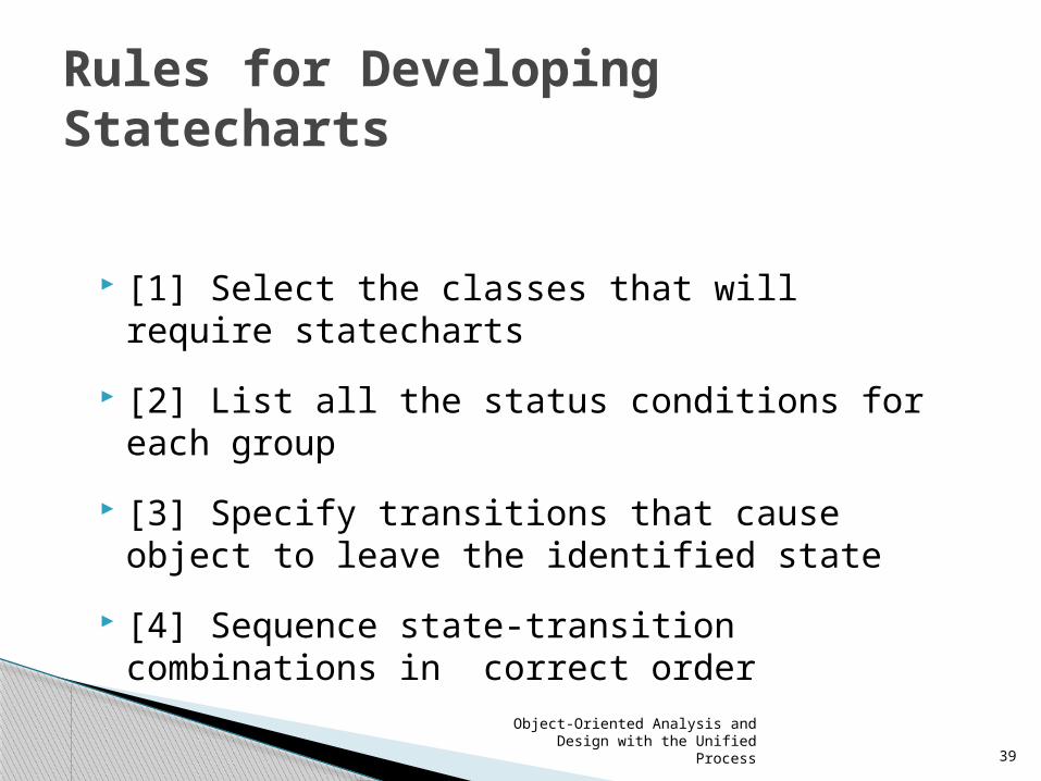
[1] Select the classes that will require statecharts
[2] List all the status conditions for each group
[3] Specify transitions that cause object to leave the identified state
[4] Sequence state-transition combinations in correct order
Rules for Developing Statecharts

Object-Oriented Analysis and Design with the Unified Process
40
[5] Identify concurrent paths.
[6] Look for additional transitions
[7] Expand each transition as appropriate
[8] Review and test each statechart
Rules for Developing Statecharts (continued)

Object-Oriented Analysis and Design with the Unified Process
41
Review the domain class diagram Select classes with status conditions that
need to be tracked Candidates: Order, OrderItem,
InventoryItem, Shipment, Customer Choose Order and OrderItem
◦ Simplicity ◦ Location in the class hierarchy
Developing RMO Statecharts
Object-Oriented Analysis and Design with the Unified Process
42
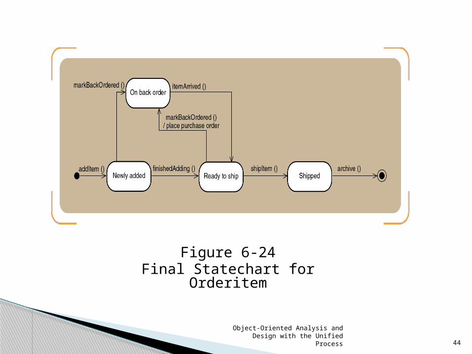
Identify possible status conditions of interest
◦ “Ready to be shipped”
◦ “On back order”
◦ “Shipped”
Continue developing statechart according to eight rules
Developing The Order Item State Chart

Object-Oriented Analysis and Design with the Unified Process
43
Figure 6-22States and Exit Transitions for Orderitem
Object-Oriented Analysis and Design with the Unified Process
44
Figure 6-24Final Statechart for Orderitem

Object-Oriented Analysis and Design with the Unified Process
45
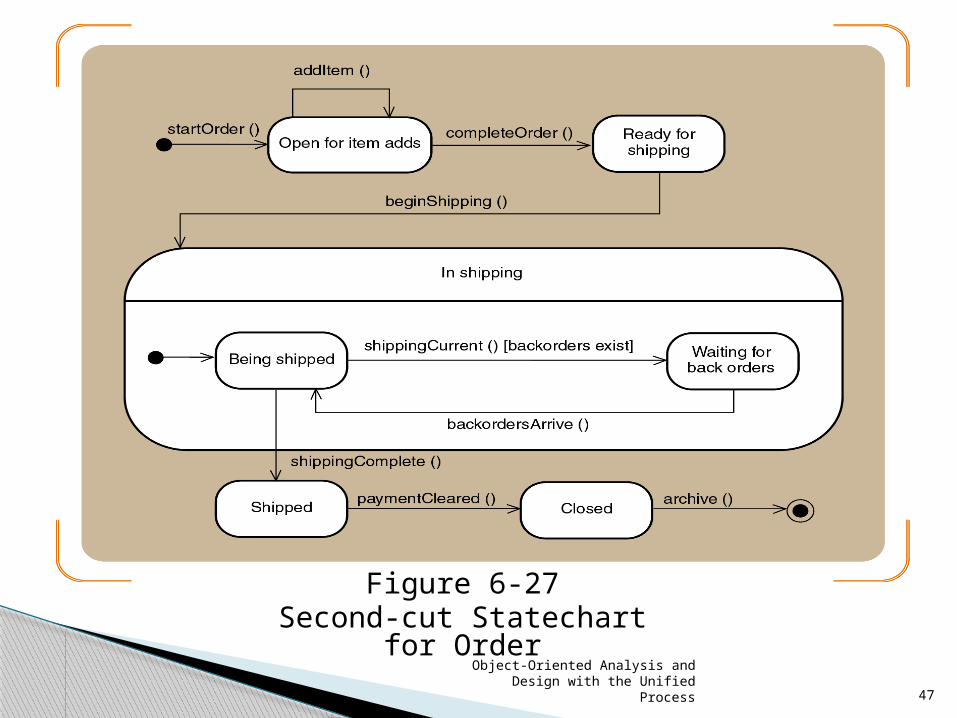
States mirror the life cycle of an order Application of rules leads to greater
complexity◦ Concurrent states◦ New transitions
Benefits of developing a statechart for an object◦ Captures and clarifies business rules◦ Gain true understanding of system requirements
Developing the Order State Chart
Object-Oriented Analysis and Design with the Unified Process
46
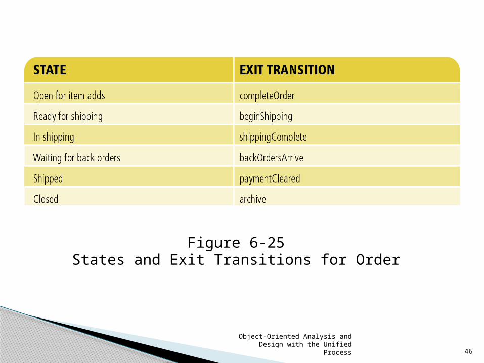
Figure 6-25States and Exit Transitions for Order
Object-Oriented Analysis and Design with the Unified Process
47
Figure 6-27Second-cut Statechart for Order
Object-Oriented Analysis and Design with the Unified Process
48
Primary (or source) models◦ Use case diagram ◦ Problem domain class diagram
CRUD analysis validates model completeness
Construction of one model depends on another
Models capturing processes of new system◦ Use case diagram and models to lower left
Models capturing information about classes◦ Class diagrams and dependencies
Integrating Object-Oriented Models

Object-Oriented Analysis and Design with the Unified Process
49
Figure 6-28Relationships among OO Requirements Models

Object-Oriented Analysis and Design with the Unified Process
50
Summary
OOA family of models documents users’ needs and defines system requirements
Use case detailed models (descriptive or activity)
Sequence diagrams (SSDs)
Domain model class diagrams
Statechart diagrams
Object-Oriented Analysis and Design with the Unified Process
51
Use case: single system function responding to an event
Actors: human users or system interfaces that initiate system response
System function decomposed into workflows
SSDs, domain models, statecharts emulate routines and object interaction
Software engineering terms signal transition into design phase
Summary (continued)