* contents · 2 nosen advantages: professional technicians competitive price professiona high...
TRANSCRIPT

0

1
Wo r m Ge a r Sc rew J a c k R N- S e re i s
* Contents
Company……………………………………………………………………………….2
RN-Series Introduction………………………………………………………………...3
RN-Series Technical Datas Sheet……………………………………………………...4
RN-Series Screw Top Ends Types Dimensions……. …………………………………5
RN-Series RN-05T~RN-100T Dimensions…………………………………………....6
RN-Series RN-05T~RN-100T Traveling Nut Dimensions………………………….....7
RN-Series Selection Guide……………………………………………………………..8~13
RN-Series Screw Jack Systems………………………………………………………...14
Screw Jacks Application Pictures……………………………………………………....15~18
RN-Series Installation & Maintenance……. …………………………………..............19~20
RN-Series FAQ…….. ……………………………………………..…………………....21~24
NOSEN Contacts………………………………………..…………………................…25

2
Wo r m Ge a r Sc rew J a c k R N- S e re i s
*Company
COMPANY HISTORY:
In 2003,established Yuanxin Mechanical&Electrical Accessory Shop,Located In Houjie town,Dongguan
city,Guangdong Porvince.
In 2005,named NOSEN Mechanical&Electrical Factory,located in Chang'an town,Dongguan
city,Guangdong province.
In 2006,established Shanghai NOSEN Mechanical&Electrical Equipment Co.,Ltd.
In 2007,named Dongguan Mechanical&Electrical Equipment Co.,Ltd.
In 2007,founded International Sales Department.
In 2008,established NOSEN International Industry(HK) Limited.
In 2008,Dongguan Mechanical&Electrical Equipment Co.,Ltd moves to Houjie town,Dongguan city.
In 2009,NOSEN passed SGS international Certification.
In 2010,NOSEN passed ISO9001:2008 quality managerment systems certifications.Certificate
No.104679.
In 2011,NOSEN named NOSEN M&E TECHNOLOGY CO.,LTD
PRODUCTS HISTORY:
In 2003 R&D,Production and Sale 12 models Worm Gear Screw Jack RN-Series Trapezoidal Screw
Jacks and Sale Taiwan,Japan Power Transmission Products.
In 2005, R&D,Production and Sale 7 models Worm Gear Screw Jack RNK-Series Ball Screw Jacks and
10 models Spiral Bevel Gearboxes.
In 2006, R&D,Production and Sale 8 models RNE Series Stainless Steel Vertical Agitator.
In 2009,R&D,Production and Sale Worm Gear Screw Jack RNS-Series,Patent Right No.
201020105770.X.
In 2010,R&D,Production and Sale Worm Gear Screw Jack RNF-Series. Patent Right No.
20102546844.3.
In 2011,R&D,Production and Sale Spiral Bevel Gearbox RNV-Series.
NOSEN ADVANTAGES:
Professional technicians teams
Competitive Price
Professiona
High Quality
The shorted lead time
Small order acceptable
The best before-sale, while-sale and after-sale service
1 years quality warrenty
SALES REGIONS:
European: BE, BG, DK, EG, FI, DE, GR, NL, PL, ES, SE, UK
America: USA, CA
Asia: IN, ID, MY, PH, QA, RU, SG, TH, VN
Oceania: AU, NZ
Africa: EG
REPRESENTATIVES COUNTRIES: DE, PL

3
Wo r m Ge a r Sc rew J a c k R N- S e re i s
*Introduction
Worm Gear Screw Jack RN-Series, Trapezoidal Screw Jacks.
Models
RN-0.5T,1T,2T,3T,5T,10T,15T,20T,30T,40T,50T,100T
Components
worm gear, worm shaft, bearings, oil sealing, case iron gearbox, shaft cover, top cover, self-locking
trapezoidal screw etc.
Speed of Travel
* Fast Speed
1 turn 1 mm travel
1500 mm/min
* Mid Speed
1 turn 0.5 mm travel
750 mm/min
* Low Speed L
1 turn 0.25 mm travel
375 mm/min
Lateral Force
Usually, screw jack only loads lift screw axial loading, don’t permit to load any lateral force. Any lateral
force will reduce screw jack working life, even damage screw jack. We suggest, lateral forces that may occur
should be taken by an external guide rail.
Self-locking Function
RN-Series trapezoidal type screw is of self-locking. The self-locking function depends on a variety of
parameters: large pitches, different gear ratios, lubrication, friction parameters, Ambient influences( such as
high or low temperatures) , vibrations and mounting position.
Anti-rotation Devices
Single screw jack application, isn’t guided and without any guide rails, lifting screw does not do linear
motions, only rotation, especially light loading. If that is the case, need to extra add anti-rotation devices.
NOSEN keyed screw jack solves this problem.
Stop Collar
Prevents the screw from being removed from the jack gearbox. Following clients requirement, we fit stop
collar for screw jacks. The stop collar cannot be used as a fixed stop.
Accessory:
spiral bevel gearbox, hand wheel, electric motor, proteticve tube, rubber bellows, limited switches, coupling,
flex link shaft, swivel mounting bases, pillow block bearing, counters etc.
Application Industries:
Precision lift table, Roll forming machines, Press machines,Tunnel Freezer, Surface-Gringing machines,
Satellite dish antenna, Solar tracking system, Sluice gate, Theatre stage, Slitting line, Precision leveler,
Powered straightener, Paper machines, Food processing machines, Textiles machines etc.

4
Wo r m Ge a r Sc rew J a c k R N- S e re i s
*Technical Datas Sheet

5
Model A B C CA CD CE CF D E F G H I J K L M N S
RN-05T 135 35 155 130 25 30 100 55 130 25 15 16 8 20 8 55 70 10 M12*1.5
RN-1T 140 35 160 135 25 30 105 55 130 25 15 16 8 24 8 55 70 10 M16*1.5
RN-2T 165 55 165 150 28 40 110 55 135 25 20 16 12 25 10 70 88 10 M20*1.5
RN-3T 195 65 195 180 32 50 130 65 160 30 25 20 14 32 10 80 98 13 M22*2
RN-5T 195 65 195 180 35 50 130 65 160 30 25 25 16 38 12 90 114 13 M28*2
RN-10T 255 65 225 220 40 60 160 65 200 40 32 32 20 45 14 100 138 16 M32*2
RN-15T 255 95 225 220 45 60 160 65 210 50 32 36 24 50 18 110 148 20 M36*2
RN-20T 294 114 250 260 55 80 180 70 235 55 35 44 26 64 21 125 178 25 M42*2
RN-30T 355 135 295 300 65 80 220 75 285 65 44 56 35 75 21 140 188 28 M56*2
RN-40T 410 150 355 360 70 100 260 95 330 70 54 60 38 80 25 170 218 30 M64*2
RN-50T 480 165 429 435 75 120 315 114 390 75 64 70 45 90 27 200 248 32 M76*2
RN-100T 545 200 485 495 100 150 345 140 445 100 70 80 55 100 27 280 358 35 M80*2
Wo r m Ge a r Sc rew J a c k R N- S e re i s
*Screw Top Ends Types Dimensions

6
No. RN-05T RN-1T RN-2T RN-3T RN-5T RN-10T RN-15T RN-20T RN-30T RN-40T RN-50T 100T
AA 150 150 170 220 220 256 264 316 390 420 480 550
AB 75 75 85 110 110 128 132 158 195 210 240 275
AC 45 45 55 70 70 88 92 108 130 145 170 180
AD 30 30 30 40 40 40 40 50 65 65 70 95
AE 25 25 25 35 35 35 35 45 60 60 65 90
AF 60 66 66 80 90 100 110 140 190 210 240 250
AG 82 84 90 110 120 140 150 180 230 260 300 320
AH 56 60 55 70 80 100 100 120 150 165 194 218
AI 131 135 140 180 190 228 232 278 345 375 434 493
BA 41.5 43 50 57 60 90 90 95 110 130 160 170
BB 77.5 79 85 98 110 140 140 155 200 225 255 285
BC 30 35 38 42 45 70 70 75 85 105 130 135
BD 66 65 73 83 95 120 120 135 175 200 225 250
BE 31 30 35 40 50 60 60 70 100 120 130 150
CB 38 36 40 50 50 60 60 70 85 100 120 125
CC 13 13 15 18 18 20 20 25 30 30 30 35
CD 62 69 70 80 80 100 100 110 135 135 195 220
CF 100 105 110 130 130 160 160 180 220 260 315 345
H 9 9 12 12 14 18 18 18 22 22 22 27
U 13 15 15 18 18 25 25 28 32 35 45 50
T*V 3*2 5*2.5 5*3 6*3.5 6*3.5 8*4 8*4 8*4 10*5 10*5 14*5.5 14*5.5
T*V (3*2) (5*2.5) (5*3) (5*3) (5*3) (7*4) (7*4) (7*4) (10*5) (10*5) (14*5.5) (14*5.5)
LA 104 104 130 130 130 165 165 165 215 215 265 265
LB 83 83 110 110 110 130 130 130 180 180 230 230
LZ M6-P1*4 M8-P1.25*4 M10-P1.5*4 M12-P1.75*4 M16-P2*4
WY
HP
3*1.5
60/90W
3*1.5
60/90W
4*2
1/4HP
5*2.3
1/2HP
5*2.3
1/2HP
6*2.8
1HP
6*2.8
1HP
8*3.3
2HP
8*3.3
3HP
8*3.3
5HP
10*3.3
7.5HP
10*3.3
10HP
WY
HP
3*1.5
60/90W
3*1.5
60/90W
4*2
1/4HP
5*2.3
1/2HP
5*2.3
1/2HP
8*3.3
2HP
8*3.3
2HP
8*3.3
2HP
8*3.3
3HP
8*3.3
5HP
10*3.3
7.5HP
10*3.3
10HP
d 10 10 11 14 14 19 19 24 28 28 38 38
Wo r m Ge a r Sc rew J a c k R N- S e re i s
* RN-05T~RN-100T Dimensions

7
Wo r m Ge a r Sc rew J a c k R N- S e re i s
*Traveling Nut Dimensions

8
Wo r m Ge a r Sc rew J a c k R N- S e re i s
*Selection Guide
Full Models Explanation
Model: RN-3T
Installation: A
Screw top ends type: R
Input forms: MDR
Gear ratio: 1/12
Travel stroke: 300 mm
Accessory: P (steel tube)
9
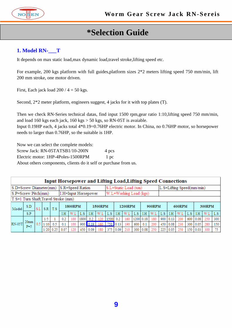
1. Model RN-___T
It depends on max static load,max dynamic load,travel stroke,lifting speed etc.
For example, 200 kgs platform with full guides,platform sizes 2*2 meters lifting speed 750 mm/min, lift
200 mm stroke, one motor driven.
First, Each jack load 200 / 4 = 50 kgs.
Second, 2*2 meter platform, engineers suggest, 4 jacks for it with top plates (T).
Then we check RN-Series technical datas, find input 1500 rpm,gear ratio 1:10,lifting speed 750 mm/min,
and load 160 kgs each jack, 160 kgs > 50 kgs, so RN-05T is avaiable.
Input 0.19HP each, 4 jacks total 4*0.19=0.76HP electric motor. In China, no 0.76HP motor, so horsepower
needs to larger than 0.76HP, so the suitable is 1HP.
Now we can select the complete models:
Screw Jack: RN-05TATSB1/10-200N 4 pcs
Electric motor: 1HP-4Poles-1500RPM 1 pc
About others components, clients do it self or purchase from us.
Wo r m Ge a r Sc rew J a c k R N- S e re i s
*Selection Guide

10
Wo r m Ge a r Sc rew J a c k R N- S e re i s
*Selection Guide
2. Installations
Translating screw jack: A & B
Keyed screw jack: C & D
Rotating screw jack: E & F
11
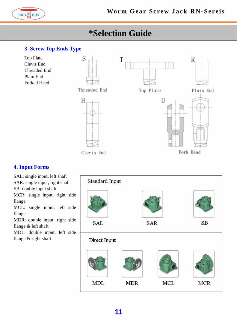
3. Screw Top Ends Type
Top Plate
Clevis End
Threaded End
Plain End
Forked Head
4. Input Forms
SAL: single input, left shaft
SAR: single input, right shaft
SB: double input shaft
MCR: single input, right side
flange
MCL: single input, left side
flange
MDR: double input, right side
flange & left shaft
MDL: double input, left side
flange & right shaft
Wo r m Ge a r Sc rew J a c k R N- S e re i s
*Selection Guide

12
6. Travel Stroke, mm
5. Gear Ratio
Manual Operated
Fast speed : 1 full turn 1 mm travel
Mid speed : 1 full turn 0.5 mm travel
Low speed : 1 full turn 0.25 mm travel
Electric Driven
Fast speed : 1500 mm/min
Mid speed : 750 mm/min
Low speed : 375 mm/min
Wo r m Ge a r Sc rew J a c k R N- S e re i s
*Selection Guide

13
7. Accessories
Wo r m Ge a r Sc rew J a c k R N- S e re i s
*Selection Guide

14
Wo r m Ge a r Sc rew J a c k R N- S e r i e s
* Screw Jack Systems

15
Wo r m Ge a r Sc rew J a c k R N- S e r i e s
* Application Pictures

16
Wo r m Ge a r Sc rew J a c k R N- S e r i e s
* Application Pictures

17
Wo r m Ge a r Sc rew J a c k R N- S e r i e s
* Application Pictures

18
Wo r m Ge a r Sc rew J a c k R N- S e r i e s
* Application Pictures

19
Wo r m Ge a r Sc rew J a c k R N- S e r i e s
* Installation
Direction of rotation: Before starting installation work, the direction of rotation of all worm gear screw
jacks, spiral bevel gear boxes and the drive motor must be checked with regard to the feed direction of each
individual worm gear screw jack.
Alignment errors: All components must be carefully aligned during installation. Alignment errors and
stresses increase power consumption and lead to overheating and premature wear. Before a drive unit is
attached, each worm gear screw jack should be turned through its entire length by hand without load.
Variations in the amount of force required and/or axial marks on the outside diameter of the screw indicate
alignment errors between the worm gear screw jack and its additional guides. In this case, the relevant
mounting bolts must be loosened and the worm gear screw jack turned through by hand again. If the amount
of force required is now constant throughout, the appropriate components must be aligned. If not, the
alignment error must be localized by loosening additional mounting bolts.
Test run: The direction of rotation of the complete system and correct operation of the limit switches must
be checked again before attaching the drive motor. In the case of translating screw jack, check that the screw
is lubricated with grease from the interior of the gear box and relubricate if necessary. In the case of rotating
screw jack, the jack screw should be coated with suitable grease to provide lubrication for lifting operation.
The first test runs can then be carried out without load. A maximum operating time of 30% can not be
exceeded at trial runs under londing for worm gear screw jacks with trapezoidal screws.
Operation: The loads, speeds and operating conditions specified for the worm gear screw jacks and
transmission components must not be exceeded even briefly. Failure to observe this condition will invalidate
all claims under guarantee.
Notes:
1. The jack must not be overloaded.
2. Max rpm should not exceed 1800.
3. Jacks are designed primarily to raise and lower loads and any side thrust should be avoided.These units
will withstand some side thrust,depending on diameter of the screw and the extended length of the
screw.Where side thrusts are present,the loads should be guided and the guides,meanwhile consult our
enginers.
4. The base,on which the jacks are mounted,should be strong enough to carry the max. load and should be
rigid enough to prevent swings or turns on the supporting beam of the jack.
20
Wo r m Ge a r Sc rew J a c k R N- S e r i e s
* Maintenance
Safety: All mounting bolts must be retightened after a short period of operation. Under extreme operating
conditions, the wear on the screw nut (worm gear) must be checked at shorter intervals, depending on the
power-on time, by inspecting the play in the thread. The screw nut (worm gear) must be replaced if the axial
backlash with a singlestart thread is more than one-quarter of the thread pitch.
Lubrication: The worm gear screw jacks are lubricated by the manufacturer and are ready for operation on
delivery. Screw jacks must be lubricated via their grease nipples with one of the greases specified below at
intervals of 300 operating hours. The screw should be cleaned and greased at the same time. We recommend
that the gear box be cleaned to remove old grease and refilled with fresh grease after approx. 700 operating
hours or 18 months. The worm gear screw jacks can be dismantled relatively easily:
■ Unscrew the two threaded pins securing the bearing cover.
■ Unscrew the screw and remove the screw protection if necessary.
■ Unscrew the bearing cover with the aid of a face spanner.
Please proceed as follows to refit the bearing cover:
Mount the bearing cover with face spanner and check the operation performance of the worm wheel gear set.
Too big force influences the easy movement for smaller screw jack sizes. When necessary the securing holes
at the bearing cover have to be drilled again.
Standard grease: NLGI grade #2

21
Wo r m Ge a r Sc rew J a c k R N- S e r i e s
* FAQ
Q: What is the difference between a trapezoidal screw jack and a ball screw jack?
A: The trapezoidal screw jack uses an acme threaded screw that is typically self-locking, meaning it will
hold its position without a brake. Ball screw jacks use ball screws to convert rotary motion to linear
movement, and require 1/3 the horsepower compared to a trapezoidal screw jacks. Due to the efficiency of
the ball screw,brakes must be used to stop and hold the load screw in position. Brakes are also recommended
for use on any jacks if vibration is present.
Trapezoidal screw jack is of low efficiency,low speed,heavy duty,infrequently use
Ball screw jack is of high efficiency,high speed,low loading,frequently use,high accuracy,long life
Q: What is translating screw jack?
A: A driven worm shaft acts on an internal worm gear, which in turn drives a lifting screw to extend or
retract. As the lifting screw translates through cast iron housing,then worm gear and lifting screw rotate
together.When the lifting screw is held to prevent rotation,the lifting screw will move linearly through the
cast iron housing to move the load.
Q: What is keyed screw jack?
A: Some loads don’t prevent lifting screw rotation. These applications require a keyed screw jack. A key,
fixed to the jack housing and inserted into a keyway milled into the lifting screw, forces the lifting screw to
translate without rotating.
Q: What is rotating screw jack?
A: A lifting screw keyed to the worm gear as a single unit, forcing the lifting screw to rotate,but not translate.
A travelling nut, attached to the load, is driven by the rotation of the lifting screw. This type jack is ideal for
applications that can not accommodate a screw protection tube and save enough mounting space.
Q: What is anti-backlash screw jack?
A: Anti-backlash screw jack is used wherever reversible load coditions require precision positioning control.
Adjustable backlash screw jack models are available to reduce backlash. But should not be used to
completely eliminate backlash. While it may be desirable to totally eliminate backlash, the result would be a
lock-up of lifting screw and drive sleeve.
Q: What kind of machine needs to use anti-backlash screw jack?
A: At present, it is used to precision leveler and roll forming auto pro mill machine etc.
For reduced axial lifting screw backlash,need to select the model with anti-backlash devices. This is typically
used when the load direction changes from tension to compression and mini axial lifting screw backlash is
required. This design in only available for translation screw jacks. It can be combined with anti-rotation
devices as well.

22
Wo r m Ge a r Sc rew J a c k R N- S e r i e s
* FAQ
Q: Can the lifting screw be keyed to prevent rotation?
A: Yes, Keyed screw jack. We also recommend the following methods for preventing rotation. For single screw
jack applications, no any guides,it needs to use keyed screw jack.
Below applications conditions, don’t need keyed screw jacks.
1.For multiple screw jacks arrangement.
2.Single screw jack with full guides.
Q: Should the load being positioned be guided?
A: It is highly recommended that the load be guided, however,it is not necessary. A guided system will provide
more column stability and allow longer lifting screw travel. Column length is greatly reduced on unguided
systems. External load forces common with unguided systems are detrimental to the life and operation.
Q: Is the screw jack self-locking?
A: NOSEN RN-Series & RNF-Series screw jacks are self-locking in most case. All ball screw jacks are not
self-locking,it will require a brake or other control device. If vibration conditions exist, please consult our
engineers.
Q: Can the screw jack be operated in multiple units?
A: Perhaps the greatest single advantage of screw jacks is that they can be tied together mechanically, to lift and
lower in unison. Typical arrangements involving screw jacks,bevel gearboxes,motors,reducers,flex shaft and
coupling etc.
Q: What is the efficiency of multiple screw jacks arrangement?
A: In addition to the efficiencies of screw jacks and bevel gearboxes, the efficiency of the multiple screw jacks
arrangement must be taken into consideration. The arrangement efficiency allows for misalignment due to slight
deformation of the structure under load, for the losses in couplings and bearings,and for a normal amount of
misalignment in positioning the jacks and bevel gearboxes.We use the following efficiencies (all standard units):
Two Jacks Arrangement - 95%
Three Jacks Arrangement - 90%
Four Jacks Arrangement - 85%
Six or Eight Jacks Arrangement - 80%
Q: Can the screw jack be operated at high speeds?
A: The input KW to these screw jacks should not exceed the KW rating shown in the technical datas sheet.
Maximum RPM should not exceed 1800. We cannot accept responsibility for the overheating and rapid wear that
may occur should these limits be exceeded Kilowatts increases in direct proportion to the speed.
Q: Will the screw jack withstand a side thrust?
A: Screw jacks are designed primarily to raise and lower axial loads and any side thrust should be avoided. These
jacks will withstand some side thrust, depending on diameter of the screw and the extended length of the screw.
Where side thrusts are present, the loads should be guided and the guides, rather than the jack units, should take
the side thrust – particularly when long raises are involved. Even a small side thrust can exert great force on the
housings and bearings and increase the operating torque.

23
Wo r m Ge a r S c rew J a c k R N- S e r i e s
* FAQ
Q: Will the screw jack withstand a side thrust?
A: Screw jacks are designed primarily to raise and lower axial loads and any side thrust should be avoided.
These jacks will withstand some side thrust, depending on diameter of the screw and the extended length of the
screw. Where side thrusts are present, the loads should be guided and the guides, rather than the jack units,
should take the side thrust – particularly when long raises are involved. Even a small side thrust can exert great
force on the housings and bearings and increase the operating torque.
Q: How is the lifting screw protected?
A: For translating screw jacks are fitted with a screw protective tube that stores the screw when the jack is in the
closed position. Rubber bellows are available and recommended to protect the screw in the extended position.
Two rubber bellows may be required for rotating screw jacks with travelling nuts.
Q: What do i need to consider when order a rubber bellows to protect the jack lifting screw?
A: When a rubber bellows is ordered for a jack, the closed height dimensions may change. When ordering a
rubber bellows for an inverted jack, need to consider the closed height of the rubber bellows and structure
thickness. Usually, under fully retracted, the rubber bellows closed height = 0.13 * traveling strokes.
For example, upright mounting, request 1000 mm stroke, plus rubber bellows closed height 0.13*1000=130 mm.
So need to order 1130 mm stroke with rubber bellows.
Q: Can the screw jack be used where vibration is present?
A: Yes, but vibration can cause the lifting screw to creep or inch down under load. For applications involving
slight vibration,select the higher of the worm gear ratios.Should considerable vibration be present, use a drive
motor equipped with a magnetic brake which will prevent the screw jack model from self-lowering.
Q: Will the screw jack drift after motor switched off?
A: Yes, unless a brake of sufficient capacity is used to prevent it. The amount of drift will depend upon the load
on the screw jack and the inertia of the rotor in the motor.
Q: If screw jack suitable for high/low temperature opetation?
A: Using standard greases and oil seals,the screw jack is normally suitable for operation at ambient temperatures
range: -20℃ to +80℃. At present, we have clients use screw jacks at +300℃ high temperatures with special
grease and seals in Glass Industry. Any special working temperature, please contact NOSEN sales or engineers.
Q: How to calculate lifting speed with a given worm shaft speed?
A: When the worm shaft speed is known, the distance the load can be raised per minute can be determined with
this formula:
Lifting speed = rpm of worm shaft * lifting screw pitch / worm gear ratios
Lifting speed = travel per worm shaft turn (mm) x rpm of worm shaft
For example:
RN-5T, Pitch=6mm, worm gear ratio 1:24, with 1500 rpm,4 poles electric motor, lifting speed=1500 rpm * 6
mm / 24(ratio) = 375 mm/min, or lifting speed=stroke 0.25mm per turn *1500 rpm=375 mm/min.

24
Wo r m Ge a r Sc rew J a c k R N- S e r i e s
* FAQ
Q: What is the difference between upright and inverted jack configurations?
A: The difference between an upright and inverted jack is the location at which the jack screw exits the jack
relative to the jack base. For example, an upright jack’s lifting screw exits the jack opposite the base. An
inverted jack’s lifting screw exits the jack on the same side as the base. The choice between an inverted or
upright jack is totally dependent upon your application. Upright and inverted jacks can be viewed on any of the
jack drawings.
Note: An upright jack mounted upside down is still referred to as an upright jack.
Q: Are NOSEN screw jacks lubricated prior to shipment?
A: All NOSEN screw jacks are lubricated for normal operation before leaving the factory and are ready for use.
The standared lubrication is NLGI grade #2.
Q: After how many hours,i need to lubricate the screw jack units?
A: Normal working conditions,after 300 work hours,first time to inject grease. After that,each time per 1000
work hours.
Q: Can I buy a screw jack with a clevis on both ends?
A: Yes, when freedom of movement in two axes is required, a double clevis jack may be specified. This design
incorporates a clevis machined or pinned on the screw end and a clevis welded to the protection tube. Double
clevis jacks are useful in applications that require actuating a hinged platform or door.
Q: How do I stop screw jack at the travel limits?
A: Limited switches or other controls must be used to shut off the motor when the jack has reached its full
extended or retracted position. Solid stops are not recommended. Their continued use can cause severe damage
to the jack.
Q: What is the life of trapezoidal screw jack?
A: Under normal conditions, 300 mm stroke, it can lift 10000 times. Total travel stroke 3000000 mm. For
example, RN-5T jack with 100 mm stroke, lift 5 time per day, how many years for it?
3000000 mm / (100*5) = 6000 days = 16.5 years.
Q: How much backlash is there in the screw jacks?
A: Trapezoidal screw, Anti-backlash and Ball screw models must be considered separately, as the normal
backlash will vary due to different constructions.
Trapezoidal screw endplay 0.1 mm,radial play 0.1 mm
Anti-backlash screw endplay 0.01 mm, radial play 0.01 mm
Ball screw endplay 0.01 mm, radial play 0.01 mm

25
Wo r m Ge a r Sc rew J a c k R N- S e r i e s
* Contacts
* Factory & Office -- Dongguan city
NOSEN M&E TECHNOLOGY CO.,LTD
Address: Building F,Xinhaoyuan Industrial Park,Xitou Village,Houjie Town,Dongguan City,Guangdong
Province,China
Postcode: 523952
Tel: + 86 769 85644651
Fax: + 86 769 85644652
Mobile: + 86 13532664175
Contact: Jack Kuang (sales manager)
Email: [email protected]
Skype: j.kuang88
MSN: [email protected]
* Office -- Kun Shan city
Address: Room 303,Building 28,Furong Garden District,Lujia Town,Suzhou Kunshan City,Jiangsu Province,China
Tel: + 86 512 55112855
Fax: + 86 512 55112856
Mobile: + 86 18952457825
Contact: Mr Peng(sales manager)
* Office -- Hong Kong
NOSEN INT'L INDUTRY(HK) LIMITED
Address: Flat1801A,18/F.,On Hong Commercial Bldg,145 Hennessy Road,Wanchai,Hongkong.
Tel: +852 39711675
Fax: +852 35430978
* Representative -- Germany
ARNOLD REITZ SYSTEMTECHNIK E.K.
ADD:Friedrich-Hornfeck-Straße 10 63628 Bad Soden-Salmünster
Tel: 06056/740484
Fax:06056/740485
Contact: Arnold Reitz
* Representative -- Poland
PROXY MOTION
ADD: ul. Młodzieżowa 26, 87-100 Toruń, Poland
Tel: 48 56 682 81 43
Fax: 48 56 682 81 41
Contact: Pawel Korzeniowski