yp250 - majestyclub.czmajestyclub.cz/wp-content/uploads/2017/01/manual-yamaha-majesty... · as the...
TRANSCRIPT

OWNER’S MANUAL
5GM-28199-E0
YP250
5GM-9-E0(Hyoushi) 4/13/0 9:16 PM Page 1 (2,1) (Magenta plate)

siro page 4/6/0 3:58 AM Page 1

EAU00001
INTRODUCTION
1
2
4
5
6
7
8
9
Welcome to the Yamaha world of motorcycling!
As the owner of a YP250, you are benefiting from Yamaha’s vast experience in and newest technolo-gy for the design and the manufacture of high-quality products, which have earned Yamaha a reputa-tion for dependability.
Please take the time to read this manual thoroughly, so as to enjoy all your YP250’s advantages. Theowner’s manual does not only instruct you in how to operate, inspect and maintain your scooter, butalso in how to safeguard yourself and others from trouble and injury.
In addition, the many tips given in this manual will help to keep your scooter in the best possible con-dition. If you have any further questions, do not hesitate to contact your Yamaha dealer.
The Yamaha team wishes you many safe and pleasant rides. So, remember to put safety first!
5GM-9-E0 4/13/0 9:05 PM Page 1

EAU00005
IMPORTANT MANUAL INFORMATION
1
2
3
4
5
6
7
8
9
Particularly important information is distinguished in this manual by the following notations:
The Safety Alert Symbol means ATTENTION! BECOME ALERT! YOUR SAFETYIS INVOLVED!
Failure to follow WARNING instructions could result in severe injury or death tothe scooter operator, a bystander or a person inspecting or repairing the scooter.
A CAUTION indicates special precautions that must be taken to avoid damage tothe scooter.
A NOTE provides key information to make procedures easier or clearer.
Q
w
cC
NOTE:
NOTE:8 This manual should be considered a permanent part of this scooter and should remain with it
even if the scooter is subsequently sold.8 Yamaha continually seeks advancements in product design and quality. Therefore, while this
manual contains the most current product information available at the time of printing, theremay be minor discrepancies between your scooter and this manual. If there is any questionconcerning this manual, please consult your Yamaha dealer.
5GM-9-E0 4/13/0 9:05 PM Page 2

IMPORTANT MANUAL INFORMATION
1
2
4
5
6
7
8
9
EW000002
w
PLEASE READ THIS MANUAL CAREFULLY AND COMPLETELY BEFORE OPERATINGTHIS SCOOTER.
5GM-9-E0 4/13/0 9:05 PM Page 3

1
2
3
4
5
6
7
8
9
YP250OWNER’S MANUAL
©1999 by Yamaha Motor Co., Ltd.1st Edition, October 1999
All rights reserved. Any reprinting orunauthorized use without the written
permission of Yamaha Motor Co., Ltd.is expressly prohibited.
Printed in Japan
EAU00008
5GM-9-E0 4/13/0 9:05 PM Page 4

EAU00009
TABLE OF CONTENTS
1 GIVE SAFETY THE RIGHT OF WAY
2 DESCRIPTION
3 INSTRUMENT AND CONTROL FUNCTIONS
4 PRE-OPERATION CHECKS
5 OPERATION AND IMPORTANT RIDING POINTS
6 PERIODIC MAINTENANCE AND MINOR REPAIR
7 SCOOTER CARE AND STORAGE
8 SPECIFICATIONS
9 CONSUMER INFORMATION
INDEX
9
8
7
6
5
4
3
2
1
5GM-9-E0 4/13/0 9:05 PM Page 5

5GM-9-E0 4/13/0 9:05 PM Page 6

GIVE SAFETY THE RIGHT OF WAY
GIVE SAFETY THE RIGHT OF WAY ................................................1-1FURTHER SAFE RIDING POINTS FOR THIS MODEL ....................1-2 1
5GM-9-E0 4/13/0 9:05 PM Page 7

1-1
EAU00021
Q GIVE SAFETY THE RIGHT OF WAY
1
2
3
4
5
6
7
8
9
Scooters are fascinating vehicles, which can give you an unsurpassed feeling of power and freedom.However, they also impose certain limits, which you must accept; even the best scooter does notignore the laws of physics.
Regular care and maintenance are essential for preserving your scooter’s value and operating condi-tion. Moreover, what is true for the scooter is also true for the rider: good performance depends onbeing in good shape. Riding under the influence of medication, drugs and alcohol is, of course, out ofthe question. Scooter riders more than car drivers must always be at their mental and physical best.Under the influence of even small amounts of alcohol, there is a tendency to take dangerous risks.
Protective clothing is as essential for the scooter rider as seat belts are for car drivers and passen-gers. Always wear a complete motorcycle suit (whether made of leather or tear-resistant syntheticmaterials with protectors), sturdy boots, motorcycle gloves and a properly fitting helmet. Optimum pro-tective wear, however, should not encourage carelessness. Though full-coverage helmets and suits,in particular, create an illusion of total safety and protection, motorcyclists will always be vulnerable.Riders who lack critical self-control run the risk of going too fast and are apt to take chances. This iseven more dangerous in wet weather. The good motorcyclist rides safely, predictably and defensivelyavoiding all dangers, including those caused by others.
Enjoy your ride!
5GM-9-E0 4/13/0 9:05 PM Page 8
1-2
Q GIVE SAFETY THE RIGHT OF WAY
1
2
3
4
5
6
7
8
9
EAU03099*
FURTHER SAFE RIDING POINTS FOR THIS MODEL8 Be sure to signal clearly when making turns.8 Braking can be extremely difficult on a wet road. Avoid hard braking, because the scooter could
slide. Apply the brakes slowly when stopping on a wet surface.8 Slow down as you approach a corner or turn. Once you have completed a turn, accelerate slowly.8 Be careful when passing parked cars. A driver might not see you and open a door in your path.8 Street car rails, iron plates on road construction sites, and man-hole covers become extremely
slippery when wet. Slow down and cross them with caution. Keep the scooter upright. It couldslide out from under you.
8 The brake pads could get wet when you wash the scooter. After washing the scooter, check thebrakes before riding.
8 Always wear a helmet, gloves, trousers (tapered around the cuff and ankle so they do not flap),and a bright colored jacket.
8 Do not carry too much luggage on the scooter. An overloaded scooter is unstable.
5GM-9-E0 4/13/0 9:05 PM Page 9

1
2
3
4
5
6
7
8
9
5GM-9-E0 4/13/0 9:05 PM Page 10
DESCRIPTION
Left view .............................................................................................2-1Right view...........................................................................................2-2Controls/Instruments ..........................................................................2-3
2
5GM-9-E0 4/13/0 9:05 PM Page 11
EAU00026
DESCRIPTION
1
2
3
4
5
6
7
8
9
2-1
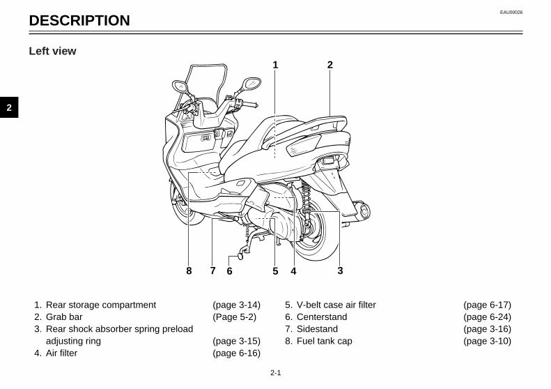
1. Rear storage compartment (page 3-14)2. Grab bar (Page 5-2)3. Rear shock absorber spring preload
adjusting ring (page 3-15)4. Air filter (page 6-16)
5. V-belt case air filter (page 6-17)6. Centerstand (page 6-24)7. Sidestand (page 3-16)8. Fuel tank cap (page 3-10)
1 2
345678
Left view
5GM-9-E0 4/13/0 9:05 PM Page 12

DESCRIPTION
1
2
3
4
5
6
7
8
9
2-2
9. Rider seat (page 3-12)10. Air flow louver (page 6-18)11. Headlight (page 6-28)12. Radiator13. Battery (page 6-26)
14. Fuse box (page 6-27)15. Coolant reservoir tank (page 6-15)16. Coolant level check window (page 6-15)17. Engine oil dipstick (page 6-11)
9
10
11
12151617 13, 14
Right view
5GM-9-E0 4/13/0 9:05 PM Page 13

1
2
3
4
5
6
7
8
9
2-3
18. Rear brake lever (page 3-10)19. Left handlebar switches (page 3-6, 3-7)20. Front storage compartment A (page 3-14)21. Digital clock (page 3-6)22. Speedometer (page 3-4)23. Coolant temperature gauge (page 3-5)
24. Fuel gauge (page 3-5)25. Right handlebar switches (page 3-7, 3-9)26. Front brake lever (page 3-9)27. Throttle grip28. Front storage compartment B (page 3-14)29. Main switch/steering lock (page 3-1)
18 19 20 21 22 23 24 25 26
272829
Controls/Instruments
EAU00026
DESCRIPTION
5GM-9-E0 4/13/0 9:05 PM Page 14

INSTRUMENT AND CONTROL FUNCTIONS
Main switch/steering lock....................................................................3-1Indicator lights ....................................................................................3-2Oil change indicator light circuit check ...............................................3-3Speedometer .....................................................................................3-4Diagnosis device ................................................................................3-4Antitheft alarm (optional) ....................................................................3-5Fuel gauge..........................................................................................3-5Coolant temperature gauge................................................................3-5Digital clock ........................................................................................3-6Handlebar switches ............................................................................3-6Headlight beam variation....................................................................3-8Front brake lever ................................................................................3-9Rear brake lever ...............................................................................3-10Fuel tank cap ....................................................................................3-10Fuel...................................................................................................3-11Catalyzer ..........................................................................................3-12Rider seat .........................................................................................3-12Rider seat adjustment.......................................................................3-13Storage compartments .....................................................................3-14Rear shock absorber adjustment......................................................3-15Carrier (optional)...............................................................................3-16Sidestand..........................................................................................3-16Sidestand switch operation check ....................................................3-17
3
5GM-9-E0 4/13/0 9:05 PM Page 15

3-1
IGNITION
P
LOCK
ONOFF
OPEN
PUSH
PUSH
EAU00029
Main switch/steering lockThe main switch controls the ignitionand lighting systems. Its operation isdescribed below.
EAU00036
ONElectrical circuits are switched on.The engine can be started. The keycannot be removed in this position.
EAU00038
OFFAll electrical circuits are switched off.The key can be removed in this posi-tion.
EAU00040
LOCKThe steering is locked in this positionand all electrical circuits are switchedoff. The key can be removed in thisposition.To lock the steering, turn the handle-bars all the way to the left. Whilepushing the key into the main switch,turn it from “OFF” to “LOCK” andremove it.To release the lock, turn the key to“OFF” while pushing.
EW000016
w
Never turn the key to “OFF” or“LOCK” when the scooter is mov-ing. The electrical circuits will beswitched off which may result inloss of control or an accident. Besure the scooter is stopped beforeturning the key to “OFF” or“LOCK”.
EAU01433
.. (Parking)The steering is locked in this position,and the taillight, license light and aux-iliary light come on, but all other cir-cuits are off. The key can beremoved in this position.To set the main switch to “.”:
1. Set the main switch to “LOCK”.2. Slightly turn the key counter-
clockwise until it stops.3. While still turning the key coun-
terclockwise, push it inward untilit snaps into place.
Do not leave the main switch in thisposition for an extended period oftime because the battery may dis-charge.
EAU00027
INSTRUMENT AND CONTROL FUNCTIONS
1
2
3
4
5
6
7
8
9
5GM-9-E0 4/13/0 9:05 PM Page 16

3-2
0.0
1.00.
1 3 42
EAU00056
Indicator lights
EAU00078
Oil change indicator light “7”When this indicator light comes on,the engine oil should be changed. Itwill come on at the initial 1,000 kmand every 3,000 km thereafter. (Referto “Engine oil replacement” for reset-ting procedures.)The oil change indicator light circuitcan be checked by the procedure onpage 3-3.
EAU00063
High beam indicator light “&” This indicator comes on when theheadlight high beam is used.
EAU03125*
Turn indicator lights “4”/“6”The corresponding indicator flasheswhen the turn signal switch is movedto the left or right.
1. Oil change indicator light “7”2. High beam indicator light “&”3. Left turn indicator light “4”4. Right turn indicator light “6”
INSTRUMENT AND CONTROL FUNCTIONS
1
2
3
4
5
6
7
8
9
5GM-9-E0 4/13/0 9:05 PM Page 17

3-3
INSTRUMENT AND CONTROL FUNCTIONS
1
2
3
4
5
6
7
8
9
EAU00076
Oil change indicator light circuit check
Electrical circuit is OK.Go ahead with riding.
Turn the main switch to “ON”.Turn the engine stop switch to “#”.
Indicator light comeson for a few secondsand then goes off.
Indicator light doesnot come on.
Ask a Yamaha dealerto inspect electrical cir-cuit.
5GM-9-E0 4/13/0 9:05 PM Page 18
3-4
INSTRUMENT AND CONTROL FUNCTIONS
1
2
3
4
5
6
7
8
9
0.0
1.00.
1 2 3
EAU01586
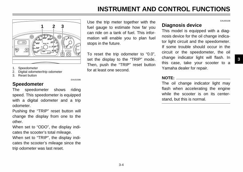
SpeedometerThe speedometer shows ridingspeed. This speedometer is equippedwith a digital odometer and a tripodometer.Pushing the “TRIP” reset button willchange the display from one to theother.When set to “ODO”, the display indi-cates the scooter’s total mileage.When set to “TRIP”, the display indi-cates the scooter’s mileage since thetrip odometer was last reset.
1. Speedometer2. Digital odometer/trip odometer3. Reset button
Use the trip meter together with thefuel gauge to estimate how far youcan ride on a tank of fuel. This infor-mation will enable you to plan fuelstops in the future.
To reset the trip odometer to “0.0”,set the display to the “TRIP” mode.Then, push the “TRIP” reset buttonfor at least one second.
EAU00108
Diagnosis deviceThis model is equipped with a diag-nosis device for the oil change indica-tor light circuit and the speedometer.If some trouble should occur in thecircuit or the speedometer, the oilchange indicator light will flash. Inthis case, take your scooter to aYamaha dealer for repair.
NOTE:The oil change indicator light mayflash when accelerating the enginewhile the scooter is on its center-stand, but this is normal.
5GM-9-E0 4/13/0 9:05 PM Page 19

3-5
INSTRUMENT AND CONTROL FUNCTIONS
1
2
3
4
5
6
7
8
9
1
EAU00109
Antitheft alarm (optional)An antitheft alarm can be equipped tothis scooter. Consult your Yamahadealer to obtain and install the alarm.
EAU00110
Fuel gaugeThis model is equipped with an elec-tric fuel gauge so the rider can moni-tor the fuel level in the fuel tank.When the needle indicates “E”(Empty), about 1.0 L remain in thefuel tank.
1. Fuel gauge
1
2
1. Coolant temperature gauge2. Red mark
EAU03124*
Coolant temperature gaugeThis gauge indicates the coolant tem-perature when the main switch is on.The engine operating temperaturewill vary with changes in weather andengine load. If the needle points tothe red mark, stop your scooter andlet the engine cool. (See page 6-15 for details.)
EC000002
cC
When the engine is overheated, donot continue riding.
5GM-9-E0 4/13/0 9:05 PM Page 20

3-6
INSTRUMENT AND CONTROL FUNCTIONS
1
2
3
4
5
6
7
8
9
1.00.
1 2 3
1. Hour button “h”2. Minute button “m”3. Digital clock
EAU03089*
Digital clockThis digital clock shows the timeregardless of the main switch posi-tion.
To set the clock1. Turn the key to “ON”.2. The time (hour) setting can be
made by pushing or holding the“h” button.
3. The time (minute) setting can bemade by pushing or holding the“m” button.
NOTE:When setting the clock after its powersource is cut by a removed battery,etc., or when pushing the “h” and “m”button simultaneously, first set thetime for 1:00 AM, then, go on to set itfor the correct time.
1
2
3
4
EAU00118
Handlebar switches
EAU00119
Pass switch “&”Press the switch to operate the pass-ing light.
EAU00121
Dimmer switchTurn the switch to “&” for the highbeam and to “%” for the low beam.
1. Pass switch “&”2. Dimmer switch3. Turn signal switch 4. Horn switch “*”
5GM-9-E0 4/13/0 9:05 PM Page 21

3-7
INSTRUMENT AND CONTROL FUNCTIONS
1
2
3
4
5
6
7
8
9
1
2
3
4
EAU00127
Turn signal switchTo signal a right-hand turn, push theswitch to “6”. To signal a left-handturn, push the switch to “4”. Oncethe switch is released it will return tothe center position. To cancel the sig-nal, push the switch in after it hasreturned to the center position.
EAU00129
Horn switch “*”Press the switch to sound the horn.
1. Pass switch “&”2. Dimmer switch3. Turn signal switch 4. Horn switch “*”
1
23
EAU00135
Light switch Turning the light switch to “'”turns on the auxiliary light, meterlights, taillight and licence light.Turning the light switch to “:” turnsthe headlight on also.
1. Engine stop switch2. Light switch3. Start switch “,”
5GM-9-E0 4/13/0 9:05 PM Page 22

3-8
INSTRUMENT AND CONTROL FUNCTIONS
1
2
3
4
5
6
7
8
9
1
2
%
%
&
&
Left Right Aux Bulb to be used Destination
2
1
1
3
1
3
2
1
Halogenbulb
Halogenbulb
Germany, Belgium, Switzerland, SpainFrance, Greece, Italy, Netherlands,Norway, Portugal, Sweden
England
3 : High beam light on 2 : Low beam light on' : Auxiliary light on 1 : Light off
12V55W
12V60/55W
12V60/55W
12V 55W
EAU00136
Headlight beam variation
NOTE:Right and left directions are those assumed from the position of a person facing the front of the scooter.
'
'
'
'
5GM-9-E0 4/13/0 9:05 PM Page 23
3-9
INSTRUMENT AND CONTROL FUNCTIONS
1
2
3
4
5
6
7
8
9
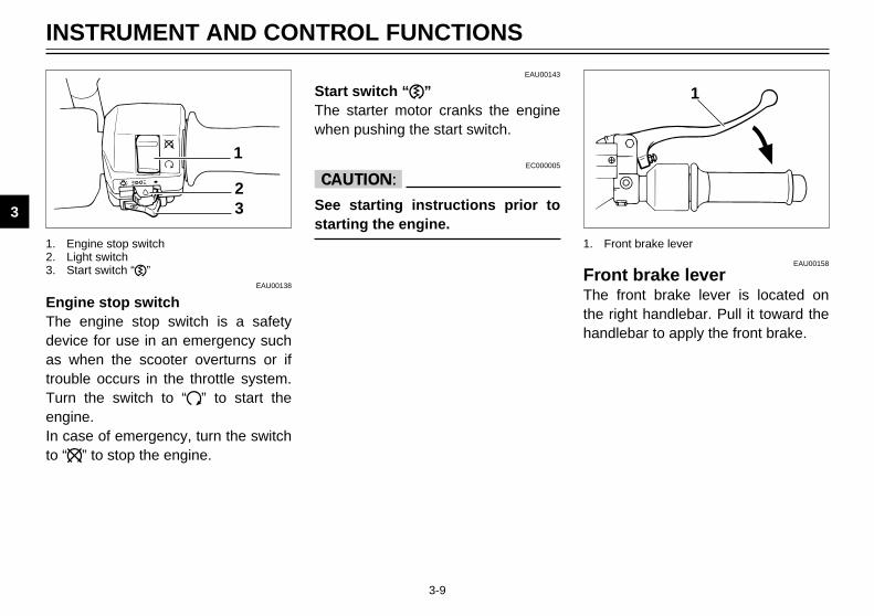
EAU00143
Start switch “,”The starter motor cranks the enginewhen pushing the start switch.
EC000005
cC
See starting instructions prior tostarting the engine.
1
1. Front brake lever
EAU00158
Front brake leverThe front brake lever is located onthe right handlebar. Pull it toward thehandlebar to apply the front brake.
1
23
1. Engine stop switch2. Light switch3. Start switch “,”
EAU00138
Engine stop switchThe engine stop switch is a safetydevice for use in an emergency suchas when the scooter overturns or iftrouble occurs in the throttle system.Turn the switch to “#” to start theengine.In case of emergency, turn the switchto “$” to stop the engine.
5GM-9-E0 4/13/0 9:05 PM Page 24

3-10
INSTRUMENT AND CONTROL FUNCTIONS
1
2
3
4
5
6
7
8
9
1
1. Rear brake lever
EAU00163
Rear brake leverThe rear brake lever is located on theleft handlebar. Pull it toward the han-dlebar to apply the rear brake.
1
2
EAU03090*
Fuel tank capThe fuel tank cap is located under thelid in front of the seat.To open the lid, slide the lever for-ward and then pull the lever up.
1. Lid2. Lever
1
To open the fuel tank cap, insert thekey into the lock and turn it clock-wise.
1. Fuel tank cap
5GM-9-E0 4/13/0 9:05 PM Page 25
3-11
INSTRUMENT AND CONTROL FUNCTIONS
1
2
3
4
5
6
7
8
9
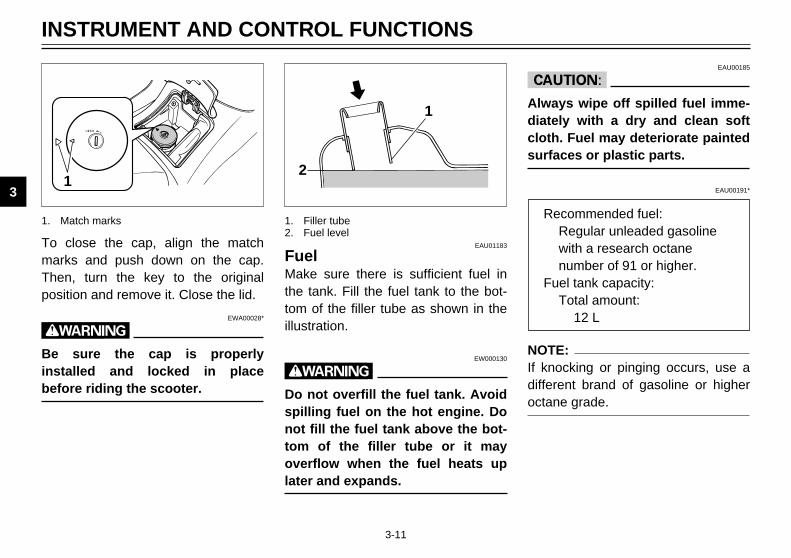
To close the cap, align the matchmarks and push down on the cap.Then, turn the key to the originalposition and remove it. Close the lid.
EWA00028*
w
Be sure the cap is properlyinstalled and locked in placebefore riding the scooter.
1
2
EAU01183
FuelMake sure there is sufficient fuel inthe tank. Fill the fuel tank to the bot-tom of the filler tube as shown in theillustration.
EW000130
w
Do not overfill the fuel tank. Avoidspilling fuel on the hot engine. Donot fill the fuel tank above the bot-tom of the filler tube or it mayoverflow when the fuel heats uplater and expands.
1. Filler tube2. Fuel level
1
1. Match marks
EAU00185
cC
Always wipe off spilled fuel imme-diately with a dry and clean softcloth. Fuel may deteriorate paintedsurfaces or plastic parts.
EAU00191*
NOTE:If knocking or pinging occurs, use adifferent brand of gasoline or higheroctane grade.
Recommended fuel:Regular unleaded gasolinewith a research octanenumber of 91 or higher.
Fuel tank capacity:Total amount:
12 L
5GM-9-E0 4/13/0 9:05 PM Page 26

3-12
INSTRUMENT AND CONTROL FUNCTIONS
1
2
3
4
5
6
7
8
9
EAU03098*
CatalyzerThis scooter is equipped with a cat-alytic converter in the muffler.
EW000128
w
The exhaust system is hot duringand directly after engine operation.Make sure the exhaust system hascooled down before making anyadjustment to or lubricating thescooter.
EC000114
cC
The following must be observed toprevent a fire hazard or other dam-ages.8 Use only unleaded gasoline.
Use of leaded gasoline willcause unrepairable damage tothe catalytic converter.
8 Never park this scooter in anarea that would cause a firehazard such as grass or othermaterials that may easily burn.
8 Do not allow the engine to idlefor very long.
IGNITION
P
LOCK
ONOFF
OPEN
PUSH
PUSH
EAU03091*
Rider seatTo open Insert the key into the main switchand turn it counterclockwise. Do notpush inward when turning the key.
To close Push the rider seat downward to theoriginal position and remove the keyfrom the main switch.
5GM-9-E0 4/13/0 9:05 PM Page 27

3-13
INSTRUMENT AND CONTROL FUNCTIONS
1
2
3
4
5
6
7
8
9
NOTE:8 Place the scooter on the center-
stand before opening the riderseat.
8 Make sure the rider seat issecurely closed before riding thescooter.
1
EAU03096*
Rider seat adjustmentThe rider seat can be adjusted tochange the riding position.
1. Rider seat
1 1
2 2
To adjust, open the rider seat andremove the bolts and collars. Slidethe seat forward or backward to thedesired position. Install the collarsand tighten the bolts securely. Thenclose the seat.
1. Bolt (×4)2. Collar (×4)
5GM-9-E0 4/13/0 9:05 PM Page 28

3-14
INSTRUMENT AND CONTROL FUNCTIONS
1
2
3
4
5
6
7
8
9
12
1. Button2. Lid
EAU03110*
Storage compartmentsFront storage compartment ATo open the storage compartmentwhen it is locked, insert the key, turnit counterclockwise, grasp the lockwhile pushing the button in.To open the storage compartmentwhen it is unlocked, simply grasp thelock while pushing the button in.To lock the storage compartment,push the lid into the original position.Insert the key and turn it clockwise.Then remove the key.
Compartment A
1
2
Front storage compartment BTo open the storage compartment,slide the lever up and pull on thelever.To close the storage compartment,push the lid into the original position.
EWA00029*
w
Do not store heavy items in thiscompartment.
1. Lever2. Lid
Compartment B
Rear storage compartmentTwo helmets can be stored in thecompartment under the seats. Whenthe rider seat is opened, the compart-ment light will come on. (See page 3-12 for rider seat opening and clos-ing procedures.)
5GM-9-E0 4/13/0 9:05 PM Page 29

3-15
INSTRUMENT AND CONTROL FUNCTIONS
1
2
3
4
5
6
7
8
9
ECA00051*
cC
Do not leave the rider seat openfor an extended period of time asthe light may cause the battery todischarge.
EWA00030*
w
Do not exceed the loading limits:Front storage compartment A: 2 kgRear storage compartment: 5 kg
EW000040
w
Always adjust each shockabsorber to the same setting.Uneven adjustment can causepoor handling and loss of stability.
Soft Stan- HarddardAdjusting
1 2 3 4 5 6 7Position
EAU00300
Rear shock absorberadjustmentEach shock absorber is equippedwith a spring preload adjusting ring.Adjust spring preload as follows.Turn the adjusting ring in direction ato increase spring preload and indirection b to decrease spring pre-load. Make sure that the appropriatenotch in the adjusting ring is alignedwith the position indicator on the rearshock absorber.
1
a
b
2
1. Spring preload adjusting ring2. Position indicator
5GM-9-E0 4/13/0 9:05 PM Page 30

3-16
INSTRUMENT AND CONTROL FUNCTIONS
1
2
3
4
5
6
7
8
9
EAU03092*
Carrier (optional)An optional carrier can be obtainedand installed at a Yamaha dealer foradding cargo or accessories to thisscooter.
EAU00330
SidestandThis model is equipped with an igni-tion circuit cut-off system. The scoot-er must not be ridden when the side-stand is down. The sidestand islocated on the left side of the frame.(Refer to page 3-17 for an explana-tion of this system.)
EW000044
w
This scooter must not be operatedwith the sidestand in the downposition. If the stand is not proper-ly retracted, it could contact theground and distract the operator,resulting in a possible loss of con-trol. Yamaha has designed intothis scooter a lockout system toassist the operator in fulfilling theresponsibility of retracting thesidestand. Please check carefullythe operating instructions listedbelow and if there is any indicationof a malfunction, return the scoot-er to a Yamaha dealer immediatelyfor repair.
5GM-9-E0 4/13/0 9:05 PM Page 31

3-17
INSTRUMENT AND CONTROL FUNCTIONS
1
2
3
4
5
6
7
8
9
1
EAU00337
Sidestand switch operationcheckCheck the operation of the sidestandswitch against the information below.
EW000046
w
88 Be sure to use the centerstandduring this inspection.
88 If improper operation is noted,consult a Yamaha dealer.
1. Sidestand switch
EW000045
w
If improper operation is noted,consult a Yamaha dealer immedi-ately.
Turn the main switch to “ON” andthe engine stop switch to “#”.
Put the sidestand up.
Push the start switch while applyingeither of the brake levers.The engine will start.
Put the sidestand down.
The sidestand switch is OK.
If the engine stalls:
5GM-9-E0 4/13/0 9:05 PM Page 32

PRE-OPERATION CHECKS
Pre-operation check list ......................................................................4-1
4
5GM-9-E0 4/13/0 9:05 PM Page 33

4-1
Owners are personally responsible for their vehicle’s condition. Your scooter’s vital functions can start to deterioratequickly and unexpectedly, even if it remains unused (for instance, if it is exposed to the elements). Any damage, fluidleak or loss of tire pressure could have serious consequences. Therefore, it is very important that, in addition to a thor-ough visual inspection, you check the following points before each ride.
EAU01114
PRE-OPERATION CHECKS
1
2
3
4
5
6
7
8
9
ITEM CHECKS PAGE
Front brake 9 Check operation, free play, fluid level and vehicle for fluid leakage. 3-9, 6-20 ~ 6-239 Fill with DOT 4 brake fluid if necessary.
Rear brake 9 Check operation, free play, fluid level and vehicle for fluid leakage. 3-10, 6-20 ~ 6-239 Fill with DOT 4 brake fluid if necessary.
Engine oil 9 Check oil level 6-11 ~ 6-139 Fill with oil if necessary.
Final gear oil 9 Check vehicle for leakage. 6-14
Throttle grip and 9 Check for smooth operation. —housing 9 Lubricate if necessary.
Wheels and tires 9 Check tire pressure, wear and damage. 6-18 ~ 6-20
Chassis fasteners 9 Make sure that all nuts, bolts, and screws are properly tightened. —9 Tighten if necessary.
Lights, signals and switches 9 Check for proper operation. 3-6 ~ 3-9, 6-28 ~ 6-32
NOTE:Pre-operation checks should be made each time the scooter is used. Such an inspection can be accomplished in a veryshort time; and the added safety it assures is more than worth the time involved.
w
If any item in the Pre-Operation Check is not working properly, have it inspected and repaired before operatingthe scooter.
EAU00340
PRE-OPERATION CHECK LIST
5GM-9-E0 4/13/0 9:05 PM Page 34

OPERATION AND IMPORTANT RIDING POINTS
Starting a cold engine.........................................................................5-1Starting off ..........................................................................................5-2Acceleration........................................................................................5-2Braking ...............................................................................................5-2Tips for reducing fuel consumption.....................................................5-3Engine break-in ..................................................................................5-3Parking ...............................................................................................5-4
5
5GM-9-E0 4/13/0 9:05 PM Page 35
5-1
EAU01118
w
1. Before riding this scooter,become thoroughly familiarwith all operating controls andtheir functions. Consult aYamaha dealer regarding anycontrol or function that you donot thoroughly understand.
2. Never start your engine or letit run for any length of time ina closed area. The exhaustfumes are poisonous and cancause loss of consciousnessand death within a short time.Always operate your scooterin an area with adequate venti-lation.
3. For safety, be sure to start theengine with the centerstanddown.
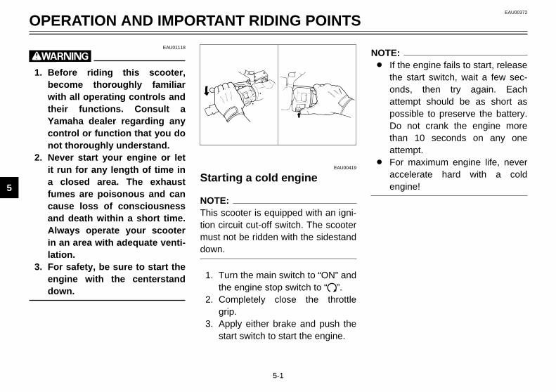
EAU00419
Starting a cold engine
NOTE:This scooter is equipped with an igni-tion circuit cut-off switch. The scootermust not be ridden with the sidestanddown.
1. Turn the main switch to “ON” andthe engine stop switch to “#”.
2. Completely close the throttlegrip.
3. Apply either brake and push thestart switch to start the engine.
NOTE:8 If the engine fails to start, release
the start switch, wait a few sec-onds, then try again. Eachattempt should be as short aspossible to preserve the battery.Do not crank the engine morethan 10 seconds on any oneattempt.
8 For maximum engine life, neveraccelerate hard with a coldengine!
EAU00372
OPERATION AND IMPORTANT RIDING POINTS
1
2
3
4
5
6
7
8
9
5GM-9-E0 4/13/0 9:05 PM Page 36
5-2
OPERATION AND IMPORTANT RIDING POINTS
1
2
3
4
5
6
7
8
9
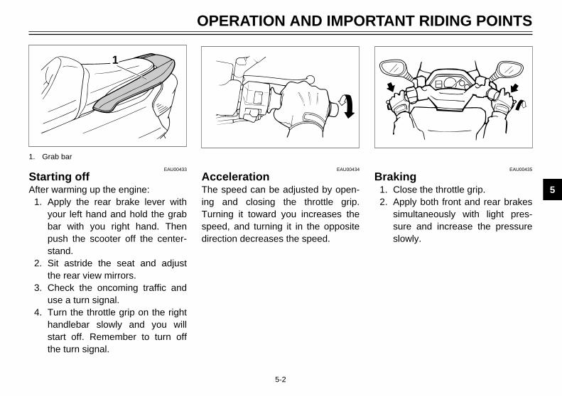
EAU00433
Starting offAfter warming up the engine:
1. Apply the rear brake lever withyour left hand and hold the grabbar with you right hand. Thenpush the scooter off the center-stand.
2. Sit astride the seat and adjustthe rear view mirrors.
3. Check the oncoming traffic anduse a turn signal.
4. Turn the throttle grip on the righthandlebar slowly and you willstart off. Remember to turn offthe turn signal.
EAU00434
AccelerationThe speed can be adjusted by open-ing and closing the throttle grip.Turning it toward you increases thespeed, and turning it in the oppositedirection decreases the speed.
EAU00435
Braking1. Close the throttle grip.2. Apply both front and rear brakes
simultaneously with light pres-sure and increase the pressureslowly.
1
1. Grab bar
5GM-9-E0 4/13/0 9:05 PM Page 37

5-3
EW000057
w
88 Avoid hard or sudden braking.It may cause the scooter toskid or overturn.
88 Be sure to apply the brakecarefully if leaning over to oneside. Improper braking couldlead to a skid.
88 Street car rails, metal plateson road construction sites,and man-hole covers becomeparticularly slippery when theyget wet. Cross them slowlyand cautiously.
88 Braking on a wet road is verydifficult.
88 Braking on a hill can be diffi-cult. Proceed slowly when rid-ing downhill.
EAU03093*
Tips for reducing fuel consumptionYour scooter’s fuel consumptiondepends to a large extent on your rid-ing style. The following tips can helpreduce fuel consumption:8 Warm up the engine before rid-
ing.8 Avoid high engine speeds during
acceleration.8 Avoid high engine speeds with
no load on the engine.8 Turn off the engine instead of let-
ting it idle for an extended lengthof time, i.e. in traffic jams, at traf-fic lights or railroad crossings.
OPERATION AND IMPORTANT RIDING POINTS
1
2
3
4
5
6
7
8
9
EAU01128
Engine break-inThere is never a more important peri-od in the life of your scooter than theperiod between zero and 1,600 km. For this reason we ask thatyou carefully read the following mate-rial. Because the engine is brandnew, you must not put an excessiveload on it for the first 1,600 km. Thevarious parts in the engine wear andpolish themselves to the correct oper-ating clearances. During this period,prolonged full throttle operation, orany condition which might result inexcessive heating of the engine,must be avoided.
5GM-9-E0 4/13/0 9:05 PM Page 38

5-4
1,600 km and beyondProceed with normal riding.
EC000049
cC
If any engine trouble should occurduring the break-in period, consulta Yamaha dealer immediately.
EAU00461
ParkingWhen parking the scooter, stop theengine and remove the ignition key.
EW000059
w
The muffler and exhaust pipe arehot. Park the scooter in a placewhere pedestrians or children arenot likely to touch the scooter. Donot park the scooter on a slope orsoft ground; the scooter may over-turn.
EC000062
cC
Never park this scooter in an areathat would cause a fire hazzardsuch as grass or other materialsthat may easily burn.
OPERATION AND IMPORTANT RIDING POINTS
1
2
3
4
5
6
7
8
9
EAU03123*
0 ~ 1,000 kmAvoid operation above 1/3 throttle.
1,000 ~ 1,600 km Avoid cruising speeds in excess of1/2 throttle.
ECA00054*
cC
After 1,000 km of operation, besure to replace the engine oil andfinal gear oil.
5GM-9-E0 4/13/0 9:05 PM Page 39

5GM-9-E0 4/13/0 9:05 PM Page 40

PERIODIC MAINTENANCE AND MINOR REPAIR
Tool kit ....................................................................6-1Periodic maintenance and lubrication .....................6-3Panel removal and installation ................................6-6Panel A ...................................................................6-6Panel B ...................................................................6-8Panel C ...................................................................6-8Spark plug.............................................................6-10Engine oil ..............................................................6-11Final gear oil replacement.....................................6-14Coolant..................................................................6-15Air filter and V-belt case filter cleaning..................6-16Air flow louver .......................................................6-18Tires ......................................................................6-18Wheels ..................................................................6-20Brake lever free play adjustment ..........................6-20Checking the front and rear brake pads................6-21Inspecting the brake fluid level..............................6-22Brake fluid replacement ........................................6-23Cable inspection and lubrication ...........................6-23Brake lever lubrication ..........................................6-23Center and sidestand lubrication ..........................6-24Front fork inspection .............................................6-24Steering inspection ...............................................6-25Wheel bearings .....................................................6-25
Battery cover removal ...........................................6-26Battery...................................................................6-26Fuse replacement .................................................6-27Headlight bulb replacement ..................................6-28Tail/brake light bulb replacement ..........................6-30Front turn signal light bulb replacement................6-30Rear turn signal light bulb replacement ................6-31License light bulb replacement .............................6-32Troubleshooting ....................................................6-33Troubleshooting chart ...........................................6-34
6
5GM-9-E0 4/13/0 9:09 PM Page 41

6-1
EAU00464
Periodic inspection, adjustment andlubrication will keep your scooter inthe safest and most efficient condi-tion possible. Safety is an obligationof the scooter owner. The mainte-nance and lubrication schedule chartshould be considered strictly as aguide to general maintenance andlubrication intervals. YOU MUST TAKE INTO CONSIDER-ATION THAT WEATHER, TERRAIN,GEOGRAPHICAL LOCATIONS, ANDA VARIETY OF INDIVIDUAL USESALL TEND TO DEMAND THATEACH OWNER ALTER THIS TIMESCHEDULE TO SHORTER INTER-VALS TO MATCH THE ENVIRON-MENT. The most important points ofscooter inspection, adjustment, andlubrication are explained in the fol-lowing pages.
EW000060
w
If you are not familiar with scooterservice, this work should be doneby a Yamaha dealer.
EAU00466
w
This scooter is designed for useon paved road surface only. If thisscooter is operated in abnormallydusty, muddy or wet conditions,the air filter should be cleaned orreplaced more frequently.Otherwise, rapid engine wear mayresult. Consult a Yamaha dealerfor proper maintenance intervals.
EAU00462
PERIODIC MAINTENANCE AND MINOR REPAIR
1
2
3
4
5
6
7
8
9
1
EAU01129
Tool kitThe tool kit is located inside of thestorage compartment. (See page 3-14 for compartment opening proce-dures.) The tools provided in theowner’s tool kit are to assist you inthe performance of periodic mainte-nance. However, some other toolssuch as a torque wrench are alsonecessary to perform the mainte-nance correctly.The service information included inthis manual is intended to provideyou, the owner, with the necessaryinformation for completing some ofyour own preventive maintenanceand minor repairs.
1. Tool kit
5GM-9-E0 4/13/0 9:09 PM Page 42

6-2
NOTE:If you do not have necessary toolsrequired during a service operation,take your scooter to a Yamaha dealerfor service.
EW000062
w
Modifications to this scooter notapproved by Yamaha may causeloss of performance, excessiveemissions, and render it unsafe foruse. Consult a Yamaha dealerbefore attempting any changes.
PERIODIC MAINTENANCE AND MINOR REPAIR
1
2
3
4
5
6
7
8
9
5GM-9-E0 4/13/0 9:09 PM Page 43

6-3
PERIODIC MAINTENANCE AND MINOR REPAIR
1
2
3
4
5
6
7
8
9
EAU00473
PERIODIC MAINTENANCE AND LUBRICATIONInitial EVERY ANNUAL
No. ITEM CHECKS AND MAINTENANCE JOB(1,000 km) 10,000 km 20,000 km CHECK
1 * Fuel line 9 Check fuel hoses and vacuum hose for cracks or damage. √ √9 Replace if necessary.
2 Fuel filter 9 Check condition. √9 Replace if necessary.
3 Spark plug 9 Check condition. √9 Clean, regap or replace if necessary.
4 * Valves 9 Check valve clearance. √9 Adjust if necessary.
5 Air filter 9 Clean or replace if necessary. √6 V-belt case air filter 9 Clean or replace if necessary. √
9 Check operation, fluid level and vehicle for fluid leakage.
7 * Front brake (See NOTE on page 6-5.) √ √ √9 Correct accordingly.9 Replace brake pads if necessary.
9 Check operation, fluid level and vehicle for fluid leakage.
8 * Rear brake (See NOTE on page 6-5.) √ √ √9 Correct accordingly.9 Replace brake pads if necessary.
9 * Brake hoses 9 Check for cracks or damage. √ √9 Replace if necessary.
10 * Wheels 9 Check balance, runout and for damage. √9 Rebalance or replace if necessary.
9 Check tread depth and for damage.
11 * Tires 9 Replace if necessary. √9 Check air pressure.9 Correct if necessary.
12 * Wheel bearings 9 Check bearing for looseness or damage. √9 Replace if necessary.
5GM-9-E0 4/13/0 9:09 PM Page 44

6-4
PERIODIC MAINTENANCE AND MINOR REPAIR
1
2
3
4
5
6
7
8
9
Initial EVERY ANNUALNo. ITEM CHECKS AND MAINTENANCE JOB
(1,000 km) 10,000 km 20,000 km CHECK9 Check bearing play and steering for roughness. √ √
13 * Steering bearings 9 Correct accordingly.
9 Lubricate with lithium soap base grease. √
14 * Chassis fasteners 9Make sure that all nuts, bolts and screws are properly tightened. √ √9 Tighten if necessary.
15 Sidestand/centerstand 9 Check operation. √ √9 Lubricate and repair if necessary.
16 * Sidestand switch 9 Check operation. √ √ √9 Replace if necessary.
17 * Front fork 9 Check operation and for oil leakage. √9 Correct accordingly.
18 * Rear shock absorber 9 Check operation and shock absorbers for oil leakage. √assemblies 9 Replace shock absorber assembly if necessary.
19 * Carburetor 9 Check engine idling speed and starter operation. √ √ √9 Adjust if necessary.
9 Check oil level and vehicle for oil leakage. 20 Engine oil 9 Correct if necessary. √ Replace every 3,000 km
9 Change. (Warm engine before draining.)
21 * Engine oil strainer 9 Clean or replace if necessary. √ Clean or replace every 6,000 km
9 Check coolant level and vehicle for coolant leakage. √ √22 * Cooling system 9 Correct if necessary.
9 Change coolant. √
23 Final gear oil 9 Check oil level and vehicle for oil leakage. √ √9 Change oil.
24 * V-belt 9 Replace. √
5GM-9-E0 4/13/0 9:09 PM Page 45

6-5
PERIODIC MAINTENANCE AND MINOR REPAIR
1
2
3
4
5
6
7
8
9
* Since these items require special tools, data and technical skills, they should be serviced by a Yamaha dealer.
EAU03206
NOTE:8 The annual checks must be performed every year, except if a 10,000 km or 20,000 km maintenance is performed
instead.8 The air filter needs more frequent service if you are riding in unusually wet or dusty areas.8 Hydraulic brake service8 Regularly check and, if necessary, correct the brake fluid level. 8 Every two years replace the internal components of the brake master cylinder and caliper, and change the brake
fluid.8 Replace the brake hoses every four years and if cracked or damaged.
Initial EVERY ANNUALNo. ITEM CHECKS AND MAINTENANCE JOB
(1,000 km) 10,000 km 20,000 km CHECK
25 * Front/Rear brake switch 9 Check operation. √ √ √9 Adjust or replace if necessary.
26 Moving parts and cables 9 Lubricate if necessary. √ √9 Check all lights, signals and switches function.
27 * Electrical components 9 Correct if necessary. √ √ √9 Adjust headlight beam if necessary.
5GM-9-E0 4/13/0 9:09 PM Page 46

6-6
1
1
EAU01122
Panel removal and installationThe panels illustrated need to beremoved to perform some of themaintenance described in this chap-ter.Refer to this section each time apanel has to be removed or rein-stalled.
1. Panel A 1. Panel C
PERIODIC MAINTENANCE AND MINOR REPAIR
1
2
3
4
5
6
7
8
9
1
1. Panel B
5GM-9-E0 4/13/0 9:09 PM Page 47

6-7
2 1
1. Tab (×2)2. Slot (×2)
To install1. Insert the tabs on the panel into
the slots as shown, and thenpush the panel in until it snapsinto place.
2. Install the screws.
PERIODIC MAINTENANCE AND MINOR REPAIR
1
2
3
4
5
6
7
8
9
EAU03114*
Panel ATo remove
1. Remove the screws.
2. Pull the panel back as shown.
1 1
1. Screw (×2)
5GM-9-E0 4/13/0 9:09 PM Page 48
6-8
1
2
EAU03121*
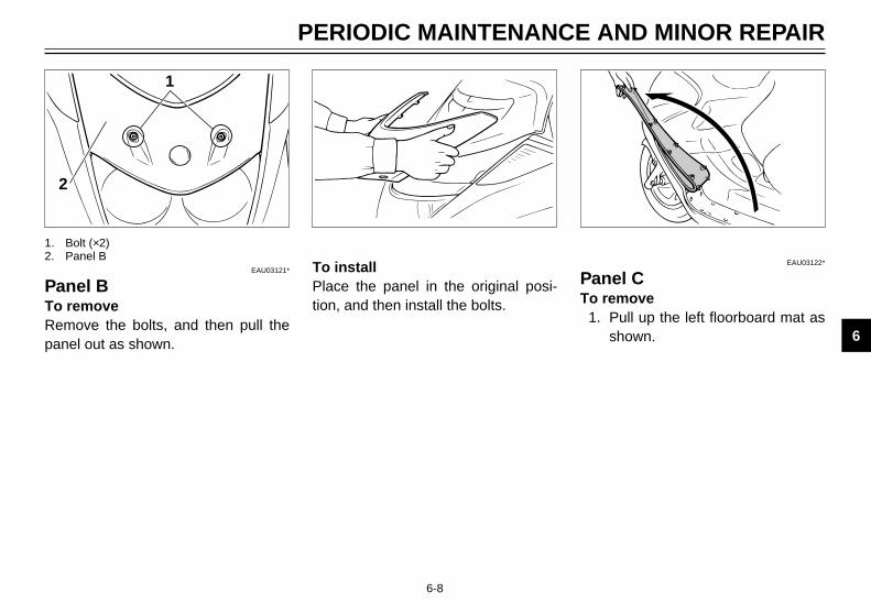
Panel BTo removeRemove the bolts, and then pull thepanel out as shown.
To installPlace the panel in the original posi-tion, and then install the bolts.
EAU03122*
Panel CTo remove
1. Pull up the left floorboard mat asshown.
1. Bolt (×2)2. Panel B
PERIODIC MAINTENANCE AND MINOR REPAIR
1
2
3
4
5
6
7
8
9
5GM-9-E0 4/13/0 9:09 PM Page 49

6-9
2
1
1
2. Remove the panel screws.
1. Screw (×4)2. Panel C
3. Pull the panel out as shown. To install1. Insert the tabs on the panel into
the slots as shown.2. Install the panel screws.
PERIODIC MAINTENANCE AND MINOR REPAIR
1
2
3
4
5
6
7
8
9
5GM-9-E0 4/13/0 9:09 PM Page 50

6-10
PERIODIC MAINTENANCE AND MINOR REPAIR
1
2
3
4
5
6
7
8
9
1
1
EAU01833
Spark plugRemoval
1. Remove the spark plug cap.
2. Use the spark plug wrench in thetool kit to remove the spark plugas shown.
1. Spark plug cap 1. Spark plug wrench
InspectionThe spark plug is an importantengine component and is easy toinspect. The condition of the sparkplug can indicate the condition of theengine.The ideal color on the white insulatoraround the center electrode is amedium-to-light tan color for a scoot-er that is being ridden normally.Do not attempt to diagnose suchproblems yourself. Instead, take thescooter to a Yamaha dealer. Youshould periodically remove andinspect the spark plug because heatand deposits will cause any sparkplug to slowly break down and erode.If electrode erosion becomes exces-sive, or if carbon and other depositsare excessive, you should replacethe spark plug with the specified plug.
Specified spark plug:DR8EA (NGK)
5GM-9-E0 4/13/0 9:09 PM Page 51

6-11
PERIODIC MAINTENANCE AND MINOR REPAIR
1
2
3
4
5
6
7
8
9
NOTE:If a torque wrench is not availablewhen you are installing a spark plug,a good estimate of the correct torqueis 1/4 to 1/2 turn past finger tight.Have the spark plug tightened to thespecified torque as soon as possible.
4. Install the spark plug cap.
1
1. Spark plug gap
Spark plug gap:0.6 ~ 0.7 mm
Tightening torque:Spark plug:
17.5 Nm (1.75 m0kg)
Installation1. Measure the electrode gap with
a wire thickness gauge and, ifnecessary, adjust the gap tospecification.
2. Clean the gasket surface. Wipeoff any grime from the threads.
3. Install the spark plug and tightenit to the specified torque.
12
1
EAU03119*
Engine oilOil level measurement
1. Place the scooter on the center-stand. Warm up the engine forseveral minutes.
NOTE:8 Be sure the scooter is positioned
straight up when checking the oillevel. A slight tilt toward the sidecan result in false readings.
8 When adding oil, be careful notto overfill the engine; the oil levelrises faster starting from the halflevel portion on the dipstick.
1. Oil filler cap2. Dipstick
5GM-9-E0 4/13/0 9:09 PM Page 52

6-12
PERIODIC MAINTENANCE AND MINOR REPAIR
1
2
3
4
5
6
7
8
9
1
1. Drain bolt
2. Stop the engine and remove theoil filler cap.
NOTE:Wait a few minutes until the oil settlesbefore checking.
3. Wipe the oil off the dipstick.Insert the dipstick back into theengine oil filler hole, but do notscrew it in. Then pull out the dip-stick again.The oil level should be betweenthe minimum and maximummarks on the dipstick. If the levelis low, add sufficient oil throughthe engine oil filler hole to reachthe specified level.
Engine oil replacement1. Warm up the engine for a few
minutes.2. Stop the engine. Place an oil pan
under the engine to catch the oiland remove the oil filler cap.
3. Remove the drain bolt and drainthe oil.
1 2
4. Check the washer and replace itif damaged.
5. Install the washer and drain bolt,and then tighten the drain bolt tothe specified torque.
NOTE:Make sure the washer is seatedproperly.
1. Drain bolt2. Washer
Tightening torque:Drain bolt:
20 Nm (2.0 m0kg)
21
1. Maximum level mark2. Minimum level mark
5GM-9-E0 4/13/0 9:09 PM Page 53

6-13
PERIODIC MAINTENANCE AND MINOR REPAIR
1
2
3
4
5
6
7
8
9
1
6. Fill the engine with oil and installthe oil filler cap.
EC000030
cC
88 Do not put in any chemicaladditives or use oils with agrade of CD or higher. Also, besure not to use oils labeled“ENERGY CONSERVING II” orhigher.
88 Be sure no foreign materialenters the crankcase.
7. Start the engine and warm it upfor a few minutes. While warmingup, check for oil leakage. If oilleakage is found, stop the engineimmediately and check for thecause.
Resetting the oil change indicatorlight
1. Turn the key to “ON”.2. Push and hold in the reset button
for 2 ~ 5 seconds.3. Release the reset button and the
oil change indicator light will gooff.
1. Oil change indicator light reset button
Recommended oil:See page 8-1.
Oil quantity:Total amount: 1.4 LPeriodic oil change: 1.2 L
NOTE:If the oil is changed before the oilchange indicator light comes on (i.e.before the 3,000-km oil change inter-val is reached), be sure to reset itafter changing the oil, so that it willcome on at the correct time to indi-cate the next 3,000-km oil replace-ment.
To reset the oil change indicator lightbefore it comes on, follow steps 1and 2. Then, release the reset buttonand the oil change indicator light willcome on for 1.4 seconds. If it doesnot come on for 1.4 seconds, repeatthe procedure.
5GM-9-E0 4/13/0 9:09 PM Page 54

6-14
PERIODIC MAINTENANCE AND MINOR REPAIR
1
2
3
4
5
6
7
8
9
1
1
1. Final gear oil filler cap 1. Drain bolt
EAU03120*
Final gear oil replacement1. Put the scooter on the center-
stand.2. Place an oil pan under the final
gear case to catch the oil.3. Remove the oil filler cap and the
drain bolt to drain the oil.4. Install and tighten the drain bolt
to the specified torque.
5. Fill the gear case with the recom-mended oil.
EW000066
w
Do not let foreign material enterthe final gear case. Be sure oildoes not get on the tire or wheel.
Tightening torque:Drain bolt:
22 Nm (2.2 m0kg)
Recommended final gear oil:SAE 10W30 type SE motor oil
Final gear case capacity:0.25 L
6. Install the oil filler cap.7. After replacing the final gear oil,
be sure to check for oil leakage.
5GM-9-E0 4/13/0 9:09 PM Page 55

6-15
PERIODIC MAINTENANCE AND MINOR REPAIR
1
2
3
4
5
6
7
8
9
1
2
1
EAU01587
CoolantThe coolant reservoir tank is locatedunder the battery cover. (See page 6-26 for battery cover removal proce-dures.)Check the coolant level in the reser-voir tank when the engine is cold.The coolant level will vary with enginetemperature. The coolant level is sat-isfactory if it is between the minimumand maximum marks on the tank. Ifthe coolant level is at or below theminimum mark, fill with tap water (softwater) to bring the level up to themaximum mark.Have a Yamaha dealer change the
coolant every two years.If your scooter overheats, see page 6-35 for details.
EW000067
w
Do not remove the radiator capwhen the engine is hot.
EC000080
cC
Hard water or salt water is harmfulto the engine. You may use dis-tilled water if you can’t get softwater.
1. Maximum level mark2. Minimum level mark
1. Coolant reservoir tank cap
NOTE:The radiator fan operation is com-pletely automatic. It is switched on oroff according to the coolant tempera-ture in the radiator.
Reservoir tank capacity:0.4 L
5GM-9-E0 4/13/0 9:09 PM Page 56

6-16
PERIODIC MAINTENANCE AND MINOR REPAIR
1
2
3
4
5
6
7
8
9
1
2
2 1
1. Air filter case cover2. Screw (×5)
1. Air filter element
EAU03113*
Air filter and V-belt case airfilter cleaningThe air filter and V-belt case air filtershould be cleaned at the specifiedintervals.They should be cleaned more fre-quently if you are riding in unusuallywet or dusty areas.
1. Place the scooter on the center-stand.
2. Remove panel C. (See page 6-8for panel removal and installationprocedures.)
3. Remove the air filter case coverby removing the screws.
4. Remove the air filter element andwash it gently, but thoroughly insolvent. If the air filter element isdamaged, replace it.
5. Squeeze out the excess solventand allow it to dry.
6. Apply oil to the entire surface ofthe air filter element andsqueeze out the excess oil. Itshould be damp, but not drip-ping.
7. Install the air filter element andthe air filter case cover.
Recommended oil:Engine oil
5GM-9-E0 4/13/0 9:09 PM Page 57

6-17
PERIODIC MAINTENANCE AND MINOR REPAIR
1
2
3
4
5
6
7
8
9
21
1
1. V-belt case air filter cover2. Screw (×3)
1. V-belt case air filter
8. Remove the V-belt case air filtercover by removing the screws.
9. Remove the V-belt case air filterelement and blow out the dirtwith compressed air from theinner side of the V-belt case airfilter element. If the V-belt caseair filter element is damaged,replace it.
10. Install the V-belt case air filterelement with the colored sidefacing outward, and then installthe V-belt case air filter cover.
EC000092
cC
88 Make sure both filters areproperly seated in their cases.
88 The engine should never berun without the filtersinstalled.
11. Install panel C.
5GM-9-E0 4/13/0 9:09 PM Page 58

6-18
PERIODIC MAINTENANCE AND MINOR REPAIR
1
2
3
4
5
6
7
8
9
EAU00675
TiresTo ensure maximum performance,long service and safe operation, notethe following:Tire air pressureAlways check and adjust the tirepressure before operating the scoot-er.
EAU03094*
Air flow louverOpening the air flow louver may helpreduce air turbulence.To open the air flow louver, move thelever in direction a.To close the air flow louver, move thelever in direction b.
ECA00049*
cC
Be sure to close the louver whenriding in the rain and when wash-ing the scooter.
12
b
3
a
1. Louver2. Air inlet3. Lever
EW000082
w
Tire inflation pressure should bechecked and adjusted when thetemperature of the tire equals theambient air temperature. Tire infla-tion pressure must be adjustedaccording to total weight of cargo,rider, passenger, and accessories(fairing, saddlebags, etc. ifapproved for this model), and vehi-cle speed.
* Load is the total weight of cargo, rider, passengerand accessories.
Maximum load* 187 kg
Cold tire pressure Front Rear
175 kPa 200 kPaUp to 90 kg (1.75 kg/cm2, (2.00 kg/cm2,
1.75 bar) 2.00 bar)
90 kg load ~200 kPa 225 kPa
maximum load*(2.00 kg/cm2, (2.25 kg/cm2,
2.00 bar) 2.25 bar)
5GM-9-E0 4/13/0 9:09 PM Page 59
6-19
PERIODIC MAINTENANCE AND MINOR REPAIR
1
2
3
4
5
6
7
8
9
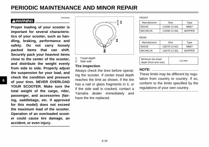
EW000083
w
Proper loading of your scooter isimportant for several characteris-tics of your scooter, such as han-dling, braking, performance andsafety. Do not carry looselypacked items that can shift.Securely pack your heaviest itemsclose to the center of the scooter,and distribute the weight evenlyfrom side to side. Properly adjustthe suspension for your load, andcheck the condition and pressureof your tires. NEVER OVERLOADYOUR SCOOTER. Make sure thetotal weight of the cargo, rider,passenger, and accessories (fair-ing, saddlebags, etc. if approvedfor this model) does not exceedthe maximum load of the scooter.Operation of an overloaded scoot-er could cause tire damage, anaccident, or even injury.
Manufacturer Size Type
INOUE 110/90-12 64L MB67
MICHELIN 110/90-12 64L BOPPER
FRONT
Manufacturer Size Type
INOUE 130/70-12 62L MB67
MICHELIN 130/70-12 62L BOPPER
REAR
Minimum tire tread1.6 mm
depth (front and rear)
NOTE:These limits may be different by regu-lation from country to country. If so,conform to the limits specified by theregulations of your own country.
1
2
Tire inspectionAlways check the tires before operat-ing the scooter. If center tread depthreaches the limit as shown, if the tirehas a nail or glass fragments in it, orif the side wall is cracked, contact aYamaha dealer immediately andhave the tire replaced.
1. Tread depth2. Side wall
5GM-9-E0 4/13/0 9:09 PM Page 60

6-20
PERIODIC MAINTENANCE AND MINOR REPAIR
1
2
3
4
5
6
7
8
9
EW000079
w
Operating the scooter with exces-sively worn tires decrease ridingstability and can lead to loss ofcontrol. Have excessively worntires replaced by a Yamaha dealerimmediately. Brakes, tires, andrelated wheel parts replacementshould be left to a Yamaha ServiceTechnician.
EAU00687
WheelsTo ensure maximum performance,long service, and safe operation, notethe following:8 Always inspect the wheels
before a ride. Check for cracks,bends, or warpage of the wheels.If any abnormal condition existsin a wheel, consult a Yamahadealer. Do not attempt evensmall repairs to the wheel. If awheel is deformed or cracked, itmust be replaced.
8 Tires and wheels should be bal-anced whenever either one ischanged or replaced. Failure tohave a wheel balanced canresult in poor performance,adverse handling characteristics,and shortened tire life.
8 Ride at moderate speeds afterchanging a tire since the tire sur-face must first be broken in for itto develop its optimal character-istics.
1
2
a
b
3
EAU00703
Brake lever free playadjustmentThe front brake lever free play shouldbe adjusted to 2 ~ 5 mm at the brakelever end.
1. Locknut2. Adjusting bolt3. Free play
FRONT
5GM-9-E0 4/13/0 9:09 PM Page 61

6-21
PERIODIC MAINTENANCE AND MINOR REPAIR
1
2
3
4
5
6
7
8
9
1
2
b
a
3
The rear brake lever free play shouldbe adjusted to 2 ~ 5 mm at the brakelever end.Loosen the locknut and turn theadjusting bolt in direction a toincrease free play and in direction bto decrease free play.Be sure to tighten the locknut afteradjusting.
EW000101
w
When it is impossible to make theproper adjustment, ask a Yamahadealer.
1. Locknut2. Adjusting bolt3. Free play
REAR
1
Inspect each wear indicator grooveand, as soon as one of them hasalmost worn away, ask a Yamahadealer to replace the brake pads as aset.
1. Wear indicator groove (×2)
REAR
1
1. Wear indicator groove (×2)
FRONT
EAU01314
Checking the front and rearbrake padsEach brake pad is provided with awear indicator groove, which allowschecking the brake pad for wear with-out disassembling the brake.
5GM-9-E0 4/13/0 9:09 PM Page 62

6-22
PERIODIC MAINTENANCE AND MINOR REPAIR
1
2
3
4
5
6
7
8
9
1
EAU00731
Inspecting the brake fluidlevelInsufficient brake fluid may let airenter the brake system, possiblycausing the brakes to become inef-fective.Before riding, check that the brakefluid is above the minimum level andreplenish when necessary.Observe these precautions:8 When checking the fluid level,
make sure the top of the mastercylinder is level by turning thehandlebars.
1. Minimum level mark
FRONT
1
8 Use only the designated qualitybrake fluid. Otherwise, the rub-ber seals may deteriorate, caus-ing leakage and poor brake per-formance.
8 Refill with the same type of brakefluid. Mixing fluids may result in aharmful chemical reaction andlead to poor brake performance.
1. Minimum level mark
REAR
Recommended brake fluid:DOT 4
8 Be careful that water does notenter the master cylinder whenrefilling. Water will significantlylower the boiling point of the fluidand may result in vapor lock.
8 Brake fluid may deteriorate paint-ed surfaces or plastic parts.Always clean up spilled fluidimmediately.
8 Have a Yamaha dealer checkthe cause if the brake fluid levelgoes down.
5GM-9-E0 4/13/0 9:09 PM Page 63
6-23
PERIODIC MAINTENANCE AND MINOR REPAIR
1
2
3
4
5
6
7
8
9
EAU00742
Brake fluid replacementThe brake fluid should be replacedonly by trained Yamaha service per-sonnel. Have the Yamaha dealerreplace the following componentsduring periodic maintenance or whenthey are damaged or leaking:8 oil seals (every two years)8 brake hoses (every four years)
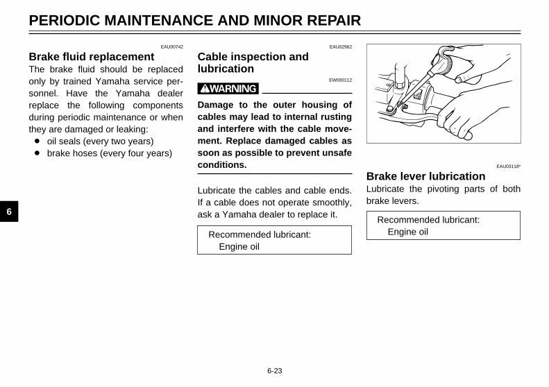
EAU02962
Cable inspection andlubrication
EW000112
w
Damage to the outer housing ofcables may lead to internal rustingand interfere with the cable move-ment. Replace damaged cables assoon as possible to prevent unsafeconditions.
Lubricate the cables and cable ends.If a cable does not operate smoothly,ask a Yamaha dealer to replace it.
Recommended lubricant:Engine oil
EAU03118*
Brake lever lubricationLubricate the pivoting parts of bothbrake levers.
Recommended lubricant:Engine oil
5GM-9-E0 4/13/0 9:09 PM Page 64

6-24
PERIODIC MAINTENANCE AND MINOR REPAIR
1
2
3
4
5
6
7
8
9
EAU02965
Center and sidestand lubricationLubricate the pivoting and matingjoints.Check to see that the center andsidestand move up and downsmoothly.
EW000114
w
If the center and/or sidestand doesnot move smoothly, consult aYamaha dealer.
Recommended lubricant:Engine oil
EAU02939
Front fork inspectionVisual check
EW000115
w
Securely support the scooter sothere is no danger of it falling over.
Check for scratches or damage onthe inner tube and excessive oil leak-age from the front fork. Operation check
1. Place the scooter on a levelplace.
2. Hold the scooter in an uprightposition and apply the frontbrake.
3. Push down hard on the handle-bars several times and check ifthe fork rebounds smoothly.
EC000098
cC
If any damage or unsmooth move-ment is found with the front fork,consult a Yamaha dealer.
5GM-9-E0 4/13/0 9:09 PM Page 65

6-25
PERIODIC MAINTENANCE AND MINOR REPAIR
1
2
3
4
5
6
7
8
9
EAU00794
Steering inspectionPeriodically inspect the condition ofthe steering. Worn out or loose steer-ing bearings may be dangerous.Place a stand under the engine toraise the front wheel off the ground.Hold the lower end of the front forksand try to move them forward andbackward. If any free play can be felt,ask a Yamaha dealer to inspect andadjust the steering. Inspection is eas-ier if the front wheel is removed.
EAU01144
Wheel bearingsIf there is play in the front or rearwheel hub or if the wheel does notturn smoothly, have a Yamaha dealerinspect the wheel bearings.
EW000115
w
Securely support the scooter sothere is no danger of it falling over.
5GM-9-E0 4/13/0 9:09 PM Page 66

6-26
PERIODIC MAINTENANCE AND MINOR REPAIR
1
2
3
4
5
6
7
8
9
EAU00796
Battery cover removalPull up the right floorboard mat asshown. Then remove the screws andthe battery cover.
NOTE:The battery cover needs to beremoved to access the fuse box andthe coolant reservoir tank cap.
1
2
1. Screw (×2)2. Battery cover
1
2
1. Coolant reservoir tank cap2. Fuse box (×2)
1
1. Battery
EAU01271
BatteryThis scooter is equipped with asealed-type battery. Therefore it isnot necessary to check the elec-trolyte or fill the battery with distilledwater.8 If the battery seems to have dis-
charged, consult a Yamaha deal-er.
8 If the scooter is equipped withoptional electrical accessories,the battery tends to dischargemore quickly, so be sure torecharge it periodically.
5GM-9-E0 4/13/0 9:09 PM Page 67

6-27
PERIODIC MAINTENANCE AND MINOR REPAIR
1
2
3
4
5
6
7
8
9
EW000116
w
Battery electrolyte is poisonousand dangerous, causing severeburns, etc. It contains sulfuricacid. Avoid contact with skin, eyesor clothing.ANTIDOTE:88 EXTERNAL: Flush with water.88 INTERNAL: Drink large quanti-
ties of water or milk. Followwith milk of magnesia, beatenegg, or vegetable oil. Call aphysician immediately.
88 EYES: Flush with water for 15minutes and get prompt med-ical attention.
Batteries produce explosivegases. Keep sparks, flame, ciga-rettes etc., away. Ventilate whencharging or using in an enclosedspace. Always shield your eyeswhen working near batteries.KEEP OUT OF REACH OF CHIL-DREN.
Battery storageWhen the scooter is not used for amonth or longer, remove the battery,fully charge it and store it in a cool,dry place.
EC000102
cC
88 Completely recharge the bat-tery before storing. Storing adischarged battery can causepermanent battery damage.
88 Use a battery chargerdesigned for a sealed-type(MF) battery. Using a conven-tional battery charger willcause battery damage. If youdo not have a sealed-type bat-tery charger, contact yourYamaha dealer.
88 Always make sure the connec-tions are correct when rein-stalling the battery.
456
7
1
32
7
8
EAU03095*
Fuse replacementThe main fuse and fuse box arelocated beside the battery.
1. Remove the battery cover byremoving the screws.
1. Main fuse2. Clock fuse (back up)3. Radiator fan fuse4. Ignition fuse5. Headlight fuse6. Signaling system fuse7. Spare fuse (×4)8. Spare main fuse
5GM-9-E0 4/13/0 9:09 PM Page 68

6-28
PERIODIC MAINTENANCE AND MINOR REPAIR
1
2
3
4
5
6
7
8
9
2. If a fuse is blown, turn off theignition switch and the switch ofthe circuit in question. Install anew fuse of specified amperage.Turn on the switches, and see ifthe electrical device operates. Ifthe fuse immediately blowsagain, consult a Yamaha dealer.
EC000103
cC
Do not use fuses of higher amper-age rating than those recommend-ed. Substitution of a fuse ofimproper rating can cause exten-sive electrical system damage andpossibly a fire.
Specified fuses:Main fuse: 30 AClock fuse (back up): 10 ARadiator fan fuse: 4 AIgnition fuse: 7.5 AHeadlight fuse: 15 ASignaling system fuse: 15 A
EAU03112*
Headlight bulb replacementThis scooter is equipped with quartzbulb headlights.If a headlight bulb burns out, replacethe bulb as follows:
1. Place the scooter on the center-stand.
2. Remove panel B. (See page 6-8for panel removal and installationprocedures.)
1
2
3. Disconnect the headlight couplerand remove the bulb holdercover.
1. Coupler (×2)2. Bulb holder cover (×2)
5GM-9-E0 4/13/0 9:09 PM Page 69

6-29
PERIODIC MAINTENANCE AND MINOR REPAIR
1
2
3
4
5
6
7
8
9
1
4. Unhook the bulb holder toremove the defective bulb.
EW000119
w
Keep flammable products and yourhands away from a bulb while it ison, as it is hot. Do not touch a bulbuntil it cools down.
1. Bulb holder (×2)
5. Put a new bulb into position andsecure it in place with the bulbholder.
EC000105
cC
Avoid touching the glass part of abulb. Keep it free from oil; other-wise, the transparency of theglass, life of the bulb, and lumi-nous flux will be adversely affect-ed. If oil gets on a bulb, thoroughlyclean it with a cloth moistenedwith alcohol or lacquer thinner.
6. Install the bulb holder cover andconnect the headlight coupler.
7. Install the panel.If necessary, ask a Yamaha dealer toadjust the headlight beam.
1
1. Don’t touch
5GM-9-E0 4/13/0 9:09 PM Page 70

6-30
PERIODIC MAINTENANCE AND MINOR REPAIR
1
2
3
4
5
6
7
8
9
EAU03115*
Tail/brake light bulb replacement
1. Place the scooter on the center-stand.
2. Remove panel A. (See page 6-6for panel removal and installationprocedures.)
1
1. Bulb socket (×2)
3. Turn the tail/brake light bulbsocket counterclockwise toremove it.
4. Remove the defective bulb bypushing it inward and turning itcounterclockwise.
5. Install a new bulb by pushing itinward and turning it clockwise.
6. Install the tail/brake light bulbsocket into the original positionand turn it clockwise.
7. Install the panel.
EAU03111*
Front turn signal light bulbreplacement
1. Place the scooter on the center-stand.
2. Remove panel B. (See page 6-8for panel removal and installationprocedures.)
5GM-9-E0 4/13/0 9:09 PM Page 71

6-31
PERIODIC MAINTENANCE AND MINOR REPAIR
1
2
3
4
5
6
7
8
9
1
3. Remove the front turn signal lightbulb socket by turning it counter-clockwise.
4. Remove the defective bulb bypushing it inward and turning itcounterclockwise.
5. Install a new bulb by pushing itinward and turning it clockwise.
6. Install the front turn signal lightbulb socket into the original posi-tion and turn it clockwise.
7. Install the panel.
1. Bulb socket
EAU03116*
Rear turn signal light bulbreplacement
1. Place the scooter on the center-stand.
2. Remove panel A. (See page 6-6for panel removal and installationprocedures.)
1
1. Bulb socket
3. Turn the rear turn signal light bulbsocket counterclockwise toremove it.
4. Pull out the defective bulb.5. Install a new bulb by pushing it
inward.6. Install the rear turn signal light
bulb socket into the original posi-tion and turn it clockwise.
7. Install the panel.
5GM-9-E0 4/13/0 9:09 PM Page 72
6-32
PERIODIC MAINTENANCE AND MINOR REPAIR
1
2
3
4
5
6
7
8
9
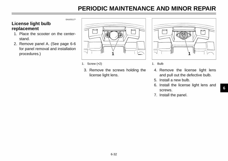
EAU03117*
License light bulb replacement
1. Place the scooter on the center-stand.
2. Remove panel A. (See page 6-6for panel removal and installationprocedures.) 1
3. Remove the screws holding thelicense light lens.
1. Screw (×2)
1
4. Remove the license light lensand pull out the defective bulb.
5. Install a new bulb.6. Install the license light lens and
screws.7. Install the panel.
1. Bulb
5GM-9-E0 4/13/0 9:09 PM Page 73

6-33
PERIODIC MAINTENANCE AND MINOR REPAIR
1
2
3
4
5
6
7
8
9
EAU01008
TroubleshootingAlthough Yamaha scooter receive arigid inspection before shipment fromthe factory, trouble may occur duringoperation.Any problem in the fuel, compres-sion, or ignition systems can causepoor starting and loss of power. Thetroubleshooting chart describes aquick, easy procedure for makingchecks.If your scooter requires any repair,bring it to a Yamaha dealer. Theskilled technicians at a Yamaha deal-ership have the tools, experience,and know-how to properly serviceyour scooter. Use only genuineYamaha parts on your scooter.Imitation parts may look like Yamahaparts, but they are often inferior.Consequently, they have a shorterservice life and can lead to expensiverepair bills.
5GM-9-E0 4/13/0 9:09 PM Page 74
6-34
PERIODIC MAINTENANCE AND MINOR REPAIR
1
2
3
4
5
6
7
8
9
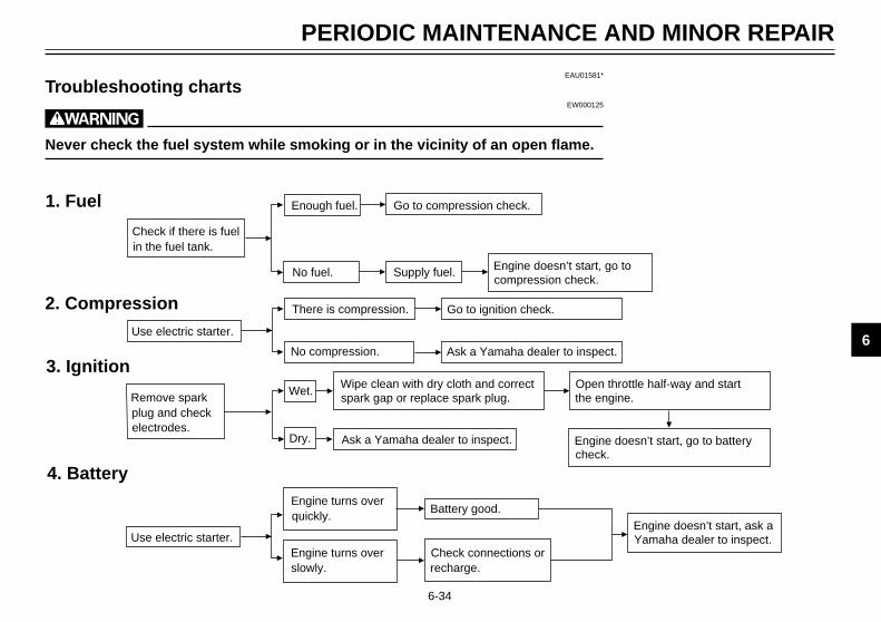
EAU01581*
Troubleshooting chartsEW000125
w
Never check the fuel system while smoking or in the vicinity of an open flame.
1. Fuel
2. Compression
3. Ignition
4. Battery
Remove spark
There is compression. Go to ignition check.
No compression. Ask a Yamaha dealer to inspect.
Use electric starter.
Wet.
Dry.
Wipe clean with dry cloth and correct Open throttle half-way and start
Ask a Yamaha dealer to inspect.
Check if there is fuel
Enough fuel.
No fuel.
Go to compression check.
Supply fuel.
in the fuel tank.
electrodes.plug and check
Engine doesn’t start, go to batterycheck.
the engine.spark gap or replace spark plug.
Engine turns over
Engine turns over
Battery good.
Check connections or
quickly.
slowly. recharge.
Engine doesn’t start, ask aYamaha dealer to inspect.
Engine doesn’t start, go to compression check.
Use electric starter.
5GM-9-E0 4/13/0 9:09 PM Page 75

6-35
PERIODIC MAINTENANCE AND MINOR REPAIR
1
2
3
4
5
6
7
8
9
Engine overheatingEW000070
w
Do not remove the radiator cap when the engine and radiator are hot. Scalding hot fluid and steam may beblown out under pressure, which could cause serious injury. Open the radiator cap as follows. Wait until theengine has cooled. Remove the radiator cap stopper by removing the screw. Place a thick rag like a towel overthe radiator cap and slowly rotate the cap counterclockwise to the detent. This procedure allows any residualpressure to escape. When the hissing sound has stopped, press down on the cap while turning counterclock-wise and remove it.
Level is OK.
Wait until the enginehas cooled.
Restart the engine. If the engine overheats again, ask aYamaha dealer to inspect and repair the cooling system.
Check the coolant level in the reservoir tank and/or radiator.
Add coolant (See NOTE.)
Level is low, check thecooling system for leakage.
Leakage.
Noleakage.
Ask a Yamaha dealer to inspectand repair the cooling system.
NOTE:If it is difficult to get the recommended coolant, tap water can be temporarily used, provided that it is changed to the rec-ommended coolant as soon as possible.
5GM-9-E0 4/13/0 9:09 PM Page 76

SCOOTER CARE AND STORAGE
Care....................................................................................................7-1Storage ...............................................................................................7-4
7
5GM-9-E0 4/13/0 9:10 PM Page 77
7-1
CareThe exposure of its technologymakes a scooter charming but alsovulnerable. Although high-qualitycomponents are used, they are notall rust-resistant. While a rustyexhaust pipe may remain unnoticedon a car, it does look unattractive ona scooter. Frequent and proper care,however, will keep your scooter look-ing good, extend its life and maintainits performance. Moreover, the war-ranty states that the vehicle must beproperly taken care of. For all thesereasons, it is recommended that youobserve the following cleaning andstoring precautions.
Before cleaning1. Cover up the muffler outlet with a
plastic bag.2. Make sure that all caps and cov-
ers as well as all electrical cou-plers and connectors, includingthe spark plug cap, are tightlyinstalled.
3. Remove extremely stubborn dirt,like oil burnt onto the crankcase,with a degreasing agent and atooth or bottle brush, but neverapply such products onto seals,gaskets and wheel axles. Alwaysrinse the dirt and degreaser offwith water.
CleaningAfter normal useRemove dirt with warm water, a neu-tral detergent and a soft cleansponge, then rinse with plenty ofclean water. Use a brush for hard-to-reach parts. Tougher dirt and insectswill come off more easily if the area iscovered with a wet cloth for a fewminutes before cleaning.
ECA00011
cC
88 Avoid using strong acidicwheel cleaners. If you do usesuch products for hard-to-remove dirt, do not leave it onany longer than instructed,then thoroughly rinse it offwith water, immediately drythe area and apply a corrosionprotection spray.
EAU01522
SCOOTER CARE AND STORAGE
1
2
3
4
5
6
7
8
9
5GM-9-E0 4/13/0 9:10 PM Page 78

7-2
SCOOTER CARE AND STORAGE
1
2
3
4
5
6
7
8
9
88 Improper cleaning can damagewindshields, cowlings, panelsand other plastic parts. Useonly a soft, clean cloth orsponge with mild detergentand water to clean plastic.
88 Do not use any harsh chemicalproducts on plastic parts. Besure to avoid using cloths orsponges which have been incontact with strong or abra-sive cleaning products, sol-vent or thinner, fuel (gasoline),rust removers or inhibitors,brake fluid, antifreeze or elec-trolyte.
88 Do not use high-pressurewashers or steam-jet cleanerssince they cause water seep-age and deterioration in thefollowing areas: seals (ofwheel bearings, swingarmbearings, bearings, forks andbrakes), electric components(couplers, connectors, instru-ments, switches and lights),breather hoses and vents.
88 For scooters equipped with awindshield: Do not use strongcleaners or hard sponges asthey will cause dulling orscratching. Some cleaningcompounds for plastic mayleave scratches on the wind-shield. Test the product on asmall hidden part of the wind-shield to make sure they donot leave any marks. If thewindshield is scratched, use aquality plastic polishing com-pound after washing.
After riding in the rain, near the seaor on salt-sprayed roadsSince sea salt or salt sprayed on theroads in the winter are extremely cor-rosive in combination with water,carry out the following steps aftereach ride in the rain, near the sea oron salt-sprayed roads. (Salt sprayedin the winter may remain on the roadswell into spring.)
1. Clean your scooter with coldwater and soap after the enginehas cooled down.
ECA00012
cC
Do not use warm water since itincreases the corrosive action ofthe salt.
2. Be sure to apply a corrosion pro-tection spray on all (evenchrome- and nickel-plated) metalsurfaces to prevent corrosion.
5GM-9-E0 4/13/0 9:10 PM Page 79

7-3
SCOOTER CARE AND STORAGE
1
2
3
4
5
6
7
8
9
After cleaning1. Dry the scooter with a chamois
or an absorbing cloth.2. Use a chrome polish to shine
chrome, aluminum and stainless-steel parts, including the exhaustsystem. (Even the thermallyinduced discoloring of stainless-steel exhaust systems can beremoved through polishing.)
3. To prevent corrosion, it is recom-mended to apply a corrosion pro-tection spray on all (evenchrome- and nickel-plated) metalsurfaces.
4. Use spray oil as a universalcleaner to remove any remainingdirt.
5. Touch up minor paint damagecaused by stones, etc.
6. Wax all painted surfaces.7. Let the scooter dry completely
before storing it or covering it.
EWA00002
w
Make sure that there is no oil orwax on the brakes and tires. If nec-essary, clean the brake discs andlinings with a regular brake disccleaner or acetone, and wash thetires with warm water and mildsoap. Then, carefully test thescooter for its braking perfor-mance and cornering behavior.
ECA00013
cC
88 Apply spray oil and wax spar-ingly and wipe off any excess.
88 Never apply oil or wax on rub-ber and plastic parts, but treatthem with a suitable care prod-uct.
88 Avoid using abrasive polish-ing compounds as they wearaway the paint.
NOTE:Consult a Yamaha dealer for adviceon what products to use.
5GM-9-E0 4/13/0 9:10 PM Page 80

7
SCOOTER CARE AND STORAGE
7-4
StorageShort-termAlways store your scooter in a cool,dry place and, if necessary, protect itagainst dust with a porous cover.
ECA00015
cC
88 Storing the scooter in a poorlyventilated room or covering itwith a tarp while it is still wetwill allow water and humidityto seep in and cause rust.
88 To prevent corrosion, avoiddamp cellars, stables (becauseof the presence of ammonia)and areas where strong chemi-cals are stored.
Long-termBefore storing your scooter for sever-al months:
1. Follow all the instructions in the“Care” section of this chapter.
2. Drain the carburetor float cham-ber by loosening the drain bolt;this will prevent fuel depositsfrom building up. Pour thedrained fuel into the fuel tank.
3. Only for scooters equipped witha fuel cock which has an “OFF”position: Turn the fuel cock to“OFF”.
4. Fill up the fuel tank and add fuelstabilizer (if available) to preventthe fuel tank from rusting and thefuel from deteriorating.
5. Perform the following steps toprotect the cylinder, piston rings,etc. from corrosion.
a. Remove the spark plug capand spark plug.
b. Pour a teaspoonful of engineoil into the spark plug bore.
c. Install the spark plug cap ontothe spark plug and place thespark plug on the cylinderhead so that the electrodesare grounded. (This will limitsparking during the nextstep.)
d. Turn the engine over severaltimes with the starter. (Thiswill coat the cylinder wall withoil.)
e. Remove the spark plug capfrom the spark plug, installthe spark plug and then thespark plug cap.
EWA00003
w
When turning the engine over, besure to ground the spark plug elec-trodes to prevent damage or injuryfrom sparking.
5GM-9-E0 4/13/0 9:10 PM Page 81
7-5
SCOOTER CARE AND STORAGE
1
2
3
4
5
6
7
8
9
6. Lubricate all control cables andthe pivoting points of all leversand pedals as well as of thesidestand/centerstand.
7. Check and, if necessary, correctthe tire air pressure, then raisethe scooter so that both of itswheels are off the ground.Alternatively, turn the wheels alittle every month in order to pre-vent the tires from becomingdegraded in one spot.
8. Cover up the muffler outlet with aplastic bag to prevent moisturefrom entering.
9. Remove the battery and fullycharge it. Store it in a cool, dryplace and recharge it once amonth. Do not store the batteryin an excessively cold or warmplace (less than 0 °C or morethan 30 °C). For more information, see“Battery storage” in the chapter“PERIODIC MAINTENANCEAND MINOR REPAIRS”.
NOTE:Make any necessary repairs beforestoring the scooter.
5GM-9-E0 4/13/0 9:10 PM Page 82

SPECIFICATIONS
Specifications .....................................................................................8-1How to use the conversion table ........................................................8-5
8
5GM-9-E0 4/13/0 9:10 PM Page 83

Specifications
Model YP250
Dimensions
Overall length 2,140 mm
Overall width 780 mm
Overall height 1,350 mm
Seat height 730 mm
Wheelbase 1,535 mm
Ground clearance 120 mm
Minimum turning radius 2,700 mm
Basic weight (with oil and fullfuel tank) 168 kg
Engine
Engine type Liquid-cooled 4-stroke, SOHC
Cylinder arrangement Forward inclined singlecylinder
Displacement 249 cm3
Bore × Stroke 69.0 × 66.8 mm
Compression ratio 10:1
Starting system Electric starter
Lubrication system Wet sump
EAU01038
SPECIFICATIONS
1
2
3
4
5
6
7
8
9
8-1
Engine oil
Type
Recommended engine oilclassification API Service SE, SF, SG type
or higher
cCBe sure to use motor oils that do not contain anti-frictionmodifiers. Passenger car motor oils (often labeled “EnergyConserving”) contain anti-friction additives which will causeclutch and/or starter clutch slippage, resulting in reducedcomponent life and poor engine performance.
Capacity
Periodic oil change 1.2 L
Total amount 1.4 L
–10° 0° 10° 20° 30° 40°
SAE 10W/30
SAE 10W/40
SAE 20W/40
SAE 20W/50
–20°
SAE 15W/40
50°C
5GM-9-E0 4/13/0 9:10 PM Page 84

8-2
SPECIFICATIONS
1
2
3
4
5
6
7
8
9
Final gear oil
Type SAE 10W30 type SE motor oil
Final gear case capacity 0.25 L
Air filter Wet element
Fuel
Type Regular unleaded gasoline
Fuel tank capacity 12 L
Carburetor
Type × quantity Y28V-1E × 1
Manufacturer TEIKEI
Spark plug
Manufacturer/type NGK / DR8EA
Spark plug gap 0.6 ~ 0.7 mm
Clutch type Dry, centrifugal automatic
Transmission
Primary reduction system Helical gear
Primary reduction ratio 40/15 (2.666)
Secondary reduction system Helical gear
Secondary reduction ratio 38/15 (2.533)
Transmission type V-belt automatic
Operation Centrifugal automatic type
Chassis
Frame type Steel tube underbone
Caster angle 28°
Trail 103 mm
Tire
Front
Type Tubeless
Size 110/90-12 64L
Manufacturer/ INOUE / MB67model MICHELIN / BOPPER
Rear
Type Tubeless
Size 130/70-12 62L
Manufacturer/ INOUE / MB67model MICHELIN / BOPPER
Maximum load* 187 kg
Air pressure (cold tire)
up to 90 kg load*
Front 175 kPa (1.75 kg/cm2, 1.75 bar)
Rear 200 kPa (2.00 kg/cm2, 2.00 bar)
5GM-9-E0 4/13/0 9:10 PM Page 85

90 kg load ~ maximum
load*
Front 200 kPa (2.00 kg/cm2, 2.00 bar)
Rear 225 kPa (2.25 kg/cm2, 2.25 bar)
* Load is total weight of cargo, rider, passenger and accessories.
Wheels
Front
Type Cast wheel
Size 12 × MT2.75
Rear
Type Cast wheel
Size 12 × MT3.50
Brakes
Front
Type Single disc brake
Operation Right hand operation
Fluid DOT 4
Rear
Type Single disc brake
Operation Left hand operation
Fluid DOT 4
Suspension
Front Telescopic fork
Rear Unit swing
Shock absorbers
Front Coil spring/oil damper
Rear Coil spring/oil damper
Wheel travel
Front 100 mm
Rear 90 mm
Electrical
Ignition system T.C.I. (digital)
Charging system
Type A.C. magneto
Standard output 14 V, 19.5 A @ 5,000 r/min
Battery
Type GT7B-4
Voltage, capacity 12 V, 6.5 AH
Headlight bulb type Halogen bulb
Bulb voltage, wattage × quantity
Headlight 12 V, 60/55 W × 112 V, 55 W × 1
Tail/brake light 12 V, 5/21 W × 2
SPECIFICATIONS
1
2
3
4
5
6
7
8
9
8-3
5GM-9-E0 4/13/0 9:10 PM Page 86

8-4
SPECIFICATIONS
1
2
3
4
5
6
7
8
9
Front turn signal light 12 V, 21 W × 2
Rear turn signal light 12 V, 16 W × 2
Auxiliary light 12 V, 5 W × 1
License plate light 12 V, 5 W × 1
Meter lighting 12 V, 1.7 W × 3
High beam indicator light 12 V, 1.7 W × 1
Oil change indicator light 12 V, 1.7 W × 1
Turn indicator light 12 V, 3.4 W × 2
Fuses
Main fuse 30 A
Headlight fuse 15 A
Signaling system fuse 15 A
Ignition fuse 7.5 A
Radiator fan fuse 4 A
Clock fuse (back up) 10 A
5GM-9-E0 4/13/0 9:10 PM Page 87
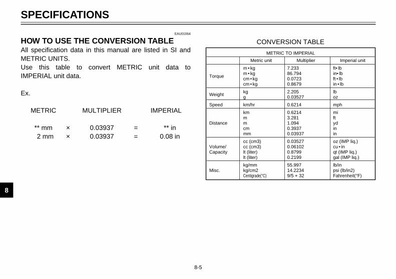
1
2
3
4
5
6
7
8
9
8-5
SPECIFICATIONS
EAU01064
HOW TO USE THE CONVERSION TABLEAll specification data in this manual are listed in SI andMETRIC UNITS.Use this table to convert METRIC unit data to IMPERIAL unit data.
Ex.
METRIC MULTIPLIER IMPERIAL
** mm × 0.03937 = ** in2 mm × 0.03937 = 0.08 in
METRIC TO IMPERIAL
Metric unit Multiplier Imperial unit
m • kg 7.233 ft• lb
Torquem • kg 86.794 in• lbcm • kg 0.0723 ft • lbcm • kg 0.8679 in • lb
Weightkg 2.205 lbg 0.03527 oz
Speed km/hr 0.6214 mph
km 0.6214 mim 3.281 ft
Distance m 1.094 ydcm 0.3937 inmm 0.03937 in
cc (cm3) 0.03527 oz (IMP liq.)Volume/ cc (cm3) 0.06102 cu • inCapacity lt (liter) 0.8799 qt (IMP liq.)
lt (liter) 0.2199 gal (IMP liq.)
kg/mm 55.997 lb/inMisc. kg/cm2 14.2234 psi (lb/in2)
Centigrade(°C) 9/5 + 32 Fahrenheit(°F)
CONVERSION TABLE
5GM-9-E0 4/13/0 9:10 PM Page 88

CONSUMER INFORMATION
Identification number records .............................................................9-1Key identification number ...................................................................9-1Vehicle identification number..............................................................9-1Model label .........................................................................................9-2
9
5GM-9-E0 4/13/0 9:10 PM Page 89

1
1
EAU02944
Identification numberrecordsRecord the key identification number,vehicle identification number andmodel label information in the spacesprovided for assistance when order-ing spare parts from a Yamaha deal-er or for reference in case the vehicleis stolen.
1. KEY IDENTIFICATIONNUMBER:
2. VEHICLE IDENTIFICATIONNUMBER:
3. MODEL LABEL INFORMATION:
EAU01041
Key identification numberThe key identification number isstamped on the key tag.Record this number in the space pro-vided and use it for reference whenobtaining a new key.
EAU01044
Vehicle identificationnumberThe vehicle identification number isstamped into the frame.
NOTE:The vehicle identification number isused to identify your scooter and maybe used to register your scooter withthe licensing authority in your state.
1. Key identification number 1. Vehicle identification number
9-1
EAU01039
CONSUMER INFORMATION
1
2
3
4
5
6
7
8
9
16
5GM-9-E0 4/13/0 9:10 PM Page 90

9-2
CONSUMER INFORMATION
1
2
4
5
6
7
8
9
1
EAU01804
Model labelThe model label is affixed to theframe under the rider seat. (See page3-12 for rider seat removal and instal-lation procedures.) Record the information on this labelin the space provided. This informa-tion will be needed to order spareparts from your Yamaha dealer.
1. Model label
5GM-9-E0 4/13/0 9:10 PM Page 91

INDEX
EEngine break-in .......................................5-3Engine oil...............................................6-11Engine stop switch ..................................3-9
FFinal gear oil replacement .....................6-14Front brake lever .....................................3-9Front fork inspection..............................6-24Front turn signal light bulb
replacement ........................................6-30Fuel .......................................................3-11Fuel gauge ..............................................3-5Fuel tank cap.........................................3-10Fuse replacement..................................6-27
HHandlebar switches .................................3-6
Dimmer switch ......................................3-6Engine stop switch................................3-9Pass switch...........................................3-6Turn signal switch .................................3-7Horn switch ...........................................3-7Light switch ...........................................3-7Start switch ...........................................3-9
Headlight beam variation.........................3-8Headlight bulb replacement...................6-28High beam indicator light.........................3-2Horn switch..............................................3-7How to use the conversion table .............8-5
IIdentification number records ..................9-1
Indicator lights .........................................3-2Turn indicator lights ..............................3-2High beam indicator light ......................3-2Oil change indicator light ......................3-2
Inspecting the brake fluid level ..............6-22
KKey identification number ........................9-1
LLicense light bulb replacement..............6-32Light switch..............................................3-7
MMain switch / Steering lock......................3-1Model label ..............................................9-2
OOil change indicator light circuit
check ....................................................3-3Oil change indicator light .........................3-2
PPanel A....................................................6-6Panel B....................................................6-8Panel C....................................................6-8Panel removal and installation ................6-6Parking ....................................................5-4Pass switch .............................................3-6Periodic maintenance and
lubrication .............................................6-3Pre-operation check list ...........................4-1
AAcceleration.............................................5-2Air filter and V-belt case filter
cleaning ..............................................6-16Air flow louver........................................6-18Antitheft alarm (optional) .........................3-5
BBattery ...................................................6-26Battery cover removal ...........................6-26Brake fluid replacement.........................6-23Brake lever free play adjustment...........6-20Brake lever lubrication...........................6-23Braking ....................................................5-2
CCable inspection and lubrication ...........6-23Care.........................................................7-1Carrier (option) ......................................3-16Catalyzer ...............................................3-12Center and sidestand lubrication...........6-24Checking the front and rear brake
pads ....................................................6-21Coolant ..................................................6-15Coolant temperature gauge.....................3-5
DDescription ..............................................2-1Diagnosis device .....................................3-4Digital clock .............................................3-6Dimmer switch.........................................3-6
5GM-9-E0 4/13/0 9:10 PM Page 92

RRear brake lever....................................3-10Rear shock absorber adjustment ..........3-15Rear turn signal light bulb
replacement ........................................6-31Rider seat ..............................................3-12Rider seat adjustment ...........................3-13
SSidestand ..............................................3-16Sidestand switch operation check .........3-17Spark plug .............................................6-10Specifications ..........................................8-1Speedometer...........................................3-4Start switch..............................................3-9Starting a cold engine..............................5-1Starting off ...............................................5-2Steering inspection................................6-25Storage....................................................7-4Storage compartments ..........................3-14
TTail/brake light bulb replacement ..........6-30Tires ......................................................6-18Tool kit .....................................................6-1Troubleshooting.....................................6-33Troubleshooting chart............................6-34Turn indicator lights .................................3-2Turn signal switch....................................3-7
VVehicle identification number ..................9-1
WWheel bearings .....................................6-25Wheels ..................................................6-20
INDEX
5GM-9-E0 4/13/0 9:10 PM Page 93

5GM-9-E0 4/13/0 9:10 PM Page 94

5GM-9-E0 4/13/0 9:10 PM Page 95

PRINTED ON RECYCLED PAPER PRINTED IN JAPAN
99·10–1.6×1(E) !
YAMAHA MOTOR CO., LTD.
5GM-9-E0(Hyoushi) 4/13/0 9:16 PM Page 1 (1,1) (Magenta plate)