yn50 / yn50m - boardindeks · as the owner of the yn50 / yn50m, you are benefiting from yamaha’s...
TRANSCRIPT

5C2-F8199-E3
YN50 / YN50M
OWNER’S MANUAL
Read this manual carefully before operating this vehicle.
5C2-F8199-E3 7/9/10 18:10 Página 1

EAU46090
Read this manual carefully before operating this vehicle. This manual should stay with this vehicle if it issold.
5C2-F8199-E3 7/9/10 18:10 Página 2
EAU10113
Welcome to the Yamaha world of motorcycling!As the owner of the YN50 / YN50M, you are benefiting from Yamaha’s vast experience and newest technology regar-ding the design and manufacture of high-quality products, which have earned Yamaha a reputation for dependability.Please take the time to read this manual thoroughly, so as to enjoy all advantages of your YN50 / YN50M. The Owner’sManual does not only instruct you in how to operate, inspect and maintain your scooter, but also in how to safeguardyourself and others from trouble and injury.In addition, the many tips given in this manual will help keep your scooter in the best possible condition. If you haveany further questions, do not hesitate to contact your Yamaha dealer.The Yamaha team wishes you many safe and pleasant rides. So, remember to put safety first!Yamaha continually seeks advancements in product design and quality. Therefore, while this manual contains the mostcurrent product information available at the time of printing, there may be minor discrepancies between your scooterand this manual. If there is any question concerning this manual, please consult a Yamaha dealer.
EWA12411
Please read this manual carefully and completely before operating this scooter.
WARNING
INTRODUCTION
5C2-F8199-E3 7/9/10 18:10 Página 3
EAU10132
Particularly important information is distinguished in this manual by the following notations:
IMPORTANT MANUAL INFORMATION
This is the safety alert symbol. It is used to alert you to potential personal injuryhazards. Obey all safety messages that follow this symbol to avoid possible injuryor death.
A WARNING indicates a hazardous situation which, if not avoided, could result indeath or serious injury.
A NOTICE indicates special precautions that must be taken to avoid damage to thevehicle or other property.
A TIP provides key information to make procedures easier or clearer.TIP
NOTICE
WARNING
5C2-F8199-E3 7/9/10 18:10 Página 4

EAUS1172
IMPORTANT MANUAL INFORMATION
YN50 / YN50MOWNER’S MANUAL
©2010 by YAMAHA MOTOR ESPAÑA S.A.1st edition, July 2010All rights reserved.
Any reprinting or unauthorized use without the written permission of YAMAHA MOTOR ESPAÑA S.A.
is expressly prohibited.Printed in Spain.
5C2-F8199-E3 7/9/10 18:10 Página 5

SAFETY INFORMATION.....................1-1Further safe-riding points .................1-5
DESCRIPTION.....................................2-1Left view ...........................................2-1Right view .........................................2-2Controls and instruments .................2-3
INSTRUMENT AND CONTROLFUNCTIONS ........................................3-1
Main switch/steering lock.................3-1Indicator and warning lights .............3-2Multi-function display .......................3-3Handlebar switches ..........................3-5Front brake lever...............................3-6Rear brake lever................................3-6Fuel and 2-stroke engine oil tank
caps...............................................3-7Fuel ...................................................3-8Fuel tank breather/overflow
hose...............................................3-9Catalytic converter............................3-92-stroke engine oil ..........................3-10Kickstarter.......................................3-10Seat.................................................3-10Storage compartment.....................3-11Luggage hook.................................3-12
FOR YOUR SAFETY – PRE-OPERATION CHECKS ...............4-1
OPERATION AND IMPORTANT RIDING POINTS..................................5-1
Starting a cold engine ......................5-1Starting off ........................................5-1Acceleration and deceleration..........5-2Braking..............................................5-2Tips for reducing fuel
consumption..................................5-3Engine break-in.................................5-3Parking..............................................5-4
PERIODIC MAINTENANCE ANDADJUSTMENT ....................................6-1
Periodic maintenance chart for theemission control system ...............6-2
General maintenance and lubrication chart ............................6-3
Removing and installing the cowling and panel .........................6-6
Checking the spark plug ..................6-7Final transmission oil ........................6-8Air filter element................................6-9Adjusting the carburetor .................6-10Checking the throttle grip
free play.......................................6-10Tires ................................................6-10Cast wheels ....................................6-12Checking the front brake lever
free play.......................................6-12Adjusting the rear brake lever
free play.......................................6-13
Checking the front brake pads and rear brake shoes ..................6-13
Checking the brake fluid level ........6-14Changing the brake fluid ................6-15Checking and lubricating the
cables ..........................................6-15Checking and lubricating the
throttle grip and cable .................6-16Adjusting the Autolube pump.........6-16Lubricating the front and rear
brake levers .................................6-16Checking and lubricating the
centerstand .................................6-17Checking the front fork...................6-17Checking the steering.....................6-18Checking the wheel bearings .........6-18Battery ............................................6-19Replacing the fuse..........................6-20Replacing the headlight bulb..........6-21Replacing a front turn signal light
bulb .............................................6-22Replacing a turn signal light bulb
or the tail/brake light bulb ...........6-23Replacing the license plate light
bulb (Depens on models) ............6-24Replacing the auxiliary light bulb
(Depens on models) ....................6-24Troubleshooting ..............................6-25Troubleshooting chart .....................6-26
TABLE OF CONTENTS
5C2-F8199-E3 7/9/10 18:10 Página 6
SCOOTER CARE AND STORAGE.....7-1Matte color caution...........................7-1Care ..................................................7-1Storage .............................................7-3
SPECIFICATIONS ...............................8-1
CONSUMER INFORMATION .............9-1Identification numbers ......................9-1
TABLE OF CONTENTS
5C2-F8199-E3 7/9/10 18:10 Página 7

EAUT1016
Be a Responsible OwnerAs the vehicle’s owner, you are res-ponsible for the safe and proper ope-ration of your scooter.Scooters are single-track vehicles.Their safe use and operation aredependent upon the use of properriding techniques as well as theexpertise of the operator. Every ope-rator should know the following requi-rements before riding this scooter.He or she should:
� Obtain thorough instructionsfrom a competent source on allaspects of scooter operation.
� Observe the warnings and main-tenance requirements in thisOwner’s Manual.
� Obtain qualified training in safeand proper riding techniques.
� Obtain professional technicalservice as indicated in thisOwner’s Manual and/or whenmade necessary by mechanicalconditions.
Safe RidingPerform the pre-operation checkseach time you use the vehicle tomake sure it is in safe operating con-dition. Failure to inspect or maintainthe vehicle properly increases thepossibility of an accident or equip-ment damage. See page 4-1 for a listof pre-operation checks.
� This scooter is designed to carrythe operator and a passenger.
TIPAlthough this scooter is designed tocarry a passenger, always complywith the local regulations.
� The failure of motorists to detectand recognize scooters in trafficis the predominating cause ofautomobile/scooter accidents.Many accidents have been cau-sed by an automobile driver whodid not see the scooter. Makingyourself conspicuous appears tobe very effective in reducing thechance of this type of accident.Therefore:• Wear a brightly colored jacket.
• Use extra caution when youare approaching and passingthrough intersections, sinceintersections are the mostlikely places for scooter acci-dents to occur.
• Ride where other motorists cansee you. Avoid riding in anot-her motorist’s blind spot.
� Many accidents involve inexpe-rienced operators. In fact, manyoperators who have been invol-ved in accidents do not evenhave a current driver’s license.• Make sure that you are quali-
fied and that you only lend yourscooter to other qualified ope-rators.
• Know your skills and limits.Staying within your limits mayhelp you to avoid an accident.
• We recommend that you prac-tice riding your scooter wherethere is no traffic until you havebecome thoroughly familiarwith the scooter and all of itscontrols.
� Many accidents have been cau-sed by error of the scooter ope-
1
SAFETY INFORMATION
1-1
5C2-F8199-E3 7/9/10 18:10 Página 8
rator. A typical error made by theoperator is veering wide on a turndue to excessive speed or under-cornering (insufficient lean anglefor the speed).• Always obey the speed limit
and never travel faster thanwarranted by road and trafficconditions.
• Always signal before turning orchanging lanes. Make sure thatother motorists can see you.
� The posture of the operator andpassenger is important for propercontrol.• The operator should keep both
hands on the handlebar andboth feet on the operator foo-trests during operation tomaintain control of the scooter.
• The passenger should alwayshold onto the operator, the seatstrap or grab bar, if equipped,with both hands and keep bothfeet on the passenger foo-trests. Never carry a passengerunless he or she can firmly pla-ce both feet on the passengerfootrests.
� Never ride under the influence ofalcohol or other drugs.
� This scooter is designed for on-road use only. It is not suitable foroff-road use.
Protective apparelThe majority of fatalities from scooteraccidents are the result of head inju-ries. The use of a safety helmet is thesingle most critical factor in the pre-vention or reduction of head injuries.
� Always wear an approved hel-met.
� Wear a face shield or goggles.Wind in your unprotected eyescould contribute to an impair-ment of vision that could delayseeing a hazard.
� The use of a jacket, substantialshoes, trousers, gloves, etc., iseffective in preventing or redu-cing abrasions or lacerations.
� Never wear loose-fitting clothes,otherwise they could catch onthe control levers or wheels andcause injury or an accident.
� Always wear protective clothingthat covers your legs, ankles, and
feet. The engine or exhaust sys-tem become very hot during orafter operation and can causeburns.
� A passenger should also observethe above precautions.
Avoid Carbon Monoxide PoisoningAll engine exhaust contains carbonmonoxide, a deadly gas. Breathingcarbon monoxide can cause heada-ches, dizziness, drowsiness, nausea,confusion, and eventually death.Carbon Monoxide is a colorless,odorless, tasteless gas which may bepresent even if you do not see orsmell any engine exhaust. Deadlylevels of carbon monoxide can collectrapidly and you can quickly be over-come and unable to save yourself.Also, deadly levels of carbon monoxi-de can linger for hours or days inenclosed or poorly ventilated areas. Ifyou experience any symptoms of car-bon monoxide poisoning, leave thearea immediately, get fresh air, andSEEK MEDICAL TREATMENT.
� Do not run engine indoors. Evenif you try to ventilate engine
1
SAFETY INFORMATION
1-2
5C2-F8199-E3 7/9/10 18:10 Página 9
exhaust with fans or open win-dows and doors, carbon monoxi-de can rapidly reach dangerouslevels.
� Do not run engine in poorly venti-lated or partially enclosed areassuch as barns, garages, or car-ports.
� Do not run engine outdoors whe-re engine exhaust can be drawninto a building through openingssuch as windows and doors.
LoadingAdding accessories or cargo to yourscooter can adversely affect stabilityand handling if the weight distributionof the scooter is changed. To avoidthe possibility of an accident, useextreme caution when adding cargoor accessories to your scooter. Useextra care when riding a scooter thathas added cargo or accessories.Here, along with the informationabout accessories below, are somegeneral guidelines to follow if loadingcargo to your scooter:The total weight of the operator, pas-senger, accessories and cargo must
not exceed the maximum load limit.Operation of an overloaded vehiclecould cause an accident.
When loading within this weight limit,keep the following in mind:
� Cargo and accessory weightshould be kept as low and closeto the scooter as possible. Secu-rely pack your heaviest items asclose to the center of the vehicleas possible and make sure to dis-tribute the weight as evenly aspossible on both sides of thescooter to minimize imbalance orinstability.
� Shifting weights can create asudden imbalance. Make surethat accessories and cargo aresecurely attached to the scooterbefore riding. Check accessorymounts and cargo restraints fre-quently.• Properly adjust the suspension
for your load (suspension-
adjustable models only), andcheck the condition and pres-sure of your tires.
• Never attach any large orheavy items to the handlebar,front fork, or front fender. Suchitems can create unstablehandling or a slow steering res-ponse.
� This vehicle is not designed topull a trailer or to be attachedto a sidecar.
Genuine Yamaha AccessoriesChoosing accessories for your vehicleis an important decision. GenuineYamaha accessories, which are avai-lable only from a Yamaha dealer, havebeen designed, tested, and approvedby Yamaha for use on your vehicle.Many companies with no connectionto Yamaha manufacture parts andaccessories or offer other modifica-tions for Yamaha vehicles. Yamaha isnot in a position to test the productsthat these aftermarket companiesproduce. Therefore, Yamaha can neit-her endorse nor recommend the useof accessories not sold by Yamaha or
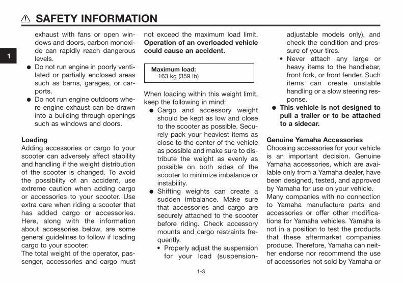
Maximum load:163 kg (359 lb)
1
SAFETY INFORMATION
1-3
5C2-F8199-E3 7/9/10 18:10 Página 10

modifications not specifically recom-mended by Yamaha, even if sold andinstalled by a Yamaha dealer.
Aftermarket Parts, Accessories,and ModificationsWhile you may find aftermarket pro-ducts similar in design and quality togenuine Yamaha accessories, recog-nize that some aftermarket accesso-ries or modifications are not suitablebecause of potential safety hazards toyou or others. Installing aftermarketproducts or having other modifica-tions performed to your vehicle thatchange any of the vehicle’s design oroperation characteristics can put youand others at greater risk of seriousinjury or death. You are responsiblefor injuries related to changes in thevehicle.Keep the following guidelines in mind,as well as those provided under “Loa-ding” when mounting accessories.
� Never install accessories or carrycargo that would impair the per-formance of your scooter. Care-fully inspect the accessory befo-re using it to make sure that it
does not in any way reduceground clearance or corneringclearance, limit suspension tra-vel, steering travel or control ope-ration, or obscure lights or reflec-tors.• Accessories fitted to the hand-
lebar or the front fork area cancreate instability due to impro-per weight distribution oraerodynamic changes. Ifaccessories are added to thehandlebar or front fork area,they must be as lightweight aspossible and should be kept toa minimum.
• Bulky or large accessories mayseriously affect the stability ofthe scooter due to aerodyna-mic effects. Wind may attemptto lift the scooter, or the scoo-ter may become unstable incross winds. These accesso-ries may also cause instabilitywhen passing or being passedby large vehicles.
• Certain accessories can dis-place the operator from his orher normal riding position.
This improper position limitsthe freedom of movement ofthe operator and may limitcontrol ability, therefore, suchaccessories are not recom-mended.
� Use caution when adding electri-cal accessories. If electricalaccessories exceed the capacityof the scooter’s electrical system,an electric failure could result,which could cause a dangerousloss of lights or engine power.
Aftermarket Tires and RimsThe tires and rims that came with yourscooter were designed to match theperformance capabilities and to pro-vide the best combination of hand-ling, braking, and comfort. Other tires,rims, sizes, and combinations maynot be appropriate. Refer to page 6-10 for tire specifications and moreinformation on replacing your tires.
Transporting the ScooterBe sure to observe following instruc-tions before transporting the scooterin another vehicle.
1
SAFETY INFORMATION
1-4
5C2-F8199-E3 7/9/10 18:10 Página 11

� Remove all loose items from thescooter.
� Point the front wheel straightahead on the trailer or in the truckbed, and choke it in a rail to pre-vent movement.
� Secure the scooter with tie-downs or suitable straps that areattached to solid parts of thescooter, such as the frame orupper front fork triple clamp (andnot, for example, to rubber-mounted handlebars or turn sig-nals, or parts that could break).Choose the location for thestraps carefully so the straps willnot rub against painted surfacesduring transport.
� The suspension should be com-pressed somewhat by the tie-downs, if possible, so that thescooter will not bounce excessi-vely during transport.
EAU10372
Further safe-riding points� Be sure to signal clearly when
making turns.� Braking can be extremely difficult
on a wet road. Avoid hard bra-king, because the scooter couldslide. Apply the brakes slowlywhen stopping on a wet surface.
� Slow down as you approach acorner or turn. Once you havecompleted a turn, accelerateslowly.
� Be careful when passing parkedcars. A driver might not see youand open a door in your path.
� Railroad crossings, streetcarrails, iron plates on road cons-truction sites, and manholecovers become extremely slip-pery when wet. Slow down andcross them with caution. Keepthe scooter upright, otherwise itcould slide out from under you.
� The brake pads could get wetwhen you wash the scooter. Afterwashing the scooter, check thebrakes before riding.
� Always wear a helmet, gloves,trousers (tapered around the cuffand ankle so they do not flap),and a bright colored jacket.
� Do not carry too much luggageon the scooter. An overloadedscooter is unstable. Use a strongcord to secure any luggage to thecarrier (if equipped). A loose loadwill affect the stability of the sco-oter and could divert your atten-tion from the road. (See page 1-1).
1
SAFETY INFORMATION
1-5
5C2-F8199-E3 7/9/10 18:10 Página 12

EAU10410
Left view
DESCRIPTION
2-1
2
1. Storage compartment (page 3-11)2. Shock absorber assembly3. Final transmission oil filler cap (page 6-8)4. Brake lever free play adjusting nut (page 6-13)5. Final transmission oil drain bolt (page 6-8)6. Kickstarter (page 3-10)7. Air filter element (page 6-9)8. Front brake pads (page 6-13)
5C2-F8199-E3 7/9/10 18:10 Página 1
EAU10420
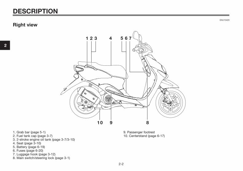
Right view
DESCRIPTION
2-2
2
1. Grab bar (page 5-1)2. Fuel tank cap (page 3-7)3. 2-stroke engine oil tank (page 3-7/3-10)4. Seat (page 3-10)5. Battery (page 6-19)6. Fuses (page 6-20)7. Luggage hook (page 3-12)8. Main switch/steering lock (page 3-1)
9. Passenger footrest10. Centerstand (page 6-17)
5C2-F8199-E3 7/9/10 18:10 Página 2
EAU10430
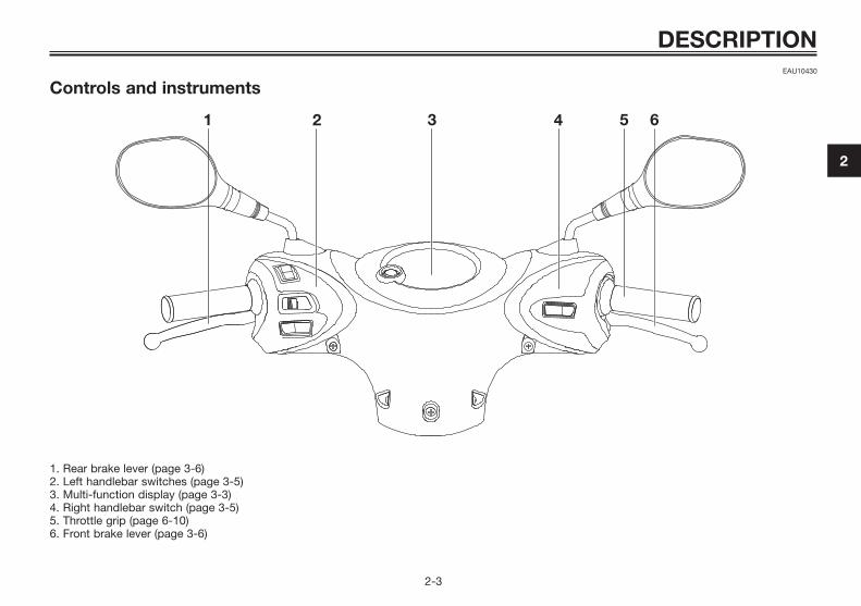
Controls and instruments
DESCRIPTION
2-3
2
1. Rear brake lever (page 3-6)2. Left handlebar switches (page 3-5)3. Multi-function display (page 3-3)4. Right handlebar switch (page 3-5)5. Throttle grip (page 6-10)6. Front brake lever (page 3-6)
5C2-F8199-E3 7/9/10 18:10 Página 3

EAU10460
Main switch/steering lock
The main switch/steering lock con-trols the ignition and lighting systems,and is used to lock the steering. Thevarious positions are describedbelow.
EAUS1381
ON “ ”All electrical circuits are supplied withpower, the meter lighting comes on,and the engine can be started. Thekey cannot be removed.
TIPThe headlight and taillight come onautomatically when the engine is star-ted.
EAU47791
OFF “ ”All electrical systems are off. The keycan be removed.
EWA15350
Never turn the key to “ ” or “ ”while the vehicle is moving.Otherwise the electrical systemswill be switched off, which mayresult in loss of control or an acci-dent.
EAU10681
LOCK “ ”The steering is locked, and all electri-cal systems are off. The key can beremoved.
To lock the steering
1. Push2. Turn
1. Turn the handlebars all the way tothe left.
2. Push the key in from the “ ”position, and then turn it to “ ”while still pushing it.
3. Remove the key.
To unlock the steering
1. Push2. Turn
Push the key in, and then turn it to“ ” while still pushing it.
WARNING
INSTRUMENT AND CONTROL FUNCTIONS
3-1
3
5C2-F8199-E3 7/9/10 18:10 Página 4

EAU11004
Indicator and warning lights
1. 2-stroke engine oil level warning light “ ”2. High beam indicator light “ ”3. Turn signal indicator light “ ”4. Fuel level warning indicator “ ”
EAU11020
Turn signal indicator light “ ”This indicator light flashes when theturn signal switch is pushed to the leftor right.
EAU11080
High beam indicator light “ ”This indicator light comes on whenthe high beam of the headlight is swit-ched on.
EAUM1062
Oil level warning light “ ”This warning light comes on when thekey is in the “ ” position or if the oillevel in the 2-stroke engine oil tank islow during operation. If the warninglight comes on during operation, stopimmediately and fill the oil tank with2-stroke engine oil of either JASOgrade “FC” or ISO grades “EG-C” or“EG-D”. The warning light should gooff after the 2-stroke engine oil tankhas been refilled.
TIPIf the warning light does not come onwhen the key is in the “ ” positionor does not go off after the 2-strokeengine oil tank has been refilled, havea Yamaha dealer check the electricalcircuit.
ECA16291
Do not operate the vehicle until youknow that the engine oil level is suf-ficient.
EAU11352
Fuel level warning light “ ”This warning light comes on when thefuel level drops below approximately1.4 L (0.37 US gal, 0.31 Imp.gal).When this occurs, refuel as soon aspossible.The electrical circuit of the warninglight can be checked by turning thekey to “ ”. The warning light shouldcome on for a few seconds, and thengo off.If the warning light does not come oninitially when the key is turned to “ ”,or if the warning light remains on,have a Yamaha dealer check the elec-trical circuit.
NOTICE
INSTRUMENT AND CONTROL FUNCTIONS
3-2
3
5C2-F8199-E3 7/9/10 18:10 Página 5
EAUS1394
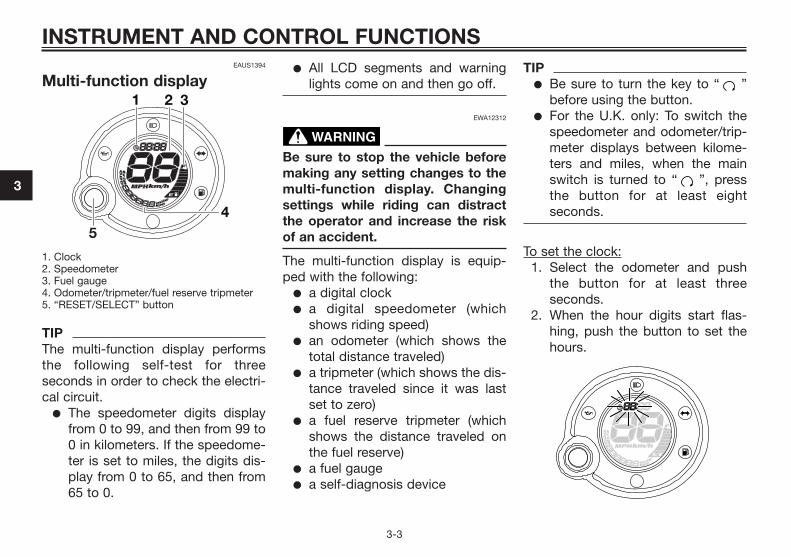
Multi-function display
1. Clock2. Speedometer 3. Fuel gauge4. Odometer/tripmeter/fuel reserve tripmeter5. “RESET/SELECT” button
TIPThe multi-function display performsthe following self-test for threeseconds in order to check the electri-cal circuit.
� The speedometer digits displayfrom 0 to 99, and then from 99 to0 in kilometers. If the speedome-ter is set to miles, the digits dis-play from 0 to 65, and then from65 to 0.
� All LCD segments and warninglights come on and then go off.
EWA12312
Be sure to stop the vehicle beforemaking any setting changes to themulti-function display. Changingsettings while riding can distractthe operator and increase the riskof an accident.
The multi-function display is equip-ped with the following:
� a digital clock� a digital speedometer (which
shows riding speed)� an odometer (which shows the
total distance traveled)� a tripmeter (which shows the dis-
tance traveled since it was lastset to zero)
� a fuel reserve tripmeter (whichshows the distance traveled onthe fuel reserve)
� a fuel gauge� a self-diagnosis device
TIP� Be sure to turn the key to “ ”
before using the button.� For the U.K. only: To switch the
speedometer and odometer/trip-meter displays between kilome-ters and miles, when the mainswitch is turned to “ ”, pressthe button for at least eightseconds.
To set the clock:1. Select the odometer and push
the button for at least threeseconds.
2. When the hour digits start flas-hing, push the button to set thehours.
WARNING
INSTRUMENT AND CONTROL FUNCTIONS
3-3
3
5C2-F8199-E3 7/9/10 18:10 Página 6

3. To change the minutes digits,push the button for at least threeseconds.
4. When the minutes digits startflashing, push the button to setthe minutes.
5. Push the button for at least threeseconds to start the clock.
TIPAfter setting the clock, be sure topush the button for at least threeseconds before turning the key to“ ”, otherwise the clock will not beset.
Odometer and tripmeter modesPushing the button switches the dis-play between the odometer mode“ODO” and the tripmeter “TRIP” inthe following order:ODO � TRIP � ODO
If the fuel level warning indicatorcomes on (see page 3-2), the odome-ter display will automatically changeto the fuel reserve tripmeter mode“TRIP F” and start counting the dis-tance traveled from that point. In thatcase, pushing the button switches thedisplay between the various tripmeterand odometer modes in the followingorder:TRIP F � ODO � TRIP � TRIP F
To reset a tripmeter, select it by pus-hing the button, and then push itagain for at least three seconds. If youdo not reset the fuel reserve tripmetermanually, it will reset itself automati-cally and the display will return to theprior mode after refueling and trave-ling 5 km (3 mi).
TIPThe display cannot be changed backto “TRIP F” after pushing the button.
Fuel gaugeThe fuel gauge indicates the amountof fuel in the fuel tank. The displaysegments of the fuel gauge disappeartowards “E” (Empty) as the fuel level
RESET/
SELECT
RESET/
SELECT
RESET/ SELECT
RESET/ SELECTRESET/SELECT
INSTRUMENT AND CONTROL FUNCTIONS
3-4
3
5C2-F8199-E3 7/9/10 18:10 Página 7
decreases. When only two segmentsare left near “E”, the fuel level warningindicator comes on. Refuel as soonas possible.
Self-diagnosis deviceThis model is equipped with a self-diagnosis device for the fuel electricalcircuit.If a problem is detected in the fuelelectrical circuit, all LCD segments ofthe fuel gauge and the fuel level war-ning indicator will flash. If this occurs,have a Yamaha dealer check the vehi-cle.
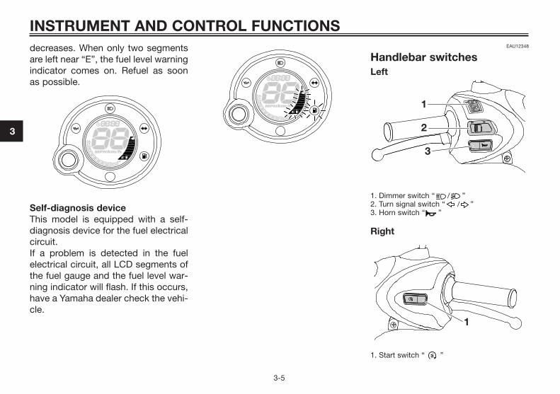
EAU12348
Handlebar switchesLeft
1. Dimmer switch “ / ”2. Turn signal switch “ / ”3. Horn switch “ ”
Right
1. Start switch “ ”
INSTRUMENT AND CONTROL FUNCTIONS
3-5
3
5C2-F8199-E3 7/9/10 18:10 Página 8

EAU12400
Dimmer switch “ / ”Set this switch to “ ” for the highbeam and to “ ” for the low beam.
EAU12460
Turn signal switch “ / ”To signal a right-hand turn, push thisswitch to “ ”. To signal a left-handturn, push this switch to “ ”. Whenreleased, the switch returns to thecenter position. To cancel the turnsignal lights, push the switch in after ithas returned to the center position.
EAU12500
Horn switch “ ”Press this switch to sound the horn.
EAUM1132
Start switch “ ”Push this switch while applying thefront or rear brake to crank the enginewith the starter. See page 5-1 for star-ting instructions prior to starting theengine.
EAU12900
Front brake lever
1. Front brake lever
The front brake lever is located on theright handlebar grip. To apply thefront brake, pull this lever toward thehandlebar grip.
EAU12950
Rear brake lever
1. Rear brake lever
The rear brake lever is located on theleft handlebar grip. To apply the rearbrake, pull this lever toward the hand-lebar grip.
INSTRUMENT AND CONTROL FUNCTIONS
3-6
3
5C2-F8199-E3 7/9/10 18:10 Página 9

EAU13202
Fuel and 2-stroke engine oiltank caps
1. 2-stroke engine oil tank cap 2. Fuel tank cap
The fuel tank cap and the 2-strokeengine oil tank cap are located underthe seat. (See page 3-10).
Fuel tank cap
1. Fuel tank cap
To remove the fuel tank cap, turn itcounterclockwise, and then pull it off.To install the fuel tank cap, turn itclockwise.
2-stroke engine oil tank cap
1. 2-stroke engine oil tank cap
To remove the 2-stroke engine oil tankcap, pull it off.To install the 2-stroke engine oil tankcap, push it into the oil tank opening.
EWA10141
Make sure that the fuel and 2-stro-ke engine oil tank caps are properlyinstalled before riding the scooter.Leaking fuel is a fire hazard.
WARNING
INSTRUMENT AND CONTROL FUNCTIONS
3-7
3
5C2-F8199-E3 7/9/10 18:10 Página 10
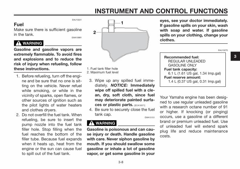
EAU13221
FuelMake sure there is sufficient gasolinein the tank.
EWA10881
Gasoline and gasoline vapors areextremely flammable. To avoid firesand explosions and to reduce therisk of injury when refueling, followthese instructions.
1. Before refueling, turn off the engi-ne and be sure that no one is sit-ting on the vehicle. Never refuelwhile smoking, or while in thevicinity of sparks, open flames, orother sources of ignition such asthe pilot lights of water heatersand clothes dryers.
2. Do not overfill the fuel tank. Whenrefueling, be sure to insert thepump nozzle into the fuel tankfiller hole. Stop filling when thefuel reaches the bottom of thefiller tube. Because fuel expandswhen it heats up, heat from theengine or the sun can cause fuelto spill out of the fuel tank.
1. Fuel tank filler hole2. Maximum fuel level
3. Wipe up any spilled fuel imme-diately. NOTICE: Immediatelywipe off spilled fuel with a cle-an, dry, soft cloth, since fuelmay deteriorate painted surfa-ces or plastic parts. [ECA10071]
4. Be sure to securely close the fueltank cap.
EWA15151
Gasoline is poisonous and can cau-se injury or death. Handle gasolinewith care. Never siphon gasoline bymouth. If you should swallow somegasoline or inhale a lot of gasolinevapor, or get some gasoline in your
eyes, see your doctor immediately.If gasoline spills on your skin, washwith soap and water. If gasolinespills on your clothing, change yourclothes.
EAU13270
Your Yamaha engine has been desig-ned to use regular unleaded gasolinewith a research octane number of 91or higher. If knocking (or pinging)occurs, use a gasoline of a differentbrand or premium unleaded fuel. Useof unleaded fuel will extend sparkplug life and reduce maintenancecosts.
Recommended fuel:REGULAR UNLEADEDGASOLINE ONLY
Fuel tank capacity:6.1 L (1.61 US gal, 1.34 Imp.gal)
Fuel reserve amount:1.4 L (0.37 US gal, 0.31 Imp.gal)
WARNING
WARNING
INSTRUMENT AND CONTROL FUNCTIONS
3-8
3
5C2-F8199-E3 7/9/10 18:10 Página 11
EAU39451
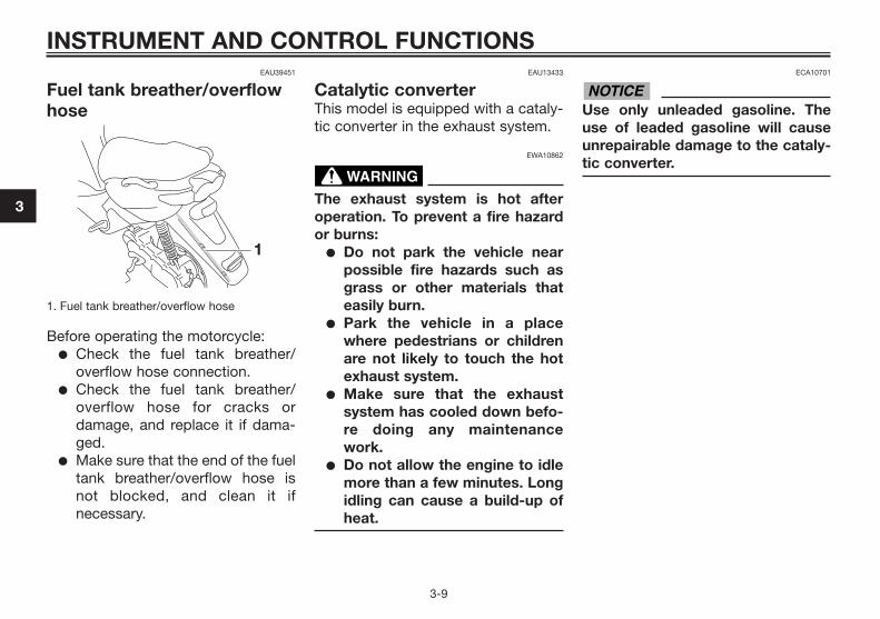
Fuel tank breather/overflowhose
1. Fuel tank breather/overflow hose
Before operating the motorcycle:� Check the fuel tank breather/
overflow hose connection.� Check the fuel tank breather/
overflow hose for cracks ordamage, and replace it if dama-ged.
� Make sure that the end of the fueltank breather/overflow hose isnot blocked, and clean it ifnecessary.
EAU13433
Catalytic converterThis model is equipped with a cataly-tic converter in the exhaust system.
EWA10862
The exhaust system is hot afteroperation. To prevent a fire hazardor burns:
� Do not park the vehicle nearpossible fire hazards such asgrass or other materials thateasily burn.
� Park the vehicle in a placewhere pedestrians or childrenare not likely to touch the hotexhaust system.
� Make sure that the exhaustsystem has cooled down befo-re doing any maintenancework.
� Do not allow the engine to idlemore than a few minutes. Longidling can cause a build-up ofheat.
ECA10701
Use only unleaded gasoline. Theuse of leaded gasoline will causeunrepairable damage to the cataly-tic converter.
NOTICE
WARNING
INSTRUMENT AND CONTROL FUNCTIONS
3-9
3
5C2-F8199-E3 7/9/10 18:10 Página 12

EAUM1150
2-stroke engine oilMake sure that there is sufficient oil inthe 2-stroke engine oil tank. Add therecommended 2-stroke engine oil ifnecessary.
TIPMake sure that the 2-stroke engine oiltank cap is properly installed.
EAUS1050
Kickstarter
1. Kickstarter lever
To start the engine, push the kickstar-ter down lightly with your foot until thegears engage, and then push it downsmoothly but forcefully.
EAU13932
Seat
To open the seat1. Place the scooter on the centers-
tand.2. Insert the key into the main
switch, and then turn it counter-clockwise to “OPEN”.
1. Open
TIPDo not push inward when turning thekey.
3. Fold the seat up.
Recommended oil:2-stroke engine oil (JASO grade“FC”, or ISO grades ”EG-C” or“EG-D”)
Oil quantity:1.50 L (1.59 US qt, 1.32 Imp.qt)
INSTRUMENT AND CONTROL FUNCTIONS
3-10
3
5C2-F8199-E3 7/9/10 18:10 Página 13

1. Seat open position
To close the seat1. Fold the seat down, and then
push it down to lock it in place.2. Remove the key from the main
switch if the scooter will be leftunattended.
TIPMake sure that the seat is properlysecured before riding.
EAUM1191
Storage compartment
1. Storage compartment
There is a storage compartmentunder the seat. (See page 3-10).
EWA10961
� Do not exceed the load limit of5 kg (11.0 lb) for the storagecompartment.
� Do not exceed the maximumload of 163 kg (359 lb) for thevehicle.
ECA10080
Keep the following points in mindwhen using the storage compart-ment.
� Since the storage compart-ment accumulates heat whenexposed to the sun, do not sto-re anything susceptible to heatinside it.
� To avoid humidity from sprea-ding through the storage com-partment, wrap wet articles ina plastic bag before storingthem in the compartment.
� Since the storage compart-ment may get wet while thescooter is being washed, wrapany articles stored in the com-partment in a plastic bag.
� Do not keep anything valuableor breakable in the storagecompartment.
To store a helmet in the storage com-partment, place the helmet with thefront facing backward.
NOTICE
WARNING
INSTRUMENT AND CONTROL FUNCTIONS
3-11
3
5C2-F8199-E3 7/9/10 18:10 Página 14
TIP� Some helmets cannot be stored
in the storage compartmentbecause of their size or shape.
� Do not leave your scooter unat-tended with the seat open.
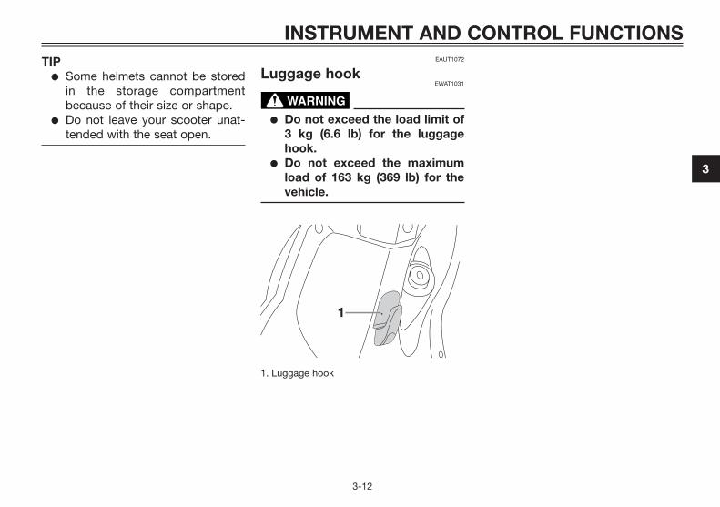
EAUT1072
Luggage hookEWAT1031
� Do not exceed the load limit of3 kg (6.6 lb) for the luggagehook.
� Do not exceed the maximumload of 163 kg (369 lb) for thevehicle.
1. Luggage hook
WARNING
INSTRUMENT AND CONTROL FUNCTIONS
3-12
3
5C2-F8199-E3 7/9/10 18:10 Página 15

EAU15596
Inspect your vehicle each time you use it to make sure the vehicle is in safe operating condition. Always followthe inspection and maintenance procedures and schedules described in the Owner’s Manual.
EWA11151
Failure to inspect or maintain the vehicle properly increases the possibility of an accident or equipment dama-ge. Do not operate the vehicle if you find any problem. If a problem cannot be corrected by the procedures pro-vided in this manual, have the vehicle inspected by a Yamaha dealer.
Before using this vehicle, check the following points:
WARNING
FOR YOUR SAFETY – PRE-OPERATION CHECKS
4-1
4
ITEM CHECKS PAGE• Check fuel level in fuel tank.
Fuel • Refuel if necessary. 3-8• Check fuel line for leakage.• Check oil level in oil tank.
2-stroke engine oil • If necessary, add recommended oil to specified level. 3-10• Check vehicle for oil leakage.
Final transmission oil • Check vehicle for oil leakage. 6-8• Check operation.• If soft or spongy, have Yamaha dealer bleed hydraulic system.• Check brake pads for wear.
Front brake • Replace if necessary. 6-13, 6-14• Check fluid level in reservoir.• If necessary, add recommended brake fluid to specified level.• Check hydraulic system for leakage.• Check operation.
Rear brake• Lubricate cable if necessary.• Check lever free play.
6-13
• Adjust if necessary.
5C2-F8199-E3 7/9/10 18:10 Página 16

ITEM CHECKS PAGE• Make sure that operation is smooth.
Throttle grip• Check throttle grip free play.• If necessary, have Yamaha dealer adjust throttle grip free play and lubricate
6-10, 6-16
cable and grip housing.• Check for damage.
Wheels and tires• Check tire condition and tread depth.
6-10, 6-12• Check air pressure.• Correct if necessary.
Brake levers• Make sure that operation is smooth.• Lubricate lever pivoting points if necessary.
6-16
Centerstand• Make sure that operation is smooth.• Lubricate pivot if necessary.
6-17
Chassis fasteners• Make sure that all nuts, bolts and screws are properly tightened.• Tighten if necessary.
—
Instruments, lights, • Check operation.signals and switches • Correct if necessary.
—
Battery• Check fluid level.• Fill with distilled water if necessary.
6-19
FOR YOUR SAFETY – PRE-OPERATION CHECKS
4-2
4
5C2-F8199-E3 7/9/10 18:10 Página 17

EAU15951
Read the Owner’s Manual carefully tobecome familiar with all controls. Ifthere is a control or function you donot understand, ask your Yamahadealer.
EWA10271
Failure to familiarize yourself withthe controls can lead to loss ofcontrol, which could cause an acci-dent or injury.
EAUT1101
Starting a cold engineECA10250
See page 5-3 for engine break-ininstructions prior to operating thevehicle for the first time.
1. Turn the key to “ ”.2. Close the throttle grip comple-
tely.3. Start the engine by pushing the
start switch or by kicking thekickstarter, while applying thefront or rear brake. NOTICE: Formaximum engine life, neveraccelerate hard when the engi-ne is cold! [ECA11041]
3. If the engine fails to start by pus-hing the start switch, release theswitch, wait a few seconds, andthen try again. Each startingattempt should be as short aspossible to preserve the battery.Do not crank the engine morethan 5 seconds on any oneattempt. If the engine does notstart with the starter motor, tryusing the kickstarter.
EAU16770
Starting off
TIPBefore starting off, allow the engine towarm up.
1. While pulling the rear brake leverwith your left hand and holdingthe carrier with your right hand,push the scooter off the centers-tand.
1. Grab bar 2. Rear brake lever
2. Sit astride the seat, and thenadjust the rear view mirrors.
3. Switch the turn signal on.
NOTICE
WARNING
OPERATION AND IMPORTANT RIDING POINTS
5-1
5
5C2-F8199-E3 7/9/10 18:10 Página 18

4. Check for oncoming traffic, andthen slowly turn the throttle grip(on the right) in order to take off.
5. Switch the turn signal off.
EAU16780
Acceleration anddeceleration
The speed can be adjusted by ope-ning and closing the throttle. To incre-ase the speed, turn the throttle grip indirection (a). To reduce the speed,turn the throttle grip in direction (b).
EAU16793
BrakingEWA10300
� Avoid braking hard or suddenly(especially when leaning overto one side), otherwise the sco-oter may skid or overturn.
� Railroad crossings, streetcarrails, iron plates on road cons-truction sites, and manholecovers become extremely slip-pery when wet. Therefore, slowdown when approaching suchareas and cross them with cau-tion.
� Keep in mind that braking on awet road is much more difficult.
� Ride slowly down a hill, as bra-king downhill can be very diffi-cult.
1. Close the throttle completely.2. Apply both front and rear brakes
simultaneously while graduallyincreasing the pressure.
WARNING
(b)
(a)
ZAUM0199
OPERATION AND IMPORTANT RIDING POINTS
5-2
5
5C2-F8199-E3 7/9/10 18:10 Página 19

Front
Rear
EAU16820
Tips for reducing fuelconsumptionFuel consumption depends largely onyour riding style. Consider the follo-wing tips to reduce fuel consumption:
� Avoid high engine speeds duringacceleration.
� Avoid high engine speeds with noload on the engine.
� Turn the engine off instead of let-ting it idle for an extended lengthof time (e.g., in traffic jams, attraffic lights or at railroad cros-sings).
EAU16830
Engine break-inThere is never a more importantperiod in the life of your engine thanthe period between 0 and 1000 km(600 mi). For this reason, you shouldread the following material carefully.Since the engine is brand new, do notput an excessive load on it for the first1000 km (600 mi). The various parts inthe engine wear and polish themsel-ves to the correct operating clearan-ces. During this period, prolongedfull-throttle operation or any conditionthat might result in engine overhea-ting must be avoided.
EAUM2091
0–150 km (0–90 mi)� Avoid prolonged operation above
1/3 throttle. Vary the speed of thescooter from time to time. Do notoperate it at one set throttle posi-tion.
150–500 km (90–300 mi)� Avoid prolonged operation above
1/2 throttle.
OPERATION AND IMPORTANT RIDING POINTS
5-3
5
5C2-F8199-E3 7/9/10 18:10 Página 20

500–1000 km (300–600 mi)� Avoid cruising speeds in excess
of 3/4 throttle.
1000 km (600 mi) and beyond� Avoid prolonged full throttle ope-
ration. Vary speeds occasionally.NOTICE: After 1000 km (600 mi)of operation, the final trans-mission oil must be chan-ged. [ECAM1071]
ECA10270
If any engine trouble should occurduring the engine break-in period,immediately have a Yamaha dealercheck the vehicle.
EAU17213
ParkingWhen parking, stop the engine, andthen remove the key from the mainswitch.
EWA10311
� Since the engine and exhaustsystem can become very hot,park in a place where pedes-trians or children are not likelyto touch them and be burned.
� Do not park on a slope or onsoft ground, otherwise thevehicle may overturn, increa-sing the risk of a fuel leak andfire.
� Do not park near grass or otherflammable materials whichmight catch fire.
WARNING
NOTICE
OPERATION AND IMPORTANT RIDING POINTS
5-4
5
5C2-F8199-E3 7/9/10 18:10 Página 21
EAU17241
Periodic inspection, adjustment, andlubrication will keep your vehicle inthe safest and most efficient condi-tion possible. Safety is an obligationof the vehicle owner/operator. Themost important points of vehicle ins-pection, adjustment, and lubricationare explained on the following pages.The intervals given in the periodicmaintenance and lubrication chartshould be simply considered as ageneral guide under normal ridingconditions. However, depending onthe weather, terrain, geographicallocation, and individual use, the main-tenance intervals may need to beshortened.
EWA10321
Failure to properly maintain thevehicle or performing maintenanceactivities incorrectly may increaseyour risk of injury or death duringservice or while using the vehicle. Ifyou are not familiar with vehicleservice, have a Yamaha dealer per-form service.
EWA15121
Turn off the engine when perfor-ming maintenance unless otherwi-se specified.
� A running engine has movingparts that can catch on bodyparts or clothing and electricalparts that can cause shocks orfires.
� Running the engine while servi-cing can lead to eye injury,burns, fire, or carbon monoxidepoisoning – possibly leading todeath. See page 1-1 for moreinformation about carbonmonoxide.
WARNING
WARNING
PERIODIC MAINTENANCE AND ADJUSTMENT
6-1
6
5C2-F8199-E3 7/9/10 18:10 Página 22

EAU46871
TIP� The annual checks must be performed every year, except if a kilometer-based maintenance, or for the UK,
a mileage-based maintenance, is performed instead.� From 30000 km (17500 mi), repeat the maintenance intervals starting from 6000 km (3500 mi).� Items marked with an asterisk should be performed by a Yamaha dealer as they require special tools, data and
technical skills.
EAU46920
Periodic maintenance chart for the emission control system
PERIODIC MAINTENANCE AND ADJUSTMENT
6-2
6
ODOMETER READINGCHECK OR ANNUAL
NO. ITEM MAINTENANCE JOB 1000 km 6000 km 12000 km 18000 km 24000 km CHECK(600 mi) (3500 mi) (7000 mi) (10500 mi) (14000 mi)
1 * Fuel line• Check fuel and vacuum hoses
for cracks or damage.√ √ √ √ √
2 Spark plug • Replace. √ √ √ √ √
3 * Carburetor • Adjust engine idling speed. √ √ √ √ √ √
• Check the air cut-off valve,
4 *Air induction reed valve, and hose for damage.
√ √ √ √ √system • Replace any damaged parts if necessary.
5C2-F8199-E3 7/9/10 18:10 Página 23
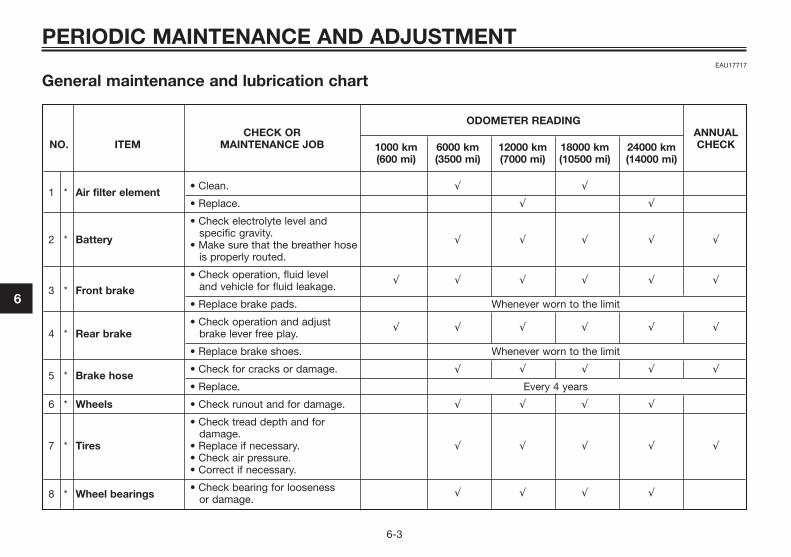
EAU17717
General maintenance and lubrication chart
PERIODIC MAINTENANCE AND ADJUSTMENT
6-3
6
ODOMETER READINGCHECK OR ANNUAL
NO. ITEM MAINTENANCE JOB 1000 km 6000 km 12000 km 18000 km 24000 km CHECK(600 mi) (3500 mi) (7000 mi) (10500 mi) (14000 mi)
1 * Air filter element• Clean. √ √
• Replace. √ √
• Check electrolyte level and
2 * Batteryspecific gravity.
à à à à å Make sure that the breather hose is properly routed.
• Check operation, fluid level
3 * Front brake and vehicle for fluid leakage.√ √ √ √ √ √
• Replace brake pads. Whenever worn to the limit
• Check operation and adjust 4 * Rear brake brake lever free play.
√ √ √ √ √ √
• Replace brake shoes. Whenever worn to the limit
5 * Brake hose• Check for cracks or damage. √ √ √ √ √
• Replace. Every 4 years
6 * Wheels • Check runout and for damage. √ √ √ √
• Check tread depth and for damage.
7 * Tires • Replace if necessary. √ √ √ √ √• Check air pressure.• Correct if necessary.
8 * Wheel bearings• Check bearing for looseness
or damage.√ √ √ √
5C2-F8199-E3 7/9/10 18:10 Página 24
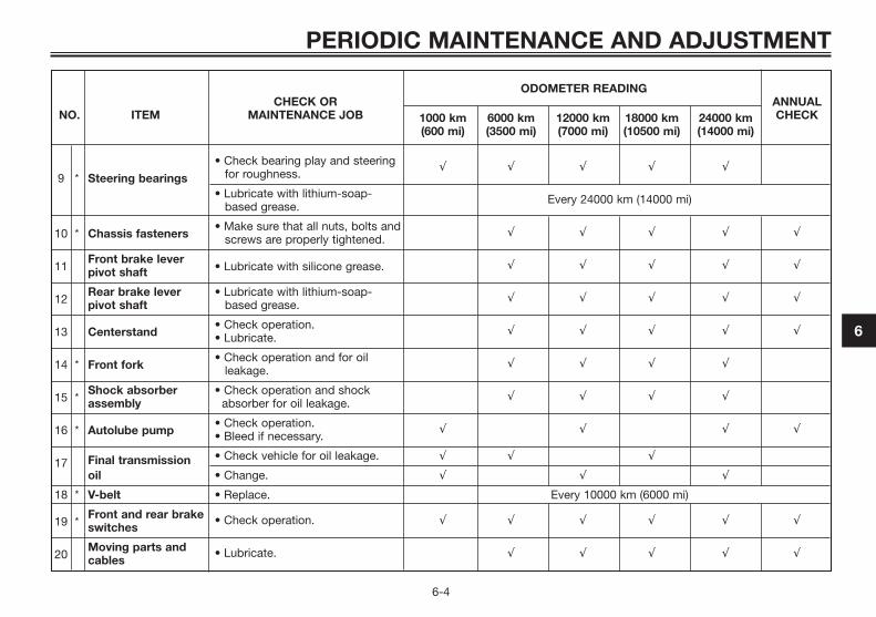
ODOMETER READINGCHECK OR ANNUAL
NO. ITEM MAINTENANCE JOB 1000 km 6000 km 12000 km 18000 km 24000 km CHECK(600 mi) (3500 mi) (7000 mi) (10500 mi) (14000 mi)
• Check bearing play and steering
9 * Steering bearings for roughness.√ √ √ √ √
• Lubricate with lithium-soap- based grease.
Every 24000 km (14000 mi)
10 * Chassis fasteners• Make sure that all nuts, bolts and
screws are properly tightened.√ √ √ √ √
11Front brake lever
• Lubricate with silicone grease.pivot shaft√ √ √ √ √
12Rear brake lever • Lubricate with lithium-soap-pivot shaft based grease.
√ √ √ √ √
13 Centerstand• Check operation.• Lubricate.
√ √ √ √ √
14 * Front fork• Check operation and for oil
leakage.√ √ √ √
15 *Shock absorber • Check operation and shock assembly absorber for oil leakage.
√ √ √ √
16 * Autolube pump• Check operation.• Bleed if necessary.
√ √ √ √
17 Final transmission • Check vehicle for oil leakage. √ √ √
oil • Change. √ √ √
18 * V-belt • Replace. Every 10000 km (6000 mi)
19 *Front and rear brake switches
• Check operation. √ √ √ √ √ √
20Moving parts and cables
• Lubricate. √ √ √ √ √
PERIODIC MAINTENANCE AND ADJUSTMENT
6-4
6
5C2-F8199-E3 7/9/10 18:10 Página 25

ODOMETER READINGCHECK OR ANNUAL
NO. ITEM MAINTENANCE JOB 1000 km 6000 km 12000 km 18000 km 24000 km CHECK(600 mi) (3500 mi) (7000 mi) (10500 mi) (14000 mi)
• Check operation and free play.Throttle grip • Adjust the throttle cable free
21 * housing play if necessary. √ √ √ √ √and cable • Lubricate the throttle grip
housing and cable.
22 *Lights, signals and • Check operation.switches • Adjust headlight beam.
√ √ √ √ √ √
PERIODIC MAINTENANCE AND ADJUSTMENT
6-5
6
EAUM2070
TIP� The air filter needs more frequent service if you are riding in unusually wet or dusty areas.� Hydraulic brake service
• Regularly check and, if necessary, correct the brake fluid level.• Every two years change the brake fluid.• Replace the brake hoses every four years and if cracked or damaged.
5C2-F8199-E3 7/9/10 18:10 Página 26
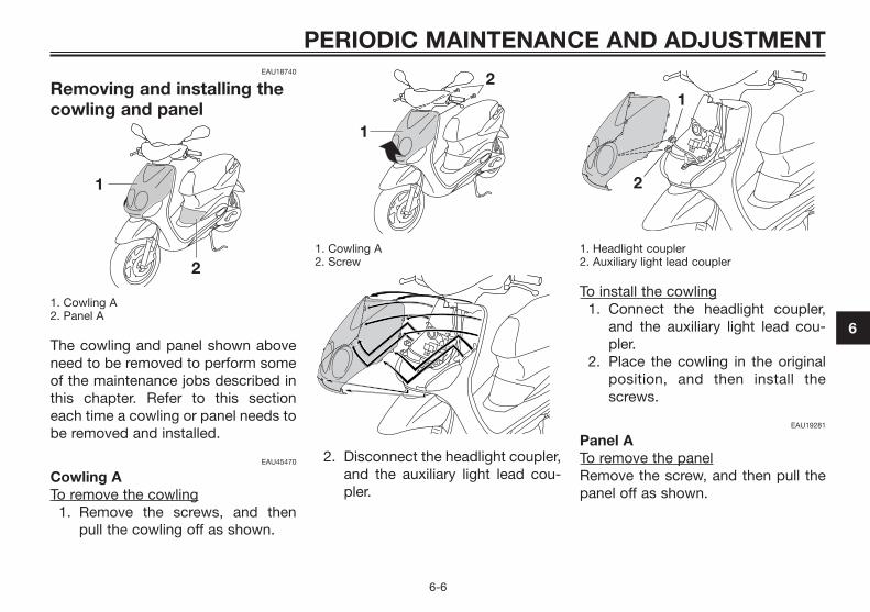
EAU18740
Removing and installing thecowling and panel
1. Cowling A2. Panel A
The cowling and panel shown aboveneed to be removed to perform someof the maintenance jobs described inthis chapter. Refer to this sectioneach time a cowling or panel needs tobe removed and installed.
EAU45470
Cowling ATo remove the cowling
1. Remove the screws, and thenpull the cowling off as shown.
1. Cowling A2. Screw
2. Disconnect the headlight coupler,and the auxiliary light lead cou-pler.
1. Headlight coupler2. Auxiliary light lead coupler
To install the cowling1. Connect the headlight coupler,
and the auxiliary light lead cou-pler.
2. Place the cowling in the originalposition, and then install thescrews.
EAU19281
Panel ATo remove the panelRemove the screw, and then pull thepanel off as shown.
PERIODIC MAINTENANCE AND ADJUSTMENT
6-6
6
5C2-F8199-E3 7/9/10 18:10 Página 27

1. Screw
1. Panel A
To install the panelPlace the panel in the original posi-tion, and then install the screw.
EAUS1760
Checking the spark plugThe spark plug is an important enginecomponent, which is easy to check.Since heat and deposits will causeany spark plug to slowly erode, thespark plug should be removed andchecked in accordance with theperiodic maintenance and lubricationchart. In addition, the condition of thespark plug can reveal the condition ofthe engine.
To remove the spark plug1. Remove panel A. (See page 6-6). 2. Remove the spark plug cap.
1. Spark plug cap
3. Remove the spark plug asshown, with a spark plug wrenchavailable at a Yamaha dealer.
1. Spark plug wrench
To check the spark plug1. Check that the porcelain insula-
tor around the center electrode ofthe spark plug is a medium-to-light tan (the ideal color when thevehicle is ridden normally).
TIPIf the spark plug shows a distinctlydifferent color, the engine could beoperating improperly. Do not attemptto diagnose such problems yourself.Instead, have a Yamaha dealer checkthe vehicle.
PERIODIC MAINTENANCE AND ADJUSTMENT
6-7
6
5C2-F8199-E3 7/9/10 18:10 Página 28
2. Check the spark plug for electro-de erosion and excessive carbonor other deposits, and replace it ifnecessary.
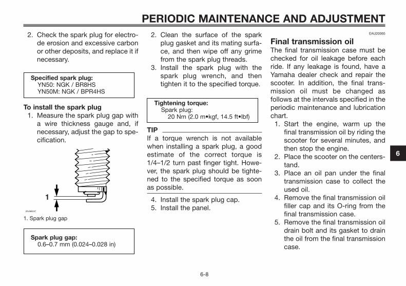
To install the spark plug1. Measure the spark plug gap with
a wire thickness gauge and, ifnecessary, adjust the gap to spe-cification.
1. Spark plug gap
2. Clean the surface of the sparkplug gasket and its mating surfa-ce, and then wipe off any grimefrom the spark plug threads.
3. Install the spark plug with thespark plug wrench, and thentighten it to the specified torque.
TIPIf a torque wrench is not availablewhen installing a spark plug, a goodestimate of the correct torque is1/4–1/2 turn past finger tight. Howe-ver, the spark plug should be tighte-ned to the specified torque as soonas possible.
4. Install the spark plug cap.5. Install the panel.
EAU20065
Final transmission oilThe final transmission case must bechecked for oil leakage before eachride. If any leakage is found, have aYamaha dealer check and repair thescooter. In addition, the final trans-mission oil must be changed asfollows at the intervals specified in theperiodic maintenance and lubricationchart.
1. Start the engine, warm up thefinal transmission oil by riding thescooter for several minutes, andthen stop the engine.
2. Place the scooter on the centers-tand.
3. Place an oil pan under the finaltransmission case to collect theused oil.
4. Remove the final transmission oilfiller cap and its O-ring from thefinal transmission case.
5. Remove the final transmission oildrain bolt and its gasket to drainthe oil from the final transmissioncase.
Tightening torque:Spark plug:
20 Nm (2.0 m•kgf, 14.5 ft•lbf)
Spark plug gap:0.6–0.7 mm (0.024–0.028 in)
1ZAUM0037
Specified spark plug:YN50: NGK / BR8HSYN50M: NGK / BPR4HS
PERIODIC MAINTENANCE AND ADJUSTMENT
6-8
6
5C2-F8199-E3 7/9/10 18:10 Página 29

1. Final transmission oil filler cap2. O-ring
6. Install the final transmission oildrain bolt and its new gasket,and then tighten the bolt to thespecified torque.
1. Final transmission oil drain bolt2. Gasket
7. Refill with the specified amountof the recommended final trans-mission oil. WARNING! Makesure that no foreign materialenters the final transmissioncase. Make sure that no oilgets on the tire or wheel. [EWA11311]
8. Install the final transmission oilfiller cap and its new O-ring, andthen tighten the oil filler cap.
9. Check the final transmission casefor oil leakage. If oil is leaking,check for the cause.
EAU40371
Air filter elementThe air filter element should be clea-ned or replaced at the intervals speci-fied in the periodic maintenance andlubrication chart. Have a Yamahadealer clean or replace the air filterelement.
Recommended final transmissionoil:
See page 8-1Oil quantity:
0.10 L (0.11 US qt, 0.09 Imp.qt)
Tightening torque:Final transmission oil drain bolt:
18 Nm (1.8 m•kgf, 13.0 ft•lbf)
PERIODIC MAINTENANCE AND ADJUSTMENT
6-9
6
5C2-F8199-E3 7/9/10 18:10 Página 30

EAU21300
Adjusting the carburetorThe carburetor is an important part ofthe engine and requires very sophisti-cated adjustment. Therefore, all car-buretor adjustments should be left toa Yamaha dealer, who has the neces-sary professional knowledge andexperience.
EAU21384
Checking the throttle gripfree play
1. Throttle grip free play
The throttle grip free play should mea-sure 4.0–6.0 mm (0.16–0.24 in) at theinner edge of the throttle grip. Perio-dically check the throttle grip free playand, if necessary, have a Yamahadealer adjust it.
EAU33601
TiresTo maximize the performance, durabi-lity, and safe operation of your vehi-cle, note the following points regar-ding the specified tires.
Tire air pressure
The tire air pressure should be chec-ked and, if necessary, adjusted befo-re each ride.
EWA10501
Operation of this vehicle withimproper tire pressure may causesevere injury or death from loss ofcontrol.
� The tire air pressure must bechecked and adjusted on cold
WARNING
ZAUM0053
PERIODIC MAINTENANCE AND ADJUSTMENT
6-10
6
5C2-F8199-E3 7/9/10 18:10 Página 31

tires (i.e., when the temperatu-re of the tires equals theambient temperature).
� The tire air pressure must beadjusted in accordance withthe riding speed and with thetotal weight of rider, passenger,cargo, and accessories appro-ved for this model.
EWA10511
Never overload your vehicle. Ope-ration of an overloaded vehiclecould cause an accident.
Tire inspection
1. Tire tread depth2. Tire sidewall
The tires must be checked beforeeach ride. If the center tread depthreaches the specified limit, if the tirehas a nail or glass fragments in it, or ifthe sidewall is cracked, have a Yama-ha dealer replace the tire immediately.
TIPThe tire tread depth limits may differfrom country to country. Alwayscomply with the local regulations.
Tire informationThis model is equipped with tubelesstires.After extensive tests, only the tires lis-ted below have been approved forthis model by Yamaha Motor Co., Ltd.
Minimum tire tread depth (frontand rear):
1.6 mm (0.06 in)
1
2
ZAUM0054
WARNING
Tire air pressure (measured oncold tires):
0–90 kg (0–198 lb):Front:
175 kPa (1.75 kgf/cm2, 25 psi, 1.75 bar)
Rear:200 kPa (2.00 kgf/cm2, 29 psi, 2.00 bar)
90–163 kg (198–359 lb):Front:
175 kPa (1.75 kgf/cm2, 25 psi, 1.75 bar)
Rear:225 kPa (2.25 kgf/cm2, 33 psi, 2.25 bar)
Maximum load*:163 kg (359 lb)
* Total weight of rider, passenger,cargo and accessories
PERIODIC MAINTENANCE AND ADJUSTMENT
6-11
6
5C2-F8199-E3 7/9/10 18:10 Página 32

EWA10470
� Have a Yamaha dealer replaceexcessively worn tires. Besidesbeing illegal, operating thevehicle with excessively worntires decreases riding stabilityand can lead to loss of control.
� The replacement of all wheeland brake related parts, inclu-ding the tires, should be left toa Yamaha dealer, who has thenecessary professional know-ledge and experience.
EAU21962
Cast wheelsTo maximize the performance, durabi-lity, and safe operation of your vehi-cle, note the following points regar-ding the specified wheels.
� The wheel rims should be chec-ked for cracks, bends, warpageor other damage before eachride. If any damage is found,have a Yamaha dealer replacethe wheel. Do not attempt eventhe smallest repair to the wheel.A deformed or cracked wheelmust be replaced.
� The wheel should be balancedwhenever either the tire or wheelhas been changed or replaced.An unbalanced wheel can resultin poor performance, adversehandling characteristics, and ashortened tire life.
EAUT1221
Checking the front brakelever free play
1. Front brake lever free play
The brake lever free play should mea-sure 2.0 – 5.0 mm (0.08 – 0.20 in) asshown. Periodically check the brakelever free play and, if necessary, havea Yamaha dealer check the brake sys-tem.
EWA10641
An incorrect brake lever free playindicates a hazardous condition inthe brake system. Do not operatethe vehicle until the brake systemhas been checked or repaired by aYamaha dealer.
WARNING
WARNING
Front tire:Size:
120/70-12 M/C 51LManufacturer/model:
VEE RUBBERCONTINENTAL / ZIPPY 1PIRELLI / SL26
Rear tire:Size:
130/70-12 M/C 56LManufacturer/model:
VEE RUBBERCONTINENTAL / ZIPPY 1PIRELLI / SL26
PERIODIC MAINTENANCE AND ADJUSTMENT
6-12
6
5C2-F8199-E3 7/9/10 18:10 Página 33

EAU22170
Adjusting the rear brakelever free play
1. Rear brake lever free play
The brake lever free play should mea-sure 5.0 – 10.0 mm (0.20 – 0.39 in) asshown. Periodically check the brakelever free play and, if necessary,adjust it as follows.To increase the brake lever free play,turn the adjusting nut at the brakeshoe plate in direction (a). To decrea-se the brake lever free play, turn theadjusting nut in direction (b).
1. Adjusting nutEWA10650
If proper adjustment cannot beobtained as described, have aYamaha dealer make this adjust-ment.
EAU22380
Checking the front brakepads and rear brake shoesThe front brake pads and the rear bra-ke shoes must be checked for wear atthe intervals specified in the periodicmaintenance and lubrication chart.
EAU22400
Front brake pads
1. Lining thickness
Check each front brake pad fordamage and measure the lining thick-ness. If a brake pad is damaged or ifthe lining thickness is less than 3.1mm (0.12 in), have a Yamaha dealerreplace the brake pads as a set.
WARNING
PERIODIC MAINTENANCE AND ADJUSTMENT
6-13
6
5C2-F8199-E3 7/9/10 18:10 Página 34

EAU43170
Rear brake shoes
1. Wear indicator2. Wear limit line
The rear brake is provided with a wearindicator, which allows you to checkthe brake shoe wear without having todisassemble the brake. To check thebrake shoe wear, check the positionof the wear indicator while applyingthe brake. If a brake shoe has worn tothe point that the wear indicator rea-ches the wear limit mark, have aYamaha dealer replace the brake sho-es as a set.
EAU32344
Checking the brake fluidlevel
1. Front brake master cylinder
Insufficient brake fluid may allow airto enter the brake system, possiblycausing it to become ineffective.Before riding, check that the brakefluid is above the minimum level markand replenish if necessary. A low bra-ke fluid level may indicate worn brakepads and/or brake system leakage. Ifthe brake fluid level is low, be sure tocheck the brake pads for wear andthe brake system for leakage.
1. Minimum level mark
Observe these precautions:� When checking the fluid level,
make sure that the top of themaster cylinder is level by turningthe handlebars.
� Use only the recommended qua-lity brake fluid, otherwise the rub-ber seals may deteriorate, cau-sing leakage and poor brakingperformance.
� Refill with the same type of brakefluid. Mixing fluids may result in aharmful chemical reaction andlead to poor braking performance.
Recommended brake fluid:DOT 4
PERIODIC MAINTENANCE AND ADJUSTMENT
6-14
6
5C2-F8199-E3 7/9/10 18:10 Página 35
� Be careful that water does notenter the master cylinder whenrefilling. Water will significantlylower the boiling point of the fluidand may result in vapor lock.
� Brake fluid may deteriorate pain-ted surfaces or plastic parts.Always clean up spilled fluidimmediately.
� As the brake pads wear, it is nor-mal for the brake fluid level togradually go down. However, ifthe brake fluid level goes downsuddenly, have a Yamaha dealercheck the cause.
EAUM1360
Changing the brake fluidHave a Yamaha dealer change thebrake fluid at the intervals specified inthe periodic maintenance and lubrica-tion chart. In addition, have the brakehose replaced every four years orwhenever it is damaged or leaking.
EAU23094
Checking and lubricating thecablesThe operation of all control cablesand the condition of the cablesshould be checked before each ride,and the cables and cable ends shouldbe lubricated if necessary. If a cable isdamaged or does not move smoothly,have a Yamaha dealer check or repla-ce it. WARNING! Damage to theouter housing of cables may resultin internal rusting and cause inter-ference with cable movement.Replace damaged cables as soonas possible to prevent unsafe con-ditions [EWA10711]
Recommended lubricant:Yamaha Chain and Cable Lube or4-stroke engine oil
PERIODIC MAINTENANCE AND ADJUSTMENT
6-15
6
5C2-F8199-E3 7/9/10 18:10 Página 36

EAU49920
Checking and lubricating thethrottle grip and cableThe operation of the throttle gripshould be checked before each ride.In addition, the cable should be lubri-cated at the intervals specified in theperiodic maintenance chart.
EAU23120
Adjusting the Autolube pumpThe operation of the throttle gripshould be checked before each ride.In addition, the cable should be lubri-cated by a Yamaha dealer at the inter-vals specified in the periodic mainte-nance chart.
EAU43641
Lubricating the front andrear brake levers
Front brake lever
Rear brake lever
PERIODIC MAINTENANCE AND ADJUSTMENT
6-16
6
5C2-F8199-E3 7/9/10 18:10 Página 37

The pivoting points of the front andrear brake levers must be lubricatedat the intervals specified in the perio-dic maintenance and lubricationchart.
EAU23192
Checking and lubricating thecenterstand
1. Centerstand
The operation of the centerstand shouldbe checked before each ride, and thepivots and metal-to-metal contact sur-faces should be lubricated if necessary.
EWA11301
If the centerstand does not move upand down smoothly, have a Yamahadealer check or repair it. Otherwise,the centerstand could contact theground and distract the operator,resulting in a possible loss of control.
EAU23272
Checking the front forkThe condition and operation of thefront fork must be checked as followsat the intervals specified in the perio-dic maintenance and lubricationchart.
To check the conditionCheck the inner tubes for scratches,damage and excessive oil leakage.
To check the operation1. Place the vehicle on a level surfa-
ce and hold it in an upright posi-tion. WARNING! To avoid injury,securely support the vehicle sothere is no danger of it fallingover. [EWA10751]
2. While applying the front brake,push down hard on the handle-bars several times to check if thefront fork compresses andrebounds smoothly.
Recommended lubricant:Lithium-soap-based grease
WARNING
Recommended lubricants:Front brake lever:
Silicone greaseRear brake lever:
Lithium-soap-based grease
PERIODIC MAINTENANCE AND ADJUSTMENT
6-17
6
5C2-F8199-E3 7/9/10 18:10 Página 38

ECA10590
If any damage is found or the frontfork does not operate smoothly,have a Yamaha dealer check orrepair it.
EAU45511
Checking the steeringWorn or loose steering bearings maycause danger. Therefore, the opera-tion of the steering must be checkedas follows at the intervals specified inthe periodic maintenance and lubrica-tion chart.
1. Place the vehicle on the centers-tand. WARNING! To avoidinjury, securely support thevehicle so there is no danger ofit falling over. [EWA10751]
2. Hold the lower ends of the frontfork legs and try to move themforward and backward. If any freeplay can be felt, have a Yamahadealer check or repair the stee-ring.
EAU23291
Checking the wheel bearings
The front and rear wheel bearingsmust be checked at the intervals spe-cified in the periodic maintenance andlubrication chart. If there is play in thewheel hub or if the wheel does notturn smoothly, have a Yamaha dealercheck the wheel bearings.
NOTICE
PERIODIC MAINTENANCE AND ADJUSTMENT
6-18
6
5C2-F8199-E3 7/9/10 18:10 Página 39

EAUM1403
Battery
1. Battery 2. Battery breather hose
A poorly maintained battery willcorrode and discharge quickly. Theelectrolyte level, battery lead connec-tions and breather hose routingshould be checked before each rideand at the intervals specified in theperiodic maintenance and lubricationchart.
To check the electrolyte level1. Place the scooter on a level sur-
face and hold it in an uprightposition.
TIPMake sure that the scooter is positio-ned straight up when checking theelectrolyte level.
2. Remove panel A. (See page 6-6). 3. Check the electrolyte level in the
battery.
1. Maximum level mark2. Minimum level mark
TIPThe electrolyte should be betweenthe minimum and maximum levelmarks.
4. If the electrolyte is at or below theminimum level mark, add distilledwater to raise it to the maximumlevel mark. NOTICE: Use onlydistilled water, as tap water
contains minerals that areharmful to the battery. [ECA10611]
EWA10760
� Electrolyte is poisonous anddangerous since it containssulfuric acid, which causessevere burns. Avoid any con-tact with skin, eyes or clothingand always shield your eyeswhen working near batteries.In case of contact, administerthe following FIRST AID.• EXTERNAL: Flush with plenty
of water.• INTERNAL: Drink large quan-
tities of water or milk andimmediately call a physician.
• EYES: Flush with water for 15minutes and seek promptmedical attention.
WARNING
PERIODIC MAINTENANCE AND ADJUSTMENT
6-19
6
5C2-F8199-E3 7/9/10 18:10 Página 40

� Batteries produce explosivehydrogen gas. Therefore, keepsparks, flames, cigarettes, etc.,away from the battery and pro-vide sufficient ventilation whencharging it in an enclosed spa-ce.
� KEEP THIS AND ALL BATTE-RIES OUT OF THE REACH OFCHILDREN.
5. Check and, if necessary, tightenthe battery lead connections andcorrect the breather hose routing.
To store the battery1. If the scooter will not be used for
more than one month, removethe battery, fully charge it, andthen place it in a cool, dry place.NOTICE: When removing thebattery, be sure the key is tur-ned to “ ”, then disconnectthe negative lead before dis-connecting the positive lead.[ECA16302]
2. If the battery will be stored formore than two months, check thespecific gravity of the electrolyte
at least once a month and fullycharge the battery whenevernecessary.
3. Fully charge the battery beforeinstallation.
4. After installation, make sure thatthe battery leads are properlyconnected to the battery termi-nals and that the breather hose isproperly routed, in good condi-tion, and not obstructed. NOTI-CE: If the breather hose is posi-tioned in such a way that theframe is exposed to electrolyteor gas expelled from the bat-tery, the frame could sufferstructural and external dama-ges. [ECA10601]
EAU23503
Replacing the fuse
1. Main fuse
The fuse holder is located behindpanel A. (See page 6-6). If the fuse is blown, replace it asfollows.
1. Turn the key to “ ” and turn offall electrical circuits.
2. Remove the blown fuse, and theninstall a new fuse of the specifiedamperage. WARNING! Do notuse a fuse of a higher ampera-ge rating than recommendedto avoid causing extensivedamage to the electrical sys-tem and possibly a fire. [EWA15131]
PERIODIC MAINTENANCE AND ADJUSTMENT
6-20
6
5C2-F8199-E3 7/9/10 18:10 Página 41

3. Turn the key to “ ” and turn onthe electrical circuits to check ifthe devices operate.
4. If the fuse immediately blowsagain, have a Yamaha dealercheck the electrical system.
EAUS1402
Replacing the headlight bulbIf the headlight bulb burns out, repla-ce it as follows.
ECA10650
Take care not to damage the follo-wing parts:
� Headlight bulbDo not touch the glass part ofthe headlight bulb to keep itfree from oil, otherwise thetransparency of the glass, theluminosity of the bulb, and thebulb life will be adversely affec-ted. Thoroughly clean off anydirt and fingerprints on theheadlight bulb using a clothmoistened with alcohol or thin-ner.
� Headlight lensDo not affix any type of tintedfilm or stickers to the headlightlens.
Do not use a headlight bulb of awattage higher than specified.
1. Do not touch the glass part of the bulb
ECA10670
It is advisable to have a Yamahadealer perform this job.
1. Place the scooter on the centers-tand.
2. Remove cowling A. (See page6-6).
3. Disconnect the headlight coupler.
NOTICE
NOTICE
Specified fuse:7.5 A
PERIODIC MAINTENANCE AND ADJUSTMENT
6-21
6
5C2-F8199-E3 7/9/10 18:10 Página 42

1. Cowling2. Headlight coupler3. Auxiliary light lead connector
4. Remove the headlight bulbcover.
1. Headlight bulb cover
5. Unhook the headlight bulb hol-der, and then remove the burnt-out bulb.
1. Headlight bulb holder
6. Place a new headlight bulb intoposition, and then secure it withthe bulb holder.
7. Install the headlight bulb cover.8. Connect the headlight coupler.9. Install the cowling.
10. Have a Yamaha dealer adjust theheadlight beam if necessary.
EAUT1262
Replacing a front turn signallight bulb
ECA10670
It is advisable to have a Yamahadealer perform this job.
1. Place the scooter on the centers-tand.
2. Remove cowling A. (See page 6-6).
3. Remove the socket (togetherwith the bulb) by turning it coun-terclockwise.
1. Turn signal light bulb socket
4. Remove the burnt-out bulb bypushing it in and turning it coun-terclockwise.
NOTICE
PERIODIC MAINTENANCE AND ADJUSTMENT
6-22
6
5C2-F8199-E3 7/9/10 18:10 Página 43
5. Insert a new bulb into the socket,push it in, and then turn it clock-wise until it stops.
6. Install the socket (together withthe bulb) by turning it clockwise.
7. Install the cowling.
EAU24283
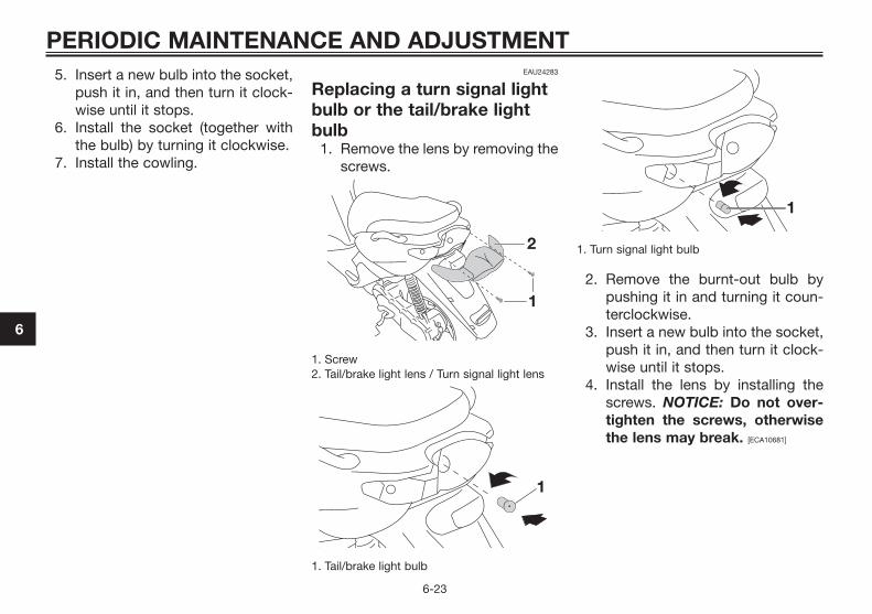
Replacing a turn signal lightbulb or the tail/brake lightbulb
1. Remove the lens by removing thescrews.
1. Screw2. Tail/brake light lens / Turn signal light lens
1. Tail/brake light bulb
1. Turn signal light bulb
2. Remove the burnt-out bulb bypushing it in and turning it coun-terclockwise.
3. Insert a new bulb into the socket,push it in, and then turn it clock-wise until it stops.
4. Install the lens by installing thescrews. NOTICE: Do not over-tighten the screws, otherwisethe lens may break. [ECA10681]
PERIODIC MAINTENANCE AND ADJUSTMENT
6-23
6
5C2-F8199-E3 7/9/10 18:10 Página 44

EAUS1151
Replacing the license platelight bulb (Depens onmodels)
1. Remove the lens by removing thescrew.
1. Screw2. License plate light bulb socket
2. Remove the burnt out bulb bypulling it out.
3. Insert a new bulb into the socket.4. Install the lens by installing the
screw. NOTICE: Do not over-tighten the screw, otherwisethe lens may break. [ECA11191]
EAU45462
Replacing the auxiliary lightbulb (Depens on models)If the auxiliary light bulb burns out,replace it as follows.
1. Place the vehicle on the centers-tand.
2. Remove cowling A. (See page 6-6).
3. Remove the auxiliary light socket(together with the bulb) by pullingit out.
1. Auxiliary light bulb socket
4. Remove the burnt-out bulb bypulling it out.
1. Auxiliary light bulb
5. Insert a new bulb into the socket.6. Install the auxiliary light socket
(together with the bulb) by pus-hing it in.
7. Install the cowling.
PERIODIC MAINTENANCE AND ADJUSTMENT
6-24
6
5C2-F8199-E3 7/9/10 18:10 Página 45
EAU25861
TroubleshootingAlthough Yamaha scooters receive athorough inspection before shipmentfrom the factory, trouble may occurduring operation. Any problem in thefuel, compression, or ignition sys-tems, for example, can cause poorstarting and loss of power.The following troubleshooting chartrepresents a quick and easy procedu-re for checking these vital systemsyourself. However, should your scoo-ter require any repair, take it to aYamaha dealer, whose skilled techni-cians have the necessary tools, expe-rience, and know-how to service thescooter properly.Use only genuine Yamaha replace-ment parts. Imitation parts may looklike Yamaha parts, but they are ofteninferior, have a shorter service life andcan lead to expensive repair bills.
EWA15141
When checking the fuel system, donot smoke, and make sure thereare no open flames or sparks in thearea, including pilot lights fromwater heaters or furnaces. Gasoli-ne or gasoline vapors can ignite orexplode, causing severe injury orproperty damage.
WARNING
PERIODIC MAINTENANCE AND ADJUSTMENT
6-25
6
5C2-F8199-E3 7/9/10 18:10 Página 46
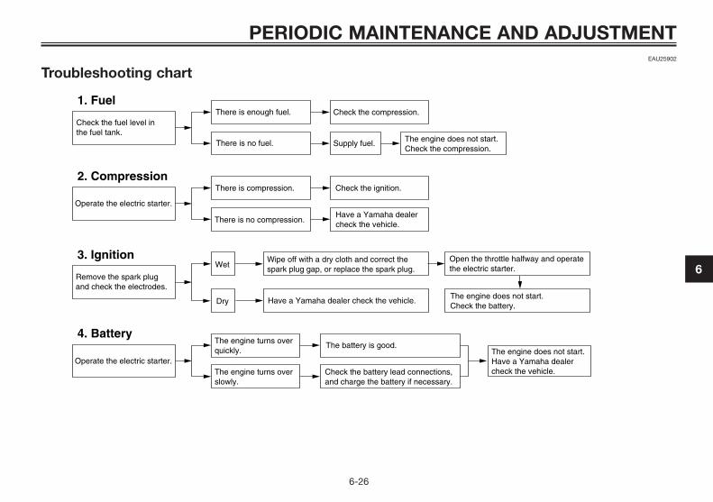
EAU25902
Troubleshooting chart
Check the fuel level inthe fuel tank.
1. FuelThere is enough fuel.
There is no fuel.
Check the compression.
Supply fuel. The engine does not start. Check the compression.
Operate the electric starter.
2. CompressionThere is compression.
There is no compression.
Check the ignition.
Have a Yamaha dealercheck the vehicle.
Remove the spark plugand check the electrodes.
3. Ignition Wipe off with a dry cloth and correct thespark plug gap, or replace the spark plug.
Have a Yamaha dealer check the vehicle.
The engine does not start.Have a Yamaha dealercheck the vehicle.
The engine does not start.Check the battery.
Operate the electric starter.
4. BatteryThe engine turns over quickly.
The engine turns over slowly.
The battery is good.
Check the battery lead connections,and charge the battery if necessary.
Dry
WetOpen the throttle halfway and operatethe electric starter.
PERIODIC MAINTENANCE AND ADJUSTMENT
6-26
6
5C2-F8199-E3 7/9/10 18:10 Página 47
EAU37833
Matte color cautionECA15192
Some models are equipped withmatte colored finished parts. Besure to consult a Yamaha dealer foradvice on what products to usebefore cleaning the vehicle.Using a brush, harsh chemical pro-ducts or cleaning compoundswhen cleaning these parts willscratch or damage their surface.Wax also should not be applied toany matte colored finished parts.
EAU26094
CareWhile the open design of a scooterreveals the attractiveness of the tech-nology, it also makes it more vulnera-ble. Rust and corrosion can developeven if high-quality components areused. A rusty exhaust pipe may gounnoticed on a car, however, itdetracts from the overall appearanceof a scooter. Frequent and propercare does not only comply with theterms of the warranty, but it will alsokeep your scooter looking good,extend its life and optimize its perfor-mance.
Before cleaning1. Cover the muffler outlet with a
plastic bag after the engine hascooled down.
2. Make sure that all caps andcovers as well as all electricalcouplers and connectors, inclu-ding the spark plug cap, aretightly installed.
3. Remove extremely stubborn dirt,like oil burnt onto the crankcase,with a degreasing agent and a
brush, but never apply such pro-ducts onto seals, gaskets andwheel axles. Always rinse the dirtand degreaser off with water.
CleaningECA10783
� Avoid using strong acidic whe-el cleaners, especially on spo-ked wheels. If such productsare used on hard-to-removedirt, do not leave the cleaner onthe affected area any longerthan instructed. Also, tho-roughly rinse the area off withwater, immediately dry it, andthen apply a corrosion protec-tion spray.
� Improper cleaning can damageplastic parts (such as cowlings,panels, windshields, headlightlenses, meter lenses, etc.) andthe mufflers. Use only a soft,clean cloth or sponge withwater to clean plastic. Howe-ver, if the plastic parts cannotbe thoroughly cleaned withwater, diluted mild detergent
NOTICE
NOTICE
SCOOTER CARE AND STORAGE
7-1
7
5C2-F8199-E3 7/9/10 18:10 Página 48

with water may be used. Besure to rinse off any detergentresidue using plenty of water,as it is harmful to plastic parts.
� Do not use any harsh chemicalproducts on plastic parts. Besure to avoid using cloths orsponges which have been incontact with strong or abrasivecleaning products, solvent orthinner, fuel (gasoline), rustremovers or inhibitors, brakefluid, antifreeze or electrolyte.
� Do not use high-pressure was-hers or steam-jet cleaners sin-ce they cause water seepageand deterioration in the follo-wing areas: seals (of wheel andswingarm bearings, fork andbrakes), electric components(couplers, connectors, instru-ments, switches and lights),breather hoses and vents.
� For scooters equipped with awindshield: Do not use strongcleaners or hard sponges asthey will cause dulling or scrat-ching. Some cleaning com-pounds for plastic may leave
scratches on the windshield.Test the product on a small hid-den part of the windshield tomake sure that it does not lea-ve any marks. If the windshieldis scratched, use a qualityplastic polishing compoundafter washing.
After normal useRemove dirt with warm water, a milddetergent, and a soft, clean sponge,and then rinse thoroughly with cleanwater. Use a toothbrush or bottle-brush for hard-to-reach areas. Stub-born dirt and insects will come offmore easily if the area is covered witha wet cloth for a few minutes beforecleaning.
After riding in the rain, near the sea oron salt-sprayed roadsSince sea salt or salt sprayed on theroads during winter are extremelycorrosive in combination with water,carry out the following steps aftereach ride in the rain, near the sea oron salt-sprayed roads.
TIPSalt sprayed on roads in the wintermay remain well into spring.
1. Clean the scooter with cold waterand a mild detergent after theengine has cooled down. NOTI-CE: Do not use warm watersince it increases the corrosiveaction of the salt. [ECA10791]
2. Apply a corrosion protectionspray on all metal, includingchrome- and nickel-plated, surfa-ces to prevent corrosion.
After cleaning1. Dry the scooter with a chamois or
an absorbing cloth.2. Use a chrome polish to shine
chrome, aluminum and stainless-steel parts, including the exhaustsystem. (Even the thermally indu-ced discoloring of stainless-steelexhaust systems can be removedthrough polishing.)
SCOOTER CARE AND STORAGE
7-2
7
5C2-F8199-E3 7/9/10 18:10 Página 49
3. To prevent corrosion, it is recom-mended to apply a corrosion pro-tection spray on all metal, inclu-ding chrome- and nickel-plated,surfaces.
4. Use spray oil as a universal clea-ner to remove any remaining dirt.
5. Touch up minor paint damagecaused by stones, etc.
6. Wax all painted surfaces.7. Let the scooter dry completely
before storing or covering it.EWA10942
Contaminants on the brakes ortires can cause loss of control.
� Make sure that there is no oil orwax on the brakes or tires. Ifnecessary, clean the brakediscs and brake linings with aregular brake disc cleaner oracetone, and wash the tireswith warm water and a milddetergent.
� Before operating the scootertest its braking performanceand cornering behavior.
ECA10800
� Apply spray oil and wax spa-ringly and make sure to wipeoff any excess.
� Never apply oil or wax to anyrubber and plastic parts, buttreat them with a suitable careproduct.
� Avoid using abrasive polishingcompounds as they will wearaway the paint.
TIP� Consult a Yamaha dealer for
advice on what products to use.� Washing, rainy weather or humid
climates can cause the headlightlens to fog. Turning the headlighton for a short period of time willhelp remove the moisture fromthe lens.
EAU26303
Storage
Short-termAlways store your scooter in a cool,dry place and, if necessary, protect itagainst dust with a porous cover. Besure the engine and the exhaust sys-tem are cool before covering the sco-oter.
ECA10820
� Storing the scooter in a poorlyventilated room or covering itwith a tarp, while it is still wet,will allow water and humidity toseep in and cause rust.
� To prevent corrosion, avoiddamp cellars, stables (becauseof the presence of ammonia)and areas where strong chemi-cals are stored.
Long-termBefore storing your scooter for seve-ral months:
1. Follow all the instructions in the“Care” section of this chapter.
NOTICE
NOTICE
WARNING
SCOOTER CARE AND STORAGE
7-3
7
5C2-F8199-E3 7/9/10 18:10 Página 50
2. Drain the carburetor float cham-ber by loosening the drain bolt;this will prevent fuel depositsfrom building up. Pour the drai-ned fuel into the fuel tank.
3. Fill up the fuel tank and add fuelstabilizer (if available) to preventthe fuel tank from rusting and thefuel from deteriorating.
4. Perform the following steps toprotect the cylinder, piston rings,etc. from corrosion.a. Remove the spark plug cap
and spark plug.b. Pour a teaspoonful of engine
oil into the spark plug bore.c. Install the spark plug cap
onto the spark plug, and thenplace the spark plug on thecylinder head so that theelectrodes are grounded.(This will limit sparking duringthe next step.)
d. Turn the engine over severaltimes with the starter. (Thiswill coat the cylinder wall withoil.) WARNING! To preventdamage or injury from spar-king, make sure to ground
the spark plug electrodeswhile turning the engineover. [EWA10951]
e. Remove the spark plug capfrom the spark plug, and theninstall the spark plug and thespark plug cap.
5. Lubricate all control cables andthe pivoting points of all leversand pedals as well as of thesidestand/centerstand.
6. Check and, if necessary, correctthe tire air pressure, and then liftthe scooter so that both of itswheels are off the ground. Alter-natively, turn the wheels a littleevery month in order to preventthe tires from becoming degra-ded in one spot.
7. Cover the muffler outlet with aplastic bag to prevent moisturefrom entering it.
8. Remove the battery and fullycharge it. Store it in a cool, dryplace and charge it once amonth. Do not store the battery inan excessively cold or warm pla-ce [less than 0 °C (30 °F) or morethan 30 °C (90 °F)]. For more
information on storing the bat-tery, see page 6-19.
TIPMake any necessary repairs beforestoring the scooter.
SCOOTER CARE AND STORAGE
7-4
7
5C2-F8199-E3 7/9/10 18:10 Página 51
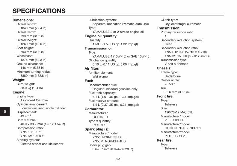
Dimensions:Overall length:
1840 mm (72.4 in)Overall width:
793 mm (31.2 in)Overall height:
1260 mm (49.6 in)Seat height:
793 mm (31.2 in)Wheelbase:
1275 mm (50.2 in)Ground clearance:
146 mm (5.75 in)Minimum turning radius:
3880 mm (152.8 in)Weight:
Curb weight:88.0 kg (194 lb)
Engine:Engine type:
Air cooled 2-strokeCylinder arrangement:
Forward-inclined single cylinderDisplacement:
49 cm3
Bore x stroke:40.0 x 39.2 mm (1.57 x 1.54 in)
Compression ratio:YN50: 11.00 :1YN50M: 10.00 :1
Starting system:Electric starter and kickstarter
Lubrication system:Separate lubrication (Yamaha autolube)
Type:YAMALUBE 2 or 2-stroke engine oil
Engine oil quantity:Quantity:
1.50 L (1.59 US qt, 1.32 Imp.qt)Transmission oil:
Type:YAMALUBE 4 (10W-40) or SAE 10W-40
Oil change quantity:0.10 L (0.11 US qt, 0.09 Imp.qt)
Air filter:Air filter element:
Wet elementFuel:
Recommended fuel:Regular unleaded gasoline only
Fuel tank capacity:6.1 L (1.61 US gal, 1.34 Imp.gal)
Fuel reserve amount:1.4 L (0.37 US gal, 0.31 Imp.gal)
Carburetor:Manufacturer:
GURTNERType x quantity:
PY12 x 1Spark plug (s):
Manufacturer/model:YN50: NGK/BR8HSYN50M: NGK/BPR4HS
Spark plug gap:0.6–0.7 mm (0.024–0.028 in)
Clutch type:Dry, centrifugal automatic
Transmission:Primary reduction ratio:
1Secondary reduction system:
GearSecondary reduction ratio:
YN50: 12.923 (52/13 x 42/13)YN50M: 15.000 (52/12 x 45/13)
Transmission type:V-belt automatic
Chassis:Frame type:
UnderboneCaster angle:
26.50 ºTrail:
92.6 mm (3.65 in)Front tire:
Type:Tubeless
Size:120/70-12 M/C 51L
Manufacturer/model:VEE RUBBER
Manufacturer/model:CONTINENTAL / ZIPPY 1
Manufacturer/model:PIRELLI / SL26
Rear tire:Type:
Tubeless
SPECIFICATIONS
8-1
8
5C2-F8199-E3 7/9/10 18:10 Página 52

Size:130/70-12 M/C 56L
Manufacturer/model:VEE RUBBER
Manufacturer/model:CONTINENTAL / ZIPPY 1
Manufacturer/model:PIRELLI / SL26
Loading:Maximum load:
163 kg (359 lb)(Total weight of rider, passenger, cargoand accessories)
Tire air pressure (measured on coldtires):
Loading condition:0–90 kg (0–198 lb)
Front:175 kPa (1.75 kgf/cm2, 25 psi, 1.75 bar)
Rear:200 kPa (2.00 kgf/cm2, 29 psi, 2.00 bar)
Loading condition:90–163 kg (198–359 lb)
Front:175 kPa (1.75 kgf/cm2, 25 psi, 1.75 bar)
Rear:225 kPa (2.25 kgf/cm2, 33 psi, 2.25 bar)
Front wheel:Wheel type:
Cast wheelRim size:
12 M/C xMT3.50Rear wheel:
Wheel type:Cast wheel
Rim size:12 M/C xMT3.50
Front brake:Type:
Single disc brakeOperation:
Right hand operationRecommended fluid:
DOT 4Rear brake:
Type:Drum brake
Operation:Left hand operation
Front suspension:Type:
Telescopic forkSpring/shock absorber type:
Coil spring/oil damperWheel travel:
70.0 mm (2.76 in)Rear suspension:
Type:Unit swing
Spring/shock absorber type:Coil spring/oil damper
Wheel travel:60.0 mm (2.36 in)
Electrical system:Ignition system:
CDICharging system:
AC magneto
Battery:Model:
YB 4L-BVoltage, capacity:
12 V, 4.0 AhHeadlight:
Bulb type:Halogen bulb
Bulb voltage, wattage x quantity:Headlight:
12 V, 35 W/35 W x 1Tail/brake light:
12 V, 21.0 W/5.0 W x 1Front turn signal light:
12 V, 10.0 W x 2Rear turn signal light:
12 V, 10.0 W x 2License plate light:
12 V, 5.0 W x 1Meter lighting:
LEDHigh beam indicator light:
LEDOil level warning light:
LEDTurn signal indicator light:
LEDFuel level warning light:
LEDFuses:
Main Fuse:7.5 A
SPECIFICATIONS
8-2
8
5C2-F8199-E3 7/9/10 18:10 Página 53
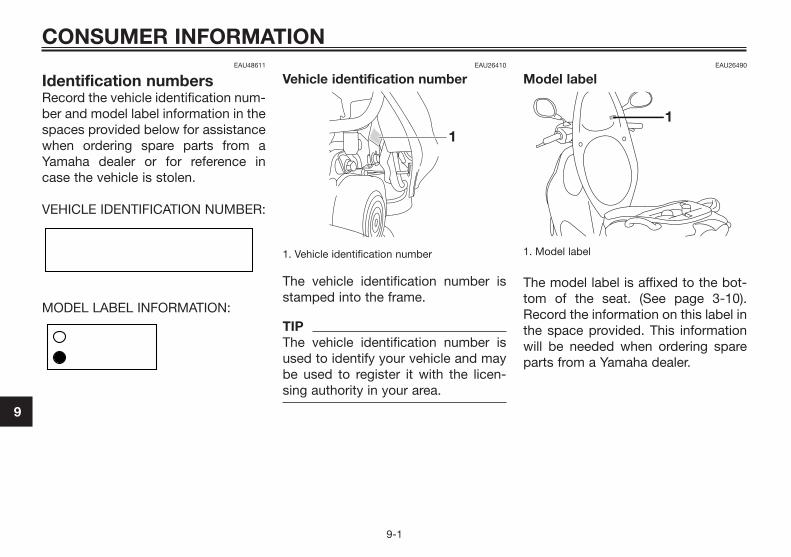
EAU48611
Identification numbersRecord the vehicle identification num-ber and model label information in thespaces provided below for assistancewhen ordering spare parts from aYamaha dealer or for reference incase the vehicle is stolen.
VEHICLE IDENTIFICATION NUMBER:
MODEL LABEL INFORMATION:
EAU26410
Vehicle identification number
1. Vehicle identification number
The vehicle identification number isstamped into the frame.
TIPThe vehicle identification number isused to identify your vehicle and maybe used to register it with the licen-sing authority in your area.
EAU26490
Model label
1. Model label
The model label is affixed to the bot-tom of the seat. (See page 3-10).Record the information on this label inthe space provided. This informationwill be needed when ordering spareparts from a Yamaha dealer.
CONSUMER INFORMATION
9-1
9
5C2-F8199-E3 7/9/10 18:10 Página 54
2-stroke engine oil ...................................3-10A
Acceleration and deceleration ...................5-2Air filter element .........................................6-9Autolube pump, adjusting........................6-16Auxiliary light bulb, replacing...................6-24
BBattery......................................................6-19Brake fluid level, checking .......................6-14Brake fluid, changing ...............................6-15Brake lever, front ........................................3-6Brake lever, rear .........................................3-6Brake levers, lubricating ..........................6-16Brake pads and shoes, checking ............6-13Braking.......................................................5-2
CCables, checking and lubricating ............6-15Carburetor,adjusting.................................6-10Care............................................................7-1Catalytic converter .....................................3-9Centerstand, checking and lubricating....6-17Cowling and panel, removing and
installing...................................................6-6D
Dimmer switch ...........................................3-6E
Engine break-in ..........................................5-3F
Final transmission oil .................................6-8Front brake lever free play, checking.......6-12Front fork, checking.................................6-17Fuel ............................................................3-8Fuel and 2-stroke engine oil tank caps .....3-7Fuel consumption, tips for reducing..........5-3
Fuel level warning light ..............................3-2Fuel tank breather/overflow hose ..............3-9Fuse, replacing.........................................6-20
HHandlebar switches ...................................3-5Headlight bulb, replacing.........................6-21High beam indicator light...........................3-2Horn switch................................................3-6
IIdentification numbers ...............................9-1Indicator and warning lights ......................3-2
KKickstarter ................................................3-10
LLicense plate light bulb, replacing...........6-24Luggage hook ..........................................3-12
MMain switch/steering lock ..........................3-1Maintenance and lubrication, periodic ......6-3Maintenance, emission control system .....6-2Matte color, caution ...................................7-1Model label ................................................9-1Multi-function display ................................3-3
OOil level warning light.................................3-2
PParking .......................................................5-4Part locations .............................................2-1
RRear brake lever free play, adjusting .......6-13
SSafe-riding points.......................................1-5Safety information......................................1-1Seat ..........................................................3-10
Spark plug, checking .................................6-7Specifications.............................................8-1Start switch ................................................3-6Starting a cold engine................................5-1Starting off .................................................5-1Steering, checking ...................................6-18Storage.......................................................7-3Storage compartment..............................3-11
TThrottle grip and cable, checking and
lubricating ..............................................6-16Throttle grip free play, checking ..............6-10Tires .........................................................6-10Troubleshooting .......................................6-25Troubleshooting chart ..............................6-26Turn signal indicator light...........................3-2Turn signal light bulb (front), replacing ....6-22Turn signal light bulb or tail/brake light
bulb, replacing .......................................6-23Turn signal switch ......................................3-6
VVehicle identification number.....................9-1
WWheel bearings, checking........................6-18Wheels .....................................................6-12
INDEX
5C2-F8199-E3 7/9/10 18:10 Página 55

5C2-F8199-E3 7/9/10 18:10 Página 56

5C2-F8199-E3 7/9/10 18:10 Página 57

5C2-F8199-E3 7/9/10 18:10 Página 58

5C2-F8199-E3 7/9/10 18:10 Página 59

YAMAHA MOTOR ESPAÑA, S.A.PRINTED IN SPAIN
2010.09(E)
5C2-F8199-E3 7/9/10 18:10 Página 60