your reliable partner - pei-france.com
TRANSCRIPT

www. .com
Torsionally Rigid Shaft Couplings
K.950.V15.EN
ROBA®-DS
your reliable partner

ROBA®-DSTechnologically superior
• Non-sensitive to alternating loads of up to 100 % of the nominal torque • Low mass inertia due to high performance density • Completely backlash-free up to nominal torque • High misalignment compensation capability at low restoring forces • High torsional rigidity up to nominal torque • Completely wear and maintenance-free • Optimum construction shape due to large variant range
Increased frictional locking due to sand-blasted disk
Optimised choice due to large bores
The ROBA®-DS transmits drive torques up to the nominal torque completely backlash-free and with permanently high torsional spring rigidity. Problems to be found on other commercially available couplings, such as denting the disks or overcoming the frictional locking, are not a problem on our couplings. The specified shaft misalignments can be 100 % utilized without affecting the transmittable torque. This guarantees unlimited use.
Diagram: A ROBA®-DS coupling rigidity characteristic curve in comparison to a typical rival product with frictionally-locking/positively-locking torque transmission.
FEM-optimised disk shape
Completely backlash-free due to conical connection
Extremely short double-jointed design
Diverse shaft/hub connections
-0,08 -0,04 0 0,04 0,08 0,12 0,16 0,2
Torsional angle [°]
750
500
250
0
-250
-500
-750
Torq
ue [
Nm
]
0,01°
0,12°
Rival product ROBA®-DS 64
According to German notation, decimal points in this catalogue are represented with a comma (e.g. 0,5 instead of 0.5).
We reserve the right to make dimensional and constructional alterations.
ROBA®-DS couplings are also available in ATEX design according to the directive 94/9 EC (ATEX 95).
ROBA®-DS couplings are also available in rustproof design.
your reliable partner
2

Backlash-free servo couplings (Aluminium) Page 8
Sizes 3 to 15 Disk pack-Servowith 4x divisions and 6x divisions
Shaft connection
Nominal torques Clamping hub Page 835 to 150 Nm Hub with tapered bore Page 8
Bores Split clamping hub Page 1010 to 45 Shrink disk hub Page 12
Angular misalignment 1°
Backlash-free all-steel couplings Page 14
Sizes 16 to 160 Disk pack-HT with 6x divisions
Shaft connection
Nominal torques Key hub Page 14300 to 2600 Nm Key hub large Page 16
Clamping hub Page 18Bores Shrink disk hub external clamping Page 20
14 to 110 External shrink disk hub Page 21Angular misalignment 0,7° Shrink disk hub external/internal clamping Page 22
Shrink disk hub large Page 24Flange Page 26
Sizes 16 to 160 Disk pack-HFwith 6x divisions
Shaft connection
Nominal torques Key hub Page 28190 to 1600 Nm Key hub large Page 30
Clamping hub Page 32Bores Clamping ring hub Page 34
14 to 110 Shrink disk hub external clamping Page 36Angular misalignment 1° External shrink disk hub Page 37
Shrink disk hub external/internal clamping Page 38Shrink disk hub large Page 40Split clamping hub Page 42Flange Page 44
Sizes 180 to 2200 Disk packwith 8x divisions
Shaft connection
Nominal torques Key hub Page 462100 to 24000 Nm Shrink disk hub external clamping Page 48
Bores External shrink disk hub Page 4940 to 170 Split clamping hub Page 50
Angular misalignment 0,5° Flange Page 52
Sizes 2200 to 11000 Shaft connection
Nominal torques Customer-specific adaptations Page 5422 to 110 kNm e. g. :
Angular misalignment 0,4° key hub, shrink disk hub, flange
Variable Length Sleeve S/CFRP Sleeve/Options and variants on intermediate shafts Page 56
Safe Against Overload Page 59
Transmittable Torques for Shrink disk, Split clamping, Clamping ring, Clamping and Key hubs Page 60
Installation Examples Page 62
Integrated Torque Measurement Page 64
Dimensioning, Size Selection Page 68
Technical Explanations Page 69
your reliable partner
3

your reliable partner
Configuration Possibilities/Standard Designs
Clamping hubType 95_.4_ _
Shrink disk hubType 95_.2_ _
Single-jointed coupling without connection plate
or sleeveType 950._ _0
Connection plate Type 951._ _1
Type 951._ _2 (only for split clamping hubs)
Disk pack
Type 950._ _0on single-jointed
couplings
Type 951._ _ _on double-jointed
couplings
Disk packType 951._ _ _
Sleeve SType 951._ _3
Clamping hubType 95_.4_ _
Shrink disk hubType 95_.2_ _
Hub with tapered boreType 95_.5_ _Sizes 3 and 6
ROBA®-DS backlash-free servo couplings
Split clamping hubType 95_.8_ _double-jointed couplings
Split clamping hubType 95_.8_ _double-jointed couplings
4

your reliable partner
Type Key/Order Number
Hub 1 Hub 2Shrink disk hub Clamping hub Split clamping hub
2 4 8
2 4 5 8
Shrink disk hub Clamping hub Hub with tapered bore Split clamping hub
__ / 9 5 __ . __ __ __ / __ / __ / __
Size 3 6 10 15
Single-jointed coupling
Double-jointed coupling
0
1
Single-jointed coupling
Double-jointed coupling Connection plate Connection plate HSK Sleeve S
0
1 2 3
Bore Hub 1 ø
Bore Hub 2 ø
Operating Speed [rpm]
for
Sleeve S
Sizes 3 to 15
Type Key/Order Number
ROBA®-DS backlash-free servo couplings
5

your reliable partner
Configuration Possibilities/Standard Designs
Key HubType 95_.0_ _All sizes
Clamping ring hubType 95_.4_ _Sizes 16 to 160Disk pack HF
Shrink disk hubexternal clampingType 95_.2_ _All sizes
Split clamping hubType 95_.8_ _All sizes, double-jointed couplingsDisk pack HF
FlangeType 95_.6_ _All sizes
Key HublargeType 95_.1_ _Sizes 16 to 160
Key hubinternalType 95_.7_ _Sizes 180 to 2200Only with sleeve 1
Shrink disk hublargeType 95_.9_ _Sizes 16 to 160
Key HubType 95_.0_ _All sizes
Clamping ring hubType 95_.4_ _Sizes 16 to 160Disk pack HF
Shrink disk hubexternal clampingType 95_.2_ _All sizes
Split clamping hubType 95_.8_ _All sizes, double-jointed couplingsDisk pack HF
FlangeType 95_.6_ _All sizes
Key HublargeType 95_.1_ _Sizes 16 to 160
Key hubinternalType 95_.7_ _Sizes 180 to 2200Only with sleeve 1
Shrink disk hubType 95_.9_ _Sizes 16 to 160
Shrink disk hubinternal clampingType 95_.3_ _Sizes 16 to 160
ROBA®-DS backlash-free all-steel couplings
Clamping hubType 95_.5_ _Sizes 16 to 160
Clamping hubType 95_.5_ _Sizes 16 to 160
Single-jointed coupling without connection plate
or sleeveType 95_._ _0
Connection plate Type 95_._ _1
Disk pack HT
Type 952._ _0on single-jointed
couplings
Type 953._ _ _on double-jointed
couplings
Disk pack HTType 953._ _ _
Sleeve 1Type 95_._ _2
Sleeve SType 95_._ _3
Sleeve CRDType 95_._ _4
CFRP sleeveType 95_._ _5
Disk pack HF
Type 950._ _0on single-jointed
couplings
Type 951._ _ _on double-jointed
couplings
Disk pack HFType 951._ _ _
6

your reliable partner
Type Key/Order Number
Hub 1 Hub 2Key hub, standard Shrink disk hub, external clamping Flange Key hub, internal Split clamping hub
Key hub, standard Shrink disk hub, external clamping Flange Key hub, internal Split clamping hub
0 2 6 7 8
0 2 6 7 8
__ / 9 5 __ . __ __ __ / __ / __ / __
Size 180 300 500 850 1400 2200
Single-jointed coupling Double-jointed coupling
0 1
Single-jointed coupling
Double-jointed coupling Connection plate Sleeve 1 Sleeve SSleeve CRD CFRP sleeve
0 1 2 345
Bore Hub 1 ø
Bore Hub 2 ø
Operating Speed [rpm]
for
Sleeve S Sleeve CRD CFRP sleeve
Type Key/Order Number
Hub 1 Hub 2Key hub, standard Key hub, large Shrink disk hub, external clamping Shrink disk hub, internal clamping Clamping ring hubClamping hub Flange Split clamping hub Shrink disk hub, large
Key hub, standard Key hub, large Shrink disk hub, external clamping Clamping ring hubClamping hub Flange Split clamping hub Shrink disk hub, large
0 1 2 45 6 8 9
0 1 2 3 45 6 8 9
__ / 9 5 __ . __ __ __ / __ / __ / __
Size 16 25 40 64 100 160
Single-jointed coupling Disk pack HF Double-jointed coupling Disk pack HF Single-jointed coupling Disk pack HT Double-jointed coupling Disk pack HT
0 1 2 3
Single-jointed coupling Double-jointed coupling Connection plate Sleeve 1 Sleeve SSleeve CRD CFRP sleeve
0 1 2 345
Bore Hub 1 ø
Bore Hub 2 ø
Operating Speed [rpm]
for
Sleeve S Sleeve CRD CFRP sleeve
Sizes 180 to 2200
Sizes 16 to 160
Type Key/Order Number
ROBA®-DS backlash-free all-steel couplings
7

Ll
ØD
Ød R
S
l3 l4
l2
ØD
1
Ød F
ØD
2
ØD SK
your reliable partner
Fig. 1: Type 950.440
Single-jointed coupling with clamping hubs Alternative shaft connection
ROBA®-DS Sizes 3 to 15
Technical Data and Main DimensionsSize
3 6 10 15Nominal torque 1) TKN [Nm] 35 60 100 150
Peak torque 2) TKS [Nm] 52 90 150 225
Alternating torque TKW [Nm] 21 36 60 90
Outer diameter D [mm] 45 56 69 79
Minimum hub bore 3) 4) dRH7
min [mm] 10 14 19 25
Maximum hub bore 3) 4) dRH7
max [mm] 20 28 35 42
Maximum speed 5)with clamping hub nmax [rpm] 13500 10800 9000 7800
with hub with tapered bore nmax [rpm] 22500 18000 15000 13000
Permittedmisalignments 6)
permitted axial displacement 7) 8) ∆Ka [mm] 0,5 0,7 0,9 1,1
permitted radial misalignment 7)
with connection plate ∆Kr [mm] 0,15 0,15 0,2 0,2
with sleeve S ∆Kr H [mm] (HS - S) x 0,0174
Spring rigiditytorsion 9)
disk pack CT LP [103 Nm/rad] 17 35 60 145
tube sleeve S CT H rel. [106 Nm mm/rad] 3,3 6,8 12 19
angular spring rigidity 10) [Nm/rad] 43 64 76 229
Size 3 6 10 15DSK 47 - 71 -d3 17 22,5 35,5 40HS acc. customer specificationsh2 40 50 60 70L 48,5 52,6 66,9 69,9L2 59 64,7 79,3 82,8L6 dependent on HS
l 23 25 32 33,5S 2,5 2,6 2,9 2,9U 28 32 40 46U1 13 14,7 15,3 15,8
Hub withtapered bore
dF ± 0,05 11 14 11 14 16 - -D1 27 27 35 35 35 - -D2 16 21 16 25 25 - -l2 23 30 23 30 40 - -l3 13 20 11 18 28 - -l4 6 10 6 10 10 - -
Dimensions [mm] Mass Moments of Inertia J [10-3 kgm2]Size 3 6 10 15
Disk pack 11) 0,006 0,018 0,035 0,077
Clamping hub 12) 0,021 0,054 0,164 0,295
Hub with tapered bore 12) 0,012 0,039 - -
Connection plate 0,018 0,050 0,121 0,208
Sleeve S with HS = 1000 mm 0,349 0,755 1,373 2,341
Sleeve S per 1000 mm tube 0,323 0,682 1,175 1,981
Weight [kg]
Size 3 6 10 15
Disk pack 11) 0,023 0,041 0,050 0,077
Clamping hub 12) 0,070 0,112 0,221 0,297
Hub with tapered bore 12) 0,053 0,121 - -
Connection plate 0,063 0,111 0,161 0,218
Sleeve S with HS = 1000 mm 1,009 1,361 1,678 2,079
Sleeve S per 1000 mm tube 0,938 1,231 1,443 1,762
Fig. 2: Type 95_._5_(only Sizes 3 and 6)
e.g. for Fanuc motors
Hub with tapered bore
1) Valid for max. permitted shaft misalignment.2) Valid for unchanging load direction, max. load cycles ≤ 105.3) Recommended hub/shaft tolerance: H7/k64) Preferred bores and transmittable torques dependent on bore see page 61.5) Not valid for coupling with sleeve S.6) The permitted misalignments may not simultaneously reach their
maximum values.7) The values refer to couplings with 2 disk packs.
8) Only permitted as a static or virtually static value.9) The CT-value of a
double-jointed coupling can be roughly calculated as follows:
10) The values refer to 1 disk pack. 11) Mass moments of inertia and weights are valid for 1 disk pack.12) Mass moments of inertia and weights are valid for maximum bore.
1 CT tot. = 2 HS [mm] - 2 S [mm]
CT LP CT H rel.
1,0°
rotation circle diameter ØDSK of the clamping screws
8

L2
l
ØD
Ød 3
Ød R
S
U1
L6
ØD
Ød R
S U
HS
h 2
l
your reliable partner
Double-jointed coupling with sleeve S (special length) and clamping hubs
Fig. 4: Type 951.443 (Sleeve S: HS, L6)
ROBA®-DS Sizes 3 to 15
2,0°
∆Kr
2,0°
∆Kr H
Double-jointed coupling with connection plate and clamping hubs
Fig. 3: Type 951.441
Backlash-free All-steel Couplings Page 14
Safe Against Overload Page 59
Transmittable Torques for Clamping Hubs Page 61
Installation Examples Page 62
Dimensioning, Size Selection Page 68
Technical Explanations Page 69
Order Number
HUB 24 5
Clamping hub** Hub with tapered bore***
__ / 9 5 __ . 4 __ __ / __ / __ / __ / __
Sizes 3 to 15
Single-jointed coupling Double-jointed coupling
0 1
Single-jointed coupling Connection plate Sleeve S
0
1 3
Bore* Hub 1 ø
(Dim. page 8)
Bore* Hub 2 ø
(Dim. page 8)
Sleeve length
HS
[mm]
Operating speed
nS
[rpm]
for special sleeve S
Example: 10 / 951.441 / Hub 1 – ø 25 H7 / Hub 2 – ø 25 H7 * Standard H7, other tolerances possible ** Clamping hub also available with keyway
*** Only Sizes 3 and 6
9

ØDSKØ
DØ
d 3
Ød H
S
L2
U1
l3
l
your reliable partner
Technical Data and Main DimensionsSize
3 6 10 15Nominal torque 1) TKN [Nm] 35 60 100 150
Peak torque 2) TKS [Nm] 52 90 150 225
Alternating torque TKW [Nm] 21 36 60 90
Outer diameter D [mm] 45 56 69 79
Minimum hub bore 3) 4) dHH7
min [mm] 10 14 19 25
Maximum hub bore 3) 4) dHH7
max [mm] 20 28 35 42
Maximum speed 5) nmax [rpm] 3000 3000 3000 3000
Permittedmisalignments 6)
permitted axial displacement 7) 8) ∆Ka [mm] 0,5 0,7 0,9 1,1
permitted radial misalignment 7)
with connection plate HSK ∆Kr HSK [mm] 0,35 0,4 0,45 0,5
with sleeve S ∆Kr H [mm] (HS - S) x 0,0174
Spring rigidity torsion 9)
disk pack CT LP [103 Nm/rad] 17 35 60 145
tube sleeve S CT H rel. [106 Nm mm/rad] 3,3 6,8 12 19
angular spring rigidity 10) [Nm/rad] 43 64 76 229
Optional keyway design according to DIN 6885/1 possible (up to bore dH = 18 mm on Size 3, up to bore dH = 22 mm on Size 6, for all bores on Sizes 10 and 15)
Fig. 5: Type 951.882
rotation circle diameter ØDSK of the clamping screws
Double-jointed coupling with connection plate and split clamping hubs
ROBA®-DS Sizes 3 to 15
Dimensions [mm] Mass Moments of Inertia J [10-3 kgm2]Size 3 6 10 15
Disk pack 11) 0,006 0,018 0,035 0,077
Split clamping hub 12) 0,018 0,048 0,143 0,266
Connection plate HSK 0,017 0,044 0,119 0,264
Sleeve S with HS = 1000 mm 0,349 0,755 1,373 2,341
Sleeve S per 1000 mm tube 0,323 0,682 1,175 1,981
Weight [kg]
Size 3 6 10 15Disk pack 11) 0,023 0,041 0,050 0,077
Split clamping hub 12) 0,060 0,098 0,195 0,270
Connection plate HSK 0,057 0,096 0,161 0,270
Sleeve S with HS = 1000 mm 1,009 1,361 1,978 2,079
Sleeve S per 1000 mm tube 0,938 1,231 1,443 1,762
Size 3 6 10 15DSK 47 - 71 -
d3 17 22,5 35,5 40
HS acc. customer specifications
h2 40 50 60 70
L2 69 75,2 93,8 100,8
L6 dependent on HS
l 23 25 32 33,5
S 2,5 2,6 2,9 2,9
U 28 32 40 46
U1 23 25,2 29,8 33,8
1) Valid for unchanging load direction as well as for max. permitted shaft misalignment. When the load direction changes, max. 60% of the stated nominal torque is permitted.
2) Valid for unchanging load direction, max. load cycles ≤ 105.3) Recommended hub/shaft tolerance: H7/g64) Preferred bores and transmittable torques dependent on bore see page 60.5) Not valid for coupling with sleeve S.6) The permitted misalignments may not simultaneously reach their
maximum values.7) The values refer to couplings with 2 disk packs.8) Only permitted as a static or virtually static value.
9) The CT-value of a double-jointed coupling can be roughly calculated as follows:
10) The values refer to 1 disk pack. 11) Mass moments of inertia and weights are valid for 1 disk pack.12) Mass moments of inertia and weights are valid for maximum bore.
1CT ges. = 2 HS [mm] - 2 S [mm]
CT LP CT H rel.
2,0°
∆Kr
10

L6
Ød H
S
HS
h 2 U
ØD
l3
l
your reliable partner
Order Number
__ / 9 5 1 . 8 8 __ / __ / __ / __ / __
Sizes 3 to 15
Connection plate HSK Sleeve S
2 3
Bore* Hub 1 ø
(Dim. page 10)
Bore* Hub 2 ø
(Dim. page 10)
Sleeve length
HS [mm]
Operating speed
nS [rpm]
for special sleeve S
Example: 10 / 951.882 / Hub 1 – ø 25 H7 / Hub 2 – ø 25 H7 * Standard H7, other tolerances possible
Backlash-free All-steel Couplings Page 14
Safe Against Overload Page 59
Transmittable Torques for Split Clamping Hubs Page 60
Installation Examples Page 62
Dimensioning, Size Selection Page 68
Technical Explanations Page 69
Optional keyway design according to DIN 6885/1 possible (up to bore dH = 18 mm on Size 3, up to bore dH = 22 mm on Size 6, for all bores on Sizes 10 and 15)
Fig. 6: Type 951.883 (Sleeve S: HS, L6)
ROBA®-DS Sizes 3 to 15Double-jointed coupling with sleeve S (special length) and split clamping hubs
2,0°
∆Kr
11

Ll1
ØD
Ød S
Sk
your reliable partner
Fig. 7: Type 950.220
Single-jointed coupling with shrink disk hubs
ROBA®-DS Sizes 3 to 15
Technical Data and Main DimensionsSize
3 6 10 15Nominal torque 1) TKN [Nm] 35 60 100 150
Peak torque 2) TKS [Nm] 52 90 150 225
Alternating torque TKW [Nm] 21 36 60 90
Outer diameter D [mm] 45 56 69 79
Minimum hub bore 3) 4) 5) dSH7
min [mm] 10 14 19 25
Maximum hub bore 3) 4) dSH7
max [mm] 20 28 38 45
Maximum speed 6) nmax [rpm] 22500 18000 15000 13000
Permittedmisalignments 7)
permitted axial displacement 8) 9) ∆Ka [mm] 0,5 0,7 0,9 1,1
permitted radial misalignment 8)
with connection plate ∆Kr [mm] 0,15 0,15 0,2 0,2
with sleeve S ∆Kr H [mm] (HS - S) x 0,0174
Springrigidity
torsion 10) disk pack CT LP [103 Nm/rad] 17 35 60 145
tube sleeve S CT H rel. [106 Nm mm/rad] 3,3 6,8 12 19
angular spring rigidity 11) [Nm/rad] 43 64 76 229
Size 3 6 10 15
d3 17 22,5 35,5 40
HS acc. customer specifications
h2 40 50 60 70
k 2,8 3,5 3,5 3,5
L 50,5 58,6 66,9 77,9
L2 61 70,7 79,3 90,8
L6 dependent on HS
l1 24 28 32 37,5
S 2,5 2,6 2,9 2,9
U 28 32 40 46
U1 13 14,7 15,3 15,8
Dimensions [mm] Mass Moments of Inertia J [10-3 kgm2]
Size 3 6 10 15
Disk pack 12) 0,006 0,018 0,035 0,077
Shrink disk hub 13) 0,043 0,129 0,303 0,605
Connection plate 0,018 0,050 0,121 0,208
Sleeve S with HS = 1000 mm 0,349 0,755 1,373 2,341
Sleeve S per 1000 mm tube 0,323 0,682 1,175 1,981
Weight [kg]
Size 3 6 10 15
Disk pack 12) 0,023 0,041 0,050 0,077
Shrink disk hub 13) 0,142 0,254 0,379 0,570
Connection plate 0,063 0,111 0,161 0,218
Sleeve S with HS = 1000 mm 1,009 1,361 1,678 2,079
Sleeve S per 1000 mm tube 0,938 1,231 1,443 1,762
1) Valid for max. permitted shaft misalignment.2) Valid for unchanging load direction, max. load cycles ≤ 105 .3) Recommended hub/shaft tolerance: H7/g64) On shrink disk hubs, the preferred bores are identical to the preferred
bores on the clamping hubs (see preferred bores clamping hubs page 61).5) ø10: frictionally locking transmittable torque = 80 % of TKS.6) Not valid for coupling with sleeve S.7) The permitted misalignments may not simultaneously reach their
maximum values.8) The values refer to couplings with 2 disk packs.
9) Only permitted as a static or virtually static value.10) The CT-value of a double-jointed coupling can be roughly calculated as follows:
11) The values refer to 1 disk pack. 12) Mass moments of inertia and weights are valid for 1 disk pack.13) Mass moments of inertia and weights are valid for maximum bore.
1 CT tot. = 2 HS [mm] - 2 S [mm]
CT LP CT H rel.
1,0°
12

L2
l1
ØD
Ød 3
Ød S
S
U1
k
L6
ØD
Ød S
S U
HS
h 2
l1
your reliable partner
Double-jointed coupling with sleeve S (special length) and shrink disk hubs
Fig. 9: Type 951.223 (Sleeve S: HS, L6)
ROBA®-DS Sizes 3 to 15
2,0°
∆Kr
Double-jointed coupling with connection plate and shrink disk hubs
2,0°
∆Kr H
Fig. 8: Type 951.221
Backlash-free All-steel Couplings Page 14
Safe Against Overload Page 59
Installation Examples Page 62
Dimensioning, Size Selection Page 68
Technical Explanations Page 69
Order Number
__ / 9 5 __ . 2 2 __ / __ / __ / __ / __
Sizes 3 to 15
Single-jointedcoupling Double-jointedcoupling
0 1
Single-jointed coupling Connection plate Sleeve S
01 3
Bore* Hub 1 ø
(Dim. page 12)
Bore* Hub 2 ø
(Dim. page 12)
Sleeve length
HS
[mm]
Operating speed
nS
[rpm]
for special sleeve S
Example: 10 / 951.221 / Hub 1 – ø 25 H7 / Hub 2 – ø 25 H7 * Standard H7, other tolerances possible
13

LlU
ØD
Ød 1
Ød p
S
your reliable partner
Fig. 10: Type 952.000
Single-jointed coupling with key hubs
ROBA®-DS Sizes 16 to 160 – disk pack-HT
Technical Data and Main DimensionsSize
16 25 40 64 100 160Nominal torque 1) TKN [Nm] 300 420 650 1100 1600 2600
Peak torque 2) TKS [Nm] 450 630 975 1650 2400 3900
Outer diameter D [mm] 77 89 104 123 143 167
Minimum hub bore 3) dp min [mm] 16 20 25 30 35 40
Maximum hub bore 3) dp max [mm] 32 40 50 55 70 80
Maximum speed 4) nmax [rpm] 13600 11800 10100 8500 7300 6200
Permittedmisalignments 5)
permitted axial displacement 6) 7) ∆Ka [mm] 0,8 0,9 1,1 1,3 1,5 1,7
permitted radialmisalignment 6)
with connection plate ∆Kr [mm] 0,2 0,2 0,25 0,3 0,3 0,35
with sleeve 1 ∆Kr H [mm] 0,7 0,8 1 1,25 1,45 1,5
with sleeve S ∆Kr H [mm] (HS - S) x 0,0122
Spring rigidity
torsion 8)disk pack CT LP [103 Nm/rad] 180 290 320 1350 1900 2950
tube sleeve S CT H rel. [106 Nm mm/rad] 19 34 71 108 217 415
angular spring rigidity 9) [Nm/rad] 285 305 875 1285 2025 3260
Size 16 25 40 64 100 160
d1 50 60 70 80 100 115
d3 33 41 46 51 66 76
H1 65 75,6 91,4 112,8 133,2 135,2
HS acc. customer specifications
h1 50 60 70 80 100 110
L 84,6 95 116,1 138 158,6 179,2
L2 101,2 112 136,2 164 185,2 210,4
L4 145 165,6 201,4 242,8 283,2 305,2
L6 dependent on HS
l 40 45 55 65 75 85
S 4,6 5 6,1 8 8,6 9,2
U 7 7 8 10 10 12
U1 21,2 22 26,2 34 35,2 40,4
Dimensions [mm] Mass Moments of Inertia J [10-3 kgm2]
Size 16 25 40 64 100 160
Disk pack 10) 0,08 0,13 0,30 0,81 1,36 3,43
Hub 11) 0,27 0,55 1,16 2,58 6,18 12,51
Connection plate 0,23 0,44 0,95 2,30 4,60 9,72
Sleeve 1 0,32 0,61 1,38 3,02 6,10 12,96Sleeve S with HS = 1000 mm
2,11 3,77 7,81 12,62 24,98 49,43
Sleeve Sper 1000 mm tube
1,93 3,43 7,12 10,86 21,86 41,61
Weight [kg]
Size 16 25 40 64 100 160
Disk pack 10) 0,08 0,09 0,16 0,32 0,39 0,71
Hub 11) 0,46 0,69 1,02 1,72 2,83 4,25
Connection plate 0,31 0,43 0,68 1,19 1,96 2,96
Sleeve 1 0,39 0,54 0,93 1,46 2,04 3,38Sleeve S with HS = 1000 mm
3,63 4,42 6,82 8,09 10,22 16,83
Sleeve Sper 1000 mm tube
3,48 4,22 6,51 7,50 9,47 15,34
1) Valid for changing load direction as well as for max. permitted shaft misalignment.
2) Valid for unchanging load direction, max. load cycles ≤ 105.3) Transmittable torques dependent on bore, see page 61.4) Not valid for coupling with sleeve S.5) The permitted misalignments may not simultaneously reach their
maximum values.6) The values refer to couplings with 2 disk packs.7) Only permitted as a static or virtually static value.8) The CT-value of a double-
jointed coupling can be roughly calculated as follows:
9) The values refer to 1 disk pack. 10) Mass moments of inertia and weights are valid for 1 disk pack.11) Mass moments of inertia and weights are valid for maximum bore.
1 CT tot. = 2 HS [mm] - 2 S [mm]
CT LP CT H rel.
0,7°
14

L2
lU
ØD
Ød 1
Ød p
Ød 3
S
U1
L4, L6
lU
ØD
Ød 1
Ød p
SU
H1, HS
h 1
your reliable partner
Double-jointed coupling with sleeve 1 or sleeve S (special length) and key hubs
Fig. 12: Type 953.002 (Sleeve 1: H1, L4), Type 953.003 (Sleeve S: HS, L6)
Double-jointed coupling with connection plate and key hubs
Fig. 11: Type 953.001
ROBA®-DS Sizes 16 to 160 – disk pack-HT
1,4°
∆Kr
1,4°
∆Kr H
Variable length Sleeve S/CFRP sleeve/Options Page 56
Safe Against Overload Page 59
Transmittable Torques for Key Hubs Page 61
Installation Examples Page 62
Integrated Torque Measurement Page 64
Dimensioning, Size Selection Page 68
Technical Explanations Page 69
Backlash-free Servo Couplings Page 8
Order Number
__ / 9 5 __ . 0 0 __ / __ / __ / __ / __
Sizes 16 to
160
Single-jointedcoupling Double-jointedcoupling
2 3
Single-jointed coupling Connection plate Sleeve 1 Sleeve SSleeve CRD (page 56)Sleeve CFRP (page 56)
0 1 2 345
Bore* Hub 1 ø
(Dim. page 14)
Bore* Hub 2 ø
(Dim. page 14)
Sleeve length
HS
[mm]
Operating speed
nS
[rpm]
for special sleeves S / CRD / CFRP
Example: 100 / 952.000 / Hub 1– ø 50 H7 / Hub 2 – ø 60 H7 *Standard H7, other tolerances possible
15

Ll
ØD
Ød G Ø
d LP
S
your reliable partner
Fig. 13: Type 952.110
Single-jointed coupling with key hubs, large
Technical Data and Main DimensionsSize
16 25 40 64 100 160Nominal torque 1) TKN [Nm] 300 420 650 1100 1600 2600
Peak torque 2) TKS [Nm] 450 630 975 1650 2400 3900
Outer diameter D [mm] 77 89 104 123 143 167
Minimum hub bore dG min [mm] 30 35 45 55 65 75
Maximum hub bore dG max [mm] 45 55 65 75 95 110
Maximum speed 3) nmax [rpm] 13600 11800 10100 8500 7300 6200
Permittedmisalignments 4)
permitted axial displacement 5) 6) ∆Ka [mm] 0,8 0,9 1,1 1,3 1,5 1,7
permittedradial misalignment5)
with connection plate ∆Kr [mm] 0,2 0,2 0,25 0,3 0,3 0,35
with sleeve 1 ∆Kr H [mm] 0,7 0,8 1 1,25 1,45 1,5
with sleeve S ∆Kr H [mm] (HS - S) x 0,0122
Springrigidity
torsion 10) disk pack CT LP [103 Nm/rad] 180 290 320 1350 1900 2950
tube sleeve S CT H rel. [106 Nm mm/rad] 19 34 71 108 217 415
angular spring rigidity 7) [Nm/rad] 285 305 875 1285 2025 3260
Size 16 25 40 64 100 160
d3 33 41 46 51 66 76
dH1 43 54 62 71 92 98
dLP 45 55 65 74 88 103
H1 65 75,6 91,4 112,8 133,2 135,2
HS acc. customer specifications
h1 50 60 70 80 100 110
L 84,6 95 116,1 138 158,6 179,2
L2 101,2 112 136,2 164 185,2 210,4
L4 145 165,6 201,4 242,8 283,2 305,2
L6 dependent on HS
l 40 45 55 65 75 85
S 4,6 5 6,1 8 8,6 9,2
U 7 7 8 10 10 12
U1 21,2 22 26,2 34 35,2 40,4
Dimensions [mm] Mass Moments of Inertia J [10-3 kgm2]
Weight [kg]
Size 16 25 40 64 100 160
Disk pack 8) 0,08 0,13 0,30 0,81 1,36 3,43
Hub 9) 0,86 1,71 3,89 8,98 18,12 36,00
Connection plate 0,23 0,44 0,95 2,30 4,60 9,72
Sleeve 1 0,32 0,61 1,38 3,02 6,10 12,96Sleeve S withHS = 1000 mm
2,11 3,77 7,81 12,62 24,98 49,43
Sleeve Sper 1000 mm tube
1,93 3,43 7,12 10,86 21,86 41,61
Size 16 25 40 64 100 160
Disk pack 8) 0,08 0,09 0,16 0,32 0,39 0,71
Hub 9) 0,87 1,26 2,08 3,47 4,94 7,23
Connection plate 0,31 0,43 0,68 1,19 1,96 2,96
Sleeve 1 0,39 0,54 0,93 1,46 2,04 3,38Sleeve S withHS = 1000 mm 3,63 4,42 6,82 8,09 10,22 16,83
Sleeve Sper 1000 mm tube
3,48 4,22 6,51 7,50 9,47 15,34
ROBA®-DS Sizes 16 to 160 – disk pack-HT
1) Valid for changing load direction as well as for max. permitted shaft misalignment.
2) Valid for unchanging load direction, max. load cycles ≤ 105.3) Not valid for coupling with sleeve S.4) The permitted misalignments may not simultaneously reach their
maximum values.5) The values refer to couplings with 2 disk packs.6) Only permitted as a static or virtually static value.7) The values refer to 1 disk pack. 8) Mass moments of inertia and weights are valid for 1 disk pack.9) Mass moments of inertia and weights are valid for maximum bore.
10) The CT-value of a double-jointed coupling can be roughly calculated as follows:
1 CT tot. = 2 HS [mm] - 2 S [mm]
CT LP CT H rel.
0,7°
16

L2
l
ØD
Ød G
Ød 3
S
U1
Ød LP
L4, L6
l
ØD
Ød G
S
H1, HS
h 1
U
Ød LP
Ød H
1
your reliable partner
Double-jointed coupling with sleeve 1 or sleeve S (special length) and key hubs large
Fig. 15: Type 953.112 (Sleeve 1: H1, L4), Type 953.113 (Sleeve S: HS, L6)
Double-jointed coupling with connection plate and key hubs, large
Fig. 14: Type 953.111
ROBA®-DS Sizes 16 to 160 – disk pack-HT
Variable length Sleeve S/CFRP sleeve/Options Page 56
Safe Against Overload Page 59
Installation Examples Page 62
Integrated Torque Measurement Page 64
Dimensioning, Size Selection Page 68
Technical Explanations Page 69
Backlash-free Servo Couplings Page 8
1,4°
∆Kr
1,4°
∆Kr H
Order Number
__ / 9 5 __ . 1 1 __ / __ / __ / __ / __
Sizes 16 to
160
Single-jointedcoupling Double-jointedcoupling
2 3
Single-jointed coupling Connection plate Sleeve 1 Sleeve SSleeve CRD (page 56)Sleeve CFRP (page 56)
0 1 2 345
Bore* Hub 1 ø
(Dim. page 16)
Bore* Hub 2 ø
(Dim. page 16)
Sleeve length
HS
[mm]
Operating speed
nS
[rpm]
for special sleeves S / CRD / CFRP
Example: 100 / 952.110 / Hub 1 – ø 70 H7 / Hub 2 – ø 80 H7 *Standard H7, other tolerances possible
17

L
l
l2
ØD
Ød K
S
Ød LP
your reliable partner
Fig. 16: Type 952.550
Single-jointed coupling with clamping hubs
ROBA®-DS Sizes 16 to 160 – disk pack-HT
Technical Data and Main DimensionsSize
16 25 40 64 100 160Nominal torque 1) TKN [Nm] 300 420 650 1100 1600 2600
Peak torque 2) TKS [Nm] 450 630 975 1650 2400 3900
Outer diameter D [mm] 77 89 104 123 143 167
Minimum hub bore 3) dK min [mm] 20 22 25 28 32 40
Maximum hub bore 3) dK max [mm] 45 52 60 70 90 100
Maximum speed 4) nmax [rpm] 9500 8200 7000 6000 5100 4300
Permittedmisalignments 5)
permitted axial displacement 6) 7) ∆Ka [mm] 0,8 0,9 1,1 1,3 1,5 1,7
permittedradial misalignment 6)
with connection plate ∆Kr [mm] 0,2 0,2 0,25 0,3 0,3 0,35
with sleeve 1 ∆Kr H [mm] 0,7 0,8 1 1,25 1,45 1,5
with sleeve S ∆Kr H [mm] (HS - S) x 0,0122
Springrigidity
torsion 11)disk pack CT LP [103 Nm/rad] 180 290 320 1350 1900 2950
tube sleeve S CT H rel. [106 Nm mm/rad] 19 34 71 108 217 415
angular spring rigidity 8) [Nm/rad] 285 305 875 1285 2025 3260
Dimensions [mm] Mass Moments of Inertia J [10-3 kgm2]
Size 16 25 40 64 100 160
Disk pack 9) 0,08 0,13 0,30 0,81 1,36 3,43
Hub 10) 0,74 1,49 3,64 8,42 16,94 34,32
Connection plate 0,23 0,44 0,95 2,30 4,60 9,72
Sleeve 1 0,32 0,61 1,38 3,02 6,10 12,96Sleeve S withHS = 1000 mm
2,11 3,77 7,81 12,62 24,98 49,43
Sleeve Sper 1000 mm tube
1,93 3,43 7,12 10,86 21,86 41,61
Weight [kg]
Size 16 25 40 64 100 160
Disk pack 9) 0,08 0,09 0,16 0,32 0,39 0,71
Hub 10) 0,73 1,11 2,05 3,43 4,82 6,94
Connection plate 0,31 0,43 0,68 1,19 1,96 2,96
Sleeve 1 0,39 0,54 0,93 1,46 2,04 3,38Sleeve S withHS = 1000 mm
3,63 4,42 6,82 8,09 10,22 16,83
Sleeve Sper 1000 mm tube
3,48 4,22 6,51 7,50 9,47 15,34
1) Valid for changing load direction as well as for max. permitted shaft misalignment.
2) Valid for unchanging load direction, max. load cycles ≤ 105.3) Transmittable torques dependent on bore, see page 61.4) Not valid for coupling with sleeve S.5) The permitted misalignments may not simultaneously reach their
maximum values.6) The values refer to couplings with 2 disk packs.7) Only permitted as a static or virtually static value.8) The values refer to 1 disk pack. 9) Mass moments of inertia and weights are valid for 1 disk pack.
10) Mass moments of inertia and weights are valid for maximum bore. 11) The CT-value of a
double-jointed coupling can be roughly calculated as follows:
1CT tot. = 2 HS [mm] - 2 S [mm]
CT LP CT H rel.
0,7°
Size 16 25 40 64 100 160d3 33 41 46 51 66 76dH1 43 54 62 71 92 98dLP 45 55 65 74 88 103H1 65 75,6 91,4 112,8 133,2 135,2HS acc. customer specificationsh1 50 60 70 80 100 110L 84,6 95 116,1 138 158,6 179,2L2 101,2 112 136,2 164 185,2 210,4L4 145 165,6 201,4 242,8 283,2 305,2L6 dependent on HS
l 40 45 55 65 75 85l2 27 32 39,6 44,8 54,5 60S 4,6 5 6,1 8 8,6 9,2U 7 7 8 10 10 12U1 21,2 22 26,2 34 35,2 40,4
18

L2
l
l2
ØD
Ød K
Ød 3
S
U1
Ød LP
L4, L6
l
l2
ØD
Ød K
S
H1, HS
h 1
U
Ød LP
Ød H
1
your reliable partner
Double-jointed coupling with sleeve 1 or sleeve S (special length) and clamping hubs
Fig. 18: Type 953.552 (Sleeve 1: H1, L4), Type 953.553 (Sleeve S: HS, L6)
Double-jointed coupling with connection plate and clamping hubs
Fig. 17: Type 953.551
ROBA®-DS Sizes 16 to 160 – disk pack-HT
1,4°
∆Kr
1,4°
∆Kr H
Order Number
__ / 9 5 __ . 5 5 __ / __ / __ / __ / __
Sizes 16 to
160
Single-jointedcoupling Double-jointedcoupling
2 3
Single-jointed coupling Connection plate Sleeve 1 Sleeve SSleeve CRD (page 56)Sleeve CFRP (page 56)
0 1 2 345
Bore* Hub 1 ø
(Dim. page 18)
Bore* Hub 2 ø
(Dim. page 18)
Sleeve length
HS [mm]
Operating speed
nS [rpm]
for special sleeves S / CRD / CFRP
Example: 100 / 952.550 / Hub 1– ø 75 H7 / Hub 2 – ø 90 H7 *Standard H7, other tolerances possible
Variable length Sleeve/CFRP sleeve/Options Page 56
Safe Against Overload Page 59
Transmittable Torques for Clamping Hubs Page 61
Installation Examples Page 62
Integrated Torque Measurement Page 64
Dimensioning, Size Selection Page 68
Technical Explanations Page 69
Backlash-free Servo Couplings Page 8 19

Ll1U
ØD
Ød 2
Ød S
Sk
your reliable partner
Fig. 19: Type 952.220
Single-jointed coupling with shrink disk hubs, external clamping
Size 16 25 40 64 100 160
d2 53 64 74 84 104 118
d3 33 41 46 51 66 76
H1 65 75,6 91,4 112,8 133,2 135,2
HS acc. customer specifications
h1 50 60 70 80 100 110
k 3,5 3,5 3,5 4 5,5 5,5
L 74,6 85 96,1 108 118,6 129,2
L2 91,2 102 116,2 134 145,2 160,4
L4 135 155,6 181,4 212,8 243,2 255,2
L6 dependent on HS
l1 35 40 45 50 55 60
S 4,6 5 6,1 8 8,6 9,2
U 7 7 8 10 10 12
U1 21,2 22 26,2 34 35,2 40,4
Dimensions [mm] Mass Moments of Inertia J [10-3 kgm2]
Weight [kg]
Size 16 25 40 64 100 160
Disk pack 9) 0,08 0,13 0,30 0,81 1,36 3,43
Hub 10) 0,27 0,57 1,15 2,46 5,59 11,14
Connection plate 0,23 0,44 0,95 2,30 4,60 9,72
Sleeve 1 0,32 0,61 1,38 3,02 6,10 12,96Sleeve S withHS = 1000 mm
2,11 3,77 7,81 12,62 24,98 49,43
Sleeve S per1000 mm tube
1,93 3,43 7,12 10,86 21,86 41,61
Size 16 25 40 64 100 160
Disk pack 9) 0,08 0,09 0,16 0,32 0,39 0,71
Hub 10) 0,49 0,71 1,03 1,71 2,73 3,99
Connection plate 0,31 0,43 0,68 1,19 1,96 2,96
Sleeve 1 0,39 0,54 0,93 1,46 2,04 3,38Sleeve S withHS = 1000 mm
3,63 4,42 6,82 8,09 10,22 16,83
Sleeve S per1000 mm tube
3,48 4,22 6,51 7,50 9,47 15,34
Technical Data and Main DimensionsSize
16 25 40 64 100 160Nominal torque 1) TKN [Nm] 300 420 650 1100 1600 2600
Peak torque 2) TKS [Nm] 450 630 975 1650 2400 3900
Outer diameter D [mm] 77 89 104 123 143 167
Minimum hub bore 3) dS min [mm] 14 20 25 30 35 40
Maximum hub bore 3) dS max [mm] 26 36 45 45 55 65
Maximum speed 4) nmax [rpm] 13600 11800 10100 8500 7300 6200
Permittedmisalignments 5)
permitted axial displacement 6) 7) ∆Ka [mm] 0,8 0,9 1,1 1,3 1,5 1,7
permitted radial misalignment 6)
with connection plate ∆Kr [mm] 0,2 0,2 0,25 0,3 0,3 0,35
with sleeve 1 ∆Kr H [mm] 0,7 0,8 1 1,25 1,45 1,5
with sleeve S ∆Kr H [mm] (HS - S) x 0,0122
Spring rigidity
torsion 11) disk pack CT LP [103 Nm/rad] 180 290 320 1350 1900 2950
tube sleeve S CT H rel. [106 Nm mm/rad] 19 34 71 108 217 415
angular spring rigidity 8) [Nm/rad] 285 305 875 1285 2025 3260
ROBA®-DS Sizes 16 to 160 – disk pack-HT
1) Valid for changing load direction as well as for max. permitted shaft misalignment.
2) Valid for unchanging load direction, max. load cycles ≤ 105.3) Transmittable torques dependent on bore, see page 60.4) Not valid for coupling with sleeve S.5) The permitted misalignments may not simultaneously
reach their maximum values.6) The values refer to couplings with 2 disk packs.7) Only permitted as a static or virtually static value.8) The values refer to 1 disk pack. 9) Mass moments of inertia and weights are valid for 1 disk pack.10) Mass moments of inertia and weights are valid for maximum bore.
11) The CT-value of a double-jointed coupling can be roughly calculated as follows:
1 CT tot. = 2 HS [mm] - 2 S [mm]
CT LP CT H rel.
0,7°
20

L2
l1
ØD
Ød 2
Ød 3
S
U1
Ød S
k
L4, L6
l1
Ød 2
Ød S
S
H1, HS
h 1
U
ØD
k
l2
p
Ød w
ØD
3
l
U
your reliable partner
Double-jointed coupling with sleeve 1 or sleeve S (special length) and shrink disk hubs, external clamping
Fig. 21: Type 953.222 (Sleeve 1: H1, L4), Type 953.223 (Sleeve S: HS, L6)
Double-jointed coupling with connection plate and shrink disk hubs, external clamping
Fig. 20: Type 953.221
ROBA®-DS Sizes 16 to 160 – disk pack-HT
Additional Option: External shrink disk hubSize dw D3 l l2 p
1628/30 72 40 27,5 2,5
32 75 40 28,5 3,5
25 32/35 80 45 29,5 -
38/40/42 90 45 31,5 1,5
40 42/45/48 100 55 34,5 -
64 50/55/60 115 65 34,5 -
100 55/60/65 138 75 38 -
160 65/70/75 155 85 44,5 -
1,4°
∆Kr
1,4°
∆Kr H
Variable length Sleeve/CFRP sleeve/Options Page 56
Safe Against Overload Page 59
Transmittable Torques for Shrink Disk Hubs Page 60
Installation Examples Page 62
Integrated Torque Measurement Page 64
Dimensioning, Size Selection Page 68
Technical Explanations Page 69
Backlash-free Servo Couplings Page 8
Order Number
__ / 9 5 __ . 2 2 __ / __ / __ / __ / __
Sizes 16 to
160
Single-jointed coupling Double-jointedcoupling
2 3
Single-jointed coupling Connection plate Sleeve 1 Sleeve SSleeve CRD (page 56)Sleeve CFRP (page 56)
0 1 2 345
Bore* Hub 1 ø
(Dim. page 20)
Bore* Hub 2 ø
(Dim. page 20)
Sleeve length
HS
[mm]
Operating speed
nS
[rpm]
for special sleeves S / CRD / CFRP
Example: 40 / 953.221 / Hub 1 – ø 30 H7 / Hub 2 – ø 30 H7 *Standard H7, other tolerances possible
21

Ll1U
ØD
Ød 2
Ød S
Sk
your reliable partner
Fig. 22: Type 952.230
Single-jointed coupling with shrink disk hubs, external clamping and internal clamping
Size 16 25 40 64 100 160
d2 53 64 74 84 104 118
d3 33 41 46 51 66 76
H1 65 75,6 91,4 112,8 133,2 135,2
HS acc. customer specifications
h1 50 60 70 80 100 110
k 3,5 3,5 3,5 4 5,5 5,5
L 74,6 85 96,1 108 118,6 129,2
L2 91,2 102 116,2 134 145,2 160,4
L4 135 155,6 181,4 212,8 243,2 255,2
L6 dependent on HS
l1 35 40 45 50 55 60
S 4,6 5 6,1 8 8,6 9,2
U 7 7 8 10 10 12
U1 21,2 22 26,2 34 35,2 40,4
Dimensions [mm] Mass Moments of Inertia J [10-3 kgm2]
Weight [kg]
Size 16 25 40 64 100 160
Disk pack 9) 0,08 0,13 0,30 0,81 1,36 3,43
Hub 10) 0,27 0,57 1,15 2,46 5,59 11,14
Connection plate 0,23 0,44 0,95 2,30 4,60 9,72
Sleeve 1 0,32 0,61 1,38 3,02 6,10 12,96Sleeve S withHS = 1000 mm
2,11 3,77 7,81 12,62 24,98 49,43
Sleeve S per1000 mm tube
1,93 3,43 7,12 10,86 21,86 41,61
Size 16 25 40 64 100 160
Disk pack 9) 0,08 0,09 0,16 0,32 0,39 0,71
Hub 10) 0,49 0,71 1,03 1,71 2,73 3,99
Connection plate 0,31 0,43 0,68 1,19 1,96 2,96
Sleeve 1 0,39 0,54 0,93 1,46 2,04 3,38Sleeve S withHS = 1000 mm
3,63 4,42 6,82 8,09 10,22 16,83
Sleeve S per1000 mm tube
3,48 4,22 6,51 7,50 9,47 15,34
ROBA®-DS Sizes 16 to 160 – disk pack-HT
Technical Data and Main DimensionsSize
16 25 40 64 100 160Nominal torque 1) TKN [Nm] 300 420 650 1100 1600 2600
Peak torque 2) TKS [Nm] 450 630 975 1650 2400 3900
Outer diameter D [mm] 77 89 104 123 143 167
Minimum hub bore 3) dS min [mm] 14 20 25 30 35 40
Maximum hub bore 3) dS max [mm] 26 36 45 45 55 65
Maximum speed 4) nmax [rpm] 13600 11800 10100 8500 7300 6200
Permittedmisalignments 5)
permitted axial displacement 6) 7) ∆Ka [mm] 0,8 0,9 1,1 1,3 1,5 1,7
permitted radial misalignment 6)
with connection plate ∆Kr [mm] 0,2 0,2 0,25 0,3 0,3 0,35
with sleeve 1 ∆Kr H [mm] 0,7 0,8 1 1,25 1,45 1,5
with sleeve S ∆Kr H [mm] (HS - S) x 0,0122
Spring rigidity
torsion 11) disk pack CT LP [103 Nm/rad] 180 290 320 1350 1900 2950
tube sleeve S CT H rel. [106 Nm mm/rad] 19 34 71 108 217 415
angular spring rigidity 8) [Nm/rad] 285 305 875 1285 2025 3260
1) Valid for changing load direction as well as for max. permitted shaft misalignment.
2) Valid for unchanging load direction, max. load cycles ≤ 105.3) Transmittable torques dependent on bore, see page 60.4) Not valid for coupling with sleeve S.5) The permitted misalignments may not simultaneously
reach their maximum values.6) The values refer to couplings with 2 disk packs.7) Only permitted as a static or virtually static value.8) The values refer to 1 disk pack. 9) Mass moments of inertia and weights are valid for 1 disk pack.10) Mass moments of inertia and weights are valid for maximum bore.
11) The CT-value of a double-jointed coupling can be roughly calculated as follows:
0,7°
1 CT tot. = 2 HS [mm] - 2 S [mm]
CT LP CT H rel.22

L2
l1
ØD
Ød 2
Ød 3
S
U1
Ød S
k
L4, L6
l1
Ød 2
Ød S
S
H1, HS
h 1
U
ØD
k
your reliable partner
Double-jointed coupling with sleeve 1 or sleeve S (special length) and shrink disk hubs, external clamping and internal clamping
Fig. 24: Type 953.232 (Sleeve 1: H1, L4), Type 953.233 (Sleeve S: HS, L6)
Double-jointed coupling with connection plate and shrink disk hubs, external clamping and internal clamping
Fig. 23: Type 953.231
ROBA®-DS Sizes 16 to 160 – disk pack-HT
Variable length Sleeve/CFRP sleeve/Options Page 56
Safe Against Overload Page 59
Transmittable Torques for Shrink Disk Hubs Page 60
Installation Examples Page 62
Integrated Torque Measurement Page 64
Dimensioning, Size Selection Page 68
Technical Explanations Page 69
Backlash-free Servo Couplings Page 8
1,4°
∆Kr
1,4°
∆Kr H
Order Number
__ / 9 5 __ . 2 3 __ / __ / __ / __ / __
Sizes 16 to
160
Single-jointed coupling Double-jointedcoupling
2 3
Single-jointed coupling Connection plate Sleeve 1 Sleeve SSleeve CRD (page 56)Sleeve CFRP (page 56)
0 1 2 345
Bore* Hub 1 ø
(Dim. page 22)
Bore* Hub 2 ø
(Dim. page 22)
Sleeve length
HS
[mm]
Operating speed
nS
[rpm]
for special sleeves S / CRD / CFRP
Example: 64 / 953.231 / Hub 1 – ø 35 H7 / Hub 2 – ø 40 H7 *Standard H7, other tolerances possible
23

Ll4U
ØD
Ød 5
Ød S
G Ød LP
Sk
your reliable partner
Fig. 25: Type 952.990
Single-jointed coupling with shrink disk hubs, large
Size 16 25 40 64 100 160
d3 33 41 46 51 66 76d5 77 82 100 115 143 162dH1 43 54 62 71 92 98dLP 45 55 65 74 88 103H1 65 75,6 91,4 112,8 133,2 135,2HS acc. customer specificationsh1 50 60 70 80 100 110k 3,5 3,5 3,5 4 5,5 5,5L 84,6 95 106,1 118 128,6 149,2L2 101,2 112 126,2 144 155,2 180,4L4 145 165,6 191,4 222,8 253,2 275,2L6 dependent on HS
l4 40 45 50 55 60 70S 4,6 5 6,1 8 8,6 9,2U 7 7 8 10 10 12U1 21,2 22 26,2 34 35,2 40,4
Dimensions [mm] Mass Moments of Inertia J [10-3 kgm2]
Weight [kg]
Size 16 25 40 64 100 160
Disk pack 9) 0,08 0,13 0,30 0,81 1,36 3,43
Hub 10) 0,78 1,23 2,88 5,81 13,77 27,35
Connection plate 0,23 0,44 0,95 2,30 4,60 9,72
Sleeve 1 0,32 0,61 1,38 3,02 6,10 12,96Sleeve S withHS = 1000 mm
2,11 3,77 7,81 12,62 24,98 49,43
Sleeve S per1000 mm tube
1,93 3,43 7,12 10,86 21,86 41,61
Size 16 25 40 64 100 160
Disk pack 9) 0,08 0,09 0,16 0,32 0,39 0,71
Hub 10) 0,79 1,02 1,71 2,53 3,92 6,08
Connection plate 0,31 0,43 0,68 1,19 1,96 2,96
Sleeve 1 0,39 0,54 0,93 1,46 2,04 3,38Sleeve S withHS = 1000 mm
3,63 4,42 6,82 8,09 10,22 16,83
Sleeve S per1000 mm tube
3,48 4,22 6,51 7,50 9,47 15,34
ROBA®-DS Sizes 16 to 160 – disk pack-HT
Technical Data and Main DimensionsSize
16 25 40 64 100 160Nominal torque 1) TKN [Nm] 300 420 650 1100 1600 2600
Peak torque 2) TKS [Nm] 450 630 975 1650 2400 3900
Outer diameter D [mm] 77 89 104 123 143 167
Minimum hub bore 3) dSG min [mm] 25 32 40 45 55 65
Maximum hub bore 3) dSG max [mm] 45 52 60 70 90 100
Maximum speed 4) nmax [rpm] 13600 11800 10100 8500 7300 6200
Permittedmisalignments 5)
permitted axial displacement 6) 7) ∆Ka [mm] 0,8 0,9 1,1 1,3 1,5 1,7
permitted radial misalignment 6)
with connection plate ∆Kr [mm] 0,2 0,2 0,25 0,3 0,3 0,35
with sleeve 1 ∆Kr H [mm] 0,7 0,8 1 1,25 1,45 1,5
with sleeve S ∆Kr H [mm] (HS - S) x 0,0122
Spring rigidity
torsion 11) disk pack CT LP [103 Nm/rad] 180 290 320 1350 1900 2950
tube sleeve S CT H rel. [106 Nm mm/rad] 19 34 71 108 217 415
angular spring rigidity 8) [Nm/rad] 285 305 875 1285 2025 3260
1) Valid for changing load direction as well as for max. permitted shaft misalignment.
2) Valid for unchanging load direction, max. load cycles ≤ 105.3) Transmittable torques dependent on bore, see page 60.4) Not valid for coupling with sleeve S.5) The permitted misalignments may not simultaneously reach
their maximum values.6) The values refer to couplings with 2 disk packs.7) Only permitted as a static or virtually static value.8) The values refer to 1 disk pack.
9) Mass moments of inertia and weights are valid for 1 disk pack.10) Mass moments of inertia and weights are valid for maximum bore.11) The CT-value of a
double-jointed coupling can be roughly calculated as follows:
0,7°
1 CT tot. = 2 HS [mm] - 2 S [mm]
CT LP CT H rel.24

L2
l4
Ød 5
Ød S
G
Ød 3
S
U1
ØD
k
Ød LP
L4, L6
l4
Ød 5
Ød S
G
S
H1, HS
h 1
U
ØD
k
Ød LP
Ød H
1
your reliable partner
Double-jointed coupling with sleeve 1 or sleeve S (special length) and shrink disk hubs, large
Fig. 27: Type 953.992 (Sleeve 1: H1, L4), Type 953.993 (Sleeve S: HS, L6)
Double-jointed coupling with connection plate and shrink disk hubs, large
Fig. 26: Type 953.991
ROBA®-DS Sizes 16 to 160 – disk pack-HT
1,4°
∆Kr
1,4°
∆Kr H
Variable length Sleeve/CFRP sleeve/Options Page 56
Safe Against Overload Page 59
Transmittable Torques for Shrink Disk Hubs Page 60
Installation Examples Page 62
Integrated Torque Measurement Page 64
Dimensioning, Size Selection Page 68
Technical Explanations Page 69
Backlash-free Servo Couplings Page 8
Order Number
__ / 9 5 __ . 9 9 __ / __ / __ / __ / __
Sizes 16 to
160
Single-jointed coupling Double-jointedcoupling
2 3
Single-jointed coupling Connection plate Sleeve 1 Sleeve SSleeve CRD (page 56)Sleeve CFRP (page 56)
0 1 2 345
Bore* Hub 1 ø
(Dim. page 24)
Bore* Hub 2 ø
(Dim. page 24)
Sleeve length
HS
[mm]
Operating speed
nS
[rpm]
for special sleeves S / CRD / CFRP
Example: 16 / 953.991 / Hub 1 – ø 35 H7 / Hub 2 – ø 35 H7 *Standard H7, other tolerances possible
25

LU2
ØD
ØZ
Ød 4
Sf
a
ØT K
your reliable partner
Fig. 28: Type 952.660
Single-jointed coupling with flanges
Size 16 25 40 64 100 160
a 6 x M8 6 x M8 6 x M10 6 x M10 6 x M12 6 x M14
d3 33 41 46 51 66 76
d4 40 50 60 70 85 100
f 4 4 4 5 5 5
H1 65 75,6 91,4 112,8 133,2 135,2
HS acc. customer specifications
h1 50 60 70 80 100 110
L 34,6 35 42,1 48 48,6 66,2
L2 51,2 52 62,2 74 75,2 97,4
L4 95 105,6 127,4 152,8 173,2 192,2
L6 dependent on HS
S 4,6 5 6,1 8 8,6 9,2
TK 62 75 86 103 116 140
U 7 7 8 10 10 12
U1 21,2 22 26,2 34 35,2 40,4
U2 15 15 18 20 20 28,5
Dimensions [mm] Mass Moments of Inertia J [10-3 kgm2]
Weight [kg]
Size 16 25 40 64 100 160
Disk pack 9) 0,08 0,13 0,30 0,81 1,36 3,43
Flange 0,23 0,43 0,89 1,95 3,87 9,48
Connection plate 0,23 0,44 0,95 2,30 4,60 9,72
Sleeve 1 0,32 0,61 1,38 3,02 6,10 12,96Sleeve S withHS = 1000 mm
2,11 3,77 7,81 12,62 24,98 49,43
Sleeve S per1000 mm tube
1,93 3,43 7,12 10,86 21,86 41,61
Size 16 25 40 64 100 160
Disk pack 9) 0,08 0,09 0,16 0,32 0,39 0,71
Flange 0,26 0,34 0,52 0,82 1,16 2,10
Connection plate 0,31 0,43 0,68 1,19 1,96 2,96
Sleeve 1 0,39 0,54 0,93 1,46 2,04 3,38Sleeve S withHS = 1000 mm
3,63 4,42 6,82 8,09 10,22 16,83
Sleeve S per1000 mm tube
3,48 4,22 6,51 7,50 9,47 15,34
Technical Data and Main DimensionsSize
16 25 40 64 100 160Nominal torque 1) TKN [Nm] 300 420 650 1100 1600 2600
Peak torque 2) TKS [Nm] 450 630 975 1650 2400 3900
Outer diameter D [mm] 77 89 104 123 143 167
Centering bore ZH7 [mm] 45 55 65 75 92 105
Maximum speed 3) nmax [rpm] 13600 11800 10100 8500 7300 6200
Permittedmisalignements 4)
permitted axial displacement 5) 6) ∆Ka [mm] 0,8 0,9 1,1 1,3 1,5 1,7
permitted radial misalignment 5)
with connection plate ∆Kr [mm] 0,2 0,2 0,25 0,3 0,3 0,35
with sleeve 1 ∆Kr H [mm] 0,7 0,8 1 1,25 1,45 1,5
with sleeve S ∆Kr H [mm] (HS - S) x 0,0122
Spring rigidity
torsion 7) disk pack CT LP [103 Nm/rad] 180 290 320 1350 1900 2950
tube sleeve S CT H rel. [106 Nm mm/rad] 19 34 71 108 217 415
angular spring rigidity 8) [Nm/rad] 285 305 875 1285 2025 3260
1) Valid for changing load direction as well as for max. permitted shaft misalignment.
2) Valid for unchanging load direction, max. load cycles ≤ 105.3) Not valid for coupling with sleeve S.4) The permitted misalignments may not simultaneously
reach their maximum values.5) The values refer to couplings with 2 disk packs.6) Only permitted as a static or virtually static value.
7) The CT-value of a double-jointed coupling can be roughly calculated as follows:
8) The values refer to 1 disk pack. 9) Mass moments of inertia and weights are valid for 1 disk pack.
ROBA®-DS Sizes 16 to 160 – disk pack-HT
0,7°
1 CT tot = 2 HS [mm] - 2 S [mm]
CT LP CT H rel.
26

L2
U2
ØD
ØZ
Ød 4
Sf
a
ØT K
U1
Ød 3
L4, L6
U2
ØD
ØZ
Ød 4
Sf
a
ØT K
H1, HS
h 1
your reliable partner
Double-jointed coupling with sleeve 1 or sleeve S (special length) and flanges
Fig. 30: Type 953.662 (Sleeve 1: H1, L4), Type 953.663 (Sleeve S: HS, L6)
Double-jointed coupling with connection plate and flanges
Fig. 29: Type 953.661
ROBA®-DS Sizes 16 to 160 – disk pack-HT
Variable length Sleeve S/CFRP sleeve/Options Page 56
Safe Against Overload Page 59
Installation Examples Page 62
Integrated Torque Measurement Page 64
Dimensioning, Size Selection Page 68
Technical Explanations Page 69
Backlash-free Servo Couplings Page 8
1,4°
∆Kr
1,4°
∆Kr H
Order Number
__ / 9 5 __ . 6 6 __ / __ / __
Sizes 16 to
160
Single-jointed coupling Double-jointedcoupling
2 3
Single-jointed coupling Connection plate Sleeve 1 Sleeve SSleeve CRD (page 56)Sleeve CFRP (page 56)
0 1 2 345
Sleeve length
HS
[mm]
Operating speed
nS
[rpm]
for special sleeves S / CRD / CFRP
Example: 40 / 953.661
27

Ll
U
ØD
Ød 1
Ød p
S
your reliable partner
Fig. 31: Type 950.000
Single-jointed coupling with key hubsROBA®-DS Sizes 16 to 160 – disk pack-HF
Technical Data and Main DimensionsSize
16 25 40 64 100 160Nominal torque 1) TKN [Nm] 190 290 450 720 1000 1600
Peak torque 2) TKS [Nm] 285 435 675 1080 1500 2400
Outer diameter D [mm] 77 89 104 123 143 167
Minimum hub bore 3) dp min [mm] 16 20 25 30 35 40
Maximum hub bore 3) dp max [mm] 32 40 50 55 70 80
Maximum speed 4) nmax [rpm] 13600 11800 10100 8500 7300 6200
Permittedmisalignments 5)
permitted axial displacement 6) 7) ∆Ka [mm] 1,1 1,3 1,5 1,8 2,1 2,5
permittedradialmisalignment 6)
with connection plate ∆Kr [mm] 0,3 0,3 0,4 0,45 0,45 0,55
with sleeve 1 ∆Kr H [mm] 1,0 1,2 1,5 1,8 2,1 2,2
with sleeve S ∆Kr H [mm] (HS - S) x 0,0174
Springrigidity
torsion 8)disk pack CT LP [103 Nm/rad] 145 280 301 748 1135 1920
tube sleeve S CT H rel. [106 Nm mm/rad] 19 34 71 108 217 415
angular spring rigidity 9) [Nm/rad] 229 248 298 876 1089 1990
Size 16 25 40 64 100 160
d1 50 60 70 80 100 115
d3 33 41 46 51 66 76
H1 70 80 96 116 136 140
HS acc. customer specifications
h1 50 60 70 80 100 110
L 87,1 97,2 118,4 139,6 160 181,6
L2 106,2 116,4 140,8 167,2 188 215,2
L4 150 170 206 246 286 310
L6 dependent on HS
l 40 45 55 65 75 85
S 7,1 7,2 8,4 9,6 10 11,6
U 7 7 8 10 10 12
U1 26,2 26,4 30,8 37,2 38 45,2
Dimensions [mm] Mass Moments of Inertia J [10-3 kgm2]
Size 16 25 40 64 100 160
Disk pack 10) 0,08 0,12 0,26 0,74 1,19 3,27
Hub 11) 0,27 0,55 1,16 2,58 6,18 12,51
Connection plate 0,23 0,44 0,95 2,30 4,60 9,72
Sleeve 1 0,32 0,61 1,38 3,02 6,10 12,96Sleeve S withHS = 1000 mm
2,11 3,77 7,81 12,62 24,98 49,43
Sleeve S per1000 mm tube
1,93 3,43 7,12 10,86 21,86 41,61
Weight [kg]
Size 16 25 40 64 100 160
Disk pack 10) 0,08 0,09 0,15 0,29 0,35 0,67
Hub 11) 0,46 0,69 1,02 1,72 2,83 4,25
Connection plate 0,31 0,43 0,68 1,19 1,96 2,96
Sleeve 1 0,39 0,54 0,93 1,46 2,04 3,38Sleeve S withHS = 1000 mm
3,63 4,42 6,82 8,09 10,22 16,83
Sleeve S per1000 mm tube
3,48 4,22 6,51 7,50 9,47 15,34
1) Valid for changing load direction as well as for max. permitted shaft misalignment.
2) Valid for unchanging load direction, max. load cycles ≤ 105.3) Transmittable torques dependent on bore, see page 61.4) Not valid for coupling with sleeve S.5) The permitted misalignments may not simultaneously
reach their maximum values.6) The values refer to couplings with 2 disk packs.7) Only permitted as a static or virtually static value.8) The CT-value of a double-jointed
coupling can be roughly calculated as follows:
9) The values refer to 1 disk pack. 10) Mass moments of inertia and weights are valid for 1 disk pack.11) Mass moments of inertia and weights are valid for maximum bore.
1 CT tot. = 2 HS [mm] - 2 S [mm]
CT LP CT H rel.
1,0°
28

L2
lU
ØD
Ød 1
Ød p
Ød 3
S
U1
L4, L6
lU
ØD
Ød 1
Ød p
SU
H1, HS
h 1
your reliable partner
Double-jointed coupling with sleeve 1 or sleeve S (special length) and key hubs
Fig. 33: Type 951.002 (Sleeve 1: H1, L4), Type 951.003 (Sleeve S: HS, L6)
Double-jointed coupling with connection plate and key hubs
Fig. 32: Type 951.001
ROBA®-DS Sizes 16 to 160 – disk pack-HF
2,0°
∆Kr
2,0°
∆Kr H
Variable length Sleeve S/CFRP sleeve/Options Page 56
Safe Against Overload Page 59
Transmittable Torques for Key Hubs Page 61
Installation Examples Page 62
Integrated Torque Measurement Page 64
Dimensioning, Size Selection Page 68
Technical Explanations Page 69
Backlash-free Servo Couplings Page 8
Order Number
__ / 9 5 __ . 0 0 __ / __ / __ / __ / __
Sizes 16 to
160
Single-jointed coupling Double-jointedcoupling
0 1
Single-jointed coupling Connection plate Sleeve 1 Sleeve SSleeve CRD (page 56)Sleeve CFRP (page 56)
0 1 2 345
Bore* Hub 1 ø
(Dim. page 28)
Bore* Hub 2 ø
(Dim. page 28)
Sleeve length
HS
[mm]
Operating speed
nS
[rpm]
for special sleeves S / CRD / CFRP
Example: 16 / 951.001 / Hub 1 – ø 25 H7 / Hub 2 – ø 25 H7 *Standard H7, other tolerances possible
29

Ll
ØD
Ød G
Ød LP
S
your reliable partner
Fig. 34: Type 950.110
Single-jointed coupling with key hubs, large
Technical Data and Main DimensionsSize
16 25 40 64 100 160Nominal torque 1) TKN [Nm] 190 290 450 720 1000 1600
Peak torque 2) TKS [Nm] 285 435 675 1080 1500 2400
Outer diameter D [mm] 77 89 104 123 143 167
Minimum hub bore dG min [mm] 30 35 45 55 65 75
Maximum hub bore dG max [mm] 45 55 65 75 95 110
Maximum speed 3) nmax [rpm] 13600 11800 10100 8500 7300 6200
Permittedmisalignments 4)
permitted axial displacement 5) 6) ∆Ka [mm] 1,1 1,3 1,5 1,8 2,1 2,5
permitted radial misalignment 5)
with connection plate ∆Kr [mm] 0,3 0,3 0,4 0,45 0,45 0,55
with sleeve 1 ∆Kr H [mm] 1,0 1,2 1,5 1,8 2,1 2,2
with sleeve S ∆Kr H [mm] (HS - S) x 0,0174
Spring rigiditytorsion 10)
disk pack CT LP [103 Nm/rad] 145 280 301 748 1135 1920
tube sleeve S CT H rel. [106 Nm mm/rad] 19 34 71 108 217 415
angular spring rigidity 7) [Nm/rad] 229 248 298 876 1089 1990
Size 16 25 40 64 100 160
d3 33 41 46 51 66 76
dH1 43 54 62 71 92 98
dLP 45 55 65 74 88 103
H1 70 80 96 116 136 140
HS acc. customer specifications
h1 50 60 70 80 100 110
L 87,1 97,2 118,4 139,6 160 181,6
L2 106,2 116,4 140,8 167,2 188 215,2
L4 150 170 206 246 286 310
L6 dependent on HS
l 40 45 55 65 75 85
S 7,1 7,2 8,4 9,6 10 11,6
U 7 7 8 10 10 12
U1 26,2 26,4 30,8 37,2 38 45,2
Dimensions [mm] Mass Moments of Inertia J [10-3 kgm2]
Weight [kg]
Size 16 25 40 64 100 160
Disk pack 8) 0,08 0,12 0,26 0,74 1,19 3,27
Hub 9) 0,86 1,71 3,89 8,98 18,12 36,00
Connection plate 0,23 0,44 0,95 2,30 4,60 9,72
Sleeve 1 0,32 0,61 1,38 3,02 6,10 12,96Sleeve S withHS = 1000 mm
2,11 3,77 7,81 12,62 24,98 49,43
Sleeve S per1000 mm tube
1,93 3,43 7,12 10,86 21,86 41,61
Size 16 25 40 64 100 160
Disk pack 8) 0,08 0,09 0,15 0,29 0,35 0,67
Hub 9) 0,87 1,26 2,08 3,47 4,94 7,23
Connection plate 0,31 0,43 0,68 1,19 1,96 2,96
Sleeve 1 0,39 0,54 0,93 1,46 2,04 3,38Sleeve S withHS = 1000 mm 3,63 4,42 6,82 8,09 10,22 16,83
Sleeve S per1000 mm tube
3,48 4,22 6,51 7,50 9,47 15,34
ROBA®-DS Sizes 16 to 160 – disk pack-HF
1) Valid for changing load direction as well as for max. permitted shaft misalignment.
2) Valid for unchanging load direction, max. load cycles ≤ 105.3) Not valid for coupling with sleeve S.4) The permitted misalignments may not simultaneously
reach their maximum values.5) The values refer to couplings with 2 disk packs.6) Only permitted as a static or virtually static value.7) The values refer to 1 disk pack. 8) Mass moments of inertia and weights are valid for 1 disk pack.9) Mass moments of inertia and weights are valid for maximum bore.
10) The CT-value of a double-jointed coupling can be roughly calculated as follows:
1 CT tot. = 2 HS [mm] - 2 S [mm]
CT LP CT H rel.
1,0°
30

L2
l
ØD
Ød G
Ød LP
Ød 3
SU1
L4, L6
l
ØD
Ød G Ø
d LP
Ød H
1
SH1, HS
h 1
U
your reliable partner
Double-jointed coupling with sleeve 1 or sleeve S (special length) and key hubs, large
Fig. 36: Type 951.112 (Sleeve 1: H1, L4), Type 951.113 (Sleeve S: HS, L6)
Double-jointed coupling with connection plate and key hubs, large
Fig. 35: Type 951.111
ROBA®-DS Sizes 16 to 160 – disk pack-HF
2,0°
∆Kr
2,0°
∆Kr H
Variable length Sleeve S/CFRP sleeve/Options Page 56
Safe Against Overload Page 59
Installation Examples Page 62
Integrated Torque Measurement Page 64
Dimensioning, Size Selection Page 68
Technical Explanations Page 69
Backlash-free Servo Couplings Page 8
Order Number
__ / 9 5 __ . 1 1 __ / __ / __ / __ / __
Sizes 16 to
160
Single-jointed coupling Double-jointedcoupling
0 1
Single-jointed coupling Connection plate Sleeve 1 Sleeve SSleeve CRD (page 56)Sleeve CFRP (page 56)
0 1 2 345
Bore* Hub 1 ø
(Dim. page 30)
Bore* Hub 2 ø
(Dim. page 30)
Sleeve length
HS
[mm]
Operating speed
nS
[rpm]
for special sleeves S / CRD / CFRP
Example: 25 / 950.110 / Hub 1 – ø 45 H7 / Hub 2 – ø 45 H7 *Standard H7, other tolerances possible
31

L
l
l2
ØD
Ød K Ø
d LP
S
your reliable partner
Fig. 37: Type 950.550
Single-jointed coupling with clamping hubs
Size 16 25 40 64 100 160d3 33 41 46 51 66 76dH1 43 54 62 71 92 98dLP 45 55 65 74 88 103H1 70 80 96 116 136 140HS acc. customer specificationsh1 50 60 70 80 100 110L 87,1 97,2 118,4 139,6 160 181,6L2 106,2 116,4 140,8 167,2 188 215,2L4 150 170 206 246 286 310L6 dependent on HS
l 40 45 55 65 75 85l2 27 32 39,6 44,8 54,5 60S 7,1 7,2 8,4 9,6 10 11,6U 7 7 8 10 10 12U1 26,2 26,4 30,8 37,2 38 45,2
Dimensions [mm] Mass Moments of Inertia J [10-3 kgm2]
Weight [kg]
Size 16 25 40 64 100 160
Disk pack 9) 0,08 0,12 0,26 0,74 1,19 3,27
Hub 10) 0,74 1,49 3,64 8,42 16,94 34,32
Connection plate 0,23 0,44 0,95 2,30 4,60 9,72
Sleeve 1 0,32 0,61 1,38 3,02 6,10 12,96Sleeve S withHS = 1000 mm
2,11 3,77 7,81 12,62 24,98 49,43
Sleeve Sper 1000 mm tube
1,93 3,43 7,12 10,86 21,86 41,61
Size 16 25 40 64 100 160
Disk pack 9) 0,08 0,09 0,15 0,29 0,35 0,67
Hub 10) 0,73 1,11 2,05 3,43 4,82 6,94
Connection plate 0,31 0,43 0,68 1,19 1,96 2,96
Sleeve 1 0,39 0,54 0,93 1,46 2,04 3,38Sleeve S withHS = 1000 mm
3,63 4,42 6,82 8,09 10,22 16,83
Sleeve Sper 1000 mm tube
3,48 4,22 6,51 7,50 9,47 15,34
Technical Data and Main DimensionsSize
16 25 40 64 100 160Nominal torque 1) TKN [Nm] 190 290 450 720 1000 1600
Peak torque 2) TKS [Nm] 285 435 675 1080 1500 2400
Outer diameter D [mm] 77 89 104 123 143 167
Minimum hub bore 3) dK min [mm] 20 22 25 28 32 40
Maximum hub bore 3) dK max [mm] 45 52 60 70 90 100
Maximum speed 4) nmax [rpm] 9500 8200 7000 6000 5100 4300
Permittedmisalignments 5)
permitted axial displacement 6) 7) ∆Ka [mm] 1,1 1,3 1,5 1,8 2,1 2,5
permitted radial misalignment 6)
with connection plate ∆Kr [mm] 0,3 0,3 0,4 0,45 0,45 0,55
with sleeve 1 ∆Kr H [mm] 1,0 1,2 1,5 1,8 2,1 2,2
with sleeve S ∆Kr H [mm] (HS - S) x 0,0174
Spring rigidity torsion 11)
disk pack CT LP [103 Nm/rad] 145 280 301 748 1135 1920
tube sleeve S CT H rel. [106 Nm mm/rad] 19 34 71 108 217 415
angular spring rigidity 8) [Nm/rad] 229 248 298 876 1089 1990
ROBA®-DS Sizes 16 to 160 – disk pack-HF
1) Valid for changing load direction as well as for max. permitted shaft misalignment.
2) Valid for unchanging load direction, max. load cycles ≤ 105.3) Transmittable torques dependent on bore, see page 61.4) Not valid for coupling with sleeve S.5) The permitted misalignments may not simultaneously
reach their maximum values.6) The values refer to couplings with 2 disk packs.7) Only permitted as a static or virtually static value.8) The values refer to 1 disk pack. 9) Mass moments of inertia and weights are valid for 1 disk pack.10) Mass moments of inertia and weights are valid for maximum bore.
11) The CT-value of a double-jointed coupling can be roughly calculated as follows:
1CT tot. = 2 HS [mm] - 2 S [mm]
CT LP CT H rel.
1,0°
32

L4, L6
l
l2
ØD
Ød K
S
H1, HS
h 1
U
Ød LP
Ød H
1
L2
l
l2
ØD
Ød K
Ød 3
S
U1
Ød LP
your reliable partner
Double-jointed coupling with sleeve 1 or sleeve S (special length) and clamping hubs
Fig. 39: Type 951.552 (Sleeve 1: H1, L4), Type 951.553 (Sleeve S: HS, L6)
Double-jointed coupling with connection plate and clamping hubs
Fig. 38: Type 951.551
ROBA®-DS Sizes 16 to 160 – disk pack-HF
2,0°
∆Kr
2,0°
∆Kr H
Order Number
__ / 9 5 __ . 5 5 __ / __ / __ / __ / __
Sizes 16 to
160
Single-jointed coupling Double-jointedcoupling
0 1
Single-jointed coupling Connection plate Sleeve 1 Sleeve SSleeve CRD (page 56)Sleeve CFRP (page 56)
0 1 2 345
Bore* Hub 1 ø
(Dim. page 32)
Bore* Hub 2 ø
(Dim. page 32)
Sleeve length
HS [mm]
Operating speed
nS [rpm]
for special sleeves S / CRD / CFRP
Example: 16 / 951.551 / Hub 1 – ø 45 H7 / Hub 2 – ø 45 H7 *Standard H7, other tolerances possible
Variable length Sleeve/CFRP sleeve/Options Page 56
Safe Against Overload Page 59
Transmittable Torques for Clamping Hubs Page 61
Installation Examples Page 62
Integrated Torque Measurement Page 64
Dimensioning, Size Selection Page 68
Technical Explanations Page 69
Backlash-free Servo Couplings Page 8 33

Ll
ØD
1
ØD
Ød K
R
S
ØDSK
your reliable partner
Fig. 40: Type 950.440
Single-jointed coupling with clamping ring hubs
Size 16 25 40 64 100 160
D1 73 84 97 115 135 158DSK 77 89 103 122 143 167d3 33 41 46 51 66 76H1 70 80 96 116 136 140HS acc. customer specificationsh1 50 60 70 80 100 110L 87,1 97,2 118,4 139,6 160 181,6L2 106,2 116,4 140,8 167,2 188 215,2L4 150 170 206 246 286 310L6 dependent on HS
l 40 45 55 65 75 85S 7,1 7,2 8,4 9,6 10 11,6U 7 7 8 10 10 12U1 26,2 26,4 30,8 37,2 38 45,2
Dimensions [mm] Mass Moments of Inertia J [10-3 kgm2]
Weight [kg]
Size 16 25 40 64 100 160
Disk pack 9) 0,08 0,12 0,26 0,74 1,19 3,27
Hub 10) 0,63 1,29 2,84 6,3 13,49 28,71
Connection plate 0,23 0,44 0,95 2,30 4,60 9,72
Sleeve 1 0,32 0,61 1,38 3,02 6,10 12,96Sleeve S withHS = 1000 mm
2,11 3,77 7,81 12,62 24,98 49,43
Sleeve S per1000 mm tube
1,93 3,43 7,12 10,86 21,86 41,61
Size 16 25 40 64 100 160
Disk pack 9) 0,08 0,09 0,15 0,29 0,35 0,67
Hub 10) 0,76 1,20 2,00 3,17 4,90 7,61
Connection plate 0,31 0,43 0,68 1,19 1,96 2,96
Sleeve 1 0,39 0,54 0,93 1,46 2,04 3,38Sleeve S withHS = 1000 mm
3,63 4,42 6,82 8,09 10,22 16,83
Sleeve S per1000 mm tube
3,48 4,22 6,51 7,50 9,47 15,34
Technical Data and Main DimensionsSize
16 25 40 64 100 160Nominal torque 1) TKN [Nm] 190 290 450 720 1000 1600
Peak torque 2) TKS [Nm] 285 435 675 1080 1500 2400
Outer diameter D [mm] 77 89 104 123 143 167
Minimum hub bore 3) dKR min [mm] 20 22 25 28 32 40
Maximum hub bore 3) dKR max [mm] 35 40 45 55 68 80
Maximum speed 4) nmax [rpm] 9500 8200 7000 6000 5100 4300
Permittedmisalignments 5)
permitted axial displacement 6) 7) ∆Ka [mm] 1,1 1,3 1,5 1,8 2,1 2,5
permitted radial misalignment 6)
with connection plate ∆Kr [mm] 0,3 0,3 0,4 0,45 0,45 0,55
with sleeve 1 ∆Kr H [mm] 1,0 1,2 1,5 1,8 2,1 2,2
with sleeve S ∆Kr H [mm] (HS - S) x 0,0174
Spring rigidity
torsion 11) disk pack CT LP [103 Nm/rad] 145 280 301 748 1135 1920
tube sleeve S CT H rel. [106 Nm mm/rad] 19 34 71 108 217 415
angular spring rigidity 8) [Nm/rad] 229 248 298 876 1089 1990
ROBA®-DS Sizes 16 to 160 – disk pack-HF
1) Valid for changing load direction as well as for max. permitted shaft misalignment.
2) Valid for unchanging load direction, max. load cycles ≤ 105.3) Transmittable torques dependent on bore, see page 60.4) Not valid for coupling with sleeve S.5) The permitted misalignments may not simultaneously
reach their maximum values.6) The values refer to couplings with 2 disk packs.7) Only permitted as a static or virtually static value.8) The values refer to 1 disk pack. 9) Mass moments of inertia and weights are valid for 1 disk pack.10) Mass moments of inertia and weights are valid for maximum bore.
11) The CT-value of a double-jointed coupling can be roughly calculated
1 CT tot. = 2 HS [mm] - 2 S [mm]
CT LP CT H rel.
1,0°
rotation circle diameter ØDSK of the clamping screws
34

L2
l
ØD
1
ØD
Ød K
R
Ød 3
S
U1
L4, L6
l
ØD
1
ØD
Ød K
R
S
H1, HS
h 1
U
your reliable partner
Double-jointed coupling with sleeve 1 or sleeve S (special length) and clamping ring hubs
Fig. 42: Type 951.442 (Sleeve 1: H1, L4), Type 951.443 (Sleeve S: HS, L6)
Double-jointed coupling with connection plate and clamping ring hubs
Fig. 41: Type 951.441
ROBA®-DS Sizes 16 to 160 – disk pack-HF
2,0°
∆Kr
2,0°
∆Kr H
Variable length Sleeve/CFRP sleeve/Options Page 56
Safe Against Overload Page 59
Transmittable Torques for Clamping Ring Hubs Page 60
Installation Examples Page 62
Integrated Torque Measurement Page 64
Dimensioning, Size Selection Page 68
Technical Explanations Page 69
Backlash-free Servo Couplings Page 8
Order Number
__ / 9 5 __ . 4 4 __ / __ / __ / __ / __
Sizes 16 to
160
Single-jointed coupling Double-jointedcoupling
0 1
Single-jointed coupling Connection plate Sleeve 1 Sleeve SSleeve CRD (page 56)Sleeve CFRP (page 56)
0 1 2 345
Bore* Hub 1 ø
(Dim. page 34)
Bore* Hub 2 ø
(Dim. page 34)
Sleeve length
HS
[mm]
Operating speed
nS
[rpm]
for special sleeves S / CRD / CFRP
Example: 16 / 951.441 / Hub 1 – ø 25 H7 / Hub 2 – ø 25 H7 *Standard H7, other tolerances possible
35

Ll1U
ØD
Ød 2
Ød S
Sk
your reliable partner
Fig. 43: Type 950.220
Single-jointed coupling with shrink disk hubs, external clamping
Size 16 25 40 64 100 160
d2 53 64 74 84 104 118
d3 33 41 46 51 66 76
H1 70 80 96 116 136 140
HS acc. customer specifications
h1 50 60 70 80 100 110
k 3,5 3,5 3,5 4 5,5 5,5
L 77,1 87,2 98,4 109,6 120 131,6
L2 96,2 106,4 120,8 137,2 148 165,2
L4 140 160 186 216 246 260
L6 dependent on HS
l1 35 40 45 50 55 60
S 7,1 7,2 8,4 9,6 10 11,6
U 7 7 8 10 10 12
U1 26,2 26,4 30,8 37,2 38 45,2
Dimensions [mm] Mass Moments of Inertia J [10-3 kgm2]
Weight [kg]
Size 16 25 40 64 100 160
Disk pack 9) 0,08 0,12 0,26 0,74 1,19 3,27
Hub 10) 0,27 0,57 1,15 2,46 5,59 11,14
Connection plate 0,23 0,44 0,95 2,30 4,60 9,72
Sleeve 1 0,32 0,61 1,38 3,02 6,10 12,96Sleeve S withHS = 1000 mm
2,11 3,77 7,81 12,62 24,98 49,43
Sleeve S per1000 mm tube
1,93 3,43 7,12 10,86 21,86 41,61
Size 16 25 40 64 100 160
Disk pack 9) 0,08 0,09 0,15 0,29 0,35 0,67
Hub 10) 0,49 0,71 1,03 1,71 2,73 3,99
Connection plate 0,31 0,43 0,68 1,19 1,96 2,96
Sleeve 1 0,39 0,54 0,93 1,46 2,04 3,38Sleeve S withHS = 1000 mm
3,63 4,42 6,82 8,09 10,22 16,83
Sleeve S per1000 mm tube
3,48 4,22 6,51 7,50 9,47 15,34
Technical Data and Main DimensionsSize
16 25 40 64 100 160Nominal torque 1) TKN [Nm] 190 290 450 720 1000 1600
Peak torque 2) TKS [Nm] 285 435 675 1080 1500 2400
Outer diameter D [mm] 77 89 104 123 143 167
Minimum hub bore 3) dS min [mm] 14 20 25 30 35 40
Maximum hub bore 3) dS max [mm] 26 36 45 45 55 65
Maximum speed 4) nmax [rpm] 13600 11800 10100 8500 7300 6200
Permittedmisalignments 5)
permitted axial displacement 6) 7) ∆Ka [mm] 1,1 1,3 1,5 1,8 2,1 2,5
permitted radial misalignment 6)
with connection plate ∆Kr [mm] 0,3 0,3 0,4 0,45 0,45 0,55
with sleeve 1 ∆Kr H [mm] 1,0 1,2 1,5 1,8 2,1 2,2
with sleeve S ∆Kr H [mm] (HS - S) x 0,0174
Spring rigidity
torsion 11) disk pack CT LP [103 Nm/rad] 145 280 301 748 1135 1920
tube sleeve S CT H rel. [106 Nm mm/rad] 19 34 71 108 217 415
angular spring rigidity 8) [Nm/rad] 229 248 298 876 1089 1990
ROBA®-DS Sizes 16 to 160 – disk pack-HF
1) Valid for changing load direction as well as for max. permitted shaft misalignment.
2) Valid for unchanging load direction, max. load cycles ≤ 105.3) Transmittable torques dependent on bore, see page 60.4) Not valid for coupling with sleeve S.5) The permitted misalignments may not simultaneously
reach their maximum values.6) The values refer to couplings with 2 disk packs.7) Only permitted as a static or virtually static value.8) The values refer to 1 disk pack. 9) Mass moments of inertia and weights are valid for 1 disk pack.10) Mass moments of inertia and weights are valid for maximum bore.
11) The CT-value of a double-jointed coupling can be roughly calculated as follows:
1 CT tot. = 2 HS [mm] - 2 S [mm]
CT LP CT H rel.
1,0°
36

L2
l1
ØD
Ød 2
Ød 3
S
U1
Ød S
k
L4, L6
l1
Ød 2
Ød S
S
H1, HS
h 1
U
ØD
k
l2
p
Ød w
ØD
3
lU
your reliable partner
Double-jointed coupling with sleeve 1 or sleeve S (special length) and shrink disk hubs, external clamping
Fig. 45: Type 951.222 (Sleeve 1: H1, L4), Type 951.223 (Sleeve S: HS, L6)
Double-jointed coupling with connection plate and shrink disk hubs, external clamping
Fig. 44: Type 951.221
ROBA®-DS Sizes 16 to 160 – disk pack-HF
Additional Option: External shrink disk hubSize dw D3 l l2 p
1624/25 60 40 25 -
28/30 72 40 27,5 2,5
25 32/35 80 45 29,5 -
38/40/42 90 45 31,5 1,5
40 42/45/48 100 55 34,5 -
64 50/55/60 115 65 34,5 -
100 55/60/65 138 75 38 -
160 65/70/75 155 85 44,5 -
2,0°
∆Kr
2,0°
∆Kr H
Variable length Sleeve/CFRP sleeve/Options Page 56
Safe Against Overload Page 59
Transmittable Torques for Shrink Disk Hubs Page 60
Installation Examples Page 62
Integrated Torque Measurement Page 64
Dimensioning, Size Selection Page 68
Technical Explanations Page 69
Backlash-free Servo Couplings Page 8
Order Number
__ / 9 5 __ . 2 2 __ / __ / __ / __ / __
Sizes 16 to
160
Single-jointed coupling Double-jointedcoupling
0 1
Single-jointed coupling Connection plate Sleeve 1 Sleeve SSleeve CRD (page 56)Sleeve CFRP (page 56)
0 1 2 345
Bore* Hub 1 ø
(Dim. page 36)
Bore* Hub 2 ø
(Dim. page 36)
Sleeve length
HS
[mm]
Operating speed
nS
[rpm]
for special sleeves S / CRD / CFRP
Example: 100 / 951.221 / Hub 1 – ø 45 H7 / Hub 2 – ø 45 H7 *Standard H7, other tolerances possible
37

Ll1U
ØD
Ød 2
Ød S
Sk
your reliable partner
Fig. 46: Type 950.230
Single-jointed coupling with shrink disk hubs, external clamping and internal clamping
Size 16 25 40 64 100 160
d2 53 64 74 84 104 118
d3 33 41 46 51 66 76
H1 70 80 96 116 136 140
HS acc. customer specifications
h1 50 60 70 80 100 110
k 3,5 3,5 3,5 4 5,5 5,5
L 77,1 87,2 98,4 109,6 120 131,6
L2 96,2 106,4 120,8 137,2 148 165,2
L4 140 160 186 216 246 260
L6 dependent on HS
l1 35 40 45 50 55 60
S 7,1 7,2 8,4 9,6 10 11,6
U 7 7 8 10 10 12
U1 26,2 26,4 30,8 37,2 38 45,2
Dimensions [mm] Mass Moments of Inertia J [10-3 kgm2]
Weight [kg]
Size 16 25 40 64 100 160
Disk pack 9) 0,08 0,12 0,26 0,74 1,19 3,27
Hub 10) 0,27 0,57 1,15 2,46 5,59 11,14
Connection plate 0,23 0,44 0,95 2,30 4,60 9,72
Sleeve 1 0,32 0,61 1,38 3,02 6,10 12,96Sleeve S withHS = 1000 mm
2,11 3,77 7,81 12,62 24,98 49,43
Sleeve S per1000 mm tube
1,93 3,43 7,12 10,86 21,86 41,61
Size 16 25 40 64 100 160
Disk pack 9) 0,08 0,09 0,15 0,29 0,35 0,67
Hub 10) 0,49 0,71 1,03 1,71 2,73 3,99
Connection plate 0,31 0,43 0,68 1,19 1,96 2,96
Sleeve 1 0,39 0,54 0,93 1,46 2,04 3,38Sleeve S withHS = 1000 mm
3,63 4,42 6,82 8,09 10,22 16,83
Sleeve S per1000 mm tube
3,48 4,22 6,51 7,50 9,47 15,34
ROBA®-DS Sizes 16 to 160 – disk pack-HF
Technical Data and Main DimensionsSize
16 25 40 64 100 160Nominal torque 1) TKN [Nm] 190 290 450 720 1000 1600
Peak torque 2) TKS [Nm] 285 435 675 1080 1500 2400
Outer diameter D [mm] 77 89 104 123 143 167
Minimum hub bore 3) dS min [mm] 14 20 25 30 35 40
Maximum hub bore 3) dS max [mm] 26 36 45 45 55 65
Maximum speed 4) nmax [rpm] 13600 11800 10100 8500 7300 6200
Permittedmisalignments 5)
permitted axial displacement 6) 7) ∆Ka [mm] 1,1 1,3 1,5 1,8 2,1 2,5
permitted radial misalignment 6)
with connection plate ∆Kr [mm] 0,3 0,3 0,4 0,45 0,45 0,55
with sleeve 1 ∆Kr H [mm] 1,0 1,2 1,5 1,8 2,1 2,2
with sleeve S ∆Kr H [mm] (HS - S) x 0,0174
Spring rigidity
torsion 11) disk pack CT LP [103 Nm/rad] 145 280 301 748 1135 1920
tube sleeve S CT H rel. [106 Nm mm/rad] 19 34 71 108 217 415
angular spring rigidity 8) [Nm/rad] 229 248 298 876 1089 1990
1) Valid for changing load direction as well as for max. permitted shaft misalignment.
2) Valid for unchanging load direction, max. load cycles ≤ 105.3) Transmittable torques dependent on bore, see page 60.4) Not valid for coupling with sleeve S.5) The permitted misalignments may not simultaneously
reach their maximum values.6) The values refer to couplings with 2 disk packs.7) Only permitted as a static or virtually static value.8) The values refer to 1 disk pack. 9) Mass moments of inertia and weights are valid for 1 disk pack.10) Mass moments of inertia and weights are valid for maximum bore.
11) The CT-value of a double-jointed coupling can be roughly calculated as follows:
1 CT tot. = 2 HS [mm] - 2 S [mm]
CT LP CT H rel.
1,0°
38
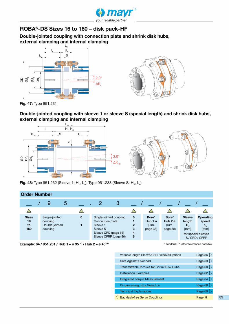
L2
l1
ØD
Ød 2
Ød 3
S
U1
Ød S
k
L4, L6
l1
Ød 2
Ød S
S
H1, HS
h 1
U
ØD
k
your reliable partner
Double-jointed coupling with sleeve 1 or sleeve S (special length) and shrink disk hubs, external clamping and internal clamping
Fig. 48: Type 951.232 (Sleeve 1: H1, L4), Type 951.233 (Sleeve S: HS, L6)
Double-jointed coupling with connection plate and shrink disk hubs, external clamping and internal clamping
Fig. 47: Type 951.231
ROBA®-DS Sizes 16 to 160 – disk pack-HF
2,0°
∆Kr
2,0°
∆Kr H
Variable length Sleeve/CFRP sleeve/Options Page 56
Safe Against Overload Page 59
Transmittable Torques for Shrink Disk Hubs Page 60
Installation Examples Page 62
Integrated Torque Measurement Page 64
Dimensioning, Size Selection Page 68
Technical Explanations Page 69
Backlash-free Servo Couplings Page 8
Order Number
__ / 9 5 __ . 2 3 __ / __ / __ / __ / __
Sizes 16 to
160
Single-jointed coupling Double-jointedcoupling
0 1
Single-jointed coupling Connection plate Sleeve 1 Sleeve SSleeve CRD (page 56)Sleeve CFRP (page 56)
0 1 2 345
Bore* Hub 1 ø
(Dim. page 38)
Bore* Hub 2 ø
(Dim. page 38)
Sleeve length
HS
[mm]
Operating speed
nS
[rpm]
for special sleeves S / CRD / CFRP
Example: 64 / 951.231 / Hub 1 – ø 35 H7 / Hub 2 – ø 40 H7 *Standard H7, other tolerances possible
39

Ll4U
ØD
Ød 5
Ød S
G Ød LP
Sk
your reliable partner
Fig. 49: Type 950.990
Single-jointed coupling with shrink disk hubs, large
Size 16 25 40 64 100 160d3 33 41 46 51 66 76d5 77 82 100 115 143 162dH1 43 54 62 71 92 98dLP 45 55 65 74 88 103H1 70 80 96 116 136 140HS acc. customer specificationsh1 50 60 70 80 100 110k 3,5 3,5 3,5 4 5,5 5,5L 87,1 97,2 108,4 119,6 130 151,6L2 106,2 116,4 130,8 147,2 158 185,2L4 150 170 196 226 256 280L6 dependent on HS
l4 40 45 50 55 60 70S 7,1 7,2 8,4 9,6 10 11,6U 7 7 8 10 10 12U1 26,2 26,4 30,8 37,2 38 45,2
Dimensions [mm] Mass Moments of Inertia J [10-3 kgm2]
Weight [kg]
Size 16 25 40 64 100 160
Disk pack 8) 0,08 0,12 0,26 0,74 1,19 3,27
Hub 9) 0,78 1,23 2,88 5,81 13,77 27,35
Connection plate 0,23 0,44 0,95 2,30 4,60 9,72
Sleeve 1 0,32 0,61 1,38 3,02 6,10 12,96Sleeve S withHS = 1000 mm
2,11 3,77 7,81 12,62 24,98 49,43
Sleeve S per1000 mm tube
1,93 3,43 7,12 10,86 21,86 41,61
Size 16 25 40 64 100 160
Disk pack 8) 0,08 0,09 0,15 0,29 0,35 0,67
Hub 9) 0,79 1,02 1,71 2,53 3,92 6,08
Connection plate 0,31 0,43 0,68 1,19 1,96 2,96
Sleeve 1 0,39 0,54 0,93 1,46 2,04 3,38Sleeve S withHS = 1000 mm
3,63 4,42 6,82 8,09 10,22 16,83
Sleeve S per1000 mm tube
3,48 4,22 6,51 7,50 9,47 15,34
ROBA®-DS Sizes 16 to 160 – disk pack-HF
Technical Data and Main DimensionsSize
16 25 40 64 100 160Nominal torque 1) TKN [Nm] 190 290 450 720 1000 1600
Peak torque 2) TKS [Nm] 285 435 675 1080 1500 2400
Outer diameter D [mm] 77 89 104 123 143 167
Minimum hub bore dSG min [mm] 25 32 40 45 55 65
Maximum hub bore dSG max [mm] 45 52 60 70 90 100
Maximum speed 3) nmax [rpm] 13600 11800 10100 8500 7300 6200
Permittedmisalignments 4)
permitted axial displacement 5) 6) ∆Ka [mm] 1,1 1,3 1,5 1,8 2,1 2,5
permitted radial misalignment 5)
with connection plate ∆Kr [mm] 0,3 0,3 0,4 0,45 0,45 0,55
with sleeve 1 ∆Kr H [mm] 1,0 1,2 1,5 1,8 2,1 2,2
with sleeve S ∆Kr H [mm] (HS - S) x 0,0174
Spring rigidity
torsion 10) disk pack CT LP [103 Nm/rad] 145 280 301 748 1135 1920
tube sleeve S CT H rel. [106 Nm mm/rad] 19 34 71 108 217 415
angular spring rigidity 7) [Nm/rad] 229 248 298 876 1089 1990
1,0°
1 CT tot. = 2 HS [mm] - 2 S [mm]
CT LP CT H rel.
1) Valid for changing load direction as well as for max. permitted shaft misalignment.
2) Valid for unchanging load direction, max. load cycles ≤ 105.3) Not valid for coupling with sleeve S.4) The permitted misalignments may not simultaneously
reach their maximum values.5) The values refer to couplings with 2 disk packs.6) Only permitted as a static or virtually static value.7) The values refer to 1 disk pack. 8) Mass moments of inertia and weights are valid for 1 disk pack.
9) Mass moments of inertia and weights are valid for maximum bore.10) The CT-value of a
double-jointed coupling can be roughly calculated as follows:40

L2
l4
Ød 5
Ød S
G
Ød 3 Ø
d LP
S
U1
ØD
k
L4, L6
l4
Ød 5
Ød S
G
S
H1, HS
h 1
U
ØD
k
Ød LP
Ød H
1
your reliable partner
Double-jointed coupling with sleeve 1 or sleeve S (special length) and shrink disk hubs, large
Fig. 51: Type 951.992 (Sleeve 1: H1, L4), Type 951.993 (Sleeve S: HS, L6)
Double-jointed coupling with connection plate and shrink disk hubs, large
Fig. 50: Type 951.991
ROBA®-DS Sizes 16 to 160 – disk pack-HF
2,0°
∆Kr
2,0°
∆Kr H
Variable length Sleeve S/CFRP sleeve/Options Page 56
Safe Against Overload Page 59
Installation Examples Page 62
Integrated Torque Measurement Page 64
Dimensioning, Size Selection Page 68
Technical Explanations Page 69
Backlash-free Servo Couplings Page 8
Order Number
__ / 9 5 __ . 9 9 __ / __ / __ / __ / __
Sizes 16 to
160
Single-jointed coupling Double-jointedcoupling
0 1
Single-jointed coupling Connection plate Sleeve 1 Sleeve SSleeve CRD (page 56)Sleeve CFRP (page 56)
0 1 2 345
Bore* Hub 1 ø
(Dim. page 40)
Bore* Hub 2 ø
(Dim. page 40)
Sleeve length
HS
[mm]
Operating speed
nS
[rpm]
for special sleeves S / CRD / CFRP
Example: 16 / 951.991 / Hub 1 – ø 35 H7 / Hub 2 – ø 35 H7 *Standard H7, other tolerances possible
41

U
ØD
Ød
Ød 3
Ød H
S
L2
U1
l
l3
ØDSK
your reliable partner
Fig. 52: Type 951.881
Size 16 25 40 64 100 160
DSK 55 67 76 87 108 122d 50 60 70 80 100 115d3 33 41 46 51 66 76H1 70 80 96 116 136 140HS acc. customer specificationsh1 50 60 70 80 100 110L2 106,2 116,4 140,8 167,2 188 215,2L4 150 170 206 246 286 310L6 dependent on HS
l 40 45 55 65 75 85l3 31 35 43 51 61 69lA 25,7 30,8 40 51,2 56,6 58,6S 7,1 7,2 8,4 9,6 10 11,6U 7 7 8 10 10 12U1 26,2 26,4 30,8 37,2 38 45,2
Dimensions [mm] Mass Moments of Inertia J [10-3 kgm2]
Weight [kg]
Size 16 25 40 64 100 160
Disk pack 9) 0,08 0,12 0,26 0,74 1,19 3,27
Hub 10) 0,25 0,54 1,20 2,63 6,31 12,49
Connection plate 0,23 0,44 0,95 2,30 4,60 9,72
Sleeve 1 0,32 0,61 1,38 3,02 6,10 12,96Sleeve S withHS = 1000 mm
2,11 3,77 7,81 12,62 24,98 49,43
Sleeve S per1000 mm tube
1,93 3,43 7,12 10,86 21,86 41,61
Size 16 25 40 64 100 160
Disk pack 9) 0,08 0,09 0,15 0,29 0,35 0,67
Hub 10) 0,47 0,76 1,21 1,96 3,17 4,45
Connection plate 0,31 0,43 0,68 1,19 1,96 2,96
Sleeve 1 0,39 0,54 0,93 1,46 2,04 3,38Sleeve S withHS = 1000 mm 3,63 4,42 6,82 8,09 10,22 16,83
Sleeve S per1000 mm tube
3,48 4,22 6,51 7,50 9,47 15,34
ROBA®-DS Sizes 16 to 160 – disk pack-HF
Optional keyway design according to DIN 6885 possible
Technical Data and Main DimensionsSize
16 25 40 64 100 160Nominal torque 1) TKN [Nm] 190 290 450 720 1000 1600
Peak torque 2) TKS [Nm] 285 435 675 1080 1500 2400
Outer diameter D [mm] 77 89 104 123 143 167
Minimum hub bore 3) dH min [mm] 18 22 25 30 35 40
Maximum hub bore 3) dH max [mm] 28 32 40 45 60 75
Maximum speed 4) nmax [rpm] 9500 8200 7000 6000 5100 4300
Permittedmisalignments 5)
permitted axial displacement 6) 7) ∆Ka [mm] 1,1 1,3 1,5 1,8 2,1 2,5
permitted radial misalignment 6)
with connection plate ∆Kr [mm] 0,3 0,3 0,4 0,45 0,45 0,55
with sleeve 1 ∆Kr H [mm] 1,0 1,2 1,5 1,8 2,1 2,2
with sleeve S ∆Kr H [mm] (HS - S) x 0,0174
Spring rigidity
torsion 11) disk pack CT LP [103 Nm/rad] 145 280 301 748 1135 1920
tube sleeve S CT H rel. [106 Nm mm/rad] 19 34 71 108 217 415
angular spring rigidity 8) [Nm/rad] 229 248 298 876 1089 1990
1) Valid for unchanging load direction as well as for max. permitted shaft misalignment. When the load direction changes, max. 60% of the stated nominal torque is permitted.
2) Valid for unchanging load direction, max. load cycles ≤ 105.3) Transmittable torques dependent on bore, see page 60.4) Not valid for coupling with sleeve S.5) The permitted misalignments may not simultaneously reach their
maximum values.6) The values refer to couplings with 2 disk packs.7) Only permitted as a static or virtually static value.8) The values refer to 1 disk pack. 9) Mass moments of inertia and weights are valid for 1 disk pack.
10) Mass moments of inertia and weights are valid for maximum bore. 11) The CT-value of a
double-jointed coupling can be roughly calculated as follows:
2,0°
∆Kr
1 CT tot. = 2 HS [mm] - 2 S [mm]
CT LP CT H rel.
Double-jointed coupling with connection plate and split clamping hub
rotation circle diameter ØDSK of the clamping screws
42

L4, L6
l
Ød
Ød H
S
H1, HS
h 1
U
ØD
l3
lA
your reliable partner
Double-jointed coupling with sleeve 1 or sleeve S (special length) and split clamping hubs
Fig. 53: Type 951.882 (Sleeve 1: H1, L4), Type 951.883 (Sleeve S: HS, L6)
ROBA®-DS Sizes 16 to 160 – disk pack-HF
Optional keyway design according to DIN 6885 possible
2,0°
∆Kr H
Variable length Sleeve/CFRP sleeve/Options Page 56
Safe Against Overload Page 59
Transmittable Torques for Split Clamping Hubs Page 60
Installation Examples Page 62
Integrated Torque Measurement Page 64
Dimensioning, Size Selection Page 68
Technical Explanations Page 69
Backlash-free Servo Couplings Page 8
Fig. 54: Axial displacement of the half-shells during radial assembly/disassembly (only necessary on Type 951.881).
Installation coupling with split clamping hubs
Order Number
__ / 9 5 1 . 8 8 __ / __ / __ / __ / __
Sizes 16 to
160
Connection plate Sleeve 1 Sleeve SSleeve CRD (page 56)Sleeve CFRP (page 56)
1 2 345
Bore* Hub 1 ø
(Dim. page 42)
Bore* Hub 2 ø
(Dim. page 42)
Sleeve length
HS
[mm]
Operating speed
nS
[rpm]
for special sleeves S / CRD / CFRP
Example: 100 / 951.881 / Hub 1 – ø 50 H7 / Hub 2 – ø 50 H7 *Standard H7, other tolerances possible
43

LU2
ØD
ØZ
Ød 4
Sf
a
ØT K
your reliable partner
Fig. 55: Type 950.660
Single-jointed coupling with flanges
Size 16 25 40 64 100 160
a 6 x M8 6 x M8 6 x M10 6 x M10 6 x M12 6 x M14
d3 33 41 46 51 66 76
d4 40 50 60 70 85 100
f 4 4 4 5 5 5
H1 70 80 96 116 136 140
HS acc. customer specifications
h1 50 60 70 80 100 110
L 37,1 37,2 44,4 49,6 50 68,6
L2 56,2 56,4 66,8 77,2 78 102,2
L4 100 110 132 156 176 197
L6 dependent on HS
S 7,1 7,2 8,4 9,6 10 11,6
TK 62 75 86 103 116 140
U 7 7 8 10 10 12
U1 26,2 26,4 30,8 37,2 38 45,2
U2 15 15 18 20 20 28,5
Dimensions [mm] Mass Moments of Inertia J [10-3 kgm2]
Weight [kg]
Size 16 25 40 64 100 160
Disk pack 9) 0,08 0,12 0,26 0,74 1,19 3,27
Flange 0,23 0,43 0,89 1,95 3,87 9,48
Connection plate 0,23 0,44 0,95 2,30 4,60 9,72
Sleeve 1 0,32 0,61 1,38 3,02 6,10 12,96Sleeve S withHS = 1000 mm
2,11 3,77 7,81 12,62 24,98 49,43
Sleeve S per1000 mm tube
1,93 3,43 7,12 10,86 21,86 41,61
Size 16 25 40 64 100 160
Disk pack 9) 0,08 0,09 0,15 0,29 0,35 0,67
Flange 0,26 0,34 0,52 0,82 1,16 2,10
Connection plate 0,31 0,43 0,68 1,19 1,96 2,96
Sleeve 1 0,39 0,54 0,93 1,46 2,04 3,38Sleeve S withHS = 1000 mm
3,63 4,42 6,82 8,09 10,22 16,83
Sleeve S per1000 mm tube
3,48 4,22 6,51 7,50 9,47 15,34
Technical Data and Main DimensionsSize
16 25 40 64 100 160Nominal torque 1) TKN [Nm] 190 290 450 720 1000 1600
Peak torque 2) TKS [Nm] 285 435 675 1080 1500 2400
Outer diameter D [mm] 77 89 104 123 143 167
Centering bore ZH7 [mm] 45 55 65 75 92 105
Maximum speed 3) nmax [rpm] 13600 11800 10100 8500 7300 6200
Permittedmisalignments 4)
permitted axial displacement 5) 6) ∆Ka [mm] 1,1 1,3 1,5 1,8 2,1 2,5
permitted radial misalignment 5)
with connection plate ∆Kr [mm] 0,3 0,3 0,4 0,45 0,45 0,55
with sleeve 1 ∆Kr H [mm] 1,0 1,2 1,5 1,8 2,1 2,2
with sleeve S ∆Kr H [mm] (HS - S) x 0,0174
Springrigidity
torsion 7) disk pack CT LP [103 Nm/rad] 145 280 301 748 1135 1920
tube sleeve S CT H rel. [106 Nm mm/rad] 19 34 71 108 217 415
angular spring rigidity 8) [Nm/rad] 229 248 298 876 1089 1990
1) Valid for changing load direction as well as for max. permitted shaft misalignment.
2) Valid for unchanging load direction, max. load cycles ≤ 105.3) Not valid for coupling with sleeve S.4) The permitted misalignments may not simultaneously
reach their maximum values.5) The values refer to couplings with 2 disk packs.6) Only permitted as a static or virtually static value.
7) The CT-value of a double-jointed coupling
can be roughly calculated as follows:
8) The values refer to 1 disk pack.9) Mass moments of inertia and weights are valid for 1 disk pack.
ROBA®-DS Sizes 16 to 160 – disk pack-HF
1,0°
1 CT tot. = 2 HS [mm] - 2 S [mm]
CT LP CT H rel.
44

L2
U2
ØD
ØZ
Ød 4
Sf
a
ØT K
U1
Ød 3
L4, L6
U2
ØD
ØZ
Ød 4
Sf
a
ØT K
H1, HS
h 1
your reliable partner
Double-jointed coupling with sleeve 1 or sleeve S (special length) and flanges
Fig. 57: Type 951.662 (Sleeve 1: H1, L4), Type 951.663 (Sleeve S: HS, L6)
Double-jointed coupling with connection plate and flanges
Fig. 56: Type 951.661
ROBA®-DS Sizes 16 to 160 – disk pack-HF
2,0°
∆Kr
2,0°
∆Kr H
Variable length Sleeve S/CFRP sleeve/Options Page 56
Safe Against Overload Page 59
Installation Examples Page 62
Integrated Torque Measurement Page 64
Dimensioning, Size Selection Page 68
Technical Explanations Page 69
Backlash-free Servo Couplings Page 8
Order Number
__ / 9 5 __ . 6 6 __ / __ / __
Sizes 16 to
160
Single-jointed coupling Double-jointedcoupling
0 1
Single-jointed coupling Connection plate Sleeve 1 Sleeve SSleeve CRD (page 56)Sleeve CFRP (page 56)
0 1 2 345
Sleeve length
HS
[mm]
Operating speed
nS
[rpm]
for special sleeves S / CRD / CFRP
Example: 40 / 951.661
45

Ll
U
ØD
Ød 1
Ød p
S
your reliable partner
Fig. 58: Type 950.000
Single-jointed coupling with key hubs
ROBA®-DS Sizes 180 to 2200
Technical Data and Main DimensionsSize
180 300 500 850 1400 2200Nominal torque 1) TKN [Nm] 2100 3500 5800 9500 15000 24000
Peak torque 2) TKS [Nm] 3150 5250 8700 14250 22500 36000
Outer diameter D [mm] 143 167 198 234 274 314
Minimum hub bore 3) dp min [mm] 40 45 55 65 75 90
Maximum hub bore 3) dp max [mm] 75 90 105 120 140 170
Maximum speed 4) nmax [rpm] 7300 6200 5200 4400 3800 3300
Permittedmisalignments 5)
permitted axial displacement 6) 7) ∆Ka [mm] 1,0 1,2 1,4 1,6 1,9 2,2
permitted radialmisalignment 6)
with connection plate ∆Kr [mm] 0,25 0,25 0,35 0,4 0,5 0,55
with sleeve 1 ∆Kr H [mm] 1,2 1,25 1,35 1,7 2 2,6
with sleeve S ∆Kr H [mm] (HS - S) x 0,00873
Spring rigidity
torsion 11)disk pack CT LP [103 Nm/rad] 3000 3480 11900 20600 30150 46800
tube sleeve S CT H rel. [106 Nm mm/rad] 250 415 894 1690 2734 4961
angular spring rigidity 8) [Nm/rad] 3890 6980 11250 18580 26120 28520
Size 180 300 500 850 1400 2200d1 104 121 141 164 190 230d3 54 61 66 76 86 110
dpi min 40 45 55 65 75 90dpi max 55 70 85 95 110 130
H1 150 160 170 220 266 320HS acc. customer specificationsh1 92,5 111 132 150 174 206hS 92 110 130 150 165 190L 181,2 191,2 212 264 316 377,8L1 178 192 206 260 310 370L2 212,4 224,4 252 315 374 443,6L4 320 340 370 470 566 680L6 dependent on HS
l 85 90 100 125 150 180S 11,2 11,2 12 14 16 17,8U 14 16 18 20 22 25U1 42,4 44,4 52 65 74 83,6
Dimensions [mm] Mass Moments of Inertia J [10-3 kgm2]Size 180 300 500 850 1400 2200
Disk pack 9) 2,64 5,60 14,58 36,85 83,86 132,19
Hub key 10) 6,45 13,14 28,21 63,01 134,49 323,57
Hub key: internal 10) 4,26 9,18 20,64 46,85 95,76 207,12
Connection plate 3,91 8,60 21,54 53,27 114,26 241,16
Sleeve 1 6,85 14,22 29,94 67,40 149,09 341,78Sleeve Swith HS = 1000 mm
28,41 51,24 109,74 210,27 364,62 705,89
Sleeve Sper 1000 mm tube
25,08 41,61 89,57 169,22 273,78 496,68
Weight [kg]Size 180 300 500 850 1400 2200
Disk pack 9) 0,73 1,15 2,14 3,92 6,52 7,51
Hub key 10) 2,80 4,01 6,25 10,51 16,62 28,46
Hub key: internal 10) 2,38 3,32 5,36 9,00 14,44 23,26
Connection plate 1,53 2,44 4,48 8,04 12,64 19,55
Sleeve 1 2,61 3,66 5,38 9,32 15,62 26,98Sleeve Swith HS = 1000 mm
14,37 17,45 27,01 38,66 53,84 77,23
Sleeve Sper 1000 mm tube
13,64 15,34 23,97 34,36 46,78 64,41
1) Valid for changing load direction as well as for max. permitted shaft misalignment.
2) Valid for unchanging load direction, max. load cycles ≤ 105.3) Transmittable torques dependent on bore, see page 61.4) Not valid for coupling with sleeve S.5) The permitted misalignments may not simultaneously
reach their maximum values.6) The values refer to couplings with 2 disk packs.7) Only permitted as a static or virtually static value.8) The values refer to 1 disk pack.
9) Mass moments of inertia and weights are valid for 1 disk pack.10) Mass moments of inertia and weights are valid for maximum bore.11) The CT-value of a double-jointed coupling can be roughly calculated as follows:
1 CT tot. = 2 HS [mm] - 2 S [mm]
CT LP CT H rel.
0,5°
46

L2
lU
ØD
Ød 1
Ød p
Ød 3
S
U1
L4, L6
lU
ØD
Ød 1
Ød p
SU
H1, HS
h 1, h
S
L1
U
ØD
Ød pi
S
U
H1
h 1
your reliable partner
Double-jointed coupling with sleeve 1 or sleeve S (special length) and key hubs
Fig. 60: Type 951.002 (Sleeve 1: H1, h1, L4), Type 951.003 (Sleeve S: HS, hS, L6)
Double-jointed coupling with connection plate and key hubs
Fig. 59: Type 951.001
ROBA®-DS Sizes 180 to 2200
Fig. 61: Type 951.772 (Sleeve 1: H1, L1)
1,0°
∆Kr
1,0°
∆Kr H
Variable length Sleeve S/CFRP sleeve/Options Page 56
Safe Against Overload Page 59
Transmittable Torques for Key Hubs Page 61
Installation Examples Page 62
Integrated Torque Measurement Page 64
Dimensioning, Size Selection Page 68
Technical Explanations Page 69
Backlash-free Servo Couplings Page 8
1,0°∆Kr H
Double-jointed coupling with sleeve 1 and key hubs (internal/internal)
Order Number
HUB 1 HUB 2Key hub Standard Key hub internal (Fig. 61)
0 7
0 7
Key hub StandardKey hub internal (Fig. 61)
__ / 9 5 __ . __ __ __ / __ / __ / __ / __
Sizes 180 to
2200
Single-jointed coupling Double-jointedcoupling
0 1
Single-jointed coupling Connection plate Sleeve 1 Sleeve SSleeve CRD (page 56)Sleeve CFRP (page 56)
0 1 2 345
Bore* Hub 1 ø
(Dim. page 46)
Bore* Hub 2 ø
(Dim. page 46)
Sleeve length
HS
[mm]
Operating speed
nS
[rpm]for special sleeves
S / CRD / CFRP
Example: 300 / 951.001 / Hub 1 – ø 50 H7 / Hub 2 – ø 60 H7 *Standard H7, other tolerances possible
47
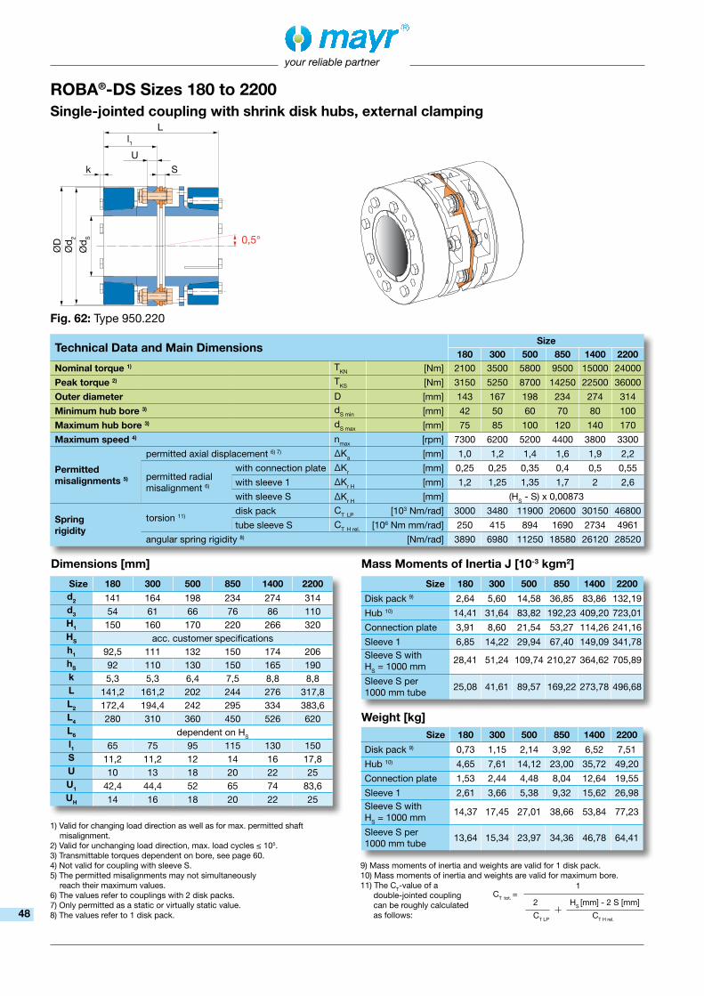
Ll1U
ØD
Ød 2
Ød S
Sk
your reliable partner
Fig. 62: Type 950.220
Single-jointed coupling with shrink disk hubs, external clamping
Size 180 300 500 850 1400 2200d2 141 164 198 234 274 314d3 54 61 66 76 86 110H1 150 160 170 220 266 320HS acc. customer specificationsh1 92,5 111 132 150 174 206hS 92 110 130 150 165 190k 5,3 5,3 6,4 7,5 8,8 8,8L 141,2 161,2 202 244 276 317,8L2 172,4 194,4 242 295 334 383,6L4 280 310 360 450 526 620L6 dependent on HS
l1 65 75 95 115 130 150S 11,2 11,2 12 14 16 17,8U 10 13 18 20 22 25U1 42,4 44,4 52 65 74 83,6UH 14 16 18 20 22 25
Dimensions [mm] Mass Moments of Inertia J [10-3 kgm2]
Weight [kg]
Size 180 300 500 850 1400 2200
Disk pack 9) 2,64 5,60 14,58 36,85 83,86 132,19
Hub 10) 14,41 31,64 83,82 192,23 409,20 723,01
Connection plate 3,91 8,60 21,54 53,27 114,26 241,16
Sleeve 1 6,85 14,22 29,94 67,40 149,09 341,78Sleeve S withHS = 1000 mm
28,41 51,24 109,74 210,27 364,62 705,89
Sleeve S per1000 mm tube
25,08 41,61 89,57 169,22 273,78 496,68
Size 180 300 500 850 1400 2200
Disk pack 9) 0,73 1,15 2,14 3,92 6,52 7,51
Hub 10) 4,65 7,61 14,12 23,00 35,72 49,20
Connection plate 1,53 2,44 4,48 8,04 12,64 19,55
Sleeve 1 2,61 3,66 5,38 9,32 15,62 26,98Sleeve S withHS = 1000 mm
14,37 17,45 27,01 38,66 53,84 77,23
Sleeve S per1000 mm tube
13,64 15,34 23,97 34,36 46,78 64,41
Technical Data and Main DimensionsSize
180 300 500 850 1400 2200Nominal torque 1) TKN [Nm] 2100 3500 5800 9500 15000 24000
Peak torque 2) TKS [Nm] 3150 5250 8700 14250 22500 36000
Outer diameter D [mm] 143 167 198 234 274 314
Minimum hub bore 3) dS min [mm] 42 50 60 70 80 100
Maximum hub bore 3) dS max [mm] 75 85 100 120 140 170
Maximum speed 4) nmax [rpm] 7300 6200 5200 4400 3800 3300
Permittedmisalignments 5)
permitted axial displacement 6) 7) ∆Ka [mm] 1,0 1,2 1,4 1,6 1,9 2,2
permitted radial misalignment 6)
with connection plate ∆Kr [mm] 0,25 0,25 0,35 0,4 0,5 0,55
with sleeve 1 ∆Kr H [mm] 1,2 1,25 1,35 1,7 2 2,6
with sleeve S ∆Kr H [mm] (HS - S) x 0,00873
Spring rigidity
torsion 11) disk pack CT LP [103 Nm/rad] 3000 3480 11900 20600 30150 46800
tube sleeve S CT H rel. [106 Nm mm/rad] 250 415 894 1690 2734 4961
angular spring rigidity 8) [Nm/rad] 3890 6980 11250 18580 26120 28520
ROBA®-DS Sizes 180 to 2200
1) Valid for changing load direction as well as for max. permitted shaft misalignment.
2) Valid for unchanging load direction, max. load cycles ≤ 105.3) Transmittable torques dependent on bore, see page 60.4) Not valid for coupling with sleeve S.5) The permitted misalignments may not simultaneously
reach their maximum values.6) The values refer to couplings with 2 disk packs.7) Only permitted as a static or virtually static value.8) The values refer to 1 disk pack.
9) Mass moments of inertia and weights are valid for 1 disk pack.10) Mass moments of inertia and weights are valid for maximum bore.11) The CT-value of a double-jointed coupling can be roughly calculated as follows:
0,5°
1 CT tot. = 2 HS [mm] - 2 S [mm]
CT LP CT H rel.48

l2
p
Ød w
ØD
3
l
U
L2
l1
Ød 2
Ød S
Ød 3
S
U1
ØD
k
L4, L6
l1
Ød 2
Ød S
S
H1, HS
h 1, h
S
UH
ØD
k
your reliable partner
Double-jointed coupling with sleeve 1 or sleeve S (special length) and shrink disk hubs, external clamping
Fig. 64: Type 951.222 (Sleeve 1: H1, h1, L4), Type 951.223 (Sleeve S: HS, hS, L6)
Double-jointed coupling with connection plate and shrink disk hubs, external clamping
Fig. 63: Type 951.221
ROBA®-DS Sizes 180 to 2200
Additional Option: External shrink disk hub
Size dw D3 l l2 p
180 65/70 145 85 39 -
300 75/80 170 90 50 -
500 80/85 185 100 57 -
850 95/100/105 230 125 82 4
1400 110/115 265 150 88 -
2200 130/135 300 180 98 -
1,0°
∆Kr
1,0°
∆Kr H
Variable length Sleeve/CFRP sleeve/Options Page 56
Safe Against Overload Page 59
Transmittable Torques for Shrink Disk Hubs Page 60
Installation Examples Page 62
Integrated Torque Measurement Page 64
Dimensioning, Size Selection Page 68
Technical Explanations Page 69
Backlash-free Servo Couplings Page 8
Order Number
__ / 9 5 __ . 2 2 __ / __ / __ / __ / __
Sizes 180 to
2200
Single-jointed coupling Double-jointedcoupling
0 1
Single-jointed coupling Connection plate Sleeve 1 Sleeve SSleeve CRD (page 56)Sleeve CFRP (page 56)
0 1 2 345
Bore* Hub 1 ø
(Dim. page 48)
Bore* Hub 2 ø
(Dim. page 48)
Sleeve length
HS
[mm]
Operating speed
nS
[rpm]
for special sleeves S / CRD / CFRP
Example: 100 / 951.221 / Hub 1 – ø 45 H7 / Hub 2 – ø 45 H7 *Standard H7, other tolerances possible
49

U
ØD
Ød
Ød H
Ød 3
S
L2
U1
l
l3
lA
ØDSK
your reliable partner
Double-jointed coupling with connection plate and split clamping hub
Fig. 65: Type 951.881
Size 180 300 500 850 1400 2200DSK 107 128 150 173 200 -d 102 121 141 164 190 230d3 54 61 66 76 86 110H1 150 160 170 220 266 320HS acc. customer specificationsh1 92,5 111 132 150 174 206hS 92 110 130 150 165 190L2 212,4 224,4 252 315 374 443,6L4 320 340 370 470 566 680L6 dependent on HS
l 85 90 100 125 150 180l3 68 70 77 97 117 147lA 58,7 58,7 65,1 83,2 100,6 127,3lB 64,6 66,5 72 92,5 113 140S 11,2 11,2 12 14 16 17,8U 14 16 18 20 22 25U1 42,4 44,4 52 65 74 83,6
Dimensions [mm] Mass Moments of Inertia J [10-3 kgm2]
Weight [kg]
Size 180 300 500 850 1400 2200
Disk pack 9) 2,64 5,60 14,58 36,85 83,86 132,19
Hub 10) 6,61 14,02 30,01 65,69 146,71 352,20
Connection plate 3,91 8,60 21,54 53,27 114,26 241,16
Sleeve 1 6,85 14,22 29,94 67,40 149,09 341,78Sleeve S withHS = 1000 mm
28,41 51,24 109,74 210,27 364,62 705,89
Sleeve S per1000 mm tube
25,08 41,61 89,57 169,22 273,78 496,68
Size 180 300 500 850 1400 2200
Disk pack 9) 0,73 1,15 2,14 3,92 6,52 7,51
Hub 10) 3,19 4,66 7,20 11,70 20,26 33,95
Connection plate 1,53 2,44 4,48 8,04 12,64 19,55
Sleeve 1 2,61 3,66 5,38 9,32 15,62 26,98Sleeve S withHS = 1000 mm
14,37 17,45 27,01 38,66 53,84 77,23
Sleeve S per1000 mm tube
13,64 15,34 23,97 34,36 46,78 64,41
ROBA®-DS Sizes 180 to 2200
Only available with keyway acc. DIN 6885!
Technical Data and Main DimensionsSize
180 300 500 850 1400 2200Nominal torque 1) TKN [Nm] 2100 3500 5800 9500 15000 24000
Peak torque 2) TKS [Nm] 3150 5250 8700 14250 22500 36000
Outer diameter D [mm] 143 167 198 234 274 314
Minimum hub bore dH min [mm] 42 50 60 70 80 100
Maximum hub bore dH max [mm] 65 80 95 110 120 150
Maximum speed 3) nmax [rpm] 5100 4300 3600 3100 2600 2300
Permittedmisalignments 4)
permitted axial displacement 6) 7) ∆Ka [mm] 1,0 1,2 1,4 1,6 1,9 2,2
permitted radial misalignment 6)
with connection plate ∆Kr [mm] 0,25 0,25 0,35 0,4 0,5 0,55
with sleeve 1 ∆Kr H [mm] 1,2 1,25 1,35 1,7 2 2,6
with sleeve S ∆Kr H [mm] (HS - S) x 0,00873
Spring rigidity
torsion 5) disk pack CT LP [103 Nm/rad] 3000 3480 11900 20600 30150 46800
tube sleeve S CT H rel. [106 Nm mm/rad] 250 415 894 1690 2734 4961
angular spring rigidity 8) [Nm/rad] 3890 6980 11250 18580 26120 28520
1) Valid for unchanging load direction as well as for max. permitted shaft misalignment.
2) Valid for unchanging load direction, max. load cycles ≤ 105.3) Not valid for coupling with sleeve S.4) The permitted misalignments may not simultaneously reach their
maximum values.5) The CT-value of a double-
jointed coupling can be roughly calculated as follows:
6) The values refer to couplings with 2 disk packs.7) Only permitted as a static or virtually static value.8) The values refer to 1 disk pack.9) Mass moments of inertia and weights are valid for 1 disk pack.10) Mass moments of inertia and weights are valid for maximum bore.
1,0°
∆Kr
1 CT tot. = 2 HS [mm] - 2 S [mm]
CT LP CT H rel.
rotation circle diameter ØDSK of the clamping screws
50

L4, L6
ll3
Ød
Ød H
S
H1, HS
h 1, h
S
U
ØD
lB
your reliable partner
Double-jointed coupling with sleeve 1 or sleeve S (special length) and split clamping hubs
Fig. 66: Type 951.882 (Sleeve 1: H1, h1, L4) Type 951.883 (Sleeve S: HS, hS, L6)
ROBA®-DS Sizes 180 to 2200
Only available with keyway acc. DIN 6885!
1,0°
∆Kr H
Variable length Sleeve S/CFRP sleeve/Options Page 56
Safe Against Overload Page 59
Installation Examples Page 62
Integrated Torque Measurement Page 64
Dimensioning, Size Selection Page 68
Technical Explanations Page 69
Backlash-free Servo Couplings Page 8
Fig. 67: Axial displacement of the half-shells during radial assembly/disassembly Please observe dimensions lA and lB!
Installation coupling with split clamping hubs
Order Number
__ / 9 5 1 . 8 8 __ / __ / __ / __ / __
Sizes 180 to
2200
Connection plate Sleeve 1 Sleeve SSleeve CRD (page 56)Sleeve CFRP (page 56)
1 2 345
Bore* Hub 1 ø
(Dim. page 50)
Bore* Hub 2 ø
(Dim. page 50)
Sleeve length
HS
[mm]
Operating speed
nS
[rpm]
for special sleeves S / CRD / CFRP
Example: 100 / 951.881 / Hub 1 – ø 50 H7 / Hub 2 – ø 50 H7 *Standard H7, other tolerances possible
Only available with keyway acc. DIN 6885! The hubs transmit only 30 – 40 % of the value TKN using frictional locking. Larger torques are transmitted via positive locking with the key.The hubs are not suitable for changing load direction.
51

LU2
ØD
ØZ
Ød 4
Sf
a
ØT K
your reliable partner
Fig. 68: Type 950.660
Single-jointed coupling with flanges
Size 180 300 500 850 1400 2200
a 8 x M12 8 x M16 8 x M16 8 x M20 8 x M24 8 x M30
d3 54 61 66 76 86 110
d4 77 92 112 132 150 170
f 6 6 6 6 6 6
H1 150 160 170 220 266 320
HS acc. customer specifications
h1 92,5 111 132 150 174 206
hS 92 110 130 150 165 190
L 57,2 65,2 84 102 118 129,8
L2 88,4 98,4 124 153 176 195,6
L4 196 214 242 308 368 432
L6 dependent on HS
S 11,2 11,2 12 14 16 17,8
TK 125 150 175 210 240 275
U 14 16 18 20 22 25
U1 42,4 44,4 52 65 74 83,6
U2 23 27 36 44 51 56
Dimensions [mm] Mass Moments of Inertia J [10-3 kgm2]
Weight [kg]
Size 180 300 500 850 1400 2200
Disk pack 9) 2,64 5,60 14,58 36,85 83,86 132,19
Flange 6,26 13,08 34,04 79,39 162,60 359,24
Connection plate 3,91 8,60 21,54 53,27 114,26 241,16
Sleeve 1 6,85 14,22 29,94 67,40 149,09 341,78Sleeve S withHS = 1000 mm
28,41 51,24 109,74 210,27 364,62 705,89
Sleeve S per1000 mm tube
25,08 41,61 89,57 169,22 273,78 496,68
Size 180 300 500 850 1400 2200
Disk pack 9) 0,73 1,15 2,14 3,92 6,52 7,51
Flange 1,70 2,61 4,79 7,88 12,24 20,54
Connection plate 1,53 2,44 4,48 8,04 12,64 19,55
Sleeve 1 2,61 3,66 5,38 9,32 15,62 26,98Sleeve S withHS = 1000 mm
14,37 17,45 27,01 38,66 53,84 77,23
Sleeve S per1000 mm tube
13,64 15,34 23,97 34,36 46,78 64,41
Technical Data and Main DimensionsSize
180 300 500 850 1400 2200Nominal torque 1) TKN [Nm] 2100 3500 5800 9500 15000 24000
Peak torque 2) TKS [Nm] 3150 5250 8700 14250 22500 36000
Outer diameter D [mm] 153 178 210 250 290 336
Centering bore ZH7 [mm] 85 100 120 140 160 180
Maximum speed 3) nmax [rpm] 7300 6200 5200 4400 3800 3300
Permittedmisalignments 4)
permitted axial displacement 5) 6) ∆Ka [mm] 1,0 1,2 1,4 1,6 1,9 2,2
permitted radialmisalignment 5)
with connection plate ∆Kr [mm] 0,25 0,25 0,35 0,4 0,5 0,55
with sleeve 1 ∆Kr H [mm] 1,2 1,25 1,35 1,7 2 2,6
with sleeve S ∆Kr H [mm] (HS - S) x 0,00873
Springrigidity
torsion 7) disk pack CT LP [103 Nm/rad] 3000 3480 11900 20600 30150 46800
tube sleeve S CT H rel. [106 Nm mm/rad] 250 415 894 1690 2734 4961
angular spring rigidity 8) [Nm/rad] 3890 6980 11250 18580 26120 28520
1) Valid for changing load direction as well as for max. permitted shaft misalignment.
2) Valid for unchanging load direction, max. load cycles ≤ 105.3) Not valid for coupling with sleeve S.4) The permitted misalignments may not simultaneously
reach their maximum values.5) The values refer to couplings with 2 disk packs.6) Only permitted as a static or virtually static value.
7) The CT-value of a double-jointed coupling can be roughly calculated as follows:
8) The values refer to 1 disk pack.9) Mass moments of inertia and weights are valid for 1 disk pack.
ROBA®-DS Sizes 180 to 2200
0,5°
1 CT tot. = 2 HS [mm] - 2 S [mm]
CT LP CT H rel.
52

L2
U2
ØD
ØZ
Ød 4
Sf
a
ØT K
U1
Ød 3
L4, L6
U2
ØD
ØZ
Ød 4
Sf
a
ØT K
H1, HS
h 1, h
S
your reliable partner
Double-jointed coupling with sleeve 1 or sleeve S (special length) and flanges
Fig. 70: Type 951.662 (Sleeve 1: H1, h1, L4), Type 951.663 (Sleeve S: HS, hS, L6)
Double-jointed coupling with connection plate and flanges
Fig. 69: Type 951.661
ROBA®-DS Sizes 180 to 2200
1,0°
∆Kr
1,0°
∆Kr H
Variable length Sleeve S/CFRP sleeve/Options Page 56
Safe Against Overload Page 59
Installation Examples Page 62
Integrated Torque Measurement Page 64
Dimensioning, Size Selection Page 68
Technical Explanations Page 69
Backlash-free Servo Couplings Page 8
Order Number
__ / 9 5 __ . 6 6 __ / __ / __
Sizes 180 to
2200
Single-jointed coupling Double-jointedcoupling
0 1
Single-jointed coupling Connection plate Sleeve 1 Sleeve SSleeve CRD (page 56)Sleeve CFRP (page 56)
0 1 2 345
Sleeve length
HS
[mm]
Operating speed
nS
[rpm]
for special sleeves S / CRD / CFRP
Example: 40 / 950.661
53

your reliable partner
ROBA®-DS for high torques - Sizes 2200 to 11000
On the ROBA®-DS with cone connection, the disk pack is connected via positive locking with the hubs, flanges or sleeves. On the outside conical bolts are pulled through tensioning screws into cone-shaped holes on the mounting parts and the collar bushings on the disk packs. The cone shape causes forces to be generated, which widen the collar bushings and mounting parts radially flexibly, thus guaranteeing backlash-free connection of the disk pack.For this backlash-free, positive locking connection, far lower screw tightening torques are required in comparison to standard frictionally locking connections. This makes installation substantially easier. The disk packs and sleeves can be radially installed or de-installed without having to move the respective aggregates.
Cone connection in installed condition De-installation
In installed condition, the cone bolt is pulled through the tensioning screw into the conical bores. In order to de-install the disk pack, the tensioning screw is screwed out and then screwed in with the press cover onto the opposite side of the cone bolt. This loosens the cone bolt and allows it to be pulled back axially. Disk packs and sleeves can be de-installed radially in this way.
Sleeve Disk pack Hub
Cone bolt
Press cover
Tensioning screw
� Low screw tightening torques
� Can be installed / de-installed radially
� Easy and quick installation / de-installation
� No hydraulic installation tools required; can be installed with a torque wrench
� Backlash-free torque transmission
� FEM-optimized disk shape
� High torsional rigidity
� High performance density
� Compensation of axial, angular and radial misalignments
� Wear and maintenance-free
� High flexibility through customer-specific hubs and sleeves
Easy installation and de-installation
ROBA®-DS with cone connection
54

Ød 1
Ød
max
ØD
l S
H
ØD
Ød 1
Ød
max
l
S
your reliable partner
ROBA®-DS for high torques - Sizes 2200 to 11000
Technical Data Size2200 3300 5000 7300 11000
Alternating torque 1) TKW [Nm] 14 700 22 000 33 300 48 700 73 300Nominal torque 2) TKN [Nm] 22 000 33 000 50 000 73 000 110 000Peak torque 3) TKS [Nm] 44 000 66 000 100 000 146 000 220 000Outer diameter D [mm] 290 332 378 431 492Maximum hub bore 6) dmax [mm] 150 170 190 220 250Maximum speed nmax [rpm] 3600 3100 2700 2400 2100
Hubd1 [mm] 186 215 243 279 321l [mm] 175 200 225 265 310
Minimum sleeve length Hmin [mm] 156 166 182 208 223Distance dimension S [mm] 17,8 19 23 24,2 26,5Permitted misalignments 4)
perm. axial displacement 5) ∆Ka [mm] 1,6 1,7 2,1 2,3 2,3perm. radial misalignment with special sleeve ∆Kr H [mm] (H – S) x 6,98 x 10⁻³
perm. angular misalignment ∆Kw [°] 0,4 0,4 0,4 0,4 0,3
Backlash-free shaft-hub connection with a shrink disk is possible.
Single-jointed coupling with key hubs
Double-jointed coupling with sleeve and key hubs
Design example
1) Valid for changing load direction as well as for max. permitted shaft misalignment.
2) Valid for unchanging load direction as well as for max. permitted shaft misalignment.
3) Valid for unchanging load direction, max. load cycles ≤ 105.
4) The permitted misalignments may not simultaneously reach their maximum values.
5) The values refer to couplings with 2 disk packs.
6) Transmittable torques dependent on bore, see page 61.
2 x ∆Kw
∆Kr H
Fig. 72
Fig. 71
Fig. 73
Order Number
__ / 9 5 6 . _____
Size 2200
to 11000
The design of the hubs and sleeves is carried out according to the customer‘s requirements.
Please contact the manufacturer.
Double-jointed coupling with shrink disk hub and flange
Safe Against Overload Page 59
Transmittable Torques for Key Hubs Page 61
Installation Examples Page 62
Dimensioning, Size Selection Page 68
Technical Explanations Page 69
∆Kw
55

h 2
U
d 5
l4
h 3
U
d 5
l4
h S d 4
U
your reliable partner
Variable Sleeve S
Standard design Type 951._ _3 / 953._ _3
Cranked tube (CRD) Type 951._ _4 / 953._ _4
CFRP sleeve Type 951._ _5 / 953._ _5
Fig. 74
Fig. 75
Fig. 76
Variable Length Sleeves (Cardan Shaft Replacement)The operational demands on variable length sleeves vary greatly. Using various sleeve construction shapes, the shaft coupling ROBA®-DS can offer the optimum solution for any problem. The product is able to fulfil the usual demands placed upon conventional cardan shafts. At the same time, the constructional shape all-steel coupling presents decided advantages:
• Backlash-free function
• Completely maintenance-free function
• Suitable for high speeds By replacing conventional disk packs, the coupling misalignment capability can be enlarged by 2 – 3° / compensating level (please contact the manufacturers about availability and Technical Data).
Size 16 25 40 64 100 160 180 300 500 850 1400 2200
d4 43 54 62 71 92 98 79 95 111 127 137 157
d5 45 48 58 68 88 95 75 90 110 123 144 167
hS 50 60 70 80 100 110 92 110 130 150 165 190
h2 x x x x x 155 130 155 170 220 250 x
h3 73 86 96 118 138 160 138 160 192 224 266 315
l4 15,5 15,5 20 24 24 30 32 36 40 48 54 61
U 7 7 8 10 10 12 14 16 18 20 22 25
Dimensions [mm]
Type Identification and Technical Comparison – Variable Length Sleeves
Vertical support special sleeves
Attention!On vertically installed ROBA®-DS couplings with long sleeves, it is necessary to provide a vertical support for absorbing the sleeve‘s own weight.
Selection Aid: Variable Length Sleeves
Type 95_._ _3 95_._ _4 95_._ _5
Speed + ++ +++
Torsional rigidity
++ +++ +
Weight ++ +++ +
Mass moment of inertia
++ +++ +
Corrosion resistance
++ ++ +++
Changes in length due to temperature
+++ +++ +
Costs + ++ +++
Operational focuses
• conventional applications
• medium speeds
• high torsion-al rigidity
• high speeds
• low mass
Fig. 77
+ = low, ++ = medium, +++ = high
x = Technical Data available on demand56

your reliable partner
Safe Against Overload Page 59
Installation Examples Page 62
Integrated Torque Measurement Page 64
Dimensioning, Size Selection Page 68
Technical Explanations Page 69
Backlash-free Servo Couplings Page 8
Backlash-free All-steel Couplings Page 14
CFRP sleeve
ROBA®-DS with CFRP sleeves(Carbon-fibre reinforced plastic)
Sleeves made of CFRP offer unique advantages and open up new application possibilities for torsionally rigid disk pack couplings.
• Up to 80 % lower own weight
• Reduced mass inertia
• High speeds
• Wide bearing distances
• Low thermal expansion
• Corrosion resistance
• Low vibration
• Temperature resistance
Low weightThe lower own weight (up to 80 %) of CFRP material in comparison to steel makes handling and installation much easier and safer.
Reduced inertiaThe reduction in weight is combined with a large reduction in mass inertia. Braking and accelerating procedures are quicker or require lower drive performance.
Higher speedsThe optimum rigidity / weight ratio sets the critical bending speed far higher than with conventional sleeves.
Wide bearing distancesDue to the high critical bending speed, large bearing distances can be bridged without further intermediate bearings being necessary.
Low thermal expansionCFRP sleeves expand approx. 90 % less than steel in response to temperature fluctuations. The disk packs are therefore placed under far less strain, especially when using long sleeves.
Corrosion resistanceAdditional corrosion protection for hubs and sleeve parts ensure a very high corrosion resistance for the entire coupling.
Low vibrationThe far higher self-damping capacity of CFRP material minimises production of vibrations and damps existing vibrations more effectively.
Temperature resistanceCouplings with CFRP sleeves can be used at temperatures of -20 °C up to +80 °C
Fig. 78
57

your reliable partner
ROBA®-DS Options
Options and Variants on Intermediate Shafts
Intermediate shafts
GFRP sleeves
Axial separable sleeves
Poly-cardanic design
Fig. 79
Fig. 80
Fig. 81
Fig. 82
Variable bridges over any shaft distances via adapted steel solid shafts, mounted between two standard hubs.
Please observe the critical bending speeds!
Glass-fibre reinforced plastic sleeves for couplings in leakage current-isolated design.
Fulfils the highest demands on insulation quality (CTI 600).
This design allows radial disassembling of input and output without axial displacement.
Preferred solution on large coupling in connection with inner key hubs
For applications with large axial displacement, e.g. caused by:
• Normal load or overload on the connected system parts
• Ground changes between the foundations
• Temperature differences
• Axial backlash due to wear on the bearing58

your reliable partner
Safe Against Overload
Safe Against Overload Damage
Combination with EAS®-Compact® • Safety clutches in the construction Types Ratchetting, Synchro-nous or Overload
• Flexible adaptation of construction length for connection of shafts with different shaft distances
• Perfectly suited for demands of high torsional rigidity or high speeds
Torque range 5 – 3 000 Nm
Switch-off accuracy ± 5 %
Load disconnecting
Number of overload occurrences high
Time demand for repeat operation start-up 0
Fig. 83 Danger of drive shaft damage no
Combination with EAS®-element coupling • Complete separation of input and output on overload• Particularly suitable for heavy, fast-running drives with large ro-
tating masses• Maximum torsional rigidity at highest performance density
Torque range 250 – 110 000 Nm
Switch-off accuracy ± 5 %
Load disconnecting
Number of overload cases high
Time demand for repeat operation start-up 1 minute
Fig. 84 Danger of drive shaft damage no
Combination with ROBA®-slip hub • Overload protection with load holding function• Compensation of individual dynamic peaks (resonances, start-
up peaks) without operational interruptions• Slip control recommended for protection against thermic
overload
Torque range 2 – 110 000 Nm
Switch-off accuracy ± 20 %
Load holding
Number of overload cases very high
Time demand for repeat operation start-up 0
Fig. 85 Danger of drive shaft damage no
Shrink disk hub with integrated overload protection • Modified shrink disk hub with integrated slip bushing• Suitable for protection against individual, very short dynamic
torque peaks• Not suitable for longer slipping times / high slipping speeds
Torque range 190 – 110 000 Nm
Switch-off accuracy ± 20 % 1)
Load holding
Number of overload cases very low
Time demand for repeat operation start-up
de-installation and installation of coupling
Fig. 86 Danger of drive shaft damage yes
Installation Examples Page 62
Integrated Torque Measurement Page 64
Dimensioning, Size Selection Page 68
Technical Explanations Page 69
1) Tolerance only in limited application conditions – please contact the manufacturer.
Backlash-free Servo Couplings Page 8
Backlash-free All-steel Couplings Page 14
Variable length Sleeve S/CFRP sleeve/Options Page 56 59

your reliable partner
Transmittable Torques
Clamping ring hubs SizeBore 16 25 40 64 100 160
Frictionally-lockingtransmittable torquesClamping ring hubs
Suitable for H7/h6 TR [Nm]
Ø20 126 - - - - -Ø22 138 199 - - - -Ø25 168 226 327 - - -Ø28 201 253 366 523 - -Ø30 216 290 420 561 - -Ø32 230 325 470 598 785 -Ø35 251 355 515 700 859 -Ø38 - 386 559 798 932 -Ø40 - 406 588 840 1050 1256Ø45 - - 661 945 1240 1413Ø50 - - - 1050 1378 1680Ø55 - - - 1155 1516 1940Ø60 - - - 1654 2117Ø65 - 1792 2293Ø68 - 1874 2399Ø70 - - 2470Ø80 - - - - - 2822
Shrink disk hubs SizeBore 16 25 40 64 100 160 180 300 500 850 1400 2200
Frictionally-lockingtransmittable torquesShrink disk hubs
Suitable for H7/g6
TR [Nm]
Ø14 158 - - - - - - - - - - -Ø16 186 - - - - - - - - - - -Ø20 240 283 - - - - - - - - - -Ø22 269 320 - - - - - - - - - -Ø25 312 375 429 - - - - - - - - -Ø28 - 428 495 - - - - - - - - -Ø30 - 468 546 704 - - - - - - - -Ø32 - 509 600 769 - - - - - - - -Ø35 - 568 669 863 1057 - - - - - - -Ø38 - - 741 960 1176 - - - - - - -Ø40 - - 796 1031 1269 1783 - - - - - -Ø42 - - 852 1104 1366 1919 2234 - - - - -Ø45 - - 932 1206 1500 2107 2453 - - - - -Ø50 - - - - 1692 2400 2794 3569 - - - -Ø55 - - - - 1889 2680 3150 4024 - - - -Ø60 - - - - - 2967 3488 4500 5970 - - -Ø65 - - - - - 3263 3835 5177 6629 - - -Ø68 - - - - - - 4072 5658 7108 - - -Ø70 - - - - - - 4255 6334 7500 10723 - -Ø75 - - - - - - 4627 7348 8156 11719 - -Ø80 - - - - - - - 8453 8830 12750 17942 -Ø85 - - - - - - - 9652 9523 13750 19444 -Ø90 - - - - - - - - 10234 14777 21000 -
Ø100 - - - - - - - - 11542 16665 23683 29036Ø110 - - - - - - - - - 18607 26442 32418Ø120 - - - - - - - - - 20603 29279 35896Ø130 - - - - - - - - 32195 39471Ø140 - - - - - 35191 43144Ø150 - - - - - - 46920Ø160 - - - - - - 50798Ø170 - - - - - - - - - - - 54783
Shrink disk hubs, large SizeBore 16 25 40 64 100 160
Frictionally-lockingtransmittable torquesShrink disk hubs, large
Suitable for H7/g6
TR [Nm]
Ø25 339 - - - - -Ø28 404 - - - - -Ø30 448 - - - - -Ø32 492 526 - - - -Ø35 558 602 - - - -Ø38 620 679 - - - -Ø40 659 730 873 - - -Ø42 694 780 937 - - -Ø45 738 851 1036 1268 - -Ø48 - 913 1132 1394 - -Ø50 - 948 1195 1480 - -Ø52 - 978 1255 1565 - -Ø55 - - 1338 1691 2074 -Ø60 - - 1454 1890 2366 -Ø65 - - - 2065 2658 3246Ø70 - - - 2204 2943 3618Ø75 - - - 3213 3991Ø80 - - 3458 4353Ø85 - 3666 4695Ø90 - 3828 5007
Ø100 - - - - - 5497
Attention! Please observe permitted peak torquesfor selected coupling size and Type
Attention! Please observe permitted peak torquesfor selected coupling size and Type
Split clamping hubs SizeBore 16 25 40 64 100 160
(Sizes 16 – 160)
Frictionally-lockingtransmittable torquesSplit clamping hubs
Suitable for H7 / g6
TR [Nm]
Ø18 130 - - - - -Ø20 144 - - - - -Ø22 158 198 - - - -Ø25 180 225 326 - - -Ø28 202 252 365 - - -Ø30 - 270 391 623 - -Ø32 - 288 418 665 - -Ø35 - - 457 727 897 -Ø38 - - 496 790 973 -Ø40 - - 522 831 1025 1218Ø42 - - - 873 1076 1279Ø45 - 935 1153 1370Ø50 - - 1281 1522Ø55 - 1409 1675Ø60 - 1537 1827Ø65 - - 1979Ø68 - - 2071Ø70 - 2131Ø75 - - - - - 2284
Split clamping hubs SizeBore 3 6 10 15
(Sizes 3 – 15)
Frictionally-lockingtransmittable torquesSplit clamping hubs
Suitable for H7 / g6
TR [Nm]
Ø10 31 - - -Ø12 38 - - -Ø14 44 44 - -Ø15 47 47 - -Ø16 50 50 - -Ø18 57 57 - -Ø19 60 60 115 -Ø20 63 63 121 -Ø22 - 69 133 -Ø24 - 75 145 -Ø25 - 79 151 151Ø28 88 169 169Ø30 181 181Ø32 193 193Ø35 211 211Ø38 - 230Ø40 242Ø42 254
Attention! Please observe permitted peak torquesfor selected coupling size and Type
Attention! Please observe permitted peak torques for selected coupling size and Type
Attention! Please observe permitted peak torques for selected coupling size and Type
60

your reliable partner
Transmittable TorquesClamping hubs (Sizes 3 – 15) Size
Bore 3 6 10 15
Frictionally-lockingtransmittable torques Clamping hubs
Suitable for a temperature range of -20°C to +40°C,at temperatures over 40°C, reduce frictionally-locking transmittable torques by 10 % / 10 °C.
Suitable for H7/k6
TR [Nm]
Ø10 27 - - -Ø12 32 - - -Ø14 37 46 - -Ø15 39 51 - -Ø16 42 56 - -Ø18 47 65 - -Ø19 49 70 99 -Ø20 52 74 105 -Ø22 - 84 116 -Ø24 - 92 128 -Ø25 - 95 135 143Ø28 - 107 151 163Ø30 - - 162 177Ø32 - 173 191Ø35 - 189 211Ø38 - 229Ø40 - - 241Ø42 - - - 253
Attention! Please observe permitted peak torquesfor selected coupling size and Type
Clamping hubs (Sizes 16 – 160) SizeBore 16 25 40 64 100 160
Frictionally-lockingtransmittable torques Clamping hubs
Suitable for H7 / h6
TR [Nm]
Ø20 183 - - - - -Ø22 202 354 - - - -Ø25 229 402 604 - - -Ø28 257 450 677 821 - -Ø30 275 483 725 880 - -Ø32 293 515 773 938 1102 -Ø35 321 563 846 1026 1205 -Ø38 348 611 918 1114 1309 -Ø40 367 643 967 1173 1378 1839Ø42 385 676 1015 1232 1447 1931Ø45 412 724 1087 1319 1550 2069Ø48 - 772 1160 1407 1653 2207Ø50 - 804 1208 1466 1722 2299Ø52 - 836 1257 1525 1791 2391Ø55 - - 1329 1613 1894 2529Ø60 - - 1450 1759 2066 2759Ø65 - - - 1906 2239 2989Ø68 - - - 1994 2342 3127Ø70 - - - 2053 2411 3219Ø75 - - - - 2583 3449Ø80 - - - 2755 3679Ø85 - - 2927 3909Ø90 - - 3100 4139Ø95 - - - 4369Ø100 - - - - - 4599
Attention! Please observe permitted peak torquesfor selected coupling size and Type
Key hubs (Sizes 16 – 2200) SizeBore 16 25 40 64 100 160 180 300 500 850 1400 2200
transmittable torques Key hubs
Suitable for:• unchanging load direction• supporting key length
= entire length of the hub
transmittable peak torque of the key hubs TPS (valid for max. load cycles ≤ 105.) = 1,5 x transmittable nominal torque of the key hubs TPN
TPN [Nm]
Ø16 121 - - - - - - - - - - -Ø19 225 - - - - - - - - - - -Ø20 247 243 - - - - - - - - - -Ø22 279 289 - - - - - - - - - -Ø24 425 446 - - - - - - - - - -Ø25 446 469 487 - - - - - - - - -Ø28 510 540 590 - - - - - - - - -Ø30 551 588 645 663 - - - - - - - -Ø32 595 637 705 749 - - - - - - - -Ø35 - 697 781 840 858 - - - - - - -Ø38 757 857 926 983 - - - - - - -Ø40 - 893 1005 1095 1165 1181 1202 - - - - -Ø42 - - 1054 1157 1233 1282 1304 - - - - -Ø45 - - 1447 1595 1708 1794 1823 1842 - - - -Ø48 1549 1701 1835 1935 1963 1989 - - - -Ø50 - - 1618 1772 1923 2028 2057 2088 - - - -Ø55 - - - 2411 2609 2777 2825 2865 2979 - - -Ø60 - - - - 3061 3281 3332 3401 3548 - - -Ø65 - - - - 3316 3553 3609 3691 3880 4159 - -Ø70 - - - - 3971 4234 4325 4401 4648 5193 - -Ø75 - - - - - 4533 4657 4705 4979 5611 6059 -Ø80 - - - - - 5694 - 5899 6229 7085 7685 -Ø85 - - - - - - - 6287 6611 7583 8246 -Ø90 - - - - - - - 7253 7589 8719 9549 10343
Ø100 - - - - - - - - 10695 12247 13634 14827Ø110 - - - - - - - - - 13519 15023 16547Ø120 - - - - - - - - - 18457 20392 22746Ø130 - - - - - - - - - 22262 24737Ø140 - - - - - - 26883 29669Ø150 - - - - - - - 31889Ø160 - - - - - - 40667Ø170 - - - - - - - - - - - 43557
Attention! Please observe permitted nominal and peak torquesfor selected coupling size and Type
Key hubs (Sizes 2200 – 11000) SizeBore 2200 3300 5000 7300 11000 2200 3300 5000 7300 11000
transmittable torques Key hubs Type 956._
Suitable for:• unchanging load direction • supporting key length
= entire length of the hub
The transmittable peak torque of the key hubs TPS
is valid for max. load cycles ≤ 105.
transmittable nominal torque TPN transmittable peak torque TPS
[Nm]
Ø 110 17558 - - - - 21758 - - - -Ø 120 25337 - - - - 31397 - - - -Ø 130 29353 28523 - - - 36374 35346 - - -Ø 140 36455 36098 - - - 45175 44732 - - -Ø 150 39572 40912 39949 - - 49037 50697 49505 - -Ø 160 - 53337 53203 - - - 66094 65929 - -Ø 170 - 57373 59457 58021 - - 71095 73679 71899 -Ø 180 - - 75822 75519 - - - 93958 93582 -Ø 190 - - 80941 83439 - - - 100303 103396 -Ø 200 91877 89251 113853 110599Ø 220 120749 122742 149630 152100Ø 240 - 149904 - 185759Ø 250 - 157602 - 195298
Attention! Please observe permitted nominal torques for selected coupling size and Type
Attention! Please observe permitted peak torques for selected coupling size and Type 61

your reliable partner
ROBA®-DS Installation Examples
Axial securement of key hubs via press cover
When using key hubs with transition fit and clearance fit, additional securement of the hubs is necessary. A positive-locking, extremely robust securement is achieved via press cover and clamping screw.
Axial securement of key hubs via adjusting screw
When using adjusting screws, radial force is achieved on the key via positive locking. This securement is of advantage in particular for partly assembled couplings and limited space conditions.
Hub installation directly next to the housing wall with internally-clamping shrink disk hub
The ROBA®-DS coupling can be installed directly next to the housing wall by using an internally-clamping shrink disk hub. For this, a backlash-free shaft/hub connection is achieved in very limited space conditions.
Coupling installation in closed housing
By using clamping ring hubs, ROBA®-DS couplings an even be installed in areas very difficult to reach. A positive-locking connection to the shaft is achieved via a radial socket set screw. An opening in the gear bell housing is to be designed for the Allen wrench.
Fig. 90
Fig. 89
Fig. 88
Fig. 87
62

your reliable partner
ROBA®-DS Installation Examples
Integrated Torque Measurement Page 64
Dimensioning, Size Selection Page 68
Technical Explanations Page 69
Backlash-free Servo Couplings Page 8
Backlash-free All-steel Couplings Page 14
Variable length Sleeve S/CFRP sleeve/Options Page 56
Safe Against Overload Page 59
Integration of measuring flange with adaptor flanges
By using special adaptor flanges, different measuring flanges (for torque measurement) can be integrated into ROBA®-DS couplings.
Radial assembly/disassembly with split clamping hubs
By using split clamping hubs, it is possible to assemble or disassemble ROBA®-DS couplings radially without misaligning the motor or gear box.
Vertical support for special sleeve
For vertical or sloping installation of ROBA®-DS couplings with long intermediate sleeves, a “vertical support” is required. Using this device, the sleeve weight force is transferred directly from the sleeve onto the hub instead of via the disk packs onto the hub.
Fig. 91
Fig. 92
Fig. 93 63

your reliable partner
The torque measuring shaft coupling ROBA®-DSM is based on the tried and tested backlash-free ROBA®-DS disk pack coupling. The areas of application for this torque measurement coupling range from test stand construction through use in serial production machines right up to condition monitoring. The system permits uncomplicated condition monitoring of machines and systems. Machines can be optimally utilised through evaluation of the coupling data.
ROBA®-DSM – the Measuring Machine Element
Order NumberHub 1 Hub 2
Key hub, standard (page 28) Key hub, large (page 30) Shrink disk hub / external clamping (page 36) Clamping ring hub (page 34) Clamping hub (Figs. 94, 96 and page 32) Flange (page 44) Split clamping hub 3) (page 42) Shrink disk hub, large (page 40)
0 1 2 4 5 6 8 9
0 1 2 4 5 6 8 9
Key hub, standard (page 28) Key hub, large (page 30) Shrink disk hub / external clamping (page 36) Clamping ring hub (page 34) Clamping hub (Figs. 94, 96 and page 32) Flange (page 44) Split clamping hub 3) (page 42) Shrink disk hub, large (page 40)
__ / 9 7 1 . __ __ 5 / __ / __
Sizes 16 to 160
Bore 2) Hub 1 ø
(See Dimensions sheets pages 28 – 44)
Bore 2) Hub 2 ø
(See Dimensions sheets pages 28 – 44)Example: 16 / 971.005 / Hub 1 – ø 25 H7 / Hub 2 – ø 30 H7
Highlights and system advantages• Direct PC connection possible (USB connection)• Software for visualisation of the measurement
values available as an option• Use without bearings• Wide temperature range from -20 °C to +70 °C• Simple installation and set-up• Low space requirements on the drive line,
no torque support required• Resistant to vibrations and distance changes
on the energy transmitter• Housing and plug-in connector suitable for industrial
purposes (protected against water spray)• High measuring rate of 7000 measurements per
second permits the recording of highly-dynamic loads• Operation of strain sensor without battery via
contactless power supply
Fig. 94
Valuable data for maximum productivityThe ROBA®-DSM monitors machines and records the measurement values 1). From this data, important information can be obtained for the user:
• Machine performance data• Unpermitted operating conditions lying outside the
specifications (in case of a defect or reclaim)• Utilisation or runtime of the machine• Current operating conditions and condition changes
to the machine for preventative maintenance purposes• Dynamic maintenance intervals dependent on the
utilisation
1) Recording of the measurement values possible only with the aid of appropriate software
2) Standard H7, other tolerances possible3) For Type 971.885 (double-sided split clamping hub), radial assembly/
disassembly is not possible as the hubs are offset at an angle.
Fig. 95
For detailed information, detailed technical data and dimensions, please see our brochure P.971005.V_ _._ _64

l5 ll6
L
S
25
ØD
Ød K
ØD
3
84
your reliable partner
Dimensioning, Size Selection Page 68
Technical Explanations Page 69
Backlash-free Servo Couplings Page 8
Backlash-free All-steel Couplings Page 14
Safe Against Overload Page 59
Installation Examples Page 62
ROBA®-DSM
M12 plug, 4-pole
max
. A
Fig. 96: Type 971.555 (for other mounting variants, see pages 28 – 44)
Dimensions [mm]
Size 16 40 100 160Clamping hub 5) 10) 0,74 3,64 16,94 34,32
Disk pack 0,08 0,26 1,19 3,27
Adaptor flange 0,38 1,67 7,06 15,36
Strain sensor 0,51 2,21 7,97 20,04
Size 16 40 100 160Clamping hub 5) 10) 0,73 2,05 4,82 6,94
Disk pack 0,08 0,15 0,35 0,67
Adaptor flange 0,43 1,11 2,44 3,89
Strain sensor 0,58 1,34 2,91 4,27
Technical Data and Main DimensionsSize
16 40 100 160Nominal torque 1) 2) TKN [Nm] 190 450 800 1600
Peak torque 3) TKS [Nm] 285 675 1200 2400
Ultimate torque TKB [Nm] 570 1350 2400 4800
Minimum hub bore Type 971.555 (Figs. 94 and 96) 4) 5) dK min [mm] 20 25 32 40
Maximum hub bore Type 971.555 (Figs. 94 and 96) 4) 5) dK max [mm] 45 60 90 100
Maximum speed nmax [rpm] 9500 7000 5100 4300
Permitted misalignments 6)
Permitted axial displacement 7) 8) ∆Ka [mm] 0,8 1,1 1,5 1,7
Permitted angular misalignment 9) ∆Kw [mm] 0,7 0,7 0,7 0,7
Permitted radial misalignment 7) ∆Kr [mm] 1,1 1,3 1,6 1,8
Spring rigiditiesTotal torsional rigidity [103 Nm/rad] 36,2 114,3 320 585
Angular spring rigidity 9) [Nm/rad] 229 298 1089 1990
Mass Moments of Inertia J [10-3kgm2]
Weights [kg]
1) Other torques and construction sizes available on request.2) Valid for changing load direction as well as for max. permitted shaft
misalignment. The following applies for split clamping hubs (Type 971.8_5): Valid for unchanging load direction as well as for max. permitted shaft misalignment. When the load direction changes, max. 60% of the stated nominal torque is permitted.
3) Valid for unchanging load direction, max. load cycles ≤ 105.4) Transmittable torques dependent on bore, see page 61.5) For technical data on alternative mounting variations, see pages 28 – 44.6) The permitted misalignments must not simultaneously reach their maximum
values.7) The values refer to couplings with 2 disk packs.8) Only permitted as a static or virtually static value.9) The values refer to 1 disk pack.10) Mass moments of inertia and weights are valid for maximum bore.
Size A D D3 l 5) l5 l6 L5) S16 55,5 77 82 40 54 84 178,2 7,1
40 63,7 104 110 55 64 104 230,8 8,4
100 74,3 143 150 75 72 122 292 10
160 87,5 167 175 85 78 136 329,2 11,6 65

ÿ
2x Ø4,3
66,5
52
79,5
64
3
25
4,4
6984
22,5
10
3
3,5
)
)
)
)
PIN 1PIN 3
PIN 4PIN 2
24 VGND
0 ... ±10 VGND
your reliable partner
ROBA®-DSM measuring system
ROBA®-DSM receiverThe ROBA®-DSM receiver establishes the contactless connection to the strain sensor and supplies it with energy via the ROBA®-DSM stator.
Electrical connection (Fig. 97)
� The ROBA®-DSM receiver is equipped manufacturer-side with a firmly installed 4-pole, A-encoded M12 plug.
� The voltage supply takes place via Pin 1 = +24 V ±10 % and Pin 3 = GND.
� The output signal is provided to Pin 4 = Ua torque 0 ... ±10 V and Pin 2 = GND
� The digital measurement data can be read into a PC directly via the USB port using the mayr®-software.
� The radio ID and the radio channel can be set and the offset compensation can be carried out via the USB port using the service software.
Recommended accessories (please include in your order)
Connection cable, 4-wire, shielded, 3 m longArticle-No. 8233264USB cable, bayonet lock, IP65, 2 m longArticle-No. 8233265Only when using original accessories, the receiver has Protection IP65 also when the USB cable is connected. Non-original mini USB plugs might not be compatible mechanically.
Technical dataSupply voltage: 24 VDC (±10 %)Max. current consumption: 1 AMeasuring signal output: 0 ... ±10 V (rotational direction right positive, 10 V refers to TKN)Nominal temperature range: -20 °C to +70 °CTemperature drift,zero point: 0,04 % of final value / KTemperature drift, measured value: 0,03 % of final value / KMax. total errors: < 1 % of final value (< 0,5 % via USB)Bandwidth: 3 kHz (-3 dB)Max. dyn. load: 100 % of TKN
Protection: Receiver / stator IP65 Strain sensor IP52Permitted speed: 0 ... nmax (Techn. data, page 65)
ROBA®-DSM statorThe stator must be aligned centrally to the strain sensor.The radial distance can total between 1 mm and 5 mm. If installed correctly, the LED on the ROBA®-DSM receiver lights up green and indicates that the data transmission works. The strain sensor is rotated slowly by 360° for inspection purposes.If the LED lights up red at different angular positions, please select a different mounting place for the ROBA®-DSM receiver.
Detail drawing
Fig. 97
Fig. 98
Mounting plate(customer-side)
Mounting plate(customer-side)
Stator Power supply
Output signalCable length 2000 mm
2x slotted holes for M4
Receiver
USB port
LED
Stator
Receiver
M12 plug, 4-poleM8 bushing
66

your reliable partner
ROBA®-DSM configuration possibilities/standard designs
Key hub
Type 971.0_5
Clamping ring hub
Type 971.4_5
Shrink disk hubexternal clamping
Type 971.2_5
Flange
Type 971.6_5
Key hub,large
Type 971.1_5
Shrink disk hub,large
Type 971.9_5
Key hub
Type 971._05
Clamping ring hub
Type 971._45
Split clamping hub
Type 971._85
Flange
Type 971._65
Key hub,large
Type 971._15
Shrink disk hub,large
Type 971._95
Shrink disk hubexternal clamping
Type 971._25
Clamping hub
Type 971.5_5
Clamping hub
Type 971._55
Fig. 99
Split clamping hub
Type 971.8_5
EAS®-HSC Torque limiting clutch
available as an option
67

your reliable partner
Term definitions:
TKN [Nm] Coupling nominal torque
P [kW] Main engine nominal performance
fB Service factor according to Table 2, page 69
ft Temperature factor according to Fig. 100, page 68
n [rpm] Drive machine nominal speed
TKN ≥ 9550 × P × fB × ft
n
Dimensioning, Size Selection
Calculation Example
The ROBA®-DS coupling is to be dimensioned for a piston pump drive run via an electromotor. The following application data is available:
Main engine: Electromotor
Nominal capacity P = 13 kW
Nominal speed n = 1450 rpm
Max. start-up torque TAmax = 2,5 x the motor nominal torque
Main engine: Piston pump
Maximum ambient temperature 60 °C
= > Required coupling nominal torque TKN :
TKN ≥ 9550 × 13 × 1,9 × 1,0
Load class from Table 1, page 69: III
1450 Service factor fB from Table 2, page 69: 1,9
TKN ≥ 162,7 Nm Temperature factor ft from Fig. 100, page 68: 1,0
= > Required coupling peak torque TKS :
TNom = 9550 × 13
1450
TNom = 85,6 Nm
TAmax = 2,5 × TNom Max. start-up torque: TAmax = 2,5 x the motor nominal torque
TKS ≥ TAmax ≥ 214,1 Nm
= > Selected coupling size: ROBA®-DS 16 with a nominal torque TKN of 190 Nm and a peak torque TKS of 285 Nm.
Fig. 100: Temperature factor ft
Operating temperature [°C]Te
mpe
ratu
re fa
ctor
f t [-
]
50 100 150 200 250
1,25
1,20
1,15
1,10
1,05
1,00
Coupling size selection
1. Direct coupling selection
If the user knows all the torques affecting the coupling during operation and if temperatures do not rise above 175 °C (100 °C on sizes 3 to 15), a coupling should be selected whose nominal torque lies above the maximum in-operation torques according to the catalogue.
If shaft misalignment is present, no further limitations are necessary.
For ROBA®-DS couplings from size 16 onwards, no further limitations are necessary if alternating torques are present.
Please observe the alternating torques shown on page 4 for coupling sizes 3 to 15.
Please also observe the level and torsional direction of the start-up torque. This may be maximum 1,5 x the permitted coupling nominal torque. The torsional direction should remained unchanged, the maximum permitted amount of load cycles must be smaller than 1 x 10⁵.
2. Calculation for coupling selection using drive performance and service factor fB
If the user knows the application data of his drive line, we recommend dimensioning using performance and speed of the main engine as well as the service and temperature factors.
68

your reliable partner
Service factor fB
Work Machine Load Class
I II III
Mai
n en
gin
e
Electromotor, turbine, hydraulic motor
1,1 1,4 1,9
Piston machinewith more than 3 cylinders
1,4 1,7 2,2
Piston machinewith up to 3 cylinders
1,7 2,0 2,5
Table 2: Service factor fB
Classification of Work Machines into Load Classes
Construction machinery- Concrete blenders- Chain conveyors- Chain carriages- Crushers
IIIIIIIIIII
Chemical industry- Mixers (thick fluids)- Mixers (thin fluids)- Centrifuges- Blenders
IIIIIII
Fans/vents II
Generators/convertors- Frequency convertors- Generators
III
Foodstuffs machines- Kneading machines- Mills- Packaging machines
IIIIIII
Paper machines III
Compressors II
Conveyor systems- Conveyor belts- Sloping elevators- Goods elevators- Passenger elevators
IIIIIIIII
Wood/plastic processing- Planing machines- Reciprocating saws- Extruders- Blenders
IIIIIIIII
Crane systems II
Metal processing- Punching/Pressing- Machine tools
IIIII
Pumps- Centrifugal pump (thin fluids)- Centrifugal pump (thick fluids)- Pistons/plunger pumps
IIIIII
Textile machines II
Washing machines II
Table 1: Load Classes
Backlash-free servo couplings Page 8
Backlash-free All-steel couplings Page 14
Variable length Sleeve S/CFRP sleeve/Options Page 56
Safe Against Overload Page 59
Installation Examples Page 62
Integrated Torque Measurement Page 64
Dimensioning, Size Selection Page 68
Permitted shaft misalignments• ROBA®-DS single-jointed couplings (Type 950._ _ _ and
Type 952._ _ _) compensate for angular and axial shaft misalignments.
• ROBA®-DS double-jointed couplings (Type 951._ _ _ and Type 953._ _ _) compensate for angular, radial and axial shaft misalignments (Fig. 101).
• If more than one kind of misalignment takes places simultaneously, they influence each other. The permitted misalignment values are dependent on one another, see Fig. 102. The sum total of the actual misalignments – in percent of the maximum value – may not exceed 100 %.
Angular misalignm
ent ∆Kw [%
]
Axial displacement ∆Ka [%]
Rad
ial m
isal
ignm
ent
∆K
r [%
]
∆Ka
∆K
r
2 ×
∆K
w
∆K
w
Technical Explanations
Example (see Table on page 28 and Fig. 102):
ROBA®-DS, size 40, Type 951.002
= > Axial displacement occurrence: ∆Ka = 0,6 mm equals 40 % of the permitted maximum value ∆Ka = 1,5 mm
= > Angular misalignment occurrence in the disk pack: ∆Kw = 0,3° equals 30 % of the permitted maximum value ∆Kw = 1,0°
= > Permitted radial misalignment: ∆Kr = 30 % of the permitted maximum value ∆Kr = 1,5 mm => ∆Kr = 0,45 mm
Fig. 102
Fig. 101
69

0
500
1000
1500
2000
2500
3000
3500
4000
4500
5000
5500
6000
750 1000 1250 1500 1750 2000 2250 2500 2750 3000 3250 3500 3750 4000
DS 3DS 6 / DS 16DS 10 / DS 25DS 15 / DS 40DS 64DS 180DS 100DS 160 / DS 300DS 500DS 850DS 1400DS 2200 2000
1000
1800
3500
0
500
1000
1500
2000
2500
3000
3500
4000
4500
5000
5500
6000
1000 1500 2000 2500 3000 3500 4000 4500 5000 5500 6000
DS 16DS 25DS 40DS 180DS 64DS 300DS 100DS 160 DS 500DS 850DS 1400DS 2200
DS 500
DS
160
0
500
1000
1500
2000
2500
3000
3500
4000
4500
5000
5500
6000
1000 1500 2000 2500 3000 3500 4000 4500 5000 5500 6000
DS 180
DS 160 / DS 300
DS 500
DS 850
DS 1400
your reliable partner
Technical Explanations
Sleeve length Hs [mm]
Per
mitt
ed s
peed
[rpm
]
Permitted speed on special sleeve ROBA®-DS Type 95_._ _ 3 (Sleeve S)
Sleeve length Hs [mm]
Per
mitt
ed s
peed
[rpm
]
Permitted speed on special sleeve ROBA®-DS Type 95_._ _ 4 (Sleeve CRD)
Sleeve length Hs [mm]
Per
mitt
ed s
peed
[rpm
]
Permitted speed on special sleeve ROBA®-DS Type 95_._ _ 5 (Sleeve CFRP)
Examples (Fig. 103)
• ROBA®-DS, Size 40:
Sleeve length: HS = 1800 mm
= > permitted speed:
2000 rpm
• ROBA®-DS, Size 500:
Sleeve length: HS = 3500 mm
= > permitted speed:
1000 rpm
Fig. 103
Permitted Speeds (Critical Bending Speeds) on Sleeve S, CRD Sleeve, CFRP Sleeve (Figs. 103, 104, 105)
Using the coupling at high speeds• Please keep to the maximum speeds
defined in the catalogue. Higher speeds are only permitted after contacting the manufacturers.
• Please operate designs with sleeve S, CRD sleeves and CFRP sleeves at subcritical levels (see Figs. 103, 104 and 105).
• Both hub variants clamping hub/clamping ring hub and split clamping hub may only be used within a limited speed range. At very high speeds, shrink disk hubs and key hubs (press fit) should be used.
• We recommend balancing the coupling in individual parts or complete.
• Shafts misalignments should be kept as low as possible for smoother system running.
• When using double cardanic shafts, axial animation of the middle coupling part is possible due to operating speed and misalignment. In order to avoid this animation, please minimise the shaft misalignment.
• When connecting very high mass inertias via ROBA®-DS couplings (in particular double-jointed couplings with long sleeves), the torsion-critical natural frequency and speeds must be observed.
Fig. 105
Fig. 104
70

200 400 600 800 1000 1200 1400 1600 1800 2000
30002800260024002200200018001600140012001000800600400200
0
500
1000
1500
2000
2500
3000
3500
4000
4500
5000
25 50 75 100 125 150 175 200 225 250 275 300 325
your reliable partner
Balancing – standard couplings
Coupling outer diameter [mm]
Spe
ed [r
pm]
Balancing – coupling with sleeve S (special length)
Sleeve length HS [mm]
Spe
ed [r
pm]
Balancing unnecessary
Dynamic balancing always necessary
Balancing unnecessary
Dynamic balancing always necessary
Balancing dependent on application
Balancing dependent on application
Technical Explanations
Fig. 106
Fig. 107
Backlash-free Servo Couplings Page 8
Backlash-free All-steel Couplings Page 14
Variable length Sleeve S / CFRP sleeve / Options Page 56
Safe Against Overload Page 59
Installation Examples Page 62
Integrated Torque Measurement Page 64
Dimensioning, Size Selection Page 68
Balancing the Coupling• Not necessary for most applications.
• The following points are crucial when deciding whether the coupling needs balancing:
- Coupling circumferential speed (Fig. 106)
- Length of special sleeve (Fig. 107)
- Required balance quality
• The smooth running of a machine is not only ensured by the coupling balance quality, but is influenced, to at least the same extent, by parameters such as:
- rigidity and distance to the adjacent bearing,
- sensitivity and mass of the entire construction
Figs. 106 or 107 only show reference values as recommendations for balancing.
• All parts of the ROBA®-DS couplings, except for the sleeve S are machined on all sides. They are therefore in the range G 6.3 according to ISO DIN 1940 at medium speeds.
• When ordering the coupling with a special sleeve, please always state the coupling operating speed.
• If higher demands are placed on the balance quality, it is possible to balance individual parts or the entire installed coupling. The hubs should be designed with a finish bore.
0,03 A
A
B
BFig. 108
State of Delivery• Delivery in partly assembled parts
and /or individual parts
• Corrosion protection: phosphation, disk pack made of rustproof steel.
• Hub designs: pilot bored or finish bored.
• Bore: tolerance H7 (other tolerances possible)
• Shaft run-out and axial run-out tolerances: 0,03 mm (Fig. 108)
• Key hub: keyway according to DIN 6885 pages 1 or 3
Temperature Resistance• Temperature resistant in range
-40 °C up to +250 °C (-20 °C up to +100 °C for sizes 3 to 15).
• At temperatures above +120 °C, the self-locking hexagon nuts should be replaced by self-locking all-steel nuts according to EN ISO 7042.
• Couplings with CFRP sleeves can be used at temperatures of -20 °C up to +80 °C
Installation Position• Horizontal installation
• On vertical or sloping installations and when using long sleeves, we recommend using vertical supports (Fig. 93, page 63).
• The vertical support and the hub centerings in the hub and the sleeve are produced manufacturer-side.
71

1aS
X
X
12 3 4
your reliable partner
Technical Explanations
Adjusting screw Press cover X X
Short Description – Hub InstallationPlease find a detailed installation description in the Installation and Operational Instructions for the product.
Hub installation Types 95_.0_ _ or 95_.1_ _ (hubs with keyway, Fig. 109)
• Mount the hubs onto the shaft using a suitable device.• Axial securement:
- a set screw (adjusting screw) presses radially onto the key, - a press cover and screw are screwed into the shaft
threaded centre hole.• The shaft tolerance should be adapted to the application:
- alternating rotational direction: press fit, - operation in one direction: transition fit or clearance fit
- The contact surfaces between the shrink disk and the hub and the clamping ring and hub have been greased manufacturer-side.
- The hub bores and shaft ends are grease-free.- Greasy or oily bores or shafts do not transmit
the maximum coupling torque.- The shaft must not have a keyway.- Shaft surface: finely turned or ground
(Ra = 0,8 µm).- Shaft material: yield point at least 350 N/
mm2, e.g. St60, St70, C45, C60.- Recommended shaft tolerance:
Dependent on application and hub Type. See Table of frictionally-locking transmittable torques on pages 60/61.
Hub or coupling installation Type 95_.8_ _ (split clamping hubs)
• Partly assemble the coupling, observing the Point “Coupling Installation” (page 72).
• Loosen the partly assembled half shells from the hub. • Place the coupling from above onto the shafts and partly
assemble with the half shells (Fig. 110).• Tighten the tensioning screws crosswise in several
procedures. Please ensure that the gap “X” on both sides of the hub is the same (Fig. 111).
Fig. 110
Fig. 111
Short Description – Coupling InstallationPlease find a detailed installation description in the Installation and Operational Instructions for the product. The following installation description is for the ROBA®-DS couplings from size 16 up to size 2200.
Fig. 112 Fig. 113 Detail „X“
• Screw the disk packs (1, Fig. 113) over lightly-oiled hexagon head screws (2), washers (3) and hexagon nuts (4) alternately with the sleeve and the hubs.
• The generation of pre-tension force on the disk pack (1) generally takes place* via the hexagon nut (4). The disk pack (1) must not be distorted when applying the pre-tension force (secure screw (2) against turning).
• The hexagon nuts (4) or hexagon head screws (2) must be tightened crosswise and in several sequences to the full tightening torque Ma. For the appropriate tightening torques for each sequence, please see the appropriate Installation and Operational Instructions.
* The head of the hexagon head screw (2) with the washer (3) must always lie against the disk pack (1).
Hub installation Types 95_.2_ _ / 95_.3_ _ / 95_.9 _ _ (hubs with shrink disk) / 95_.4_ _ (hubs with clamping ring) / 95_.5_ _ (clamping hubs)
• Mount the hubs onto the shafts using a suitable device and bring them into the correct position.
• Types 95_.2_ _ / 95_.3_ _ / 95_.9 _ _ : Tighten the tensioning screws one after the other in 3 to max. 6 tightening sequences using a torque wrench.Types 95_.4_ _ / 95_.5_ _ : Tighten the clamping screws using a torque wrench.
Fig. 109
The radius of the collar bushings (Part 1a, Fig. 113, Detail “X”) must lie in the grooves of hubs and sleeves.
72

your reliable partner
System solution for machine tools
ROBA®-DS spindle coupling with integrated cooling lubricant feedthrough
A new development on the ROBA®-DS allows cooling lubricant to be fed directly into the tool, even over long distances, thereby increasing the lifetime, the cutting speed as well as the cutting performance.
ROBA-DS® spindle couplings have proved their worth for years in manifold ways in large machining centres. They impress in particular with their high performance density, which allows the application of both high torques and high speeds. Complex constructions with multiple bearing- supported intermediate shafts are often replaced by the substantially more torsionally-rigid, but nevertheless lighter sleeves, resulting in easier installation and increased running smoothness.
Due to the long spindle construction on these machines, the cooling lubricant is in most cases applied to the tool from the outside. In particular in deep drilling applications, this limits the cutting speed and the lifetime of the tool. A new development on the ROBA-DS® allows cooling lubricant to be fed into the spindle and therefore into the tool, even over long distances.
The integrated cooling lubricant feedthrough consists of an inner tube with multiple supports, and only needs to be plugged into the shaft-side adaptor on the upper and lower ends.
It is possible to pump cooling lubricant through the entire spindle into the tool using high pressure. It cools the blade directly, supports chip breaking and removes the chips. The machining times are shortened, the tool lifetime is extended.
This design has proved its worth already in numerous applications. Due to the reduced weight of the carbon fibre reinforced sleeves, even high speeds are not problematic. The new ROBA-DS® spindle coupling therefore opens up new possibilities in the race for technology leadership.
ROBA®-DS with 2,5 m long sleeve (CFRP), with integrated cooling lubricant feedthrough, suitable for speeds up to 10.000 rpm.
73

your reliable partner
System solution for wind power plants
ROBA®-DS Wind power module
● Safe overload protectionAn integrated ROBA®-slip bushing produced from a specially- developed bushing material ensures reliable overload protection against short-circuit torques due to its minimal torque tolerance.
● Electrical insulationThe electrical insulation through the sleeve made of glass fibre-reinforced plastic prevents damage to bearings and toothing.
● Compensation of shaft misalignmentsSpecially-developed rustproof steel disks allow compensation of extremely high axial, radial and angular shaft misalign-ments. This means that only low restoring forces are generated.
● Integrated brake diskA brake disk can be integrated into the wind power module according to customer-specific requirements.
● Ease of installationThe disk packs and the intermediate sleeve can be mounted and de-installed radially without axial displacement of the hubs being required.It is possible to install the disk packs with low tightening torques by using special clamping nuts.
The mayr® company’s decades of experience in shaft couplings and overload systems for all areas of mechanical engineering forms a strong basis for our wind power module.The wind power module has the following characteristics:
74

your reliable partner
75
Product Summary
❑ EAS®-Compact®/EAS®-NC Positive locking and completely backlash-free torque limiting clutches
❑ EAS®-smartic® Cost-effective torque limiting clutches, quick installation
❑ EAS®-element clutch/EAS®-elements Load-disconnecting protection against high torques
❑ EAS®-axial Exact limitation of tensile and compressive forces
❑ EAS®-Sp/EAS®-Sm/EAS®-Zr Load-disconnecting torque limiting clutches with switching function
❑ ROBA®-slip hub Load-holding, frictionally locked torque limiting clutches
❑ ROBA®-contitorque Magnetic continuous slip clutches
Safety Clutches/Overload Clutches
Shaft Couplings
Electromagnetic Brakes/Clutches
DC Drives
❑ smartflex®/primeflex® Perfect precision couplings for servo and stepping motors
❑ ROBA®-ES Backlash-free and damping for vibration-sensitive drives
❑ ROBA®-DS/ROBA®-D Backlash-free, torsionally rigid all-steel couplings
❑ ROBA®-DSM Cost-effective torque-measuring couplings
❑ tendo®-PM Permanent magnet-excited DC motors
❑ tendo®-SC 1 quadrant and 4 quadrant transistor controllers
❑ ROBA-stop® standard Multifunctional all-round safety brakes
❑ ROBA-stop®-M motor brakes Robust, cost-effective motor brakes
❑ ROBA-stop®-S Water-proof, robust monoblock brakes
❑ ROBA-stop®-Z/ROBA-stop®-silenzio® Doubly safe elevator brakes
❑ ROBA®-diskstop® Compact, very quiet disk brakes
❑ ROBA®-topstop® Brake systems for gravity loaded axes
❑ ROBA®-linearstop Backlash-free brake systems for linear motor axes
❑ ROBA®-guidestop Backlash-free holding brake for profield rail guides
❑ ROBATIC®/ROBA®-quick/ROBA®-takt Electromagnetic clutches and brakes, clutch brake units
75

Representatives
More representatives:
Austria, Belgium, Brazil, Canada, Denmark, Finland, Greece, Hongkong, Hungary, Indonesia, Israel, Luxembourg, Malaysia, New Zealand, Norway, Philippines, Romania, Russia, Slovakia, Slovenia, South Africa, Spain, Sweden, Thailand, TurkeyYou can find the complete address for the representative responsible for your area under www.mayr.com in the internet.
Headquarters
Chr. Mayr GmbH + Co. KGEichenstrasse 1, D-87665 MauerstettenTel.: +49 83 41/8 04-0, Fax: +49 83 41/80 44 21www.mayr.com, E-Mail: [email protected]
Branch office
Service Germany
Baden-WürttembergEsslinger Straße 770771 Leinfelden-EchterdingenTel.: 07 11/45 96 01 0Fax: 07 11/45 96 01 10
BavariaEichenstrasse 187665 MauerstettenTel.: 0 83 41/80 41 04Fax: 0 83 41/80 44 23
ChemnitzBornaer Straße 20509114 ChemnitzTel.: 03 71/4 74 18 96Fax: 03 71/4 74 18 95
FrankenUnterer Markt 991217 HersbruckTel.: 0 91 51/81 48 64Fax: 0 91 51/81 62 45
KamenLünener Strasse 21159174 KamenTel.: 0 23 07/23 63 85Fax: 0 23 07/24 26 74
NorthSchiefer Brink 832699 ExtertalTel.: 0 57 54/9 20 77Fax: 0 57 54/9 20 78
Rhine-MainHans-Böckler-Straße 664823 Groß-Umstadt Tel.: 0 60 78/7 82 53 37Fax: 0 60 78/9 30 08 00
ChinaMayr ZhangjiagangPower Transmission Co., Ltd. Changxing Road No. 16,215600 ZhangjiagangTel.: 05 12/58 91-75 65Fax: 05 12/58 91-75 [email protected]
Great BritainMayr Transmissions Ltd.Valley Road, Business ParkKeighley, BD21 4LZWest YorkshireTel.: 0 15 35/66 39 00Fax: 0 15 35/66 32 [email protected]
FranceMayr France S.A.Z.A.L. du MinopoleRue Nungesser et Coli62160 Bully-Les-MinesTel.: 03.21.72.91.91Fax: [email protected]
ItalyMayr Italia S.r.l.Viale Veneto, 335020 Saonara (PD)Tel.: 0498/79 10 20Fax: 0498/79 10 [email protected]
SingaporeMayr Transmission (S) PTE Ltd.No. 8 Boon Lay Way Unit 03-06, TradeHub 21Singapore 609964 Tel.: 00 65/65 60 12 30Fax: 00 65/65 60 10 [email protected]
SwitzerlandMayr Kupplungen AGTobeläckerstrasse 118212 Neuhausen am RheinfallTel.: 0 52/6 74 08 70Fax: 0 52/6 74 08 [email protected]
USAMayr Corporation4 North StreetWaldwickNJ 07463Tel.: 2 01/4 45-72 10Fax: 2 01/4 45-80 [email protected]
AustraliaRegal Beloit Australia Pty Ltd.19 Corporate Ave03178 Rowville, VictoriaAustralienTel.: 0 3/92 37 40 00Fax: 0 3/92 37 40 [email protected]
IndiaNational EngineeringCompany (NENCO)J-225, M.I.D.C. Bhosari Pune 411026Tel.: 0 20/27 13 00 29Fax: 0 20/27 13 02 [email protected]
JapanMATSUI Corporation2-4-7 AzabudaiMinato-kuTokyo 106-8641Tel.: 03/35 86-41 41Fax: 03/32 24 24 [email protected]
NetherlandsGroneman BV Amarilstraat 117554 TV Hengelo OVTel.: 074/2 55 11 40Fax: 074/2 55 11 [email protected]
PolandWamex Sp. z o.o. ul. Pozaryskiego, 2804-703 WarszawaTel.: 0 22/6 15 90 80Fax: 0 22/8 15 61 [email protected]
South KoreaMayr Korea Co. Ltd.Room No.1002, 10th floor, Nex Zone, SK TECHNOPARK, 77-1, SungSan-Dong, SungSan-Gu, Changwon, KoreaTel.: 0 55/2 62-40 24Fax: 0 55/2 62-40 [email protected]
TaiwanGerman Tech Auto Co., Ltd.No. 28, Fenggong Zhong Road, Shengang Dist.,Taichung City 429, Taiwan R.O.C.Tel.: 04/25 15 05 66Fax: 04/25 15 24 [email protected]
Czech RepublicBMC - TECH s.r.o.Hviezdoslavova 29 b62700 BrnoTel.: 05/45 22 60 47Fax: 05/45 22 60 [email protected]
HagenIm Langenstück 658093 HagenTel.: 0 23 31/78 03 0Fax: 0 23 31/78 03 25
10/1
0/20
14 G
C/S
C
your reliable partner