x5 vet gs e r06 - esaote
TRANSCRIPT

Rev. 06
February 2020
MyLabX5VET
GETTING STARTED
350037100

MyLab - G E T T I N G S T A R T E D ii

GETTIN
G STA
RTED
Manufacturer’s AddressESAOTE S.p.A.Via Enrico Melen 7716152 GenovaITALY
Phone +39 010 [email protected]
Important InformationMyLabX5VET meets the Essential Health and Safety Requirements listed inAnnex I of the 2006/42/EC directive and the Essential Requirements listedin Annex I of the 2014/30/EU and is CE marked.
MyLabX5VET complies with the Radio Equipment Directive 2014/53/EU andis CE marked.
MyLabX5VET is a device in Class 2 according to RED Directive.
For US Customers: US Federal Law restricts this device to sale, distributionand use by or on the order of a physician.
All the information included in this manual is relative to the following Esaoteultrasound equipments: MyLabX5VET.
In this manual, all the above mentioned systems are referred to as MyLab.
Unless specifically noted, sections of this manual pertain to all the systems.
MyLab - G E T T I N G S T A R T E D iii

GuaranteeThe information in this document is the exclusive property of Esaote S.p.A.and is reserved. Reproduction or distribution in any form is strictlyprohibited. All rights reserved.
All screenshots, pictures and graphics in this manual are used for descriptivepurposes only and may be different from what you see on the screen ordevice.
This manual has been written taking care to ensure the accuracy of all of theinformation included, however, Esaote assumes no liability for errors oromissions.
No translations of this documentation are allowed without the consent ofEsaote S.p.A.
The information contained in this documentation is subject to changewithout prior notice.
Trade MarksAll names are property of the respective owners and are used exclusively foridentification purposes.
MyLab - G E T T I N G S T A R T E D iv

GETTIN
G STA
RTED
EC Declaration of Conformity
MyLab - G E T T I N G S T A R T E D v

RED Declaration of Conformity
MyLab - G E T T I N G S T A R T E D vi

GETTIN
G STA
RTED
MyLab - G E T T I N G S T A R T E D vii

MyLab - G E T T I N G S T A R T E D viii

I N D E X
GETTIN
G STA
RTED
Table of Contents
Manufacturer’s Address ............................................................................. i-iiiImportant Information .............................................................................. i-iiiGuarantee..................................................................................................... i-ivTrade Marks................................................................................................. i-ivEC Declaration of Conformity.................................................................. i-vRED Declaration of Conformity ............................................................. i-vi
1 Introduction.................................................................................. 1-1Safety and Standards.......................................................................... 1-1Getting Started ................................................................................... 1-1Probes and Consumables.................................................................. 1-1System Data ........................................................................................ 1-1Advanced Operations Manual ........................................................ 1-2
Intended audience....................................................................................... 1-3Veterinary Use............................................................................................. 1-3Disclaimer .................................................................................................... 1-3MyLab use.................................................................................................... 1-5MyLab Manual Conventions..................................................................... 1-5Manufacturer’s Responsibility................................................................... 1-6Product Life Cycle ...................................................................................... 1-6
Life Time .................................................................................................. 1-6Maintainability Time ............................................................................... 1-7End-of-Life Disposal .............................................................................. 1-7
Usage License Agreement for the Software Included in the Apparatus ..................................................................................................... 1-7
Proprietary Rights.................................................................................... 1-8License Rights and Limitations ............................................................. 1-8Third Part Software................................................................................. 1-9
Product Traceability ................................................................................... 1-9Vigilance System ....................................................................................... 1-11
2 Additional Information on Safety ................................................ 2-1Environmental Safety................................................................................. 2-1Electromagnetic Compatibility ................................................................. 2-2
Electromagnetic Emissions.................................................................... 2-2Essential performance ............................................................................ 2-3Electromagnetic Immunity .................................................................... 2-3
Electromagnetic Immunity for All Medical Equipment .............. 2-4Electromagnetic Immunity for Medical Equipment not Life Supporting........................................................................................... 2-5
MyLab - G E T T I N G S T A R T E D ix

I N D E X
Recommended Distances between Radiofrequency (RF) Communication Systems and MyLab..............................................2-6
Wireless Requirements ...............................................................................2-7
3 System Overview ...........................................................................3-1About the system.........................................................................................3-1
Intended Use.............................................................................................3-1Clinical Applications and Supporting Probes ......................................3-2Contraindications .....................................................................................3-4
System Overview.........................................................................................3-4Control Panel Assembly..........................................................................3-5Console ......................................................................................................3-6Electrical Connection ..............................................................................3-6Probe Connections ..................................................................................3-7
Control Panel Assembly Orientation .......................................................3-8Batteries ........................................................................................................3-9
Battery Status ............................................................................................3-9First Use ..................................................................................................3-10Battery Lifetime......................................................................................3-10
Error Messages ..........................................................................................3-11Errors in Battery Management.............................................................3-11Power Supply Error Messages .............................................................3-12
4 Preparing the System ....................................................................4-1Acclimation Time........................................................................................4-1Connecting the System to a Network ......................................................4-1Connecting Peripherals...............................................................................4-2
Safety Concept..........................................................................................4-2Medical environments........................................................................4-3
B/W Thermal Medical USB Printer housing ......................................4-6Auxiliary Monitor.....................................................................................4-6
Moving and Transporting the System......................................................4-6
5 Using the System ..........................................................................5-1Connecting the system to the mains ........................................................5-1Turning the System On and Off...............................................................5-1System Controls...........................................................................................5-2
Control Panel Section..............................................................................5-2Trackball...............................................................................................5-4
Touchscreen Section................................................................................5-5On/Off Button...................................................................................5-5Menu Button .......................................................................................5-6ETOUCH Button...............................................................................5-6Touchscreen ........................................................................................5-6
MyLab - G E T T I N G S T A R T E D x

I N D E X
GETTIN
G STA
RTED
TGC Sliding ........................................................................................ 5-9Information about the Screen Layout ..................................................... 5-9
Heading Area.......................................................................................... 5-10Footer Area ............................................................................................ 5-10
Trackball ............................................................................................ 5-10Wi-Fi .................................................................................................. 5-10Archival Media.................................................................................. 5-11Advanced Features........................................................................... 5-11Battery................................................................................................ 5-11Peripheral Devices ........................................................................... 5-11
Image Area.............................................................................................. 5-12Machine Parameters......................................................................... 5-13
Thumbnails Area ................................................................................... 5-14
6 Customizing the System............................................................... 6-1Generic Configuration Procedure............................................................ 6-4Clinical Configurations .............................................................................. 6-5
Real Time Preset...................................................................................... 6-5Creating a new preset from MENU................................................ 6-5Creating a new preset from Real-Time........................................... 6-6
eTouch Button......................................................................................... 6-6Configuring eTouch button.............................................................. 6-6
System Settings............................................................................................ 6-8Profile Manager........................................................................................ 6-8
Corrupted System Profile.................................................................. 6-9Center ID.................................................................................................. 6-9
Center ID Field .................................................................................. 6-9Report Information Field ................................................................. 6-9DICOM Field ..................................................................................... 6-9
General Settings .......................................................................................... 6-9General Setup......................................................................................... 6-10
DATE/TIME Folder...................................................................... 6-10MEASURE UNITS Folder ............................................................ 6-11BIOPSY Folder ................................................................................ 6-11CONTROL PANEL Folder .......................................................... 6-12Field SHUTDOWN TYPE............................................................ 6-13Field AVAILABLE QWERTIES ................................................. 6-14CINE MODE Folder...................................................................... 6-14APPLICATION PRESET Folder ................................................ 6-14FOOTSWITCH Folder .................................................................. 6-16PROBE BUTTONS Folder........................................................... 6-16RAW DATA Folder ........................................................................ 6-16KEYBOARD BUTTONS Folder ................................................ 6-16
Security .................................................................................................... 6-16
MyLab - G E T T I N G S T A R T E D xi

I N D E X
Licenses Manager ...................................................................................6-16License Activation ............................................................................6-17
Import/Export Menu............................................................................6-18EXPORT Folder ..............................................................................6-18IMPORT Folder ...............................................................................6-19
System Info .............................................................................................6-20Encryption Mode..............................................................................6-20
7 Performing an Exam.....................................................................7-1Starting an Exam .........................................................................................7-1
Entering Patient and Application data..................................................7-3Filling the Patient ID screen .............................................................7-3Retrieving data from archive.............................................................7-3
Selecting Probe .........................................................................................7-4Selecting Application ...............................................................................7-5Selecting Preset.........................................................................................7-5
Performing the Exam .................................................................................7-6Acquiring images .........................................................................................7-6
Freeze and Scrolling Memories..............................................................7-6Reviewing Images ....................................................................................7-7
Ending the Exam ........................................................................................7-7
8 System Maintenance .....................................................................8-1Veterinary Applications..............................................................................8-2Cleaning Operations ...................................................................................8-3
Cleaning control panel and system........................................................8-4Cleaning the trackball ..............................................................................8-4Cleaning Probe and Gel Holders...........................................................8-5Cleaning the Touchscreen ......................................................................8-5Cleaning the LCD Screen .......................................................................8-6Cleaning the LCD case............................................................................8-6
9 Technical Specifications ...............................................................9-1MyLab Characteristics ................................................................................9-1
Licenses......................................................................................................9-1Technical Characteristics............................................................................9-4
Display .......................................................................................................9-4Probe connectors .....................................................................................9-4Video Output............................................................................................9-4Connectivity ..............................................................................................9-4Image Files ................................................................................................9-4Software.....................................................................................................9-5Biometry ....................................................................................................9-5Keyboard ...................................................................................................9-5
MyLab - G E T T I N G S T A R T E D xii
I N D E X
GETTIN
G STA
RTED
Dimensions............................................................................................... 9-5Weight ....................................................................................................... 9-5IP Grade.................................................................................................... 9-5Power supply ............................................................................................ 9-6Batteries..................................................................................................... 9-6
Power Cables ............................................................................................... 9-7Operating Requirements ........................................................................ 9-8Storage requirements............................................................................... 9-8Probe Storage Requirements ................................................................. 9-8
Standards...................................................................................................... 9-9
MyLab - G E T T I N G S T A R T E D xiii

I N D E X
MyLab - G E T T I N G S T A R T E D xiv

Chapter
1G
ETTING
STAR
TED
1. IntroductionMyLabX5VET systems are equipped with different manuals, and this GettingStarted manual is only a part of the instruction for use required for safe andcorrect use of the device.
The complete set of instructions for use giving all the necessary and sufficientinformation to operate the system safely and effectively consists of themanuals and the additional sections listed below.
The manuals and the additional sections can refer to:
MyLabX5VET when the contents are relevant only to thisfamily, or
MyLab when the contents are common to the otherultrasound systems belonging to the Esaote MyLab platform.
Safety and Standards
SS The Safety and Standard manual contains information about the patient's andoperator's safety. The system's conformity standards are also indicated.
Getting Started
GS This present manual describes how to install the system and provides themain instructions for using it.
Probes and Consumables
PC The Probes and Consumables manual gives detailed instruction for use forMyLab probes.
Information is also supplied on the admitted consumables and on therecommended agents and cleaning, disinfecting and maintenance proceduresfor MyLab probes and related accessories.
System Data
The System Data manuals, supplied only on CD, contain data on probestemperatures and acoustic output for each probe and mode of operation.
MyLab - G E T T I N G S T A R T E D 1 - 1
I N T R O D U C T I O N
Advanced Operations Manual
AO The Advanced Operations manual in its standard configuration includes thefollowing sections:
Advanced Features,
Image Optimization,
Measurements,
Archiving.
Additional sections will be supplied in relation to the specific licenses orderedwith your MyLabX5VET system.
NOTE All manuals are provided in hard-copy with exception of System Data thatis provided in electronic format only.
This manual revision applies to release 18.xx.yy and subsequent maintenancereleases, depending on the Country and the respective clearances.
The instructions for use describe the most extensive configuration of yourMyLabX5VET system, with the maximum number of options and accessories.Some functions, probes or applications described may be unavailable on yourproduct’s configuration.
NOTE Technology and features are system/configuration dependent.
Specifications subject to change without notice. Information might refer toproducts or modalities not yet approved in all countries. Product images arefor illustrative purposes only. For further details, please contact your Esaotesales representative.
This manual refers to MyLabX5VET ultrasound systems, that can be named inthe following chapters as MyLab too.
MyLab - G E T T I N G S T A R T E D 1 - 2

I N T R O D U C T I O N
GETTIN
G STA
RTED
Before attempting to use MyLab, read and understand all the instructions inthis manual. Strictly observe all cautions and warnings. Always keep themanuals with the system for future reference.
NOTE The manuals describe all operations to be performed for a proper and safeuse of MyLab systems. Any system malfunction caused by incorrectoperations is considered as falling under the user’s responsibility.
Intended audienceMyLab manuals are written for sonographers, physicians, and biomedicalengineers who have been trained on basic ultrasound principles andtechniques.
Before reading these instructions for use, you need to be familiar withultrasound techniques. Sonography training and clinical procedures are notincluded here.
Veterinary UseEsaote offers dedicated software intended for veterinary use, providingspecific probes and measurements.
WARNING The application of our imaging diagnostic devices to other species/practices as well as for conventional species is done under veterinaryspecialist's exclusive responsibility, knowledge and belief.
DisclaimerUltrasound system should only be used by persons who are fully trained in itssafe and proper operation. They should have detailed knowledge ofultrasound system, they should be aware of its specifications, accuracy andlimitations, and should be able to manipulate the system correctly in order toensure that patient diagnosis and management are not compromised. For thisreason, anyone operating the system should read and understand the systemoperating manual.
Ultrasound system, transducers, cables, monitor and image recorders shouldbe regularly inspected and kept on acceptable levels of performance. In caseof system failure to operate correctly, the operator should contact the nearestEsaote Service Office.
MyLab - G E T T I N G S T A R T E D 1 - 3

I N T R O D U C T I O N
Special attention should be dedicated to intra-cavitary probes (e.g. vaginal,rectal or oesophageal probes). They should be cleaned according toestablished protocols (AIUM guidelines for cleaning probes) and should notbe used if there is noticeable self-heating of the probe when operating in air.Particular care should be taken if trans-vaginal probes are to be used toinvestigate a pregnancy during the first 10 weeks after LMP.
The images and calculations provided by ultrasound system should never beregarded as the only basis for clinical diagnosis. They are intended to be justa part of a more complex diagnostic process that includes medical history,symptoms and other instrumental examinations.
A proper patient ID and exact examination date and time must be alwaysincluded and must appear on all recorded data and prints. Identification errorcould result in mistaken diagnosis. It should be considered that ultrasoundsystem is not meant for long-term data storage and that in case of serioussystem failure and consecutive repair, the stored data can be lost. Thus, aregular backup of data is recommended.
For more detailed information please consult:
Guidelines For Professional Ultrasound Practice. Society and College of Radiographers andBritish Medical Ultrasound Society. December 2015 https://www.sor.org/sites/default/files/document-versions/ultrasound_guidance.pdf
AIUM guidelines for cleaning probes.
http://www.aium.org/officialStatements/57
Guidelines for the safe use of diagnostic ultrasound equipment. The BritishMedical Ultrasound Society.
https://www.bmus.org/static/uploads/resources/BMUS-Safety-Guidelines-2009-revision-FINAL-Nov-2009.pdf
Guidelines for Diagnostic Imaging During Pregnancy and Lactation. TheAmerican College of Obstetricians and Gynecologist. 2017.
https://www.acog.org/Clinical-Guidance-and-Publications/Committee-Opinions/Committee-on-Obstetric-Practice/Guidelines-for-Diagnostic-Imaging-During-Pregnancy-and-Lactation
MyLab - G E T T I N G S T A R T E D 1 - 4
I N T R O D U C T I O N
GETTIN
G STA
RTED
MyLab useThis product is intended to be installed, used, and operated only inaccordance with the safety procedures and operating instructions suppliedwith the product, and only for the purposes for which it was designed.However, nothing stated in the user information reduces your responsibilityfor image clinical evaluation and best clinical procedure.
Installation, use, and operation of this product are subject to the law in thejurisdictions in which the product is used. Install, use, and operate the productonly in such ways that do not conflict with applicable laws or regulations,which have the force of law.
Use of the product for the purposes other than those intended and expresslystated by Esaote, as well as incorrect use or operation, may relieve Esaote orits agents from all or some responsibility for resultant noncompliance,damage, or injury.
MyLab Manual ConventionsIn this manual system controls are indicated using the following graphicalconventions:
Control panel buttons are indicated by GREY CAPITAL LET-TERS.
Touchscreen keys are indicated by BOLD BLUE CAPITALLETTERS.
Touchscreen software strings are indicated by NORMAL BLUE
CAPITAL LETTERS.
Screen software buttons and options are indicated by BOLDBLACK CAPITAL LETTERS.
Screen software strings are indicated by NORMAL BLACK
CAPITAL LETTERS.
Select/Click means positioning the cursor with the trackball over the desiredoption and pressing ENTER to confirm.
Right click means positioning the cursor with the trackball over the desired optionand pressing UNDO to confirm.
Double click means positioning the cursor with the trackball over the desiredoption and pressing ENTER twice.
MyLab - G E T T I N G S T A R T E D 1 - 5

I N T R O D U C T I O N
Tap means touching with your finger the desired command on the touchscreen.
Swipe means placing your finger on the desired area of the touchscreen andmoving it to the left or to the right.
WARNING In this manual WARNING identifies a risk for the patient and/or theoperator.
CAUTION The word CAUTION describes the precautions necessary for protectingthe equipment.
NOTE In this manual NOTE points out information of special interest but notrelated to risks for patient, operator or device.
Manufacturer’s ResponsibilityEsaote is responsible for the safety, reliability and functioning of this productonly if:
the user follows all the instructions contained in the systemmanuals for the use and the maintenance of this system;
the manuals are kept integral and readable in all parts;
calibrations, modifications and repairing are performed onlyby Esaote qualified personnel;
the environment where the system is used complies with thecurrent safety rules;
the electrical plant of the environment where the system isused complies with the current applicable rules and isperfectly efficient.
Product Life Cycle
Life Time
The safety and efficiency of MyLab ultrasound systems are guaranteed for atleast seven (7) years from the purchase date, provided that:
the system is used in accordance with the instructions givenin the Operator Manual (and its eventual Addenda), whichmust be always accessible to the whole personnel in anintegral and readable status;
MyLab - G E T T I N G S T A R T E D 1 - 6

I N T R O D U C T I O N
GETTIN
G STA
RTED
any installation, maintenance, calibration, modification andrepairing operation is performed on the system only byEsaote qualified personnel, using original Esaote spare parts.
When approaching the seven (7) years limit from the purchase date, it isrecommended to contact Esaote Service or to visit Esaote web site(www.esaote.com), to get updated information on the product’s end of lifeand/or to agree on the most suitable solution for its safe disposal.
Maintainability Time
Esaote ensures maintainability of MyLab ultrasound systems for seven (7)years from the purchase date.
End-of-Life Disposal
MyLab ultrasound systems fall within the application field of the 2002/96/ECDirective on waste electrical and electronic equipment (WEEE), amended bydirective 2003/108/EC.
The main system label includes therefore the symbol shown below, indicating- in an unequivocal way – that the system must be disposed of in a separatecollection from urban waste and that it was introduced in the market afterAugust 13th, 2005.
When disposing of any system part, the user shall consider the followingpoints:
any recyclable part of the system and/or of its packaging islabelled with the corresponding symbol;
all components used for the packaging are recyclable and/orreusable, except the closed-coupled barriers.
CAUTION The system and its consumable parts must be disposed of, at end of life,according to the applicable state and/or federal and/or local regulations.
Usage License Agreement for the Software Included in the Apparatus
NOTE Please read with care the terms and conditions indicated below beforeusing the software on the system.
Use of the software implies acceptance of the terms and conditions listedbelow.
MyLab - G E T T I N G S T A R T E D 1 - 7

I N T R O D U C T I O N
Proprietary Rights
You have acquired a device (“DEVICE”) which includes Esaote S.p.A.proprietary software and/or software licensed by Esaote S.p.A. from one ormore software licensors (“Software Suppliers”). Such software products(“SOFTWARE”), as well as associated media, printed materials, and “online”or electronic documentation are protected by international intellectualproperty laws and treaties. The SOFTWARE is licensed, not sold. TheSOFTWARE and, similarly, any copyrights and all industrial and intellectualownership rights are and shall remain the exclusive propriety of Esaote S.p.A.or its Software Suppliers.
The user will acquire no title or right on the SOFTWARE, except for the usagelicense granted herein.
For any software updates and/or upgrades installed on the Equipment afterinstallation, the terms herein shall apply in full.
License Rights and Limitations
With this license, Esaote S.p.A. grants the end user the right to use theSOFTWARE on the supplied DEVICE.
The user may not, under any circumstances, make unauthorized copies and/or reproductions of the SOFTWARE or parts of it, including the encloseddocumentation.
On the basis of the above, and if the SOFTWARE is not protected againstcopying, only one copy of the SOFTWARE may be made for security purposes(back up copy).
The user may not rent or lease the SOFTWARE, but he may transfer, on apermanent basis, the rights granted herein, on condition that he transfers allcopies of the SOFTWARE and all written material, and that the transfereeaccepts all the conditions of this agreement. Any transfer must include themost up-to-date version and all the previous ones.
The user may not convert, decode, reverse-engineer, disassemble or changein any way the SOFTWARE.
The user may not remove, obscure or alter the copyright notice, trademarksor other proprietary rights notices affixed to or contained within theSOFTWARE.
The user may not publish data or information comparing the performancesof said SOFTWARE with that of software written by others.
MyLab - G E T T I N G S T A R T E D 1 - 8

I N T R O D U C T I O N
GETTIN
G STA
RTED
Third Part Software
Esaote software uses parts of the 7-Zip program. The 7-Zip is licensed underthe GNU LGPL license; the source code can be found in www.7-zip.org.
Product TraceabilityTo guarantee the product traceability according to requirements of thestandard EN ISO 13485:2016, and the European Directive on MedicalDevices 93/42/EEC (1993) and subsequent amendments, original owners, inthe event of equipment transfer to third parties, are requested to notifyESAOTE S.p.A., associate company or authorized distributor of the saidtransfer by means of the following form, duly compiled, or writtennotification with the same data as specified in the form. Equipment data arefound on the relative identification label.
MyLab - G E T T I N G S T A R T E D 1 - 9

I N T R O D U C T I O N
PRODUCT TRACEABILITY FORM
To: ESAOTE S.p.A.
Quality Assurance Department
Via Enrico Melen, 77
16152, Genova, Italy
[or associate company]
[or authorized distributor]
Esaote system/device name:....................................................................................
REF.............................................................................................................................
Serial Number (SN):.................................................................................................
Name and address of original owner:
.....................................................................................................................................
......................................................................................................................................
Name and address of new owner:
.....................................................................................................................................
.....................................................................................................................................
Date:......................................... Signature:..........................................................
MyLab - G E T T I N G S T A R T E D 1 - 10

I N T R O D U C T I O N
GETTIN
G STA
RTED
Vigilance SystemThis equipment is subject to Esaote vigilance system (post-marketsurveillance) in case of potential or real hazards for the patient or for theoperator which might occur during the normal system functioning, in orderto be able to remove them with the best efficiency and timing.
The equipment is subject to a supervision system (post-sales supervision),which ESAOTE S.p.A., all associates and authorized distributors apply toproducts issued onto the market, in relation to real or potential hazards thatmay arise for the patient or operator during normal use of the equipment, toensure optimal solutions in the most efficient and prompt manner possible.
Therefore if the user records any malfunction or deterioration in thecharacteristics and/or performances of the device, as well as any inadequacyin the labeling or the instructions for use which might lead to potential or realhazards for a patient or for an operator, we kindly request to immediatelyinform Esaote central plants, or one of our subsidiaries, or one of our officialdistributors immediately through the following form, or through acommunication reporting the same data contained in this form. All datarelating to the system can be found on its identification label. In this way wewill be able to take all adequate measures with the best efficiency and timing.
Therefore, in the event of malfunctions, defective performance of theequipment, or inadequate instructions, which may constitute a hazard to thepatient or operator, the user must notify ESAOTE S.p.A., associate companyor authorized distributor in writing, providing the information as specified inthe form below. Equipment data are found on the relative identification label.
On receipt of the notification ESAOTE S.p.A. will immediately activate theprocess of examination and resolve the non-conformity that has beenreported.
MyLab - G E T T I N G S T A R T E D 1 - 11

I N T R O D U C T I O N
POST-MARKET SURVEILLANCE FORM
ACCIDENT REPORT FORM
To: ESAOTE S.p.A.
Quality Assurance Department
Via Enrico Melen, 77
16152, Genova, Italy
[or associate company]
[or authorized distributor]
ESAOTE system/device name:..............................................................................
Code (REF):...............................................................................................................
Serial Number (SN):...................................................................................................
Description of the potential/real hazard: Description of accident or potentialaccident:......................................................................................................................
......................................................................................................................................
Comments or suggestions:.......................................................................................
......................................................................................................................................
Contact Person/Department:
.....................................................................................................................................
Address:
.....................................................................................................................................
Phone:.................................................... Fax:.........................................................
Date:........................................ Signature:..........................................................
MyLab - G E T T I N G S T A R T E D 1 - 12
Chapter
2G
ETTING
STAR
TED
2. Additional Information on Safety
SS This chapter provides additional information on safety specifically for MyLabproducts. Please read the “Safety and Standards” manual carefully for acomplete overview of all safety aspects of MyLab products.
Environmental SafetySpecial waste The system contains lithium-ion batteries. The fluorescent lamp included in
the LCD screen contains mercury. The batteries and the LCD screens mustbe treated as special waste according to the applicable local regulations.Dispose of the equipment as special waste according to the applicable localregulations. For further information please refer to the local authority forwaste disposal.
MyLab - G E T T I N G S T A R T E D 2 - 1

A D D I T I O N A L I N F O R M A T I O N O N S A F E T Y
Electromagnetic CompatibilityThis system was designed for use in the electromagnetic environmentsdeclared in the tables below, in compliance with standard IEC 60601-1-2:2014 (4th edition). The operator must make sure that s/he uses it in keepingwith this standard.
NOTE Cables and accessories other than the supplied ones could negatively affectEMC performance of the system.
Electromagnetic Emissions
NOTE The EMISSIONS characteristics of this equipment make it suitable for usein industrial areas and hospitals (CISPR 11 class A). If it is used in aresidential environment (for which CISPR 11 class B is normally required)this equipment might not offer adequate protection to radio-frequencycommunication services. The user might need to take mitigation measures,such as relocating or re-orienting the equipment.
WARNING Use of this equipment adjacent to or stacked with other equipment shouldbe avoided because it could result in improper operation. If such use isnecessary, this equipment and the other equipment should be observed toverify that they are operating normally.
Guidance and manufacturer’s declaration – Electromagnetic emissions
MyLab is suitable for use in the specified electromagnetic environment.The purchaser or user of MyLab should assure that it is used in an electromagnetic
environment as described below:
Emission Test Compliance Electromagnetic Environment
RF emissionsCISPR 11
Group 1 This MyLab uses RF energy only for its internal function. Therefore, the RF
emission is very low and not likely to cause any interference in nearby electronic
equipment.
RF emissionsCISPR 11
Class A MyLab is suitable for use in all establishments, other than domestic and
those directly connected to the public low voltage power supply network that supplies
buildings used for domestic purposes.
Harmonic emissions IEC 61000-3-2
CompliesClass A
Voltage fluctuations and flicker emissions
IEC 61000-3-3
Complies
MyLab - G E T T I N G S T A R T E D 2 - 2

A D D I T I O N A L I N F O R M A T I O N O N S A F E T Y
GETTIN
G STA
RTED
WARNING Use of accessories, transducers and cables other than those specified orprovided by the manufacturer of this equipment could result in increasedelectromagnetic emissions or decreased electromagnetic immunity of thisequipment and result in improper operation.
WARNING Portable RF communication equipment (including peripherals such asantenna cables and external antennas) should be used no closer than 30 cm(12 inches) to any part of MyLab, including cables specified by themanufacturer. Otherwise, degradation of the performance of thisequipment could result.
Essential performance
Free from noise on a waveform or artifacts or distortion inan image or error of a displayed numerical value whichcannot be attributed to a physiological effect and which mayalter the diagnosis.
Free from the display of inaccurate numerical valuesassociated with the diagnosis to be performed.
Free from the display of inaccurate safety-related indications.
Free from the production of unintended or excessiveultrasound output.
Free from the production of unintended or excessivetransducer assembly surface temperature.
Free from the production of unintended or uncontrolledmotion of transducer assemblies intended for intra-corporealuse.
Electromagnetic Immunity
The electromagnetic tests are aimed at simulating the typical transients of anelectromagnetic environment. MyLab was tested for immunity to transientsand at their typical levels in a domestic, hospital or commercial environment.
MyLab - G E T T I N G S T A R T E D 2 - 3

A D D I T I O N A L I N F O R M A T I O N O N S A F E T Y
Electromagnetic Immunity for All Medical Equipment
The MyLab system is intended for use in the electromagnetic environment specified below. The customer or the user of the MyLab system should assure that it is used in such an environment.
Immunity TestIEC60601Test Level
Compliance Level
Electromagnetic Environment and Guidance
Electrostatic discharge (ESD)IEC 61000-4-2
kV on contact
kV in air
kV on contact
kV in air
The floor should be in wood, concrete or ceramic tiles. If floors
are covered with synthetic material, the relative humidity
should be at least at 30%.
Electrical fast transient/burstIEC 61000-4-4
2 kV for power supply lines
1 kV for input/output lines
2 kV for power supply lines
1 kV for input/output lines
Mains power quality should be that of a typical commercial or
hospital environment.
SurgeIEC 61000-4-5
1 kV differential mode
2 kV common mode
1 kV differential mode
2 kV common mode
Mains power quality should be that of a typical commercial or
hospital environment.
Voltage dipsIEC 61000-4-11
0% UT; 0,5 cycles
at 0°, 45°, 90°, 135°, 180°, 225°,
270° and 315°
0% UT; 1 cycle
and
70% UT; 25/30
cycles
Single phase: at 0°
0% UT; 0,5 cycles
at 0°, 45°, 90°, 135°, 180°, 225°,
270° and 315°
0% UT; 1 cycle
and
70% UT; 25/30
cycles
Single phase: at 0°
Mains power quality should be that of a typical commercial or
hospital environment. If the user of the MyLab system requires
continued operation during power mains interruptions, it is recommended that the MyLab
system is powered from an uninterruptible power supply or a
battery.
Power interruptionsIEC 61000-4-11
0% UT; 250/300
cycles
0% UT; 250/300
cycles
Mains power quality should be that of a typical commercial or
hospital environment. If the user of the MyLab system requires
continued operation during power mains interruptions, it is recommended that the MyLab
system is powered from an uninterruptible power supply or a
battery.
MyLab - G E T T I N G S T A R T E D 2 - 4

A D D I T I O N A L I N F O R M A T I O N O N S A F E T Y
GETTIN
G STA
RTED
Electromagnetic Immunity for Medical Equipment not Life Supporting
Power frequency (50/60 Hz)
magnetic fieldIEC 61000-4-8
30 A/m 30 A/m Power frequency magnetic fields should be at levels characteristic of a typical location in a typical
commercial or hospital environment.
NOTE: UT is the a.c. mains voltage prior to application of the test level
The MyLab system is intended for use in the electromagnetic environment specified below. The customer or the user of the MyLab system should assure that it is used in such an environment.
Immunity Test
IEC60601Test Level
Compliance Level
Electromagnetic Environment and Measures to Be Taken
Conducted RF IEC 61000-4-6
3 V0.15-80 MHz
6 V in ISM band between 0.15 MHz and
80 MHz
80% AM at 1 kHz
3 V0.15-80 MHz
6 V in ISM band between 0.15 MHz and
80 MHz
80% AM at 1 kHz
Mobile or portable radio frequency (RF) communication equipment should be used no closer to any part of the MyLab system,
including cables.
Field strengths from fixed RF transmitters, as determined by an electromagnetic site
surveya, should be less than the compliance
level in each frequency rangeb.
Interference may occur in the vicinity of equipment marked with the following
symbol:
a. Field strengths from fixed transmitters, such as base stations for radio (cellular/cordless) telephones and land mobile radios, amateur radio, AM and FM radio broadcast and TV broadcast cannot be predicted theoretically with accuracy. To assess the electromagnetic environment due to fixed RF transmitters, an electromagnetic site survey should be considered. If the measured field strength in the location in which the MyLab system is used exceeds the applicable RF compliance level above, the MyLab system should be observed to verify normal operation. If abnormal performance is observed, additional measures may be necessary, such as re–orienting or relocating the MyLab system.
b. b. Over the frequency range 150 kHz to 80 MHz, field strengths should be less than 3 V/m.
Radiated RFIEC 61000-4-3
3 V/m80 MHz - 2.7 GHz
80% AM at 1 kHz
3 V/m80 MHz - 2.7 GHz
80% AM at 1 kHz
NOTE 1 At 80 MHz and 800 MHz, the higher frequency range applies. NOTE 2 These guidelines may not apply in all situations. Electromagnetic propagation
is affected by absorption and reflection from structures, objects and people.
The MyLab system is intended for use in the electromagnetic environment specified below. The customer or the user of the MyLab system should assure that it is used in such an environment.
Immunity TestIEC60601Test Level
Compliance Level
Electromagnetic Environment and Guidance
MyLab - G E T T I N G S T A R T E D 2 - 5

A D D I T I O N A L I N F O R M A T I O N O N S A F E T Y
Recommended Distances between Radiofrequency (RF) Communication Systems and MyLab
SS As stated in the “Safety and Standards” manual, it is recommended not to useradiofrequency (RF) transmission systems near the ultrasound system. RFsystems can cause interference, which alters the echographic image andDoppler traces.
The operator can prevent interference caused by electromagnetic fields bymaintaining a minimum distance between the echographic system and the RFcommunication systems being used (for example cell telephones, mobiletelephones).
The following degradation shall not be allowed:
the disturbance shall not produce noise on a waveform,artefacts, distortion in an image or error of a displayednumerical value which cannot be attributed to a physiologicaleffect and which may alter the diagnosis;
the disturbance shall not produce an error displayinginaccurate numerical values associated with the diagnosis tobe performed;
the disturbance shall not produce an error displayinginaccurate safety-related indications;
the disturbance shall not produce unintended or excessiveultrasound output;
the disturbance shall not produce unintended or excessivetransducer assembly surface temperature.
MyLab, according to the definition of the IEC 60601-1-2 ed. 4 standard issuitable to be installed in professional healthcare facility environment.
The operator must remember that the intensity of the electromagnetic fieldsgenerated by fixed transmitters (for example radio-base stations for cellular orcordless telephony, TV and radio transmissions, amateur radio transmissions)cannot be predicted on a theoretical basis. Consequently, a direct measuremay be necessary in the use environment of a MyLab system. If the intensityof the electromagnetic fields exceeds that one specified in the immunity levelsshown in the previous tables, and the echographic system performsincorrectly, additional measures may be necessary, for example by positioningthe system in a different way.
MyLab - G E T T I N G S T A R T E D 2 - 6

A D D I T I O N A L I N F O R M A T I O N O N S A F E T Y
GETTIN
G STA
RTED
Wireless RequirementsMyLab is equipped with built-in wireless capability.
When wireless is active, the operator should make sure to stay at a minimumdistance of 20 cm from the rear of the equipment. If it is necessary to workat a shorter distance, temporarily switch the wireless device off.
NOTE The wireless capability has to be considered as an intentional RF (RadioFrequency) transmitter as indicated by the symbol:
When the wireless is active, MyLab might interfere with other equipment.
SS Refer to the “Safety and Standards” manual for further information onrestrictions for the use of wireless connections.
WARNING The system is equipped with a standard Wireless LAN RF receiver andtransmitter module that uses the following frequencies:
The system may be interfered with by other equipment, even if that otherequipment complies with CISPR emission requirements.
Receiver/Transmitter Band[MHz]
ModulationMaximum Transmitter Power
[dBm]
2400 to 2483.5 DSSS and OFDM 20 (WLAN standard limit)
5150 to 5350 OFDM 30 (WLAN standard limit)
5470 to 5725 OFDM 30 (WLAN standard limit)
MyLab - G E T T I N G S T A R T E D 2 - 7

A D D I T I O N A L I N F O R M A T I O N O N S A F E T Y
MyLab - G E T T I N G S T A R T E D 2 - 8

Chapter
3G
ETTING
STAR
TED
3. System OverviewMyLabX5VET is a professional, innovative and versatile real-time high-resolution ultrasound system. The wide range of probes makes it suitable formany clinical applications.
MyLabX5VET is based on a mainframe easily movable platform. MyLabX5VEThas four swiveling wheels, it has a range of height adjustments for one-timeinstallation, the main screen can be easily moved due to an optionalarticulated arm. Due to its small footprint it can fit in any real-world clinicalenvironment.
The possibility to adjust both the main screen, control panel and touch screenbrightness enables the use of MyLab in any environment even with reallydifferent lighting conditions: from the really bright scenario of the operativeroom, to the dark scenario of the examination room, passing through themedium-light environment of the bed-side examination setting.
About the system
Intended Use
MyLabX5VET is intended to perform images of the internal structure of theanimal’s body that, when interpreted by a medical expert trained in the use ofultrasound equipment, can provide useful diagnostic information for varioustypologies of species and the related applications, including:
Cardiac: for canine, feline, equine, bovine and other species;
Abdominal: for canine, feline, equine, bovine and otherspecies;
Reproductive: for canine, feline, equine, bovine and otherspecies;
Musculo-Skeletal: Musculo-Skeletal exams, including equinetendon.
The equipment provides imaging for guidance of biopsy and imaging to assistin the placement of needles and catheters in vascular or other anatomicalstructures as well as peripheral nerve blocks in Musculoskeletal applications.
MyLab - G E T T I N G S T A R T E D 3 - 1

S Y S T E M O V E R V I E W
The ultrasonic medical diagnostic equipment is intended to be connected tomechanical and electronic ultrasound probes (convex array, linear array andphased array) and Doppler probes.
Clinical Applications and Supporting Probes
A variety of ultrasound probes can be connected to MyLabX5VET:
AC2541 including biopsy capabilities
IH 6-18
IL 4-13 including biopsy capabilities
L 3-11 including biopsy capabilities
L 4-15 including biopsy capabilities
mC 3-11 including biopsy capabilities
P2 3-11
S2MCW
SB2C41
SC3123 including biopsy capabilities
SE3133 including biopsy capabilities
SI2C41 including biopsy capabilities
SL1543 including biopsy capabilities
SL2325 including biopsy capabilities
SL3116 including biopsy capabilities
SL3235
SL3332
SP2730
ST2612
SV3513
MyLab - G E T T I N G S T A R T E D 3 - 2

S Y S T E M O V E R V I E W
GETTIN
G STA
RTED
Table 3-1: Avai lable probes and appl i cat ions
Application1 Probes
Abdominal bovine AC2541, IL 4-13, L 3-11, mC 3-11, SB2C41, SC3123, SI2C41, SL3116, SL3332, SP2730
Abdominal canine AC2541, IH 6-18, IL 4-13, L 3-11, L 4-15, mC 3-11, SB2C41, SC3123, SI2C41, SL1543, SL2325, SL3116, SL3235, SL3332,
SP2730
Abdominal equine AC2541, IL 4-13, L 3-11, mC 3-11, SB2C41, SC3123, SI2C41, SL3116, SL3332, SP2730
Abdominal feline AC2541, IH 6-18, IL 4-13, L 3-11, L 4-15, mC 3-11, SB2C41, SC3123, SI2C41, SL1543, SL2325, SL3116, SL3235, SL3332,
SP2730
Abdominal other AC2541, IH 6-18, IL 4-13, L 3-11, L 4-15, mC 3-11, SB2C41, SC3123, SI2C41, SL1543, SL2325, SL3116, SL3235, SL3332,
SP2730
Cardio bovine AC2541, mC 3-11, P2 3-11, S2MCW, SC3123, SL3116, SP2730
Cardio canine AC2541, L 3-11, mC 3-11, P2 3-11, S2MCW, SC3123, SL3116, SP2730, ST2612
Cardio equine AC2541, mC 3-11, P2 3-11, S2MCW, SC3123, SL3116, SP2730
Cardio feline AC2541, L 3-11, mC 3-11, P2 3-11, S2MCW, SC3123, SL3116, SP2730, ST2612
Cardio other AC2541, L 3-11, mC 3-11, P2 3-11, S2MCW, SC3123, SL3116, SP2730, ST2612
Repro bovine AC2541, mC 3-11, SC3123, SI2C41, SL3116, SL3332, SP2730, SV3513
Repro canine AC2541, L 3-11, L 4-15, mC 3-11, SC3123, SI2C41, SL1543, SL2325, SL3116, SL3235, SL3332, SP2730
Repro caprine AC2541, L 3-11, L 4-15, mC 3-11, SC3123, SE3133, SI2C41, SL1543, SL2325, SL3116, SL3235, SL3332, SP2730
Repro equine AC2541, L 3-11, mC 3-11, SC3123, SE3133, SI2C41, SL3116, SL3332, SP2730, SV3513
Repro feline AC2541, L 3-11, L 4-15, mC 3-11, SC3123, SI2C41, SL1543, SL2325, SL3116, SL3235, SL3332, SP2730
Repro other AC2541, L 3-11, L 4-15, mC 3-11, SC3123, SI2C41, SL1543, SL2325, SL3116, SL3235, SL3332, SP2730, SV3513
Repro ovine AC2541, L 3-11, L 4-15, mC 3-11, SC3123, SE3133, SI2C41, SL1543, SL2325, SL3116, SL3235, SL3332, SP2730
MyLab - G E T T I N G S T A R T E D 3 - 3

S Y S T E M O V E R V I E W
NOTE System applications are dependent on your system configuration,transducer and exam type. Not all applications are approved in allCountries. Please refer to your Esaote local representative for furtherinformation.
Contraindications
MyLabX5VET is not intended for:
ophthalmic use or any use causing the acoustic beam to passthrough the eye.
WARNING Do not use MyLab for ophthalmic or transorbital applications.
The ultrasound beam must not be directed to the eyes.
System OverviewMyLab models differ in the installed licences. Refer to the corresponding SalesArea manager for further information.
MyLab is equipped with a free-orientable LCD. The orientable LCD holdercan be easily adjusted to reach the optimal LCD position for the exam.
The system consists of a control panel assembly with the LCD and a consolewith the system electronics and connectors.
It has a rear mains switch to power up the console, the screen and theperipheral devices. The system provides handles and independent brakes onfour wheels for movement and transportation.
Repro porcine AC2541, L 3-11, L 4-15, mC 3-11, SC3123, SI2C41, SL1543, SL2325, SL3116, SL3235, SL3332, SP2730
Tendon equine AC2541, L 3-11, L 4-15, SL1543, SL2325, SL3116, SL3235, SL3332
1. Applications are listed here as they appear on user interface. Some clinical appli-cations are managed by using proper probe and preset.
Application1 Probes
MyLab - G E T T I N G S T A R T E D 3 - 4

S Y S T E M O V E R V I E W
GETTIN
G STA
RTED
Fig. 3-1: MyLabX5 System
Control Panel Assembly
The control panel assembly includes the system handle, all the systemcontrols, the touchscreen, the loud speakers, the probes, gel and ECG cablesholders. The LCD is installed on top of the assembly.
The ON/OFF switch is located beside the touchscreen, on the left side.
USB Port Two (2) USB ports are located on the left side of the control panel. Theseports can be used to connect a USB device for digital storage, a USBfootswitch or a USB printer.
Probes, Gel and Cable Holders
Insert the holders on the lateral stirrups and place them in the desiredposition.
MyLab - G E T T I N G S T A R T E D 3 - 5

S Y S T E M O V E R V I E W
ConsoleProbe Connectors Three probe connectors (EA1÷EA3) are located on the front of the system.
Auxiliary USB Port and Burner
On the left side of the console there are two (2) auxiliary USB ports and aCD/DVD burner (left side). The USB ports can be used to connect a USBprinter, a USB footswitch or a USB digital archive medium.
The burner allows the operator both to burn and to read CDs/DVDs.
Peripherals Housing Storage area for B/W thermal USB printer is located on the left side of theconsole.
To properly connect the printer, use the connector placed inside the area.
Headphone and Microphone
On the left side of the console, just below the USB ports, there are two (2)connectors: one connector for the headphone and one connector for themicrophone.
The microphone has not current use.
ECG Connector The ECG cable connector is placed on the right side (at the bottom) of theconsole.
Power Plug The power plugs and the electrical power switch (mains switch) are locatedon the bottom of the system, at the rear.
LAN Connector The LAN connector is placed at the bottom of the rear side.
Wheels All four wheels are rotational. Each wheel has a brake-pedal above eachwheel.
Electrical Connection
The fuse box, the main switch, the power cable socket and an earth terminalare placed on the rear at the bottom side.
The main switch is placed just besides the main cable socket.
Procedure 1. Plug in the power cord.
2. Connect MyLab to the power mains.
MyLab - G E T T I N G S T A R T E D 3 - 6

S Y S T E M O V E R V I E W
GETTIN
G STA
RTED
WARNING When installing MyLab, check that the power cable is not tightly bent, thatit can’t be squashed by a misplaced foot or by heavy objects.
The earth terminal can be connected to an external protective earthing systemas additional protection. This connection is not necessary in most cases andis only recommended for situations involving multiple equipment in a high-risk patient environment to provide assurance that all equipment is at thesame potential and operates within acceptable leakage current limits.
Probe Connections
Both imaging and Doppler probes can be connected to three (3) connectors,indicated by symbols EA1, EA2 and EA3. The EA1÷EA3 connector can hostany probe equipped with a small connector.
Connector-securing devices are placed above the probe small connectors.
Make sure that the securing device is positioned on the right (open position)and carefully attach the probe connector by placing the cable feedthroughdownwards. To secure the probe, move the securing device towards left(clockwise).
Fig. 3-2: Probe connectors
WARNING Do not touch the probe connector pins or the system probes receptacle.
Never disconnect the probe while it is active. Press the FREEZE key beforedisconnecting the probe.
CAUTION Check to correctly align the probe connector before inserting it. Close theconnector-securing device only after having completely inserted theconnector.
MyLab - G E T T I N G S T A R T E D 3 - 7

S Y S T E M O V E R V I E W
Control Panel Assembly OrientationThis assembly can be pushed up/down and laterally oriented to maximizeoperator comfort; also, it can be rotated + and - 60 degrees for optimalhandling.
These two rotations are controlled by two levers located below the controlpanel (as shown in the drawings below).
Fig. 3-3: Orientat ion and l i f t ing levers
The levers can be used to optimally adjust the control panel and the screeninto its working position.
The orientation lever, located on the left, allows lateral rotation of theassembly.
The lifting lever, located on the right, allows to lift or lower the control panel.
The LCD can be directly rotated and oriented independently from the control panel.
Push the orientation lever to rotate the control panel into the new position.Release the lever when the control panel is correctly positioned.
Push the lifting lever and acting on the handle to adjust the height of thecontrol panel. This lever allows a vertical displacement of ±12 cm.
CAUTION When rotating the keyboard, pay attention not to damage the peripheralsplaced on the console. If the peripheral falls down, injury may be caused.
Symbol
Orientation lever
Lifting lever
MyLab - G E T T I N G S T A R T E D 3 - 8

S Y S T E M O V E R V I E W
BatteriesMyLab can be equipped with an internal battery pack.
NOTE The battery pack is installed by Esaote personnel. This person will beresponsible for its installation and for ensuring that the system is workingproperly.
CAUTION When MyLab is equipped with its internal battery, do not leave the systemexposed to direct sunlight.
If some smell is noticed coming from a MyLab equipped with its internalbattery, stop using it immediately and contact Esaote personnel.
Remove the batteries from the system if it will not be used for a long time.
WARNING Avoid contact with leaking batteries, the contents are harmful. Irritation,including caustic burns and injury may occur following exposure to aleaking battery.
When the system is connected to the power mains and the main switch is onON, the battery is continuously charged, even if MyLab is switched off. Onthe other hand, the battery discharges whenever the system is disconnectedfrom the power mains.
When the charging level of the battery reaches the minimum thresholdneeded for working, the icon is contoured by a blinking frame and the residualtime is displayed beside. Either connect the system to the mains power orswitch the system off. MyLab automatically switches itself off when theresidual operating time is expired.
Battery StatusBattery Status LED The battery LED is located on the control panel.
Its color indicates the status of the battery: when the LED is lighted, at leastone battery is being charged.
The best method for charging the battery is to connect the system to thepower mains while keeping it switched off.
During the charging procedure the battery LED is orange: the procedure iscompleted when the battery LED switches off.
A system which has not been used for a month needs to be charged beforeusing it with the battery.
MyLab - G E T T I N G S T A R T E D 3 - 9

S Y S T E M O V E R V I E W
GETTIN
G STA
RTED
CAUTION Charge and discharge the battery only when the environment temperatureis between 15°C and 35°C.
The battery pack is not charged when overheating.
Blinking of the battery LED
When the battery can’t be charged, the LED starts blinking.
Battery Status Icons
When the battery pack is installed, MyLab displays the icons below.
Table 3-2: Battery icons
The residual charge (indicated in percentage) is displayed above the battery iconand it is continuously updated.
Once the minimum threshold of the working condition is reached, the residualoperating time, indicated in minutes, replaces the main power icon, surrounded bya flashing yellow frame.
When the battery is charging, its icon replaces the Main power cable icon. Oncethe battery is fully charged, the Main power cable icon is displayed again.
First Use
A new battery pack might be partially discharged: before using it for the firsttime, perform one full charging procedure.
Battery Lifetime
The battery lifetime is limited and varies according to circumstances. Innormal conditions battery pack lasts three years. Esaote recommends toreplace the battery pack every three years.
NOTE The battery pack has to be replaced by Esaote personnel. This person willbe responsible for ensuring that the system is working properly.
Fully charged battery
Partially charged battery
Low battery
MyLab - G E T T I N G S T A R T E D 3 - 10
S Y S T E M O V E R V I E W
Error MessagesWhenever an internal fault occurs, the system automatically freezes and anerror message is displayed on the screen. Switch the system off and then turnit on again to see whether the error message persists.
AO Save anyway the log file (refer to the “Archive” section of the AdvancedOperation manual for further information) and contact the Esaote Servicedepartment.
Errors in Battery Management
The battery icon is shown crossed out whenever an error in the batterymanagement occurs.
The number in the warning message indicates the type of error.
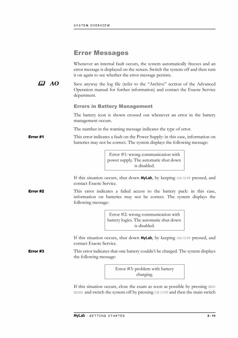
Error #1 This error indicates a fault on the Power Supply: in this case, information onbatteries may not be correct. The system displays the following message:
If this situation occurs, shut down MyLab, by keeping ON/OFF pressed, andcontact Esaote Service.
Error #2 This error indicates a failed access to the battery pack: in this case,information on batteries may not be correct. The system displays thefollowing message:
If this situation occurs, shut down MyLab, by keeping ON/OFF pressed, andcontact Esaote Service.
Error #3 This error indicates that one battery couldn’t be charged. The system displaysthe following message:
If this situation occurs, close the exam as soon as possible by pressing ENDEXAM and switch the system off by pressing ON/OFF and then the main switch
Error #1: wrong communication with power supply. The automatic shut down
is disabled.
Error #2: wrong communication with battery logics. The automatic shut down
is disabled.
Error #3: problem with battery charging.
MyLab - G E T T I N G S T A R T E D 3 - 11

S Y S T E M O V E R V I E W
GETTIN
G STA
RTED
placed on the rear panel. Switch MyLab on again and check whether themessage is still present. If the problem persists, contact Esaote personnel.
Error #4 This error indicates that at least one of the batteries has reached the maximumtemperature allowed for its working conditions. The system displays thefollowing message and shuts down automatically:
Should this situation occur, contact Esaote Service.
Power Supply Error Messages
Whenever an error in the management of the power supply occurs, thesystem displays a numbered error message: the number in the warningmessage indicates the type of error.
Error #5 This error indicates an overheating problem of the power supply. The systemdisplays the following message:
If this situation occurs, shut down the system and leave it off for a while.Verify that there is adequate ventilation to prevent the overheating of thedevice.
Should the problem persist, contact the Esaote Service department.
Error #6 This error indicates that a fan is not working. The system displays thefollowing message:
If this situation occurs, press OK and then shut down the system. Verify thatnothing is blocking the fan functioning, especially on the rear panel.
Should the problem persist, contact the Esaote Service department.
Error #4: problem with battery status. The automatic shut down will start in a
few seconds.
Error #5: overheating!Please, contact the Service department.
Error #6: problem with fan.Please, contact the Service department.
MyLab - G E T T I N G S T A R T E D 3 - 12

S Y S T E M O V E R V I E W
Error #7 This error indicates that a fault of the internal voltages occurs. The systemdisplays the following message:
If this situation occurs, press OK and then shut down the system. Contact theEsaote Service department.
Error #8 This error indicates that a fault of the impulse voltages occurs. The systemdisplays the following message:
If this situation occurs, press OK and then shut down the system. Contact theEsaote Service department.
Error #7: problem with internal voltage.Please, contact the Service department.
Error #8: wrong impulse voltage.Please, contact the Service department.
MyLab - G E T T I N G S T A R T E D 3 - 13

S Y S T E M O V E R V I E W
MyLab - G E T T I N G S T A R T E D 3 - 14
GETTIN
G STA
RTED

Chapter
4G
ETTING
STAR
TED
4. Preparing the SystemThe system will be installed by Esaote personnel. Esaote personnel will beresponsible for opening the packaging and ensuring that the system iscorrectly programmed and operational.
The information and procedure provided in this chapter will guide to preparethe system for use. Preparation includes connecting probes and externaldevices, locking articulated components for moving, and ensuring that systemoperating is met.
Acclimation TimeIf the system has been exposed to temperatures which are outside the rangegiven for its correct working (15÷35°C), it must acclimate, before beingswitched on. The following table indicates the necessary waiting times.
Table 4-1: Accl imation Time
Connecting the System to a NetworkTo use connectivity features, the system must be connected to a network.
The LAN plug is placed at the bottom of the rear side; it supports Gigabit,10Base-T, and 100Base-T Ethernet LAN. An Esaote field engineer or yournetwork administrator must configure the system for network connectivity.
1. Turn off the system power.
2. Connect one end of the provided network connection cable to the wall plug for your network.
3. Connect the other end of the cable to the network plug on the system.
4. Turn on the system.
T(C°) 60 55 50 45 40 35÷15 10 5 0 -5 -10 -15 -20
Hours 8 6 4 2 1 0 1 2 4 6 8 10 12
MyLab - G E T T I N G S T A R T E D 4 - 1

P R E P A R I N G T H E S Y S T E M
Connecting PeripheralsPeripherals, that have been ordered simultaneously with the MyLab, areusually already mounted and connected. The first mounting and connectingwill usually be performed by an Esaote technician.
NOTE Esaote suggests to contact its Service representative to install any auxiliarydevice.
Before installing the peripheral devices, make sure that the system is switchedoff and unplug the power cable from the mains outlet. Brake the wheel to fixthe system.
Powering sockets for peripheral devices are placed at the rear on the left;peripheral connections are placed at the rear, on the right. The networkconnector is placed at the rear in the bottom central position.
How to connect peripheral devices:
1. Ensure that the MyLab is switched off (complete shut down not stand-by or other conditions).
2. Connect the peripheral device to the MyLab.
3. Switch the peripheral device on, making sure that the device is not in stand-by condition.
4. Switch the MyLab on by pressing the Power ON button.
NOTE Always observe the instructions given in the manual of the peripheral/auxiliary device.
NOTE Contact Esaote personnel for recommended USB printers and for safe andproper installation.
NOTE Not all the external monitors are compatible with MyLab. Please contactyour Service representative to select an external monitor that can bemanaged by the system.
Safety Concept
MyLab is equipped with an insulation transformer to provide requiredseparation from AC mains for both the system and the auxiliary devices. Twoplugs for connecting auxiliary devices are located in the back of the systemand are accessible opening the rear door.
Additional equipment connected to MyLab must comply with respective IECor ISO standards (e.g. IEC 60950 for data processing equipment).
MyLab - G E T T I N G S T A R T E D 4 - 2

P R E P A R I N G T H E S Y S T E M
GETTIN
G STA
RTED
Furthermore, all configurations shall comply with the requirements formedical electrical systems (see IEC 60601-1-1 or clause 16 of the 3rd Editionof IEC 60601-1, respectively).
Anybody connecting additional equipment to medical electrical equipmentconfigures a medical system and is therefore responsible that the systemcomplies with the requirements for medical electrical systems. Attention isdrawn to the fact that local laws take priority over the above mentionedrequirements. If in doubt, consult your local representative or the technicalservice department.
SS The “Safety and Standards” manual provides the safety requirements andstandards to be observed for using peripherals devices with MyLab.
Medical environments
Based on IEC60601 three different conditions can be defined for patientenvironment:
Fig. 4-1: A) Patient area
Fig. 4-2: B) Medical Use Room
Intended as area B, area A excluded.
MyLab - G E T T I N G S T A R T E D 4 - 3
P R E P A R I N G T H E S Y S T E M
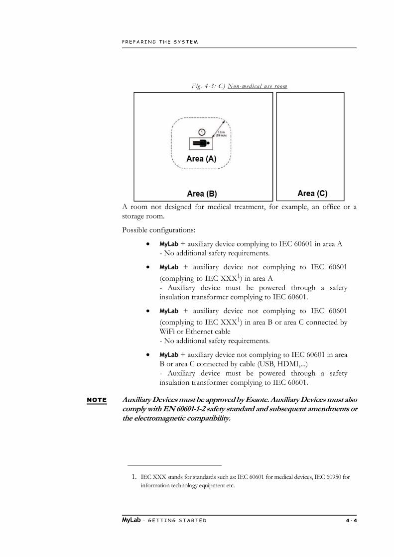
Fig. 4-3: C) Non-medical use room
A room not designed for medical treatment, for example, an office or astorage room.
Possible configurations:
MyLab + auxiliary device complying to IEC 60601 in area A- No additional safety requirements.
MyLab + auxiliary device not complying to IEC 60601
(complying to IEC XXX1) in area A- Auxiliary device must be powered through a safetyinsulation transformer complying to IEC 60601.
MyLab + auxiliary device not complying to IEC 60601
(complying to IEC XXX1) in area B or area C connected byWiFi or Ethernet cable- No additional safety requirements.
MyLab + auxiliary device not complying to IEC 60601 in areaB or area C connected by cable (USB, HDMI,...)- Auxiliary device must be powered through a safetyinsulation transformer complying to IEC 60601.
NOTE Auxiliary Devices must be approved by Esaote. Auxiliary Devices must alsocomply with EN 60601-1-2 safety standard and subsequent amendments orthe electromagnetic compatibility.
1. IEC XXX stands for standards such as: IEC 60601 for medical devices, IEC 60950 for information technology equipment etc.
MyLab - G E T T I N G S T A R T E D 4 - 4
P R E P A R I N G T H E S Y S T E M
GETTIN
G STA
RTED
Additional safety measures are:
Additional protective earth connection between the twodevices, or a safety insulation mains transformer for theauxiliary device.
Do not connect a multiple-socket outlet or extension cord toMyLab.
Avoid touching the patient and the auxiliary devicesimultaneously.
Additionally the IEC60601 requires control measurement of leakage currents.
The system integrator (any person connecting the medical device to otherdevices) is responsible that the connections are safe.
WARNING The system must be powered so to satisfy the electrical safety requirements,as specified in the “Safety and Standards” manual. Esaote recommendsrunning a current leakage (patient and environment) test when installing inorder to check whether the applicable limits of standard EN60601-1 are notbeing surpassed.
MyLab - G E T T I N G S T A R T E D 4 - 5

P R E P A R I N G T H E S Y S T E M
B/W Thermal Medical USB Printer housing
Those kinds of printers can be hosted in the lateral storage area.
Procedure 1. Connect both the power and the USB cables to the printer.
2. Insert the printer into the storage area by first introducing the cables.
3. Switch the printer on.
Auxiliary Monitor
Any auxiliary monitor connected to HDMI type port has not to be used fordiagnostic purposes.
NOTE The resolution of the auxiliary monitor cannot be lower then the maindisplay. The system automatically shuts down whenever a lower resolutionis detected.
Monitor Connection Connect the monitor cable to the connector of the rear panel.
Moving and Transporting the SystemMyLab is provided with wheels and handle to allow the user to easily move thedevice. The following precautions must be observed:
Moving the system 1. Switch the system off.
2. Engage the wheel brakes by press both pedals fully down.
3. Use the handle lever to center the control panel and move it to a comfortable height for moving.
4. Turn the mains switch off and unplug the power cord, wrapping it on the handle to ensure it.
5. Disconnect all external cables, including network and external devices.
6. Secure all cables, probes and accessories so that they do not interfere with the wheels.
7. Lock the monitor arm by rotating the lever on the monitor arm on lock position.
8. Release the wheel brakes and set the steering locks for comfortable moving.
MyLab - G E T T I N G S T A R T E D 4 - 6

P R E P A R I N G T H E S Y S T E M
GETTIN
G STA
RTED
9. Move the system using the front handle.
10. Avoid any unnecessary mechanical shock to the system while moving it.
Observe the following warnings and cautions before moving the system:
WARNING Use the handles on the keyboard only to move the system and rotate thekeyboard.
Make sure that the probes are locked and the probe cables are properlyhanged in the cable hooks while moving the system.
WARNING The handles on the keyboard cannot be used to lift the system.
To steadily lock the system, all the wheels must be locked.
Do not park the system on a slope.
Do not use the brakes to park the machine on a slope.
Avoid any unnecessary mechanical shock to the system while moving it.
Transportation When transporting the system in a vehicle, remember to:
Disconnect and remove all probes and peripheral devices.
Rotate the control panel in its closing position.
CAUTION The keyboard could be damaged during transportation in a vehicle, if it islocked.
Bring the control panel to its lowest position.
Protect the LCD screen (for example with bubble wrap) andplaced it horizontally, taking care to place something thick(such as foam or bubble wrap) between the control panel andthe LCD itself, to avoid any contact between the parts and toavoid screen swing during transportation.
MyLab - G E T T I N G S T A R T E D 4 - 7
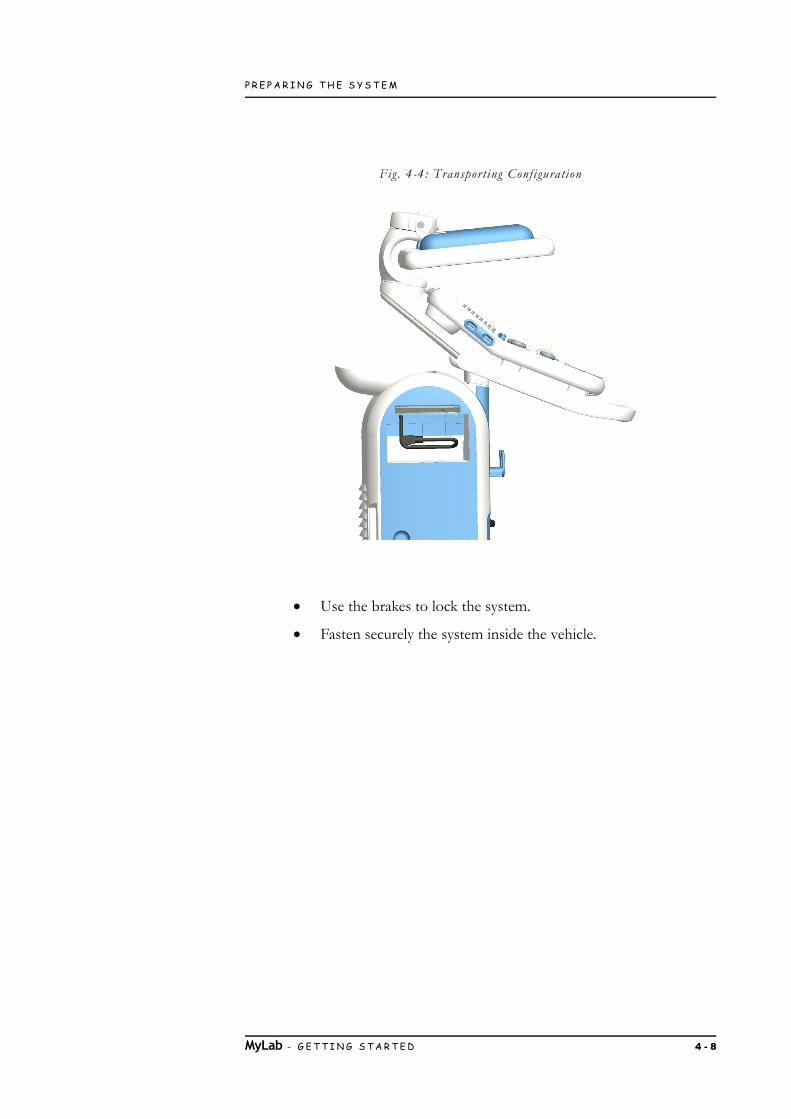
P R E P A R I N G T H E S Y S T E M
Fig. 4-4: Transport ing Configurat ion
Use the brakes to lock the system.
Fasten securely the system inside the vehicle.
MyLab - G E T T I N G S T A R T E D 4 - 8

Chapter
5G
ETTING
STAR
TED
5. Using the SystemThis chapter provides a brief description of the system controls.
AO Refer to the “Advanced Operations” Manual for further detailed information.
Connecting the system to the mainsThe power plug and the electrical main switch are located on the rear-bottomof the system. The power plug symbol is screen-printed on the consoleplastic.
Procedure 1. Plug in the power cord.
2. Connect MyLab to the power mains.
WARNING When installing MyLab, check that the power cable is not tightly bent, thatit can’t be squashed by a misplaced foot or by heavy objects.
The earth terminal can be connected to an external protective earthing systemas additional protection. This connection is not necessary in most cases andis only recommended for situations involving multiple equipment in a high-risk patient environment to provide assurance that the whole equipment is atthe same potential and operates within acceptable leakage current limits.
Turning the System On and OffAt the examination site:
1. Position the system into its final position.
2. Rotate the control panel assembly into its working position.
3. Set the control panel height into a comfortable position.
4. Engage the wheel brakes by pressing each pedal fully down.
5. Position the monitor where you want it.
MyLab - G E T T I N G S T A R T E D 5 - 1
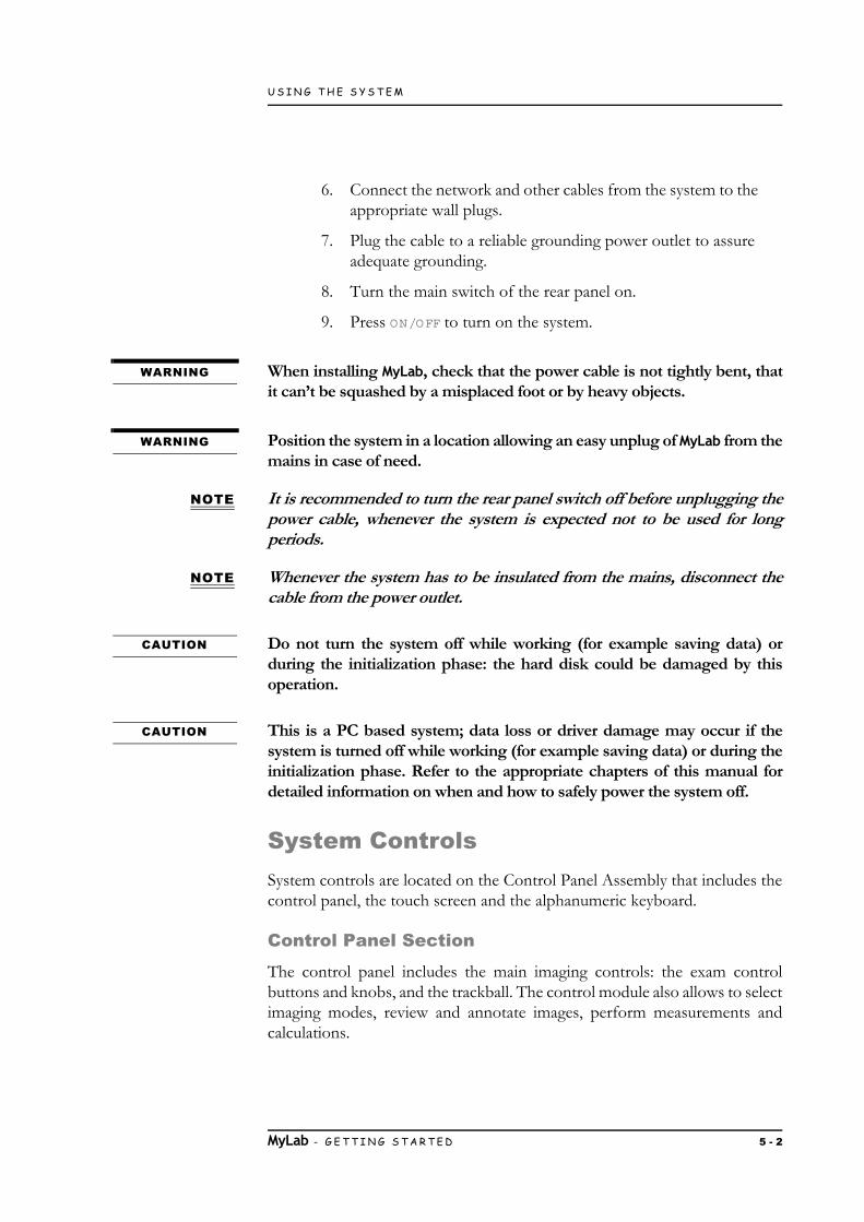
U S I N G T H E S Y S T E M
6. Connect the network and other cables from the system to the appropriate wall plugs.
7. Plug the cable to a reliable grounding power outlet to assure adequate grounding.
8. Turn the main switch of the rear panel on.
9. Press ON/OFF to turn on the system.
WARNING When installing MyLab, check that the power cable is not tightly bent, thatit can’t be squashed by a misplaced foot or by heavy objects.
WARNING Position the system in a location allowing an easy unplug of MyLab from themains in case of need.
NOTE It is recommended to turn the rear panel switch off before unplugging thepower cable, whenever the system is expected not to be used for longperiods.
NOTE Whenever the system has to be insulated from the mains, disconnect thecable from the power outlet.
CAUTION Do not turn the system off while working (for example saving data) orduring the initialization phase: the hard disk could be damaged by thisoperation.
CAUTION This is a PC based system; data loss or driver damage may occur if thesystem is turned off while working (for example saving data) or during theinitialization phase. Refer to the appropriate chapters of this manual fordetailed information on when and how to safely power the system off.
System ControlsSystem controls are located on the Control Panel Assembly that includes thecontrol panel, the touch screen and the alphanumeric keyboard.
Control Panel Section
The control panel includes the main imaging controls: the exam controlbuttons and knobs, and the trackball. The control module also allows to selectimaging modes, review and annotate images, perform measurements andcalculations.
MyLab - G E T T I N G S T A R T E D 5 - 2

U S I N G T H E S Y S T E M
GETTIN
G STA
RTED
Table 5-1: Exam Control Buttons
Button Description
ARCHIVE Gives access, at any time, to the archived data.
END EXAM Closes the current exam archiving the patient’s data and producing a report on the exam. The system clears the stored data and shows
the Exam Start menu again.
CFM Activates/deactivates Color Doppler (CFM). The knob around this button amplifies both CFM and Power Color gains. To increase
gain, turn the knob clockwise, to reduce it, turn the knob counter-clockwise. In B-Mode, a cursor delimits the Region of Interest
(ROI) where color analysis is performed and displayed.
PW Activates the Pulsed Wave Doppler (PW). At its pressure the positioning cursor is activated as well. The knob around this button amplifies both CW and PW gains. To increase gain, turn the knob
clockwise, to reduce it, turn the knob counter-clockwise.
PW R D Activates the Power Color Doppler or Tissue Velocity Mapping.
CW Activates the Continuous Wave Doppler (CW). At its pressure the positioning cursor is activated as well.
M EASURE Activates Advanced Measurements showing the list of available measurements on the right of the image.
+...+ Activates Generic Measurements showing the list of available measurements on the right of the image.
POINTER Toggles the trackball operation from standard to mouse mode. Refer to the “Trackball” paragraph further in this chapter.
ACTION Changes the function linked to the trackball. Refer to the “Trackball” paragraph further in this chapter.
AUTOADJUST The AUTOADJUST key, available both in B-Mode and Doppler, automatically adjusts some controls of the active mode to make the
echo acquisition easier.
M Activates the M-Mode and, if necessary, its selection cursor (B-Line)
B/M This button re-activates a B-Mode image in real time when any other mode is active. If pressed in M-Mode, Doppler or Freeze, it restores a full screen bi-dimensional image. The knob around this button amplifies both B-Mode add M-Mode gains over the entire depth of the image. To increase gain, turn the knob clockwise, to
reduce it, turn the knob counter-clockwise.
MyLab - G E T T I N G S T A R T E D 5 - 3

U S I N G T H E S Y S T E M
Trackball
The trackball operates in two different modes.
Standard Mode In its standard mode, the trackball makes it possible to quickly position thecursors on the screen.
Each mode automatically activates the trackball on its cursor.
Table 5-2: Trackball cursors
3D/4D Activates three dimension features; further details on how to use them are described in the “Advanced Operations” manual
LINE UPDATE In B-Mode or CFM, this button allows to interactively activate the cursor or disable it to select the M-Mode or Doppler line.
During the exam, when a trace is active, the same button freezes the trace acquisition and temporarily reactivates the reference B-Mode
image.
ACQUIRE Activates advanced features; further details on how to use them are described in the “Advanced Operations” manual.
IM AGE During the exam it saves single images. The stored images are displayed as thumbnails on the right of the screen.
CLIP During the exam it saves a sequence of images. The stored clips are displayed as thumbnails on the right of the screen.
FREEZE Stops the current analysis or scan and puts the system in Freeze mode. To re-activate real time, press it again or directly press the
button of the required mode.
DUAL Activates dual and quad view both in real time and freeze.Press LEFT or RIGHT to activate dual presentations: the active image
is displayed on the left/right. Press CENTER to restore a single format.
Press CENTER to activate quad presentations: the active image is displayed on the top-left. Press LEFT or RIGHT to add other images.
Press CENTER to restore a single format.
1, 2 These buttons can be customized to print images. Refer to chapter 6 “Customizing the system” for further information.
Button Description
Mode Trackball
M-Mode, Doppler LINE cursor
Color Flow Mapping (CFM) CFM ROI cursor
MyLab - G E T T I N G S T A R T E D 5 - 4

U S I N G T H E S Y S T E M
GETTIN
G STA
RTED
The cursor function is indicated below the image. When several cursors arepresent on the screen, ACTION switches between the active cursors. Yellowindicates active cursor function while white next cursor function.
Mouse Mode In its mouse mode, the trackball can be used to move a pointer on the screen,to access to the thumbnails of the images, displayed on the right side of thescreen or to access to the archiving media and peripheral menus. The buttonsplaced on the left and right side of the trackball can be set as mouse keys (asconfirmation and context menu buttons).
Regardless of the trackball configuration, the confirmation and context menubuttons are respectively indicated as ENTER and UNDO in this manual.
Press POINTER to change the trackball operation from standard to mousemode.
Touchscreen Section
This section includes the ON/OFF, the M ENU and ETOUCH buttons, atouchscreen and the TCG Sliders.
On/Off Button
The ON/OFF button is located beside the touchscreen, on the left side of thecontrol panel assembly, while the Main Switch is located on the rear-bottomof the system.
Beside the Main Switch is also located an earth terminal to be connected toan external protective earthing system as additional protection.
When MyLab is connected to the mains and the Main Switch is on, the lightingof the ON/OFF button changes to indicate its status. The different indicatorsare described in the table below.
Table 5-3: On/Off button l ight
Pressing the ON/OFF button turns the system on or off, activating or closingthe examination session.
Led Colour Meaning
GREEN MyLab is on
AMBER MyLab can be turned on
OFF MyLab can not be turned on. In this case check both the rear main switch and the mains connection.
MyLab - G E T T I N G S T A R T E D 5 - 5

U S I N G T H E S Y S T E M
Optional Batteries When MyLab is equipped with optional batteries, the same button places thesystem in stand-by, partially shutting it down: in this case the initializationphase at start up is significantly reduced.
NOTE A complete shut down procedure is periodically and automatically run toprevent misfunctioning: when this occurs, MyLab displays an informationmessage. The following start up will require running the wholeinitialization phase.
Menu Button
M ENU displays the system menu for all configurations/settings (both clinicaland system settings).
ETOUCH Button
Touchscreen
The touchscreen displays controls used to select probes, enter patient data,select applications and change setups; it also displays exam controls related tothe active modality.
Touchscreen controls are indicated in the operator manuals by BOLD BLUECAPITAL LETTERS for keys that can be taped while by NORMAL BLUE CAPITAL
LETTERS for software text strings.
Tap the displayed key to activate/deactivate the corresponding control.
Many modes provide two pages of controls: tap ADV>>/BASIC<< to switchfrom the first page to the second page.
The touchscreen layout changes depending on the different workingmodality:
as exam panel, providing control keys to perform the exam,
as multipurpose panel, providing keys for advancedfunctions,
as alphanumeric keyboard to enter data.
ETOUCH Toggles between factory and customized touchscreen that can becreated by the user. Refer to the chapter “Customizing the system”further in this manual.
MyLab - G E T T I N G S T A R T E D 5 - 6
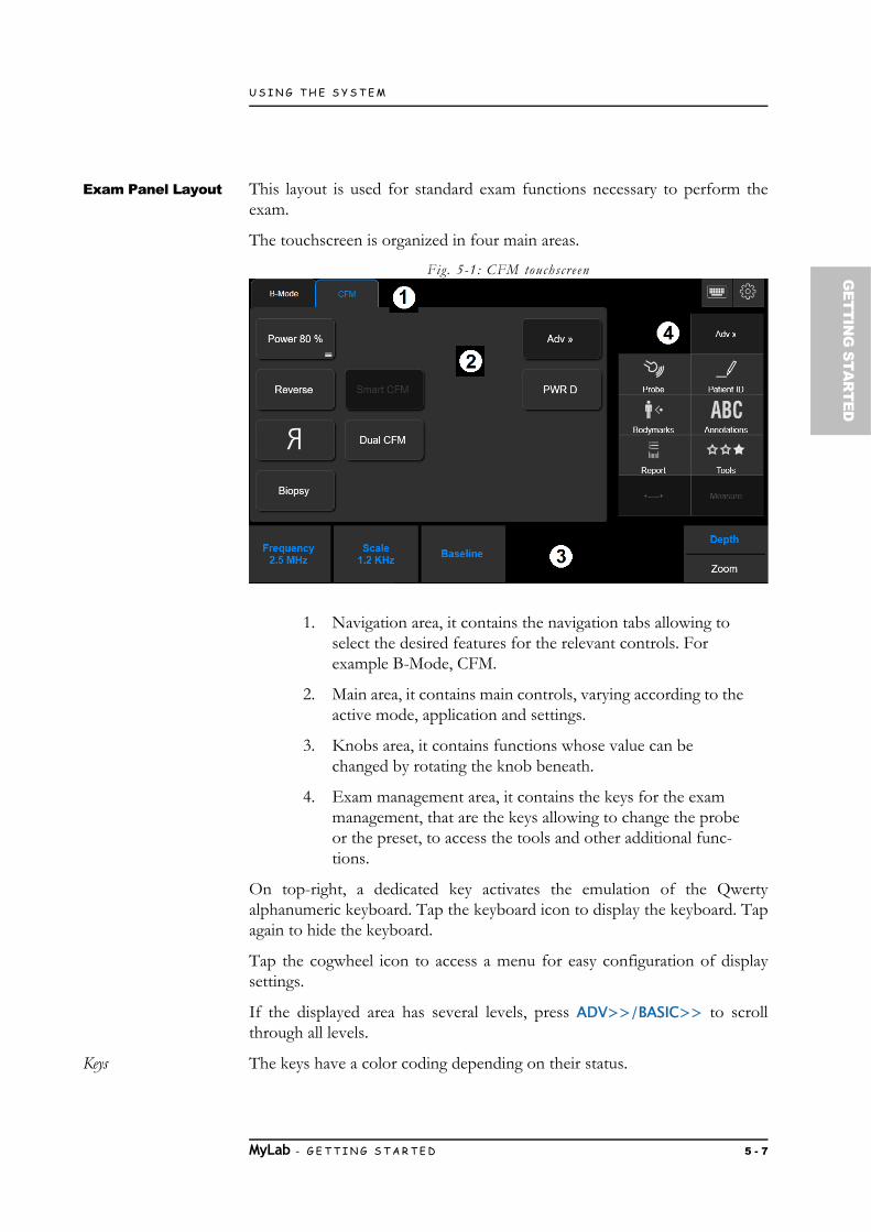
U S I N G T H E S Y S T E M
GETTIN
G STA
RTED
Exam Panel Layout This layout is used for standard exam functions necessary to perform theexam.
The touchscreen is organized in four main areas.
Fig. 5-1: CFM touchscreen
1. Navigation area, it contains the navigation tabs allowing to select the desired features for the relevant controls. For example B-Mode, CFM.
2. Main area, it contains main controls, varying according to the active mode, application and settings.
3. Knobs area, it contains functions whose value can be changed by rotating the knob beneath.
4. Exam management area, it contains the keys for the exam management, that are the keys allowing to change the probe or the preset, to access the tools and other additional func-tions.
On top-right, a dedicated key activates the emulation of the Qwertyalphanumeric keyboard. Tap the keyboard icon to display the keyboard. Tapagain to hide the keyboard.
Tap the cogwheel icon to access a menu for easy configuration of displaysettings.
If the displayed area has several levels, press ADV>>/BASIC>> to scrollthrough all levels.
Keys The keys have a color coding depending on their status.
MyLab - G E T T I N G S T A R T E D 5 - 7

U S I N G T H E S Y S T E M
Table 5-4: Touchscreen key s tatus
If the key is active, the displayed function will be enabled when tapping thecorresponding key on the touchscreen.
Knobs Six rotating knobs are located along the bottom side of the touchscreen.
Each knob acts on the control key just above it. Rotate the knob to changethe control value.
Sometimes, two controls are available for a knob. Only one of the controlscan be active at a time. Pressing the corresponding knob or tapping the labeltoggles the active control.
Multipurpose Panel Layout
This layout is used for advanced exam functions, for example body marks orannotations.
Fig. 5-2: Annotat ions touchscreen
AO Refer to the “Advanced Operations” manual for further details.
Disabled Key Active KeyActive Key with
SubmenuSelected Key
Gray text on dark gray background
White text on light gray background
As Active Key with three lines at bottom right
Blue text on dark gray background
MyLab - G E T T I N G S T A R T E D 5 - 8

U S I N G T H E S Y S T E M
GETTIN
G STA
RTED
Alphanumeric Keyboard Layout
The alphanumeric keyboard is based on the QWERTY standard. Thealphanumeric keys are used to enter text data in the enabled windows. TheCaps Lock key sets the keyboard to upper case characters.
The Shift key is used to type in lower case or upper case characters(according to how the keyboard is set); the Fn key is used to type numericfunctions (for example +, *).
AO Refer to the “Advanced Operations” manual for the use of the keyboard inannotation modality.
TGC Sliding
The TGC sliding control signal amplification in individual areas of the image.Potentiometers are used to adjust the signal zone by zone.
Information about the Screen LayoutThe screen is split into four main areas.
Fig. 5-3: Screen Layout
1. Heading Area
2. Footer Area
3. Image Area
4. Thumbnails Area
MyLab - G E T T I N G S T A R T E D 5 - 9

U S I N G T H E S Y S T E M
Controls on the Screen Layout are indicated in the operator manuals withBOLD BLACK CAPITAL LETTERS , while strings and fields are indicatedwith NORMAL BLACK CAPITAL LETTERS.
Symbol on Screen When this symbol is displayed on the screen, it indicates to carefully read themanual. Refer to the appropriate section of the manual for a detailedexplanation.
Heading Area
This area is used to display the following information: center and patient data,accession number and date.
Patient data are displayed only if entered at the beginning of the exam.
Data can be entered or modified at any time during the exam by pressingPATIENT ID.
Footer Area
This area is used to display the following information:
trackball functionality,
Wi-Fi icon (when enabled),
archival media icons,
advanced features icons,
battery icons,
peripherals icons.
Trackball
The trackball function is indicated below the image as text.
When there are several cursors on the screen, two functions are displayedsimultaneously. The function shown in yellow on the upper line indicates theactive cursor; the one in white on the lower line indicates the next cursor thatcan be activated. ACTION switches among cursors.
Wi-Fi
When Wi-Fi is enabled, its icon is shown beside the archival media icons. Theicon is shown crossed out whenever Wi-Fi is not connected.
AO For more details on Wi-Fi connectivity, consult the relevant section on the“Advanced Operations” manual.
MyLab - G E T T I N G S T A R T E D 5 - 10

U S I N G T H E S Y S T E M
GETTIN
G STA
RTED
Archival Media
Archival media are shown on the left. The icon is shown crossed outwhenever there are management problems involving the specific archivalsystem.
AO For more details on data archival, consult the relevant section on the“Advanced Operations” manual.
Advanced Features
When advanced features such as XView or MView are activated, thecorresponding icons are displayed on the center of the footer area.
Battery
When the battery pack is installed, battery status icons are displayed.
Peripheral Devices
The system is able to simultaneously manage two peripheral devices (b/w orRGB printers). The icons of the peripheral devices are shown at right of thefooter area. The icon is shown crossed out whenever there are managementproblems involving the specific peripheral device.
MyLab - G E T T I N G S T A R T E D 5 - 11

U S I N G T H E S Y S T E M
Image Area
The visualization of the image depends on various factors such as the activemode, the selected application and the probe. The following figure shows theelements in the image area that are independent of these factors.
Fig. 5-4: Image Area
Table 5-5: Image Area descr ipt ion
Freeze Status Whenever an image is frozen, a memory bar is displayed (at bottom right)concerning the scrolling memories. The images acquired immediately beforeare frozen and archived in these memories. The trackball can be used toexamine the B-Mode, M-Mode, Doppler and color information image byimage.
Number Description
1 Frequency Bar, active application, probe and preset
2 System Parameter
3 Sector orientation
4 Acoustic output data
5 Focal Zone(s)
6 Image and color scales
7 Memory bar
MyLab - G E T T I N G S T A R T E D 5 - 12

U S I N G T H E S Y S T E M
GETTIN
G STA
RTED
Machine Parameters
Table 5-6: Imaging Parameters
SV and are displayed only if the relevant cursor is active.
Table 5-7: Color Flow Mapping (CFM) Parameters
ParameterDisplayed
formatDescription
F l Imaging or TEI (Tissue Enhancement Imaging) mode: General, Resolution or
Penetration (L: Low, H: High)
G nn% Imaging gain (Min,%, Max)
AG nn% Auto Adjust
D nn mm Depth
X/M C or +n/n XView Algorithm or CrystaLine Imaging /MView algorithm
PRC n/n/n/n Dynamic range / Dynamic compression /Density / Gray map
PRS n Persistence
SV nn/nnn mm Sample volume size and depth
nn° Doppler angle correction
ParameterDisplayed
formatDescription
F nnn MHz Color frequency or TVM (Tissue Velocity Mapping) frequency when enabled
G nn% Color gain (Min,%, Max)
PRF nnn kHz Pulse Repetition Frequency
WF n Wall filter
PRC l/n Smooth (L: Low, M: Medium, H: High) / Density
PRS n Persistence
MyLab - G E T T I N G S T A R T E D 5 - 13
U S I N G T H E S Y S T E M
Table 5-8: Doppler Parameters
Thumbnails Area
Clips and images both saved during the exam and previously archived aredisplayed on the right side of the screen as thumbnails. The thumbnails aredisplayed in chronological order, from left to right.
The tabs displayed at the top of the thumbnails columns allow to scrollamong the images saved during current exam and images retrieved from otherexams.
ParameterDisplayed
formatDescription
F nnn MHz Doppler frequency or TV (Tissue Velocity) frequency when enabled
G nn% Doppler gain (Min,%, Max)
PRF nnn kHz Pulse Repetition Frequency
PRC n/n Dynamic range / Rejection
WF nnn Hz Wall filter
PRC n/n Dynamic range / Gray map
MyLab - G E T T I N G S T A R T E D 5 - 14

Chapter
6G
ETTING
STAR
TED
6. Customizing the SystemMyLab can be customized to increase efficiency and streamline your work-flow. You can do the following:
Create preset designed specifically for the exams youperform.
Change system settings to reflect your needs.
Add options to enhance your imaging abilities.
Create custom procedures for specific patients, transducers,and presets.
The M ENU button is used to access the system menu. The system displays allthe available options.
Fig. 6-1: System Menu
MyLab - G E T T I N G S T A R T E D 6 - 1

C U S T O M I Z I N G T H E S Y S T E M
The menu is organized in three areas:
Clinical Configuration, the upper area shows all optionsrelating to Clinical Settings or Presets,
System Settings, the central area shows all options relating toSystem Settings,
General Settings, the lower area shows all options relating toGeneral Settings.
Clinical Configuration
A clinical setting is a group of configurations optimizing MyLab for a specifictype of exam (for example for a cardiac exam or an obstetrical exam). Thisclinical setting is associated to the specific probe in the selected application.
You can save several clinical settings for each probe in each application. Thismeans that the preset, selected at the beginning of the exam or during theexam pressing PROBE, establishes the initial settings of the exam controls (likegray map, depth...) together with the initial available measures (measurementconfiguration), the initial available library both for annotations and forbodymarks (Annotation and Bodymark configurations) and the customizedtouchscreen.
Clinical Configuration allows to set different parameters listed below:
Real Time Preset for Presets configuration,
Measure for measurement configuration,
Annotations for annotation configuration,
Bodymarks for bodymark configuration,
eTouch for eTouch configuration,
When licensed, advanced tool configurations (such as 3D/4D, Stress Echo) are part of the clinical settings.
NOTE Refer to the dedicated sections of this manual for further information on theabove Clinical Configurations.
MyLab - G E T T I N G S T A R T E D 6 - 2

C U S T O M I Z I N G T H E S Y S T E M
GETTIN
G STA
RTED
System Settings System Settings define the MyLab’s parameters related to a specific systemprofile:
Profile Manager,
DICOM configuration,
Saving Options for end exam saving configuration,
Center ID for hospital configuration to set the name of thehospital,
Multimedia,
Network for network configuration,
Observations for observation configuration,
Printers for printer configuration,
Report for report style configuration,
XStrain2D,
Acquisition Protocols.
You can save several system profiles. If, for example, MyLab is used in twostructures differing in Network and DICOM connectivity, two specificSystem Configuration profiles can be created: each time the user will load theconfiguration required by the structure.
MyLab allows the user to save several system configurations. If, for example,MyLab is used in two structures differing in Network and DICOMconnectivity, two specific System Configuration profiles can be created: eachtime the user will load the configuration required by the structure.
General Settings General Settings define the MyLab’s general parameters:
General Setup for general configuration, like measure units,control panel setting,
Security for general configuration,
Licenses for license settings,
Import/Export for exam export configuration,
System Info,
Remote Service,
ePortal.
MyLab - G E T T I N G S T A R T E D 6 - 3

C U S T O M I Z I N G T H E S Y S T E M
Generic Configuration ProcedureOnce accessed the configuration screen for the parameter you want to set, acommon set of commands is available and a common setting procedure canbe used.
In a few limited cases the procedure may differ to the one described below,in these cases it will be described in the specific paragraph.
Procedure Press M ENU, and select the parameter you want configure.The configuration screen for the selected parameter isdisplayed.
On the left of the screen is displayed the list of possibleitems.
Select the desired item, then choose one of the followingoptions.
Table 6-1: Configurat ion Menu Options
Once in editing mode you can change the name of theselected item (NAME field), enter a description (NOTES field),confirm and save the settings (SAVE ), or exit the menuwithout saving the settings (CANCEL ).
At any time you can go back to the main menu (BACK TO MENU ) or exitfrom the menu and go back to Real Time (CLOSE ).
Option Description
EDIT To modify the settings of the item selectedon the top-left list.Alternatively double click on the item youwant to modify
CLONE To create a new customized item startingfrom a copy of the existing selected one.
NEW It replaces CLONE when no customizeditems are present.
REMOVE To delete the selected customized item. Aconfirmation dialog will be displayed. Onlycustomized items can be deleted.
FACTORY To retrieve all factory values and to deleteall customized items.
MyLab - G E T T I N G S T A R T E D 6 - 4

C U S T O M I Z I N G T H E S Y S T E M
GETTIN
G STA
RTED
Clinical Configurations AO This chapter explains how to set many MyLab options. For configurations not
described here refer to relevant chapters in the “Advanced Operations” manual.
Real Time Preset
A Preset is a group of settings that optimizes the system for a specific type ofexam. Presets establish many initial settings, such as gain value, color map,filter and items on the touchscreen.
You can choose from several default presets, modify them and create manyothers. Default presets can not be deleted, however, they provide a startingpoint from which you can create your own presets.
The available presets are determined by the selected transducer.
The creation/modification of a preset is achievable in two steps:
from M ENU, where you can add the desired measurementconfiguration, annotation and bodymark libraries,
from Real Time, where you can set the parameters thatoptimize the real time image in all modes and create thecustomized preset.
Creating a new preset from MENU
To create a new preset or modify an existing one press M ENU, then selectREAL TIME PRESET and then follow the generic configuration procedure,taking in account that on the left of the screen is displayed the list of all clinicalsettings, grouped by probes. Within each probe clinical settings are groupedby applications.
During editing you can select from the curtain menu each parameter(Measure, Annotation, Body Marks...) to be associated of the preset in thedesired configuration.
Here you can also assign the default application for each probeindependently. Each time the probe is selected its default application isselected as well.
When selecting each probe you can also establish which application to showon the touchscreen. Uncheck the application in order not to show it. Theoption ALL PROBES allows to select/unselect the application for all probes.
The configured preset is associated to the active probe and application: thispreset will be available each time the same probe and application are selectedeither from the Start Exam page or by tapping PROBE.
MyLab - G E T T I N G S T A R T E D 6 - 5

C U S T O M I Z I N G T H E S Y S T E M
Creating a new preset from Real-Time
Procedure To create a new preset or modify an existing one:
Adjust the real time image as desired in all modes (2D, CFMand Doppler).
Tap PROBE and then PRESET MANAGER.
Press OVERWRITE to overwrite the current preset (alsofactory presets can be overwritten) or using the alphanumerickeyboard type a new preset NAME and NOTE and press NEWto confirm.
OVERWRITE saves all settings done in real time in the active preset.
NEW creates a new preset whose configuration is the one defined in everymodality in real time.
CLOSE exits without saving any modification.
eTouch Button
MyLab allows the user to record sequences of keys both of the touchscreenand of the control panel. Each recorded sequence (Macro) can be named andsaved to be available as customized button in customized touchscreens.
ETOUCH switches between factory and customized touchscreen. Whenever thecustomized button is pressed, MyLab will automatically launch the keyssequence.
Each system configuration is linked only to one customized touchscreen.
NOTE Keys sequences that require interaction with the user (like measurementsor pointer positioning) can not be recorded as macro.
Configuring eTouch button
To access to the ETOUCH configuration menu:
Press M ENU. The configuration menu is organized in twomain areas: the list of all saved customized touchscreens onthe left side and the eTouch configuration menu on the rightside.
Select one of the saved customized touchscreens, then followthe generic configuration procedure.
During editing the screen displays:
in the center the touchscreen layout,
MyLab - G E T T I N G S T A R T E D 6 - 6
C U S T O M I Z I N G T H E S Y S T E M
GETTIN
G STA
RTED
on the right the menu to record the macro and to edit thecustomized buttons,
on the bottom the fields where customized touchscreens arenamed and described.
From here you can:
Record the Macro sequence,
Customize the touchscreen,
Create additional tabs on the touchscreen.
To create a customized touchscreen, follow one of the following procedures.
NOTE Wait for any background operations to be finished before starting theprocedure.
Recording Procedure
Place the cursor on the RECORDING field and press STARTto begin the recording: MyLab switches to the frozen status.
The system displays on the upper left side of the screen thefollowing flashing message:
Prepare MyLab to be ready for the recording so that only the keysto be used can be pressed and then press ETOUCH to start.
Press the desired keys in sequence and press again ETOUCH toend the recording. During the sequence recording, themessage turns color.
The eTouch configuration menu displays the customized button. Place thecursor on the button and press ENTER to change its name, using thealphanumeric keyboard to edit it.
Repeat the procedure to add other customized buttons.
Customized Button Organizations
The customized button can be freely positioned within the touchscreen.
MOVE BUTTON changes the button position: select the button with thetrackball, place the cursor on the desired position and click ENTER to confirm.
DELETE BUTTON cancels the button selected with the trackball.
Tab Organization Customized touchscreen can be organized in more tabs. Each tab has onelevel of buttons.
Press eTouch to start recording.
MyLab - G E T T I N G S T A R T E D 6 - 7

C U S T O M I Z I N G T H E S Y S T E M
NEW TAB button adds a new tab that will be automatically displayed. Placethe cursor on the tab and press ENTER to change its name, using thealphanumeric keyboard to edit it.
MOVE LEFT and MOVE RIGHT buttons respectively shift to left or to rightthe selected tab: select the tab with the trackball and press the desired button.
DELETE SELECTED TAB button cancels the tab selected with the trackball.
NOTE Empty tabs (that is tab not containing customized button) are notdisplayed in the customized touchscreen.
System Settings AO This chapter explains how to set many MyLab options. For configurations not
described here refer to relevant chapters in the “Advanced Operations” manual.
Profile Manager
Profile Manager allows to create a system profile for each user with a personalizedsystem configuration.
To configure the Profile press M ENU, then select PROFILE MANAGER andthen follow the generic configuration procedure.
During editing you can configure each displayed component selecting thedesired option among the ones available in the relevant SETTINGS combo.
Fig. 6-2: Profile Manager Menu
MyLab - G E T T I N G S T A R T E D 6 - 8

C U S T O M I Z I N G T H E S Y S T E M
GETTIN
G STA
RTED
Corrupted System Profile
Whenever a profile is corrupted, a red exclamation mark is displayed on the ProfileManager option. In this case, enter the profile manager menu and, for each systemprofile, check that every component has a specific setting (no component has tobe without any setting).
Should this not solve the problem, contact Esaote personnel.
Center ID
Center ID allows to set the center name displayed in the Heading Area of thescreen and the center information shown in the report.
To configure the Center ID press M ENU, then select CENTER ID and thenfollow the generic configuration procedure.
During editing you can configure many fields described below.
Center ID Field
The name entered in this field will be displayed in the heading area of the screen.
Report Information Field
This option allows to add to the report header the following information:
the hospital name;
the department name;
the contact details;
two fields for other additional information;
the hospital logo.
DICOM Field
This option allows to enter the station name used in DICOM.
General Settings AO This chapter explains how to set many MyLab options. For configurations not
described here refer to relevant chapters in the “Advanced Operations” manual.
NOTE Some settings described below may be unavailable on your product’sconfiguration.
MyLab - G E T T I N G S T A R T E D 6 - 9

C U S T O M I Z I N G T H E S Y S T E M
General Setup
The menu is organized in internal folders, selectable using the tabs displayed on thetop of the menu.
Fig. 6-3: General Conf iguration Menu
SAVE saves the settings, which will be activated as soon as they are saved.
CANCEL exits the menu without saving the new settings.
FACTORY retrieves all factory values and deletes all customized items.
DATE/TIME Folder
This option is used to set date and time, displayed on the screen.
Set Date Using the trackball scroll the month and select the day on the calendar.
Date Format Various formats can be set: the available options are listed in the following table.
Table 6-2: Date Formats
Format Displayed date
DD/MM/YYYY 01/04/2011
DD/MMM/YYYY 01/Apr/2011
MM/DD/YYYY 04/01/2011
MMM/DD/YYYY Apr/01/2011
MyLab - G E T T I N G S T A R T E D 6 - 10

C U S T O M I Z I N G T H E S Y S T E M
GETTIN
G STA
RTED
Set Time Using the keyboard set the time.
Time Format The time format is available on a 24 or 12 hour basis. In the 12 hour option, thetime is shown as AM and PM.
MEASURE UNITS Folder
This option is used to set the desired units for height and weight. You can choosebetween cm/kg and ft/lb.
The Celsius or Fahrenheit scale can be selected for probes equipped withtemperature sensor.
BIOPSY Folder
This option is used to set the type of needle guide line to be superimposed on theimage during biopsy procedures. For further information about biopsy and needleguides, refer to the related chapter in the Advanced Features section of theAdvanced Operations manual.
MyLab - G E T T I N G S T A R T E D 6 - 11

C U S T O M I Z I N G T H E S Y S T E M
CONTROL PANEL Folder
The table below lists and explains the available fields and the correspondingactions.
Table 6-3: Control Panel Folder
Fields Action
TRACKBALL SPEED Sets the speed of the trackball.
TRACKBALL ACCELERATION
When checked, it adjusts cursor pointer acceleration in order to react exactly on how quickly you move
your trackball.
LEFT CLICK Sets the action of the left key of the trackball.The left key can be set as confirming key (ENTER)
or as context menu key (UNDO )
CHARACTER SET Sets the characters used for all the system information (for example screen information,
touchscreen button).
SHUTDOWN TYPE Sets the preferred shutdown type.
SCREEN RESOLUTION Sets the screen resolution when secondary monitor is connected.
AVAILABLE QWERTIES Sets which alphanumeric keyboards are available in the touchscreen and which is the default one.
When more alphanumeric keyboards have been set, the touchscreen displays an alphanumeric keyboard
with dedicated tabs allowing to select the desired keyboard.
BEEP VOLUME Sets the volume of the beep.
FOCUS CONTROLLED BY TRACKBALL
Sets the default action of the trackball when starting the exam.
ETOUCH BUTTON When Acquisition Protocol is licensed, the eTouch button can be configured to work with protocols.
DEPTH INCREASE Allows to set the depth changing the value clockwise/counterclockwise.
AUTOMATIC START EXAM
When checked, it allows a direct access to B-Mode after booting without passing through Patient ID.
MyLab - G E T T I N G S T A R T E D 6 - 12
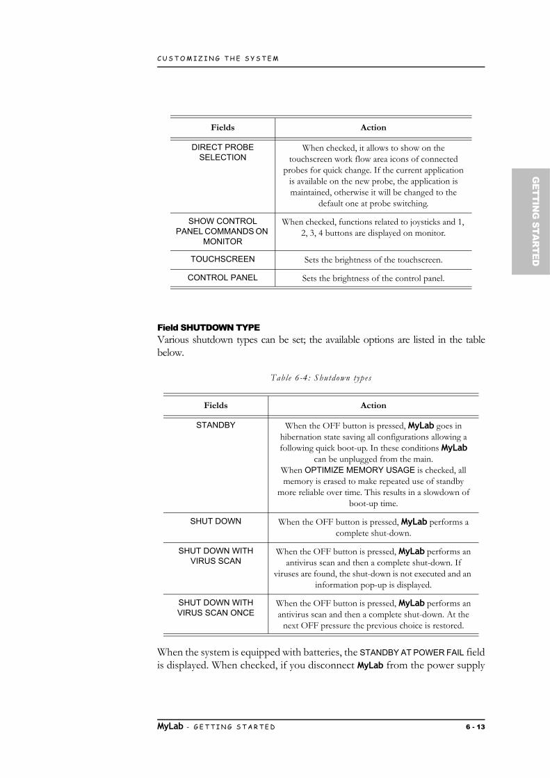
C U S T O M I Z I N G T H E S Y S T E M
GETTIN
G STA
RTED
Field SHUTDOWN TYPEVarious shutdown types can be set; the available options are listed in the tablebelow.
Table 6-4: Shutdown types
When the system is equipped with batteries, the STANDBY AT POWER FAIL fieldis displayed. When checked, if you disconnect MyLab from the power supply
DIRECT PROBE SELECTION
When checked, it allows to show on the touchscreen work flow area icons of connected
probes for quick change. If the current application is available on the new probe, the application is maintained, otherwise it will be changed to the
default one at probe switching.
SHOW CONTROL PANEL COMMANDS ON
MONITOR
When checked, functions related to joysticks and 1, 2, 3, 4 buttons are displayed on monitor.
TOUCHSCREEN Sets the brightness of the touchscreen.
CONTROL PANEL Sets the brightness of the control panel.
Fields Action
STANDBY When the OFF button is pressed, MyLab goes in hibernation state saving all configurations allowing a following quick boot-up. In these conditions MyLab
can be unplugged from the main.When OPTIMIZE MEMORY USAGE is checked, all memory is erased to make repeated use of standby
more reliable over time. This results in a slowdown of boot-up time.
SHUT DOWN When the OFF button is pressed, MyLab performs a complete shut-down.
SHUT DOWN WITH VIRUS SCAN
When the OFF button is pressed, MyLab performs an antivirus scan and then a complete shut-down. If
viruses are found, the shut-down is not executed and an information pop-up is displayed.
SHUT DOWN WITH VIRUS SCAN ONCE
When the OFF button is pressed, MyLab performs an antivirus scan and then a complete shut-down. At the
next OFF pressure the previous choice is restored.
Fields Action
MyLab - G E T T I N G S T A R T E D 6 - 13

C U S T O M I Z I N G T H E S Y S T E M
without pressing the OFF key, MyLab enters autonomously in hibernationmode by saving all the configurations that allow a subsequent rapid restart.
NOTE Esaote does not install a real-time antivirus program, because it could affectthe regular operations of MyLab.
The antivirus scan could take a long time. Before starting the scan, aconfirmation is requested.
If a virus is found, it is advisable to switch off the MyLab, disconnect it fromthe data network and call the Esaote service, which will check for thepresence of a virus and restore the system.
Field AVAILABLE QWERTIESWhen more alphanumeric keyboards have been set, the touchscreen displays analphanumeric keyboard with dedicated tabs allowing to select the desiredkeyboard.
Fig. 6-4: Qwerty keyboard
CINE MODE Folder
When set, the AUTOMATIC PLAY and TRACE AUTOMATIC PLAY optionsrespectively allow to review the stored images and the trace in cine mode whenFREEZE is pressed.
APPLICATION PRESET Folder
This option is used to set specific features for each application.
The menu is organized in two areas: the left side shows the list of the availableapplications, the right side the list of the features.
Select the application and then check the boxes of the desired features.
The table below lists and explains the available fields and the correspondingactions.
MyLab - G E T T I N G S T A R T E D 6 - 14

C U S T O M I Z I N G T H E S Y S T E M
GETTIN
G STA
RTED
Table 6-5: Applicat ion Preset Folder
WARNING The displayed Sweep Velocity is correct as long as you do not use asecondary monitor and/or an incorrectly calibrated monitor.
Fields Action
ABSOLUTE ANGLE The angle correction factor of linear probes can be correlated either to the line cursor or to the line
perpendicular to the transducer surface (absolute angle).In the first case the angle correction is kept constant when the line is moved; in the latter case an angle correction is
calculated whenever the line is moved.
SHOW SWEEP VELOCITY
When checked, this option allows to display the Sweep Velocity (cm/s) below the PW/CW/M scroll area.
SAMPLE VOLUME SWIVELING STEERING
When checked, the Doppler line can be oriented by using the center of the sample gate as rotation axis.
SHOW ZOOM REFERENCE WINDOW
When checked, the zoom navigation window is displayed on the screen just as the zoom has been activated.
USE REFERENCE BOX ON DUAL COLOR
DOPPLER
When checked, in dual visualization, the ROI box is overlaid to the B-Mode image as a reference.
IMAGE SIZE Sets the default dimension for reference image in split format for the selected application.
ACTION ON FREEZE Sets the action after FREEZE pressure.
AUTO BUTTON SETUP Sets the action after AUTO pressure: AUTOADJUST (to automatically adjust the B-Mode image), ECFM (to
automatically optimize CFM image) or BOTH of them.
EASYTRACE ENABLED When checked, this option allows to enable easyTrace.
IMAGE AUTOFITTING When checked, for linear probes and superficial depths, it adapts the size to the width of the screen.
ENABLE SMARTOUCH When checked, it enables the smarTouch for the selected application.
INVERT CFM SCALE WITH STEERING
When checked, this option allows to automatically invert the Doppler scale when inverting the steering with reference
to the vertical line.
USE REFERENCE BOX ON DUAL ELAXTO
When checked, in dual visualization, the ROI box is overlaid to the B-Mode image as a reference.
MyLab - G E T T I N G S T A R T E D 6 - 15
C U S T O M I Z I N G T H E S Y S T E M
FOOTSWITCH Folder
This option is used to set which function is associated to each pedal (left, middleand right) of the footswitch.
Select from the curtain menu the function then press SAVE .
PROBE BUTTONS Folder
This option is used to set which function is associated to each probe button.
Select from the curtain menu the function then press SAVE .
RAW DATA Folder
When the associated license is enabled and the option selected, data are saved inraw format for Post Processing elaboration.
Refer to the “Archive” section of this manual for further information on thisfeature.
KEYBOARD BUTTONS Folder
This option is used to set which function is associated to ACQUIRE button and toeach of the four configurable buttons (1, 2, 3, and 4).
From the curtain menu select the function you desire then press SAVE .
NOTE When the buttons 1, 2, 3, 4 are associated to save image or save clip, theywill be named further in this manual as IM AGE or CLIP respectively.
Security
For further information about security options provided by MyLab, refer to therelated chapter in the Advanced Features section of the Advanced Operationsmanual.
Licenses Manager
Licenses Manager allows to install optional licenses and to check the status of ademo license.
NOTE To activate a new license, the operator needs the appropriate form listingthe licenses associated to the system. License codes are generatedaccording to the system Hardware ID, shown on the left upper corner of thelicense configuration menu.
MyLab - G E T T I N G S T A R T E D 6 - 16

C U S T O M I Z I N G T H E S Y S T E M
GETTIN
G STA
RTED
Press M ENU then LICENSES to enter the License Manager Menu. It isorganized in internal folders, selectable using the tabs displayed on the top of themenu.
Fig. 6-5: License Conf igurat ion Menu
License Activation
Tabs APPLICATIONS and OPTIONS allow to respectively activate theapplication licenses and the optional licenses.
The INCLUDING field, shown in the APPLICATIONS menu, indicates whichapplications will be available once the license is activated.
License Activation To activate a new license, type the license number in the KEYS field and pressVERIFY to confirm. If the number is correct, the status changes to PERMANENT.
NOTE All license fields are not case sensitive with the exception of the CrystaLinelicense that is case sensitive.
Demo License If a demo license has been activated (DEMO box checked), EXPIRATION DATE
shows the expiration date of each demo licence.
SAVE saves the configuration, activating the licenses.
MyLab - G E T T I N G S T A R T E D 6 - 17

C U S T O M I Z I N G T H E S Y S T E M
Import/Export Menu
The menu is organized with internal folders, selectable using the tabs displayed onthe top of the menu.
Fig. 6-6: Import/Export Menu
EXPORT Folder
This option allows the user to save customized clinical and system settings on theUSB medium.
The option is organized in internal folders, one folder for the clinical settings andone folder for the system configuration settings.
Clinical Configuration Folder
The clinical settings that can be exported are:
customized real-time settings (REALTIME PRESETS);
customized calculation packages (MEASURE);
customized glossary libraries (ANNOTATIONS);
customized body-mark libraries (BODYMARKS);
customized ETOUCH;
when available, other customized profiles.
System Settings Folder The system configuration settings that can be exported are:
customized DICOM configuration;
MyLab - G E T T I N G S T A R T E D 6 - 18

C U S T O M I Z I N G T H E S Y S T E M
GETTIN
G STA
RTED
customized SAVING OPTIONS;
customized center configuration (CENTER ID);
customized MULTIMEDIA export settings;
customized NETWORK configurations;
customized OBSERVATIONS;
customized printer profiles (PRINTERS);
customized report styles (REPORTS);
customized XSTRAIN 2D settings;
customized acquisition protocols (ACQUISITION PROTOCOLS);
customized general configuration (GENERAL SETUP);
customized SECURITY profiles;
customized streaming settings (EPORTAL).
In both folders the menu allows the user to select both individual settings and allsettings.
Select the desired options, connect the USB medium to the system and pressEXPORT to confirm.
NOTE Only custom configurations will be exported.
IMPORT Folder
This option allows the user to load customized clinical and system configurationsettings. MyLab allows the user to load specific clinical and system configurations.
Procedure Connect the USB medium containing the customizedconfigurations to MyLab,
Select the configuration you want to import,
Press IMPORT to start the loading procedure.
MyLab shows the list of all saved configurations, grouped by components. Themenu allows either to select all profiles included in a component (by checking thebox beside the component), or to separately load a specific configuration (bychecking the box displayed beside the configuration).
MyLab - G E T T I N G S T A R T E D 6 - 19

C U S T O M I Z I N G T H E S Y S T E M
NOTE In case of homonymy, MyLab asks for confirmation to completely overwritethe existing profiles, saved on the system. If confirmed, the previousconfigurations are then lost.
System Info
Press M ENU then SYSTEM INFO , the following information is displayed:
the model name and serial number;
the system hardware ID, necessary for license generation;
the current installed software version and its build;
the BIOS revision;
the hardware level of the installed boards.
From this menu you can export the log file on a USB medium and you can alsocheck if the encryption is enabled or not (ENCRYPTION MODE).
Encryption Mode
Encryption allows to preserve health data storage confidentiality.
Encryption can be performed by Esaote Service personnel only. Encryptioncan be applied to the internal hard disk and to one or more external USBmemory devices.
At the end of encryption a recovery key will be given to you. The recovery keyis stored on USB pen drive, or on file, or by printing it.
You have the responsibility to store the key in a safe place for future use.
NOTE To make effective use of encryption it is strongly advised to use it withsecurity access enabled (see further).
When data are encrypted, they can only be read on the system where theencryption was performed.
When an encrypted USB memory device is connected to the MyLab where ithas been encrypted, data will be automatically unlocked and accessible.
When an encrypted USB memory device is connected to a different system,data will remain locked and then not accessible.
MyLab - G E T T I N G S T A R T E D 6 - 20
Chapter
7G
ETTING
STAR
TED
7. Performing an ExamThis chapter describes the procedures commonly used in performing patientexams with MyLab. These procedures include entering patient and applicationdata, acquiring images, making measurements and calculations; annotatingand reviewing images.
SS Read the “Safety and Standards” manual carefully: all the safetycharacteristics, cautions and warnings listed there apply to all exams.
MyLab is designed for operators who are qualified in using ultrasound systems.
Only physicians or sonographers who are qualified in using ultrasoundsystems should perform ultrasound scanning on human subjects for medicaldiagnostic purposes.
NOTE The operator must be familiar with the mechanical and thermal indexesdisplay as well as know the ALARA (As Low As Reasonably Achievable)principle. The patient must be exposed to ultrasound for as short time aspossible and only for as long as it takes to achieve the diagnosticinformation.
Starting an ExamAt power-up, at end of the initialization phase, or when starting every newexam, the system displays the Patient ID screen and the touchscreen isconfigured to allow the operator to enter patient and application data, and toselect the probe, the application and the preset.
CAUTION Do not turn the system off during the initialization phase: the hard diskcould be damaged by this operation.
MyLab - G E T T I N G S T A R T E D 7 - 1

P E R F O R M I N G A N E X A M
Fig. 7-1: Patient ID screen
Fig. 7-2: Probe, Applicat ion, Preset touchscreen
Starting exam procedure
The steps to be followed to start an exam are:
1. Entering patient and application data;
2. Selecting probe;
3. Selecting Application;
4. Selecting Preset.
MyLab - G E T T I N G S T A R T E D 7 - 2

P E R F O R M I N G A N E X A M
GETTIN
G STA
RTED
Entering Patient and Application data
There are two ways to enter patient data:
Filling the Patient ID screen,
Retrieving existing data from archive.
Filling the Patient ID screen
The Patient ID screen is used to enter patient data and application data, whenapplicable. Age is automatically calculated from the date of birth. Patient datawill be saved together with images, measures and reports during archivingoperations.
To navigate the Patient ID screen, you can use either the trackball and theENTER key or the tab key of the alphanumeric keyboard. To enter thepatient data use the alphanumeric keyboard.
The Application data are additional information required for specificapplication (Cardiac, Urologic, Vascular, Gynecology, Obstetric and PediatricCardio) for calculation purposes.
Retrieving data from archive
CURRENT retrieves the patient data of the last exam.
REOPEN EXAM allows to open an exam already closed to add images and/ormeasurements.
NOTE The key is enabled only for exam closed in the same day of reopening. It isnot allowed to reopen exams taken the days before the current one.
RETR PAT INFO or RETR PAT INFO retrieves from the archive the patientdata of a previously performed examination. Once pressed the list witharchived exams is opened, double click on the exam to retrieve patient data,the Patient ID fields will be automatically filled with the data of the selectedexam. Press CANCEL to exit without retrieving any exam.
If the PAUSE EXAM option is checked in Saving Option Menu, pressingPAUSED EXAMS a list with paused exams will be displayed, allowing toresume, close or delete them.
If a DICOM archive is available, it is also possible to load data from it usingthe WORKLIST button displayed on the screen. In this case MyLab displaysthe following warning message whenever the characters used to enter patientdata are not supported:
Unsupported character setting!
MyLab - G E T T I N G S T A R T E D 7 - 3

P E R F O R M I N G A N E X A M
At any time during the exam, Patient Data can be viewed and modified bypressing PATIENT ID.
WARNING Do not use PATIENT ID to start a new exam of a new patient as it will updateexisting patient’s data with new entries. To activate a new exam, close firstthe current exam by pressing END EXAM and then proceed with the StartingExam procedure.
Pressing IM AGE when the Patient ID Screen is displayed, a screenshot of thiswindow is saved.
WARNING The screenshot of the Patient ID Screen contains the patient data at thedate and time of when the image has been taken. Do not refer to these databut always check the current patient data.
Selecting Probe
On the left side of the touchscreen all connected probes are displayed.
Tap the probe image to select it.
The blue rounded image indicates the active probe.
Fig. 7-3: Probe, Applicat ion, Preset touchscreen
MyLab - G E T T I N G S T A R T E D 7 - 4

P E R F O R M I N G A N E X A M
GETTIN
G STA
RTED
At any time during the exam, a different probe can be selected tapping PROBEor the new probe key on the touchscreen work flow area (available whenDIRECT PROBE SELECTION is enabled).
Selecting Application
When a probe has been selected, on the middle of the touchscreen all theapplication available with the selected probe are displayed. Tap the name ofthe desired application to set it.
The blue rounded application indicates the active one.
At any time during the exam, a different application can be selected tappingPROBE.
Selecting Preset
The Preset (or Clinical Setting) can be selected only when both the probe andthe application have been set. Tap the name of the desired preset to select it.
The blue rounded preset indicates the active one.
At any time during the exam, a different preset can be selected tapping PROBE.
At Preset selection the exam starts; the system enables the selected probe tooperate in the application and preset you selected.
WARNING Before beginning the exam, ensure that the active probe displayed on thescreen matches the one selected.
Alternatively, the exam can be started also pressing END EXAM , END EXAM orSTART EXAM .
NOTE You can program and add presets to better suit your individual clinicalneeds or preferences, while applications depend on the installed optionallicenses.
MyLab - G E T T I N G S T A R T E D 7 - 5

P E R F O R M I N G A N E X A M
Performing the ExamMyLab offers a set of imaging modes to cover a variety of imaging needs. Bypressing the different mode buttons the specific mode is activated in realtime. If the same button is pressed again, the system automatically returns tothe previous presentation.
Special modes are also available for 3D imaging and advanced imaging.
Touchscreen buttons change according to the activated mode.
When more modes are active, the navigation tabs (B-MODE, M-MODE) allowthe operator to scroll among the specific mode menu. If the displayed menuhas several levels, tap ADV>> / BASIC<< to scroll through all functions.
AO The control panel buttons and the commands displayed on the touchscreenmake it possible to optimize presentation quality. Different menuscorrespond to each format., the “Advanced Operations” manual provides adetailed description of all active controls in the different modes.
Acquiring imagesMyLab allows to capture and save a single image or a cineloop sequencepressing IM AGE or CLIP respectively.
These buttons respectively save still frames and clips in real time. Images arealso saved in Freeze.
Images and clips are saved in patient study and thumbnails of the saved dataare shown downwards in chronological order on the right side of the screen.
Single images are saved with full definition or compressed, whereas sequencesare compressed with a minimum loss of information.
AO Compression of both images and clips to be saved on external media can beset: refer to the “Archiving” section for further information.
Freeze and Scrolling Memories
Use FREEZE to stop and start real-time image acquisition and update.
At FREEZE pressure the system displays the scroll bar of the memories,assigning the trackball to manual cineloop review (frame-by-frame). Move thetrackball horizontally to scroll through the images one by one. The scrollingbar shows the trackball position.
AO The “Advanced Operations” manual provides a detailed description of all theavailable controls in Freeze.
MyLab - G E T T I N G S T A R T E D 7 - 6

P E R F O R M I N G A N E X A M
GETTIN
G STA
RTED
Reviewing Images
During the exam, taping EXAM REVIEW enables reviewing of the saved imagesand sequences, and the trackball automatically changes to pointer mode,allowing you to scroll through the thumbnails and select the item to bereviewed. Alternatively press POINTER, select the thumbnail: the systemautomatically switches to Exam Review.
The selected image or sequence is shown on the screen.
AO The functionalities available in Exam Review are the same of the ArchiveReview: refer to this specific session of the “Advanced Operations” manualfor further details.
Ending the ExamTo end the exam, press END EXAM . The window displayed at the end of theexam is used to archive the exam. This window shows the patient's name, theapplications, the size of the stored images and the estimated time to completeeach selected operation.
Fig. 7-4: End Exam Window
Before archival, Patient Data can be made anonymous by checking theANONYMIZE box.
NOTE The native format of the exam can not be made anonymous.
The exam can be simultaneously exported to the local archive and to externalmedia (in native, DICOM and multimedia formats). Check all thedestinations you want, then press OK to confirm and close the exam archivingit in the selected destination(s). The system automatically shows the windowallowing to start the exam.
MyLab - G E T T I N G S T A R T E D 7 - 7

P E R F O R M I N G A N E X A M
NOTE At power-up, the system prompts the operator to archive the last examperformed if the system was switched off without first closing the exam inprogress.
The exams that have been performed and not archived into the localdatabase can be locally saved at a later time from Archive Review. Refer tothe specific section of the “Advanced Operations” manual for furtherinformation.
If the PAUSE EXAM option is checked in Saving Option Menu, pressing ENDEXAM also PAUSE will be prompted.
NOTE At switch off, the system will inform if there are any paused exams.
MyLab - G E T T I N G S T A R T E D 7 - 8
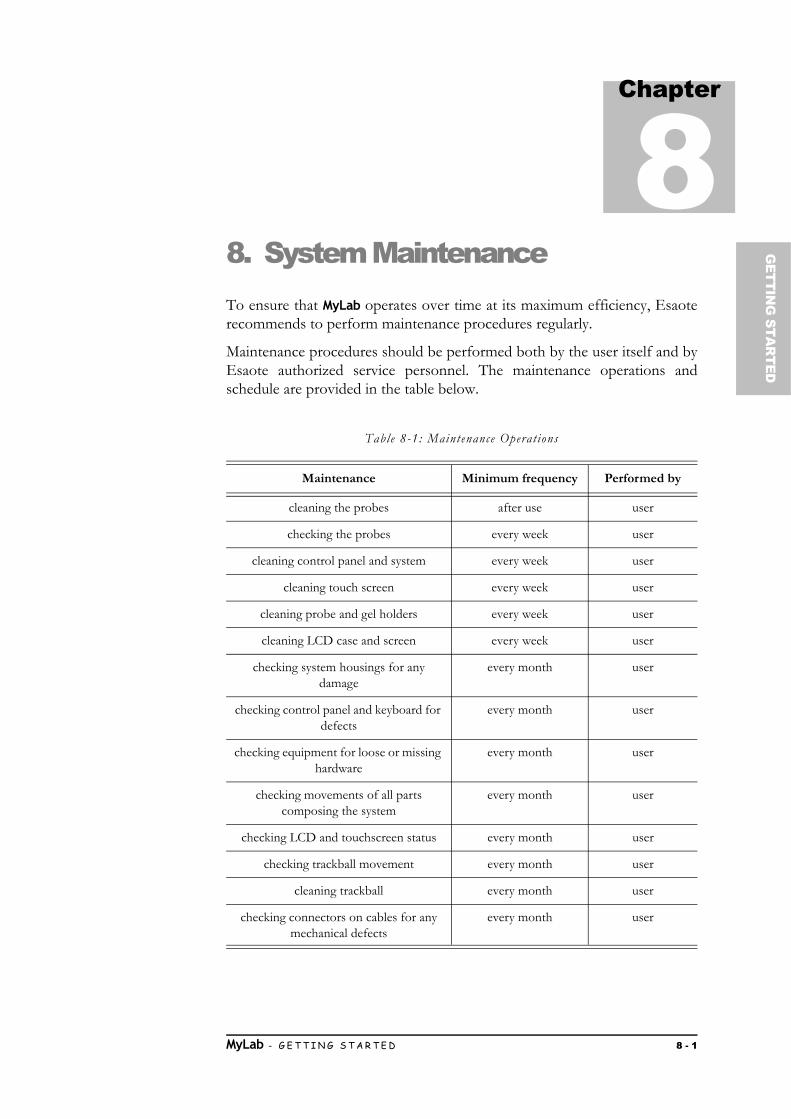
Chapter
8G
ETTING
STAR
TED
8. System MaintenanceTo ensure that MyLab operates over time at its maximum efficiency, Esaoterecommends to perform maintenance procedures regularly.
Maintenance procedures should be performed both by the user itself and byEsaote authorized service personnel. The maintenance operations andschedule are provided in the table below.
Table 8-1: Maintenance Operat ions
Maintenance Minimum frequency Performed by
cleaning the probes after use user
checking the probes every week user
cleaning control panel and system every week user
cleaning touch screen every week user
cleaning probe and gel holders every week user
cleaning LCD case and screen every week user
checking system housings for any damage
every month user
checking control panel and keyboard for defects
every month user
checking equipment for loose or missing hardware
every month user
checking movements of all parts composing the system
every month user
checking LCD and touchscreen status every month user
checking trackball movement every month user
cleaning trackball every month user
checking connectors on cables for any mechanical defects
every month user
MyLab - G E T T I N G S T A R T E D 8 - 1

S Y S T E M M A I N T E N A N C E
NOTE Frequency of cleaning can change depending on environment cleanliness.
NOTE Periodic maintenance operations that require the access to the system canbe performed only by trained personnel: contact your local Esaoterepresentative for further information on required periodic inspections.
Only trained persons are allowed to perform the safety inspection mentionedabove.
Disconnect the system from the power outlet before checking it.
Contact Esaote personnel for any problem found during inspection.
PC Refer to “Probes and Consumables” manual for periodic inspections forprobes and cleaning instructions.
Veterinary Applications
WARNING Due to the specificity of the veterinary working place, Esaote recommendsthat the ultrasound devices used in veterinary applications should bethoroughly cleaned at least once every 6 months. Please contact yourEsaote distributor or dealer for further help in this matter.
checking entire length of electrical and power cables for cuts or damages
every month user
checking the system integrity, functionality and cleaning (including
internal components)
every year Esaote personnel
Electrical Safety Tests every two years Esaote personnel or authorized
personnel
Maintenance Minimum frequency Performed by
MyLab - G E T T I N G S T A R T E D 8 - 2
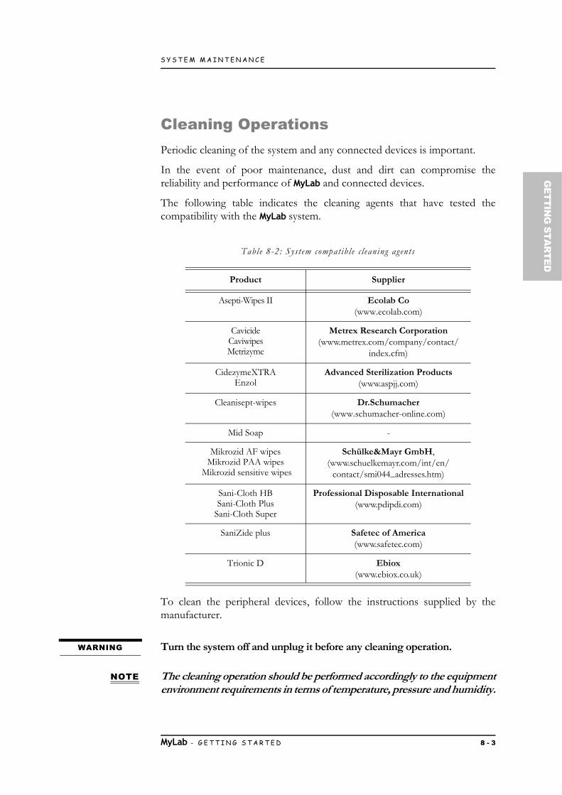
S Y S T E M M A I N T E N A N C E
GETTIN
G STA
RTED
Cleaning OperationsPeriodic cleaning of the system and any connected devices is important.
In the event of poor maintenance, dust and dirt can compromise thereliability and performance of MyLab and connected devices.
The following table indicates the cleaning agents that have tested thecompatibility with the MyLab system.
Table 8-2: System compatible c leaning agents
To clean the peripheral devices, follow the instructions supplied by themanufacturer.
WARNING Turn the system off and unplug it before any cleaning operation.
NOTE The cleaning operation should be performed accordingly to the equipmentenvironment requirements in terms of temperature, pressure and humidity.
Product Supplier
Asepti-Wipes II Ecolab Co (www.ecolab.com)
CavicideCaviwipesMetrizyme
Metrex Research Corporation (www.metrex.com/company/contact/
index.cfm)
CidezymeXTRAEnzol
Advanced Sterilization Products(www.aspjj.com)
Cleanisept-wipes Dr.Schumacher(www.schumacher-online.com)
Mid Soap -
Mikrozid AF wipesMikrozid PAA wipes
Mikrozid sensitive wipes
Schülke&Mayr GmbH, (www.schuelkemayr.com/int/en/
contact/smi044_adresses.htm)
Sani-Cloth HBSani-Cloth Plus
Sani-Cloth Super
Professional Disposable International(www.pdipdi.com)
SaniZide plus Safetec of America(www.safetec.com)
Trionic D Ebiox(www.ebiox.co.uk)
MyLab - G E T T I N G S T A R T E D 8 - 3
S Y S T E M M A I N T E N A N C E
Check the instructions supplied by the manufacturer of the cleaning agentsfor possible stricter limitation. Do not use hot cleaning agents for cleaningthe equipment.
CAUTION Apply the cleaning agents only for the time necessary to remove the dirtwithout exceeding over.
A visual inspection of the parts subjected to the cleaning process in order toevaluate possible damages or deteriorations.
Cleaning control panel and system
To clean the control panel and system, switch the MyLab off, unplug it and usea soft cloth slightly dampened with water.
If necessary use the suggested wipes, or a soft cloth slightly dampened withone of the suggested cleaning agents.
Otherwise, apply a small amount of ammonia-free and not abrasive detergenton a clean, soft cloth and then wipe the surface.
WARNING Make sure that the detergent has completely evaporated before turning theequipment on.
CAUTION Do not use any type of ammonia- or benzene-based cleaners on the case.
Cleaning the trackball
The trackball can be accessed, for cleaning purpose only, by rotatingcounterclockwise the upper locking disk.
Once the disk has been removed, clean the trackball using a soft dry cloth.Clean the trackball housing using a cotton swab.
CAUTION When cleaning the trackball housing, make sure not to spray any liquid intothe trackball housing.
Clean the ball rotating it in its socket. Do not remove the ball from the socket.
The X-series trackballs contain two 855 nm semiconductor lasers. The deviceis designed such that it fulfills laser safety class 1M regulations, according toIEC 60825-1 2007 2nd edition.
The laser radiation emitted is invisible to the human eye.
MyLab - G E T T I N G S T A R T E D 8 - 4

S Y S T E M M A I N T E N A N C E
GETTIN
G STA
RTED
WARNING Invisible laser radiation. Do not view directly with optical instruments.Class 1M laser products.
Do not remove the ball from the socket.
WARNING Do not try to disassemble the trackball during the cleaning of theremovable sealing ring.
Cleaning Probe and Gel Holders
Probe and gel holders are easily removable from their location for cleaningand can be washed in a mild soap solution. Make sure they are completely drybefore replacing them.
PC To clean the probes, refer to the manual “Probes and Consumables”.
Cleaning the Touchscreen
To clean the touchscreen, switch MyLab off, unplug it and use a soft dry cloth,lightly rubbing the display surface. To remove stains, lightly dampen the clothwith ethanol and water mixed in a 1:1 ratio and gently wipe the touch panelsurface; afterwards, dry the touch panel with a new dry cloth.
If strictly necessary, to clean the touchscreen during an examination, you cantemporarily lock the keyboard and the touchscreen pressing FREEZE whilekeeping ETOUCH pressed. When the system is on and connected to the mains,for safety reason, you must use only a soft dry cloth to clean the touchscreen.
WARNING Do not spray or apply the cleaning agents directly on the touchscreensurface as the liquid of the cleaning agents may permeate into the frontbezel of the display and cause damage.
Do not press the touchscreen with any sharp objects as this may damagethe screen.
When the system has not been unplugged, clean the touchscreenexclusively using a dry cloth. Never use wet cloth.
MyLab - G E T T I N G S T A R T E D 8 - 5

S Y S T E M M A I N T E N A N C E
Cleaning the LCD Screen
To clean the LCD use a soft dry cloth, lightly rubbing the display surface toremove dust and other particulate matter. If necessary, apply a small amountof ammonia- free glass cleaner onto a clean, soft cloth and then wipe thesurface.
Never spray or pour any liquid directly onto the screen or case.
WARNING Overspray or liquid may cause electrical shock.
Cleaning the LCD case
Use a soft, dry cloth to wipe the surface of the case. If necessary, apply a smallamount of ammonia-free and not abrasive detergent onto a clean, soft clothand then wipe the surface.
CAUTION Do not use any type of ammonia- or benzene-based cleaners on themonitor’s screen and case.
MyLab - G E T T I N G S T A R T E D 8 - 6

Chapter
9G
ETTING
STAR
TED
9. Technical SpecificationsThis chapter describes the technical specifications1 of the MyLab systems.
NOTE Special packages (such as Strain) are listed and described in the specificsections of the “Advanced Operations” manual.
MyLab CharacteristicsMyLab models differ in licences that are installed per default and licences thatcan be installed. The tables below list all the available licences regardless themodel on which they could be installed. Refer to the corresponding SalesArea manager for further information.
Licenses
Licenses enable specific functions of the system, they are linked to the systemserial number and are, therefore, unique. They should be carefully stored. Thesystem is delivered by Esaote, with the licenses already installed.
Additional features can be added buying the related license.
1. Specifications subject to change without notice. Information might refer to products or modalities not yet approved in all countries.
MyLab - G E T T I N G S T A R T E D 9 - 1

T E C H N I C A L S P E C I F I C A T I O N S
Applications MyLab systems can be equipped with the following application licenses.
Table 9-1: Applicat ion l i censes
System Features Depending on the model, MyLab can be configured with one or more of thefollowing features.
Table 9-2: System Features
Licence Application Features
General Imaging Abdominal Canine, Abdominal Feline, Abdominal Equine,
Abdominal Bovine, Abdominal (Other)
Presets, Calculations
Musc-Skel Tendon Equine Presets, Calculations
Reproduction Repro Canine,Repro Feline, Repro Equine, Repro
Bovine, Repro Ovine, Repro Porcine, Repro Caprine, Repro (Other)
Presets, Calculations
Cardiac Cardio Canine, Cardio Feline, Cardio Equine, Cardio Bovine, Cardio
(Other)
Presets, Calculations
Feature Description
3D/4D 3D and 4D Volumetric acquisition
3D/4D Advanced TPI, TMI and TSI modalitiesVRA analysis
Auto EF Automatically detects and tracks the left ventricle (LV) endocardial borders to calculate LV Volumes (Diastolic Volume, Systolic Volume) and EF (Ejection Fraction).
CMM Compass M-Mode allows to correct M-Mode line position to optimize tracing acquisition, even when the position of the
heart is not perpendicular to the ultrasound beam.
Dicom(including US Q/R)
DICOM Classesa
Ultrasound DICOM Query/Retrieve
Multi-modality & Dicom Q/R
Multi-modality managementMulti-modality DICOM Query/Retrieve
eStreaming Possibility to visualize the MyLab images on different devices on the same network
MyLab - G E T T I N G S T A R T E D 9 - 2

T E C H N I C A L S P E C I F I C A T I O N S
GETTIN
G STA
RTED
NOTE Features, probes and applications availability is dependent on your systemconfiguration. Not all features, probes and applications are approved in allCountries. Please refer to your Esaote local representative for furtherinformation.
MView It is an ultrasound technique which applies beam-line steering and acquires several coplanar scans of an organ from different
view angles.
MyLab Tablet Mobile application which allows to remotely review MyLab images on tablet or mobile
MyLibrary Dedicated libraries.Live Preview features allow to scan in real-time while using
anatomical references and scanning guidance.
Needle Enhancement Imaging
It increases the needle visibility.
Protocols Clinical protocolsb
Stress-Echo Stress-Echo allows to acquire multiple views of the left ventricle (LV) under stress, using customizable protocols.
TPView It enlarges the field-of-view.
TVM Tissue Velocity Mapping provides a complete Wall Motion Analysis for both systolic and diastolic myocardial function
evaluation.
VPan Panoramic Imaging merges multiple B-Mode images in one complete panoramic image.
XStrain XStrain allows to quantify endocardial velocities of contraction and relaxation and local deformation of the heart (Strain/
Strain Rate analysis).
XView XView enhances the pattern of every frame at the pixel level, eliminating speckle and noise artifacts.
a. Refer to www.esaote.com for further details on supported DICOM classes.b. Refer to the corresponding Sales Area manager for further information.
Feature Description
MyLab - G E T T I N G S T A R T E D 9 - 3

T E C H N I C A L S P E C I F I C A T I O N S
Technical CharacteristicsThis section describes the product when fully loaded with all options; refer tothe previous paragraph for basic configurations.
Display
Built-in color LCD, WVGA resolution
Full HD LED 21.5” monitor (16:9 aspect ratio)
8.9” LCD (touchscreen)
Probe connectors
3 electronic probes
Video Output
HDMI type 1
Connectivity
I/O connectors
• LAN RJ45• 2 USB 2.0 on keyboard control panel• 2 USB 3.0 on console left side• 1 USB for thermal printer• Wi-Fi (802.11 a, b, g, n)
Dedicated connectors
• ECG input
Other
• Laser/Ink jet printers
Complies with IHE integration profiles2
Image Files
Formats
• BMP (uncompressed)• PNG (lossless)
1. Auxiliary monitors connected to this input have not to be used for diagnostic purposes.
2. Refer to www.esaote.com for further details.
MyLab - G E T T I N G S T A R T E D 9 - 4
T E C H N I C A L S P E C I F I C A T I O N S
GETTIN
G STA
RTED
• JPEG (lossy)• AVI: Codec Microsoft MPEG-4 V2 and MS-Video 1• Native formats
Software
Operating system: Windows 10
Multi-lingual
Biometry
Basic and advanced calculation, application dependent
Annotations, bodymarks
Keyboard
Height adjustable control panel
Control panel:
• Potentiometers for TGC• Encoders for general gains• Keys for modes, peripherals management and controls
Reconfigurable touchscreen LCD
Dimensions
Closed: 490 (L) x 10001120 (H) x 600 (D) mm
In working position with gel and probe holders: 610 (L) x9201040 (H) x 600 (D) mm (height of trackball)
In working position with gel and probe holders: 610 (L) x13801500 (H) x 600 (D) mm (at top of the Monitor)
Weight
< 65 kg (basic configuration without peripheral units)
IP Grade
IP (X)0, this means MyLab models are not watertight.
MyLab - G E T T I N G S T A R T E D 9 - 5

T E C H N I C A L S P E C I F I C A T I O N S
Power supply
Voltage operative range:
• 100 120 V• 200 240 V
Working frequency range: 50 60 Hz ±10%
Power consumption: 220 VA (MyLab only)
Power consumption: 600 VA (MyLab + peripherals)
Available power on peripherals: up to 250 VA
Fuses: T 5Ah, 250 V (220V)/ T 10Ah, 250 V (110V), 5x20mm
Batteries
Batteries for:
• stand-by suspension• fast movement without switching off
Battery charger inside
Battery charging cycle: around three and a half hours (3 h 30min)
Battery life: 3 years
MyLab - G E T T I N G S T A R T E D 9 - 6

T E C H N I C A L S P E C I F I C A T I O N S
GETTIN
G STA
RTED
Power Cables
Table 9-3: Power Cables
Connector Plug Type Cord Type Length
ItalyChile
EN60320/C13 I/3G CEI 23-50 H05VVF3G
Section 1 mm2
3 conductors10A-250V
4,5 m
EUGermany
EN60320/C13 Type VII GCEE (7) VII
H05VVF3G
Section 1 mm2
3 conductors10A-250V
4,5 m
USANorth America
C13MEN60320/C13
HG (Hospital grade)NEMA 5-15
SJT3x14AWGSection AWG 14
3 conductors15A-125V
4,5 m
China EN60320/C13 PCR/3GB2099 / GB1002
H05VVF3G
Section 1 mm2
3 conductors10A-250V
4,5 m
Brazil EN60320/C13 BR/3according to NBR14136
H05VVF3G
Section 1 mm2
3 conductors10A-250V
4,5 m
UKSingapore
EN60320/C13 BS13/13BS 1363/A
H05VVF3G
Section 1 mm2
3 conductors10A-250V
4,5 m
Swiss EN60320/C13 12GSEV 1011-2009
SEV 6534/2
H05VVF3G
Section 1 mm2
3 conductors10A-250V
4,5 m
IsraelMiddle East
EN60320/C13 IL/3GSI32
H05VVF3G
Section 1 mm2
3 conductors10A-250V
4,5 m
AustraliaNew Zealand
EN60320/C13 SAA/3AS/NZS 3112-2000
H05VVF3G
Section 1 mm2
3 conductors10A-250V
4,5 m
MyLab - G E T T I N G S T A R T E D 9 - 7

T E C H N I C A L S P E C I F I C A T I O N S
Operating Requirements
Temperature: 15 35°C
Humidity: 15 85% (not condensing)
Pressure: 700 1060 hPa
Storage requirements
Temperature: -20 +60°C
Humidity: 10 85% (not condensing)
Pressure: 700 1060 hPa
Probe Storage Requirements
Probe storage requirements are indicated in the probe case.
Denmark EN60320/C13 DK3/HGASB 107-2D1 DK2-
8a
H05VVF3G
Section 1 mm2
3 conductors10A-250V
4,5 m
South AfricaIndia
Namibia
EN60320/C13 ZA/3SANS 164/1
IS 1292
H05VVF3G
Section 1 mm2
3 conductors10A-250V
4,5 m
Connector Plug Type Cord Type Length
MyLab - G E T T I N G S T A R T E D 9 - 8

T E C H N I C A L S P E C I F I C A T I O N S
GETTIN
G STA
RTED
Standards
Table 9-4: Standards
Standard Title
IEC 60601-1:2012 (Ed.3.1)EN 60601-1:2006 + CORR. 1 (2006) + CORR. 2 (2007) +
AMD. 1 (2015)
Medical electrical equipment - Part 1: General requirements for basic safety and essential
performance
CAN/CSA C22.2 No. 60601-1:08CAN/CSA C22.2 No. 60601-1.14
Medical Electrical Equipment - Part 1: General Requirements for Safety
ANSI/AAMI ES60601-1: 2005 + A2:2010
Medical Electrical Equipment - Part 1: General Requirements for Safety
IEC 60601-1-2:2014 (Ed.4)EN 60601-1-2:2015 (Ed.4)
Medical electrical equipment - Part 1-2: General requirements for safety - Collateral Standard:
Electromagnetic compatibility - Requirements and tests
IEC 60601-1-6:2010 + A1:2013 (Ed. 3.1)
EN 60601-1-6:2010 + A1:2015
Medical electrical equipment - Part 1-6: General requirements for basic safety and essential
performance – Collateral standard: Usability
IEC 60601-2-37:2007 (Ed. 2.1) + A1:2015
EN 60601-2-37:2008
Medical electrical equipment - Part 2-37: Particular requirements for the basic safety and essential
performance of ultrasonic medical diagnostic and monitoring equipment
IEC 61157:2007 (Ed. 2.1) +A1:2013
Standard means for the reporting of the acoustic output of medical diagnostic ultrasonic equipment
IEC 62304EN 62304
Medical device software - Software life cycle processes
IEC 62366:2007 + A1:2014 (Ed. 1.1)
EN 62366:2008
Application of Usability Engineering to Medical Devices
EN ISO 10993-1:2009 Biological evaluation of medical devices - Evaluation and testing
EN ISO 14971:2012 Medical equipment - Application of risk management to medical devices.
ISO 15223-1 Medical devices - Symbols to be used with medical device labels, labeling and information to be
supplied - Part 1: General Requirements
AIUM/NEMA UD-2:2004 (R2009)
Acoustic Output Measurement Standard for Diagnostic Ultrasound Equipment.
MyLab - G E T T I N G S T A R T E D 9 - 9

T E C H N I C A L S P E C I F I C A T I O N S
AIUM/NEMA UD-3:2004 (R2009)
Standard for Real Time Display of Thermal and Mechanical Acoustic Output Indices on Diagnostic
Ultrasound Equipment.
CAN/CSA C22.2 NO. 60601-2-37 Medical electrical equipment - Part 2-37: Particular requirements for the basic safety and essential
performance of ultrasonic medical diagnostic and monitoring equipment
Standard Title
MyLab - G E T T I N G S T A R T E D 9 - 10