www. · pdf filewww. hparchive.com please visit us on the web ! on-line curator: glenn robb...
TRANSCRIPT

HP Archive
This vintage Hewlett Packard document was preserved and distributed by
www. hparchive.com Please visit us on the web !
On-line curator: Glenn Robb
This document is for FREE distribution only!

INSTRUCTION AND OPERATING MANUAL
FOR
MODEL 500A
ELECTRONICFREQUENCY METER
Serial 2315 and Above
APLIED PHYSICS STAF,
'lUDN"'\TIO AND CERTIFICATIO GROUP
COpy · DO NOT REMOVE FROMORV
HEWLETT-PACKARD COMPANY
395 PAGE MILL ROAD. PALO ALTO. CALIFORNIA. UoS. A.

General Description
The Model 500A Frequency Meter directly measures the frequency of analternating current voltage from 5 to 50, 000 cycles/sec. It will operate withthe input voltage as low as .5 volts. Variation of the input voltage from. 5 to200 volts or variation of line voltage from 105 to 125 volts has very little effecton the accuracy of the instrument.
This instrument is useful for measuring the beat frequency between tworadio frequency signals, crystal frequency deviation, audio frequencies, andfor measuring the speed of rotating machinery when used in conjunction with aphoto tube and a light source.
CAUTION
THE MAXIMUM VOLTAGE APPLIED TO THE INPUT TERMINALS OF THIS
INSTRUMENT MUST NOT EXCEED 600 VOLTS, THE SUM OF THE DC VOLTAGE
AND THE AC PEAK VOLT AGE. HIGHER VOLT AGES WILL BREAK DOWN THE
CAPACITOR IN THE INPUT CIRCUIT OF THIS INSTRUMENT.
Parts Substitutions
Difficulties in procuring some of the parts used in this instrument maycause the electrical or physical values to deviate from those shown in this instruction manual. These substitutions have been made so as not to impair theperformance of this instrument. Whenever replacement of any of these partsis necessary, either the substitute value or the original value may be used.
ucc~

..
~:> •o
~.,l:j
\.()
~
r.-4
......til....I-<~
U)
INSTRUCTIONS
MODEL 500A
ELECTRONIC FREQUENCY METER
Specifications
Frequency Rating --
Range- 10 to 50,000 cycles/sec o in ten ranges.
Full Scale Indication - 50, 100, 200, and 500 cycles/sec.1, 2, 5, 10, 20, and 50 KC/sec.
Input Voltage --
Minimum Input Voltage- 05 volts Variation of the input voltage from05 to 200 volts will affect the meter indication not more than ±1 %.
Input Impedance --
Approximately 300, 000 ohms shunted by 37 1J.1J.f.
Accuracy --
±2% of full scale.
Voltage Stability --
Power line voltage variations from 105 to 125 volts will affect themeter indication less than ±1% .
Recorder Output Characteristics
Current - 1 mao
Resistance - 1400 ohms ±100 ohms
Power Supply Rating --
Voltage - 105 to 125 volts/210 to 250 voltsFrequency - 50/60 cycles/sec.Wattage - 65 watts
Overall Dimensions --
Cabinet Model - 19" wide x 8-1/2" high x 11 -1/2" deep
Rack Model - 19" wide x 8-3/4 11 high X 11-1/2" deepPanel Size - 19 11 x 8-3/4"Depth Behind Panel - 10-1/2 1
'
-1-
Weight --
Cabinet Model - 20 lbs.Rack Model - 20 lbs.
Operating Instructions
Inspection --
This instrument has been thoroughly tes ted and inspected before beingshipped and is ready for us e when received.
After the instrument is unpacked, the instrument should be carefully inspected for damage received in transit. If any shipping damage is found, followthe procedure outlined in the "Claim for Damage in Shipment" page at the backof this ins truction book.
Controls and Terminals
INPUT - These binding posts are connected to the input circuit of thefrequency meter. The binding post marked G is connected to the chassis.
CAUTION
THE MAXIMUM VOLTAGE APPLIED TO THE INPUT TERMINALS OF THIS
INSTRUMENT MUST NOT EXCEED 600 VOLTS, THE SUM OF THE DC VOLT AGE
AND THE AC PEAK VOLT AGE. HIGHER VOLT AGES WILL BREAK DOWN THE
CAPACITOR IN THE INPUT CIRCUIT OF THIS INSTRUMENT.
TEST - This switch is provided for testing the input voltage level todetermine if it is adequate to operate the instrument.
PHOTOTUBE - This jack is provided for connecting a phototube to theinstrument to' convert the instrument to an electronic tachometer. When theplug is inserted in this jack, the input circuit is changed to match the characteristics of a type lP4l phototube.
USE-LINE FREQ - CALIBRATE - This switch is used to connect theindicating meter and input ClTcuit to perform several functions. The switchposi tion and corresponding functions are listed below.
\Jtoo>
Switch Position
USE
LINE FREQ.
-2-
Function
The meter is connected toindicate frequency and theINPUT terminals are connectedto the input of the amplifier.
The meter is connected toindicate frequency. The 6.3 V.

CALIBRATE
secondary of the power
transformer is connected
acros s the input of the
amplifier in order to measure
the power line frequency as a
check on the instrumentcalibration.
The meter is connected as a
DC milliameter to measure the
current drawn by the switching
tubes (V4,. V5). The current
is adjusted so that the meter
pointer coincides with the
calibration mark on the meter
scale. The amplifier input
is short circuited when the
switch is in this position.
RANGE _ This switch is used to insert the correct coupling capacitors and
meter shunt resistors in the circuit for any desired range of frequency measure
ment.
CALIBRATE - This control is used to adjust the current drawn by the
switching tubes.
RECORDER - The RECORDER jack is provi ded for connecting a recorder
to the instrument. This instrument is designed to drive an Easterline - Angus
Automatic Recorder. However, other recorders may be substituted if their
resistance is 1400 ohms ±100 ohms and a full scale indication can be obtained
with a current of one milliampere.
ON - OFF - This toggle switch controls all the power supplied to the
instrument from the power line.
FUSE - The fuseholder, located on the back of the instrument, contains
a 1 ampere cartridge fuse. To replace the fuse, unscrew the fuseholder cap and
remove the blown fuse, insert a new fuse of the same type and replace the fuse
holder cap. For 230 volt operation this fuse should have a 1/2 ampere rating.
Replacement fuses must be of the "Slo-Blo" type as specified in the Table of
Replaceable Parts in this instruction manual.
Power Cable - This is a special three conductor power cable with a
standard two prong male plug molded on one end. The third conductor (green)
protrudes from the power cable near the plug and may be used to connect the
instrument chassis to an external ground.
-3-

Operation --
The procedure for me asuring frequency is as follows:
1. Turn the power switch to ON and allow the instrume nt to warm up fortwo or three minutes. If maximum accuracy is desired, me asurements shouldnot be made until the instrument is completely warmed up.
2. Set the USE-LINE FREQ. -CALIBRATE switch to the CALIBRATEposi tion. Adjust he CALIBRATE control so that the me ter pointer coincideswith the meter scale division labeled "C" - located at approximately 85 on the0-100 meter scale. This step in the procedure calibrates the instrument. Thecalibration should be rechecked occasionally while making measurements.
3. Set the RANGE switch to the 100~ range. Change the USE-LINEFREQ. -CALIBRATE switch to the LINE FREQ. position. The frequency of thepower line voltage is indicated by the meter. This measurement serves as acheck on the calibration of the ins trmnent.
CAUTION
No external voltage should be applied to the lOput terminals when thepower line frequency is being measured. Application of external voltage maycause inaccurate line frequency measurements.
4. Change the USE-LINE FREQ. -CALIBRATE switch to the USE position and apply the voltage to be measured to the INPUT terminals. Set theRANGE switch to cover the frequency being measured. If the approximatefrequency is unknown, turn the RANGE switch to the highest frequency range.Change the switch to successively lower ranges until a range is found that produces a readable meter indication.
5. While the meter is indicating the frequency being measured, depressand hold in the TEST button. If the meter indication is unchanged by this test,then there is sufficient input voltage for the instrument to produce an accuratefrequency measureme'nt'. Insufficient input voltage, as shown by a loweredmeter indication when the TEST button is pressed, will cause inaccurate frequency measurements.
Attaching a Recorder to he Model 500A -
When a recorder is used with the Model 500A, it is neces sary that thecompensating resistor in the instrument be adjusted so that the resistance ofthe recorder matches the instrument.
This adjustment is made as follows:
1. Warm up the instrument and measure either the power line frequencyor the frequency of an audio os cillator. Note the frequency indicated by the meter.
-4-
•
\J1oo
':X:-
Ct:l(1)
~.III.....
n-o

l.C)
--Dr............cd....MQ)
U)
2. Plug the lead from the recorder into the RECORDER jack. If themeter (MI) indication is not the same as noted in step I, adjust R56 (See Fig.4) so as to produce the same indication as in step 1. When the recorder is disconnected from the RECORDER jack, resistor R56 is removed from the circuitand R53 substituted so that the accuracy of the Model 500A is not impaired.
Using the Model 500A as a Tachometer -
The Model 500A may be employed as a tachometer by connecting a suitable phototube to the instrument. A source of light to be reflected into the phototube, by a target painted on the rotating machinery being measured, must alsobe provided.
The above mentioned phototube and light source have been combined intoone assembly and may be purchased from the Hewlett-Packard Co. This accessory is called a Model 506A Tachometer Head Assembly.
Zero Meter Indication - T~'le meter pointer may not coincide with the zeroscale rllar~< when t~'le instrument 1S not oFerating. The meter pointer is correctlyadjusted a:'ld the adjustment screw sealed at the factory.
-5-

Circuit Description
The Model 500A Electronic Frequency Meter consists of a limiting amplifier, an electronic switchi g circuit, a pulse counter circuit, a constant current regula or and a power supply.
A voltage of unknown frequency is applied to the limiting amplifier, tubesVI, V2, V3. Tubes VI and V2 amplify and flatten the peaks of the incomingvoltage. Tube V3 is a phas e inverter.
The square wave obtained from the plate circuits of tubes V2 and V3 isapplied to the switching circuit who ch is com.pos ed of tubes V4 and V5.
The space current for the two switching tubes is obtained from the constant current regulator. Alternate half cycles of the square wave causes all ofthe constant current to flow thlough tube V4 and charge one of the capacitorsC9-CI8. During the i tervening half cycles the constant current flows throughV5 and causes one of the capa 1tors C19-C28 to be charged. The time constantsof the two RC combinations R33, C9-C18 and R32, C19-C28 are equal. The resistor and capacitor values are such that, at the highest frequency to be counted,the capacitors will be fully charged before the end of the half cycle. The accurately controlled pulses from the capacitors C9 -C18 and C 19 -C28 are convertedto unidirectional pulses by the crystal rectifiers CRI-CR4 and the resultantcurrent is ind1cated by meter Ml. The meter ·ndi ation is proportional to thenumber of puIs es per unit of time and therefore to the frequency of the voltageapplied to the input of the instrument. The resistors R34 to R43 are shuntsacross the meter to adjust the current through the meter to the correct valuefor each frequency range.
Res1stors R55 and R56 are adjusted to match the resistance of the recorder. They are automatically connected in series with the meter to compensate for the res1stance of the recorder when the recorder is not connected tothe lnstrument.
The constant current regulat.or consists of tubes V7, V8. Tube VB is avoltage regulator tube which maintalns a constant voltage on the screen grid oftube V7. A vol age dlvider R48, R49, R50 is connected between the screen gridand ground. The variable resistor (R49 on th1S d1vider is provided so that thevoltage applied to the grid of V7 may be adjusted to produce the desired constant current for the swltch·ng tubes This current is measured by switchingthe mete (M 1) acros the shunt resistor R2 7. This resistor 1S inserted in theplate Circuit of tube V7.
-6-
U1oo:>
n-o

·.
IRE
CO
RD
ERI
11
5/2
30
V5
0/6
0ru
TU
BE
V6
PO
WE
RS
UP
PLY
.--~-
TU
BE
SV
7,
VBI
tI
L--
--I-
----
----
fI
It
•I
r-J
CO
NS
TA
NT
CU
RR
EN
TR
EG
ULA
TO
R
PU
LSE
CO
UN
TE
RE
LE
CT
RO
NIC
CIR
CU
ITL
IMIT
ING
AM
PL
IFIE
RS
WIT
CH
C9
-C
2B
j ,T
UB
ES
VI,
V2
,V
3r-
TU
BE
Sv4
,V
5R
EC
TIF
IER
SC
R1
-C
R4
JI
II
IvI
v~
--
o IPH
OT
OT
UB
EI
IINP
UTI
Fig
.1
.M
od
el
50
0A
Blo
ck
Dia
gra
m

o...,
.....'"......J.l(l)
U)
-ex:oot{)
, ,
Maintenance
Cover and Bottom Plate Removal -=
The bottom plate is removed by unscrewing the four screws, one in eachcorner of the bottom plate. which fasten the plate to the chassis.
The cover is removed by unscrewing the eight screws which fasten thecover to the ba k and top of the instrument.
Tube Replacement --
Any tube having RTMA standard haracteristics may be used for replacement purposes in this instrument.
Hum Balance Adjustment (R55) --
The adjustmen of the variable resistor for balancing out the unwanted60~ current is as follows:
1. Measure and note the power line frequency. Shield the INPUT terminals of the instrument. A shielded double banana plug is satisfactory.
2. Set the USE-LINE FREQ. -CALIBRATE switch to USE and the RANGEswitch to the 50~ position.
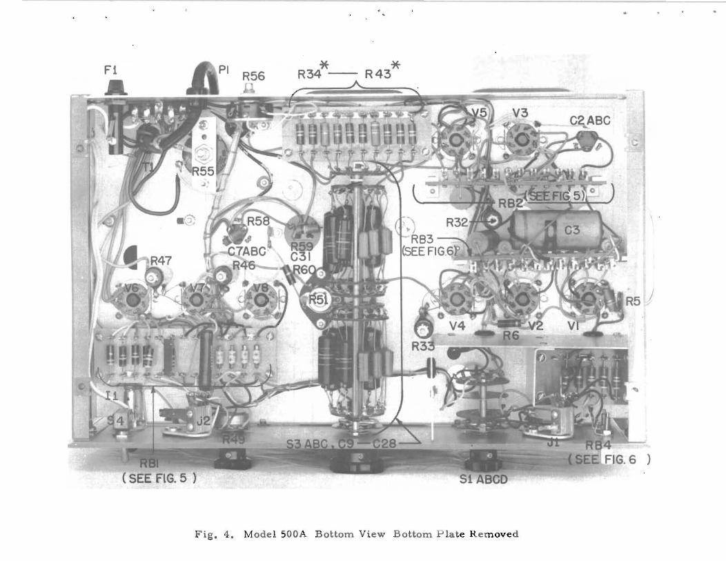
3. Adjust R55, located underneath the chassis and reached by removingthe bottom plate (See Fig. 4), for minimum meter (Ml indication .
4. Measure the line frequency and compare with previous line frequencymeasurement. If they are not the same, re-adjust R55 slightly to one side sothat the line frequency is correct.
Frequency Calibration Adjustment
The only calibration adjustment that should be performed in the field isthe adjus tment of the meter shunt resis tor s R34 to R43. If any of the couplingcapaci ors C9 to C28 are affecting the calibration, the instrument should be returned to he factory for adjustment.
The procedure for adjusting the shunt resistors is as follows:
1. _ Warm up the ins trument and set the controls for frequency measurement.
2. Starting with the RANGE switch at the 50~ position, apply a 50~
voltage to the INPUT terminals of the instrument. This voltage should be obtained from a secondary frequency standard or some other source of accuratefrequencies. If the meter does not indica e exactly full scale, then adjust thevalue of the shunt resistor R34 by substituting another resistor or by connecting a h' gh resistance ln parallel wi th R34.
-7-

3. Repeat step 2 for 1001\" 2001\, and etc. using a calibration voltage whosefrequency is equal to the full scale frequency of each range. Adjust the shuntresistor which corresponds to the range being calibrated.
Adjus
The pro edure for adjus ing he onstan current regulator circuit is asfollows:
1. Warm up the ins rumen using U5V line vol age. Set the USE-LINEFREQ. -CALIBRATE SWl ch 0 CALIBRATE. Adjust the CALIBRATE control sohat the me er indica es exactly 80 on the 0 0 100 scale.
2. Change the line voltage to 105 vol s and note the meter indi ation.Repea a 125 vol s line vol age. If he me er indication does no change morethan ±l% of full scale (80.5 to 79.5). en the regulator circuit is functionings atisfactorl1y.
3. If he meter indicatlOn is ot within he specified'limi s. then a newOD3 tube V8) and/or a new 6L6 tube (V7) should be tried. The OD3 ube shouldbe aged by operating it for eigh hours Wl h 150 volts applied across i s terminals. The easiest way 0 age the ube is 0 pu it in its socket in the instrumentand let the instrument opera e for eigh hours.
If changing tubes does not res ore he regulator circuit to normal. thenadditional adjus men s will be necessary.
4. With he line voltage at 115 olts. set the USE-LINE FREQ. -CALIBRATE swit h at CALIBRATE. Se the CALIBRATE con rol to produce a me erindica ion 0 80. hen hange he USE---CALIBRATE switch 0 USE and apply a50,000 cycles/sec. voltage 0 the INPUT terminals. No e he me er indication.
5. Adjust R6l. (See Resis or Board Detail RBI, Fig. 5) by conne ting aresis or in parallel wi h R6l or by substitu ing a new resistor of higher value,so tha the me er does no vary more han ±l% of full scale when the power linevoltage is varied from 105 to 125 vol s.
U"loo>
'm, ~.•
"t....III..........-J0'U"l
6. Withoutand inpu frequencypower line vol age.variations from heless, he circuit is
hanging he CALIBRATE con raj. change the RANGE switcho 1000 cycles/sec. Note th me er indication with 115 voltsChange power Ii e voltage to 105 and 125 volts and note any
indica io obtained at 115 volts. If the variation is ± 1% ororrec ly adjusted.
However. if he varia ion is m re han ±1% then the value of R61 shouldbe changed so as 0 ob ain the bes compromise between the 1000 and 50.000cycles/sec. adjustmen s.
-8-

•
R3
4*
,C
Rl
1·u
co3
}<:.,
51
05
30
IOAN
GE!
1.~
'.(5
0",1
2.
ILIN
EF
RE
Q.!
2.
11
00
"\1
1
3.
ICA
LIB
RA
TEI
3.
!zoo
-vi
4.
!50
0'"
I5
.E
:TIJ
6.
II!I
J7
.rr:
m8
.l:I
§:ill
9.
(1Ii
ll
10.~
03
5·
\!F
G.9
53
C..'
53
A
53
B
G9
[fr'2
~G'O
.1u.
F t..
,l~ ~t-"
50
00
@--1
(--<
G'5
~r-
~.~
G'8
200
[fr'2~ G
20 ..~
,f2t
riG
23<!>
~Ol
JlF
r--1
(.
I®
C'2
45
00
0@
-l{-
....G
25
<L;~
19y~
50
0
G28~
200 ~
03
35
00
0
03
25
00
0
~
.r--
-®Q
)--
R4
3I
r®er
-"42
·1.fJ
J6~
I;;'O
YO·
R4
1l
•<:R
31•
040'~"
39'0
38
J~.~jj~~~~
I
"''
'1$
"28~
'00
K
,.2
40
:.::
45
_
V5
3'-
'60
6V
6V4
~6~6
+J6
0
"51
22
K,
===
4
R29
"\
82
20
1<
1'21
$
G4
.qJ
.FII
..L
G5
""T
'"".
IIJ.F
R5
21
00
0
[f5~
1
~G8
T5
0,l
lF
+4
00
"2
71
00
"'B
.5K
02
64
70
II(
02
05
6K h=
i'~056
30
0
..L
C2
C""
"",O
IiF
04
75
00
0
~_fIm
RE
CO
RD
ER
•M
A
J2~_
""0
0
04
85
3K
04
9
>:5K1
1"'"
·O~1+6"
1/6
0
va DD
3
V2
65
J7
"4
610
K
04
5~
1001
<
•"06
11
00
I<2
0'5
27
0K
0'4
10
0K
G7
B20
j,lF
..
00
G3
.5jl
F
-1(-
~ C7
A2
0Jl.
F
,f4
0
IO
T>56
K
Vl
65
H
05
8'O
OK
R~9..LC31
fOO
+<
1""2
0jJ.
F
"''''0
t---
!!.2!
!.i.:.
CO
ND
ITIO
NS
OF
DC
VO
LTA
GE
ME
AS
UR
EM
EN
T
I.L
INE
VO
LTA
GE
,1
15
-23
0V
OL
TS
,5
0-6
0'\
1.
2.C
ALI
BR
ATE
THE
INS
TR
UM
EN
T.
3.
RA
NG
ES
WIT
CH
ON
10
0'\
...
4fU
NC
TIO
NS
ELE
CTO
RO
N1
INE
fRE
QU
EN
CY
.~
NO
EX
TE
RN
AL
CO
NN
EC
TiO
NS
TOTH
EIN
ST
RU
ME
NT
.6
VO
LTA
GE
SM
EA
SU
RE
DB
ETW
EE
NIN
DIC
AT
ED
PO
INTS
8C
HA
SS
lSW
ITH
AV
AC
UU
MTU
BE
VO
LTM
ETE
RW
ITH
122
ME
GO
HM
SIN
PU
TR
ES
ISTA
NC
E(H
PM
OD
EL
41
08
1.
CO
ND
1TIO
NS
OF
AC
VO
LTA
GE
ME
AS
UR
EM
EN
T1.
THR
U5
.S
AM
EA
SD
CC
ON
DIT
ION
S.
6V
OLT
AG
ES
tolE
ASU
RED
BE
TWE
EN
IND
ICA
TED
PO
INTS
WtT
HAN
AC
ME
TER
Of
10
00
OH
MS
IVO
LTO
RG
RE
ATE
RS
EN
SIT
IVIT
Y.
ALL
CA
PA
CIT
AN
CE
VA
LUE
SIN
IJ.J
JFU
NLE
SS
OTH
ER
WIS
EN
OT
ED
.
ALL
RE
SIS
TAN
CE
VA
LUE
SIN
OH
MS
UN
LE
SS
OTH
ER
WIS
EN
OT
ED
.
II<
•1
00
0O
HM
S,
IM
a1
ME
GO
HM
it~
AD
JUS
TE
DA
TFA
CTO
RY
FOR
OP
TIM
UM
PE
RfO
RM
·
-::h-
•C
HA
SS
ISA
NC
E.
AV
ER
AG
EV
ALU
ES
HO
WN
PA
RT
MA
YB
E-
OM
tTT
ED
.
05
12
0K
2-,
"24
;.~O
MI
"25
'5K
33
K"23 270
1<
"12
"5
41
5K
56
K7
1~
~G
6.1
~F
>V
3~V
7I
>V
l>
V2
<
oIT
mI
~52~
03
47
0I(
G'
.qJ
.F
J6!::OW
NfV4
~V5
BR
OW
N7
2
EI~
~'K
II
I 01
7I
0.9
22
<2
2K
33
K
10
1[
~040
7~
I~R16
41
0K
47
0It:
6.B
M5
60
56
0
02
2-l
.-G
2B
"6
II
56
0
10
00
TtO
IJ.F
51
AQ
}-
y.... -<D
L1-1
BR
OW
NT
,
PR
I.'"
1
23
0V
50
-60
'"B
LUE ~
PRI.
2
WH
ITE
DE
TA
IL
61IN
PU
TI
0<
[PH
OTO
TUBE
I
ION
-OF
F!
!FU
SE
!
054"?~
PI/
"--.
L'\
SEE
TRA
NS
DET
AIL
=--
r-
I
SC
HE
MA
TIC
DIA
GR
AM
OF
MO
DE
LS
ER
IAL
2315
aA
BO
VE
.50
0A

.N.00....
t:..

Fl
~ C7
\<'~
t~
.. Ll
";"
R5
6
b
"'~
\,ii
--
cO
"C3
1~.
V~'6SJ7
V4
6v6
(.,~.
r,'"
{~
VI-
6S
J7
C2A
BC
{
Fig
.3
.T
vfod
el5
00
AT
op
Vie
wC
ov
er
Rem
ov
ed
R56 .
*R
34--
*R
43
)
Fig
.4
.M
od
el5
00
AB
ott
om
Vie
wB
ott
om
Pla
teR
em
ov
ed

r-(OPP.SIDE)
+!
(OPP. SIDE)
RBI
(OPP. SIDE)
4 R22r 22K
(OPP. SIDE)
C5 J.1 J.lF
o
o
C6.1.uF
o
o
RB2
Fig. 5. Model500A Resistor Board Detail

,
o
o
,---------(0 pr. 51 OE}---·--·------l
~--ft-...,C3.5UF
RB3
o
-
C 1 (OPP. SIDE)
RB4
Fig. 6. Model SOOA Resistor Board Detail

,
TAB L E OF REP L ACE A B L EPA R T S
CircuitRef.
Cl
C2
C3
C4, C5,C6
C7 AB
C8
Description
Capacitor: fixed..! paper,o 1 ~f7 ±100/0s 600 vdcw
Capacitor: fixedg electrolytic,10~ 10, 10 ~f, 450 vdcw
Capacitor: fixed,' paper,. 5 ~f, ±100/0, 400 vdcw
Capacitor: fixed, paper,. 1 ~fg ±100/0, 600 vdcw
Capacitor: fixed, electrolytic,20, 20 ~f. 450 vdcw
Capacitor: fixed. electrolytic,50 ~f, +200%. -10%, 50 vdcw
-hpStock No.
16-1
18-31
16-58
16-1
18-22
18-50
Mf:r. * & Mfr s .Designation
CC#73P 10496
XFPT-389
CC#4TM-P5
CC#73P 10496
AAEF - I11X3"
C9 - C28 . '. Part of Range Switch Assembly
o...,
C29, C30
C3l
R4
R5
R6
R7
R8
R9
RIO
R11
Capacitor: fixed, paper,.Ol~, ±10%. 600 vdcw
Capacitor: fixed,. electrolytic,20 ~f, 450 vdcw
Resistor: fixed, composition,470.000 ohms, ±10%, 1 W
Resistor: fixed, composition,6.8 megohms, ±10%, 1 W
Resistor: fixed, compositicn,120,000 ohms, ±lO%g 1 W
Resistor: fixed, composition,1000 ohms, ±100/0, 1 W
Resistor: fixed, composition,560 ohms. ±10%, 1 W
Resistor: fixed, composition,1. 8 megohms, ±lO%, 1 W
Resistor: fixed, composition,22, 000 ohms, ±100/0. 1 W
Resistor: fixed. composition,3.9 megohms, ±10%, 1 W
Resistor: fixed. composition,33.000 ohms, ±10%, 1 W
16-11
18-20
24-470K
24-6.8M
24-120K
24-1000
24-560
24-1. 8M
24-22K
24-3.9M
24-33K
AType p688
XFPS-144
BGB 4741
BGB 6851
BGB 1241
BGB 1021
BGB 5611
BGB 1. 851
BGB 2231
BGB 3.951
BGB 3331
*See "List of Manufacturers Code Letters For Replaceable Parts Table."-10-
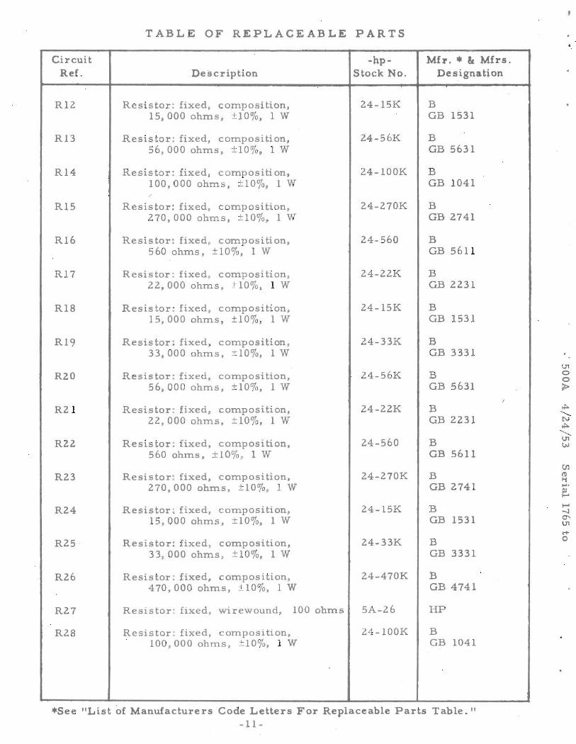
TABLE OF REPLACEABLE PARTS
Circuit -hp- Mh.• Ie Mfrs.Ref. Description Stock No. Designation
R12 Resistor: fixed, COInposition, 24-15K B15,000 ohm.s, ±10%, 1W GB 1531
R13 Resistor: fixed, cOInposition, 24-56K B56, 000 ohIns, ±10%, lW GB 5631
R14 Resistor: fixed, Co.m.positi on, 24-100K B100,000 ohIns, ±10%, 1 W GB 1041,.
R15 Resistor: fixed, COInposition, 24-270K B270,000 ohIns, ±10%, 1W GB ~741
R16 Resistor: fixed, co:rn.position, 24-560 B560 ohtns, ±10%, lW GB 5611
R17 Resistor: fixed, co.m.posi tion, 24-22K B22,000 ohIns, ±10%, lW GB 2231
R18 Resistor: fixed, co.m.posi tion, 24-15K B15, 000 ohIns, ±10%, lW GB 1531
R19 Resistor: fixed, COInposition, 24-33K B33, 000 ohIns ±10%, 1W GB 3331
R20 Resistor: fixed, cOInposition, 24-56K B56,000 ohIns, ±10%, lW GB 5631
I
R21 Resistor: fixed, co.m.position, 24-22K B22, 000 ohIns, ±10%, 1W GB 2231
RZ2 Resistor: fixed, composition, 24-s60 BS60 ohIns, ±10%, 1W GB 5611
R23 Resistor: fixed, co.m.position, 24-270K B270,000 ohms, ±10%, 1 W GB 2741
R24 Resistor: fixed, cOInposition, 24-lSK BlS,OOO ohIns, ±10%, lW GB 1531
R25 Resistor: fixed, co.m.position, 24-33K B33,000 ohms, ±10%, 1W GB 3331
R26 Resistor: fixed, co.m.position, 24-470K B470,000 ohms, ±10%, lW GB 4741
R27 Resistor: flxed, w1rewound, 100 ohms SA-26 HP
R28 Resistor: fixed, composition, 24-100K B100,000 ohIns. ±10%, 1 W GB 1041
*See "List of Manufacturers Code Letters For Replaceable Parts Table."-11-
\.11oo>
....o
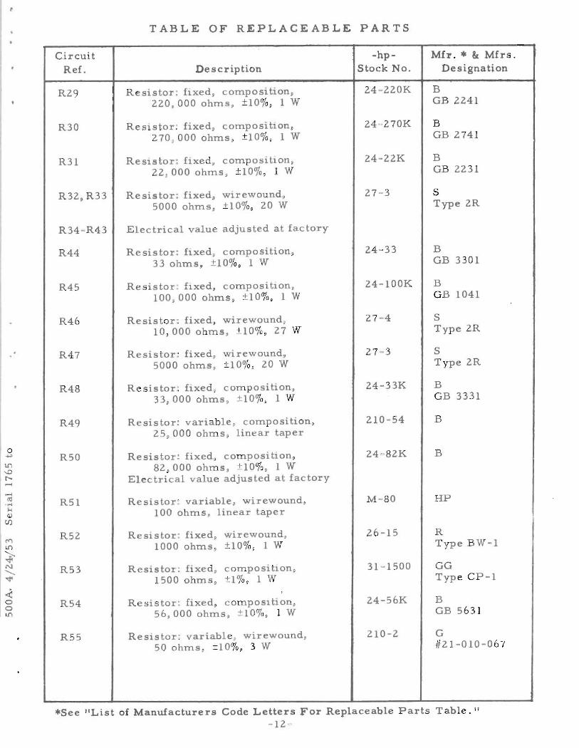
TABLE OF REPLACEABLE PARTS•
o....,
CircuitRef.
R29
R30
R31
R32 pR33
R34-R43
R44
R45
R46
R47
R48
R49
R50
R51
R52
R53
R54
R55
Description
Resis or: flxed p compositionp220,000 ohms p ±10%p 1 W
Resistor: fixedp composibonp270 p000 ohms p ±10%p 1 W
Resistor: ftxedp composibon,22 p000 ohms, ±10%p 1 W
Resistor: fixed. wirewound,5000 ohms, ±10%p 20 W
Electrical value adjusted a factory
Resistor: ftxed, composition,33 ohms, ±10%. 1 W
Resistor: flxed, composibon,100,000 ohms p ±10%p 1 W
Resistor: fixed, wirewoundp10,000 ohms, ±10%, 27 W
Resistor: fixed, wirewoundp5000 ohms p ±10%, 20 W
Resistor: ftxed, composition,33,000 ohms, ±10%, 1 W
Resistor: variable, composition,25,000 ohms p linear taper
Resistor: fixed p compositionp82,000 ohms p ±10%, 1 W
Electrical value adjusted at factory
Resistor: variable, wirewound,100 ohms, linear taper
Resistor: fixed, wirewound,1000 ohms p ±10%, 1 W
Resistor: fixed, compositionp1500 ohms. ±1%, 1 W
Resisto : fixedp compositionp56,000 ohms p ±10%, 1 W
ReSistor: variable. wirewound,50 ohms, ±10%p 3 W
-hpStock No.
24-22K
27=3
24-33
24-100K
27-4
27-3
24-33K
210-54
24-82K
M-80
26-15
31-1500
24-56K
210-2
Mh.• at Mfrs.Designation
BGB 2241
BGB 2741
BGB 2231
SType 2R
BGB 3301
BGB 1041
SType 2R
SType 2R
BGB 3331
B
B
HP
RType BW-l
GGType CP-1
BGB 5631
G#21-010-067
*See "List of Manufacturers Code Letters For Replaceable Parts Table. II
-12=

TABLE OF REPLACEABLE PARTS •
CircuitRef.
R56
Description
Resistor: variable, wirewound.300 ohms, linear taper
-hpStock No.
210-53
Mh.• & Mfrs.Designation
G#21-010-358
R57 Electrical value adjusted at factory
R58, R59
R60, R61
Resistor: fixed, composition,100,000 ohms, ±10%, 1 W
Resistor: fixed" composition,100,000 ohms, ±10%. 1 W
Electrical value adjusted at factory
Binding Post:
24-l00K
24-100K
312-3
BGB 1041
BGB 1041
HP
CRI-CR4 Crystal Rectifier:
F 1 Fuse: 1 AFuseholder:
Indicator Lamp Assembly:
Knob: 1-1/2" diarn.Knob: 2 11 diam o
212-GllB
211-18312-8
312-10
37-1137-13
HP CINJu)T, #1040T, #342001
BB, #807BS
HPHP
,
II
JlJ2
Ml
PI
Ll
Sl ABS2S3 ABCS4
Tl
V I, V2,V3V4, V5V6V7V8
Lamp:
Telephone Jack:Telephone Jack:
Meter:
Power Cable:
Reactor: 6 H @ 125 MA, 240 ohms
Rotary Switch:Push Button Switch:Range Switch AssemblyToggle Switch:
Power Transfor,mer:
Tube: 6SJ7
Tube: 6V6Tube: 5Y3GTTube: 6L6Tube: OD3
211-47
38-2538-194
112 -17
812-56
911-4
310-69310-535A-19W310-11
910-56
212-6SJ7
2l2-6V62l2-5Y3GT212 -6L 62l2-0D3
O. Mazda #47
x, #706Switchcraft, Inc.
HP
HP
HP
HPSwitchcraft #1003HP
, D, 20994NV
HP
zz
zzzzzzzz
U1oo~
*5ee "List of Manufacturers Code Letters For Replaceable Parts Table."-13-

•
LIST OF MANUFACTURERS CODE LETTERSFOR REPLACEABLE PARTS TABLE
I
"J......
Code Letter
ABCDEFGHHPIJKLMNaPRSTVXZAACCDDEEFFHHIIKKLLMMZZ
Manufacturer
Aerovox Corp.Allen-Bradley Co.Amperite Co.Arrow, Hart and HegemanBussman Manufacturing Co.Carborundum Co.CentralabCinch Manufacturing Co.Hewlett-PackardClarostat Manufacturing Co.Cornell Dubilier Electric Co.Hi-Q Division of Aerovox Corp.Erie Resistor Corp.Federal Telephone and Radio Corp.General Electric Co.General Electric Supply Corp.Girard-HopkinsInternational Resistance Co.Lectrohm, Inc.Littelfuse, Inc.Micamold Radio Corp.p. R. Mallory Co., Inc.Sangamo Electric Co.Sarkes TarzianSprague Electric Co.Stackpole Carbon Co.Sylvania Electric Products. Inc.Western Electric Co.AmphenolDial Light Co. of AmericaSwitchcraft, Inc.Gremar Mfg. Co.Carad Corp.Any tube having RETMA standard characteristics

\
CLAIM FOR DAMAGE IN SHIPMENT
The instrument should be tested as soon as it is received. If it failsto operate properly, or is damaged in any way, a claim should be filed with thecarrier. A full report of the damage should be obtained by the claim agent,and this report should be forwarded to us. We will then advise you of the disposition to be made of the equipment and arrange for repair or replacement.Include model number, type number and serial numQer when referring to thisinstrument for any reason.
WARRANTYHewlett-Packard Company warrants each instrument manu
factured by them to be free from defects in material and workmanship. Our liability under this warranty is limited to servicing oradjusting any instrument returned to the factory for that purposeand to replace any defective parts thereof (except tubes, fuses andbatteries). This warranty is effective for one year after deliveryto the original purchaser when the instrument is returned, transportation charges prepaid by the original purchaser, and which upon our examination is disclosed to our satisfaction to be defective.If the fault has been caused by misuse or abnormal conditions ofoperation, repairs will be billed at cost. In this case, an estimatewill be submitted before the work is started.
If any fault cievelops, the following steps should be ,taken:
1. Notify us, giving full details of the difficulty, and includethe model number, type number and serial number. On receipt ofthis information, we will give you service instruction or shippingdata.
2. On receipt of shipping instruction, forward the instrument prepaid, and repairs will be made at the factory. If requested, an estimate of the charges will be made before the work beginsprovided the instrument is not covered by the warranty.
SHIPPINGAll shipments of Hewlett - Packard instruments should be
made via Railway Express. The instruments should be packed in awooden box and surrounded by two to three inches of excelsior orsimilar shock-absorbing material.
DO NOT HESITATE TO CALL ON US
HEWLETT-PACKARD COMPANY
1;,6~rn{~ryj;'S{rl1mfltl~rJprpJmiffJ{rrurucy
395 PAGE MILL ROAD '!.!.p PALO ALTO. CALIFORNIA
•
,