some applications negative feedback with par- ticular...
TRANSCRIPT

to publish results promptly and fully by the aid of the Monthly Bulletin, a publication which can be ofsummaries at least monthly in periodicals, radio considerable value to students of radio wave propa-broadcasts, and the Ursigrams. gation. He also has the honor of congratulating the
CONCLUSIONnumerous workers on radio wave propagation forthe magnificent body of knowledge which they have
The writer takes pleasure in complimenting the built up and which it has only been possible to indi-General Secretary on his successful work in issuing cate remotely in this Report.
Some Applications of Negative Feedback with Par-ticular Reference to Laboratory Equipment*
F. E. TERMANt, FELLOW, I.R.E., R. R. BUSSt, STUDENT, I.R.E.,
W. R. HEWLETTt, ASSOCIATE, I.R.E., AND F. C. CAHILLt, STUDENT, I.R.E.
Summary-The application of feedback to an entire amplifierrather than just to the final stage makes it possible to realize the char-acteristics of a perfect amplifier over wide frequency ranges. The useof such amplifiers to give direct-reading audio-frequency voltmeterswith permanent calibration and any desired sensitivity is described.
Negative feedback can be used to reduce the distortion in the out-put of laboratory oscillators for all loads from open circuit to shortcircuit by the expedient of throwing away a part of the output powerin a resistive network.
Means are described for applying feedback to tuned radio-frequency amplifiers so that the amplification depends only upon theconstants of the tuned circuit and is independent of the tubes andsupply voltages.
The use of negative feedback to develop a stabilized negativeresistance substantially independent of tubes and supply voltages isconsidered, and various applications described.
High selectivity can be obtained by deriving the feedback voltagefrom the neutral arm of a bridge, one leg of which involves a parallelresonant circuit. It is possible by this means to obtain an effectivecircuit Q of several thousand, using ordinary tuned circuits, and theselectivity can be varied without affecting the amplification at reso-nance. The use of these highly selective circuits in wave analyzers isconsidered.
Feedback can be used to give improved laboratory oscillators.These include resistance-stabilized oscillators, in which the ampli-tude-limiting action is also separated from the amplifier action, andoscillators in which the frequency is controlled by a resistance-capacitance network. Such resistance-capacitance oscillators repre-sent a simple and inexpensive substitute for beat-frequency oscil-lators, and have comparable performance.
N amplifier with negative feedback is an or-A dinary amplifier in which a voltage is derived
from the output and superimposed upon theamplifier input in such a way as under normal con-ditions to oppose the applied signal voltage. Thepresence of feedback then reduces the amplificationand output distortion by the factor 1/(1-AO),where A is the amplification in the absence of feed-back, and 1 is the ratio of voltage superimposed onthe amplifier input to the output voltage of theamplifier.",2 The quantity A,B determines the mag-nitude of the feedback effect, and can be conven-iently termed the feedback factor. It will be noted thatwhen A,B is large compared with unity, that theamplification approaches - 1/A.
* Decimal classification: R363. Original manuscript receivedby the Institute, November 22, 1938; abridged manuscript re-ceived by the Institute, August 1, 1939. Presented, ThirteenthAnnual Convention, New York, N. Y., June 16,1938, and PacificCoast Convention, Portland, Ore., August 11, 1938.
t Stanford University, California.1 H. S. Black, "Stabilized feedback amplifier," Elec. Eng.,
vol. 53, pp. 114-120; January, (1934).2 H. Nyquist, "Regeneration theory," Bell Sys. Tech. Jour.,
vol. 11, pp. 126-147; January, (1932).
LABORATORY AUDIO-FREQUENCY AMPLIFIERSWITH NEGATIVE FEEDBACK
Although feedback is usually employed in audio-frequency amplifiers for the purpose of reducing thedistortion in the power stage, there is much more tobe gained in the case of laboratory amplifiers byapplying feedback to the entire amplifier. By makingthe feedback factor A/3 much larger than unity, andarranging matters so the fraction 3 of the outputvoltage that is superimposed upon the amplifierinput is independent of the tube characteristics, theamplification depends primarily on : and is substan-tially independent of tube replacements, electrodevoltages, aging of tubes, etc. It is then possible toengrave an accurate calibration on the gain control,since the gain calibration becomes as permanent asthe characteristics of a small milliammeter. Further-more, if AO3 is large and the feedback circuit is suchas to make d independent of frequency, then theamplification is practically independent of frequency,the phase shift is practically zero over the normalfrequency range of the amplifier, and the range forreasonably flat response is greatly increased.The extent of the improvements obtainable in the
performance of an amplifier can be realized by con-sidering Table I, which compares performances withand without feedback in a hypothetical case.
TABLE ICOMPARISON OF RESISTANCE-COUPLED AMPLIFIERS WITH
AND WITHOUT FEEDBACK
No Feedback With Feedback
Voltage gain (middle-frequencyrange) 2500 2500
Voltage gain with tube or supplypotential change that increases 3125 2520A 25 per cent (+1.94 db) (+0.07 db)
Distortion with full output 2 % 0.04%Variation of gain over range 15- -50% +4%
30,000 cycles (-6 db) (+0.33 db)Frequency range for gain varia- 15 to 30,000 5 to 95,000
tion of 50 per cent cycles cyclesPhase shift over range 15-30,000
cycles 900 4040'
NOTE: Amplifier without feedback is two-stage resistance-coupled.Amplifier with feedback is two such sections in tandem with each section
having AS = -49 in mid-frequency range.
Proceedings of the I.R.E. 649October, 1939
Proceedings of the I.R.E.
It is apparent that whenever flatness of response,
reproducibility of gain, low distortion, or low phaseshift are of importance, an amplifier cannot be con-
sidered as being properly designed unless full use ismade of feedback. This is especially true in ampli-fiers used in measuring equipment and for oscillo-graph purposes.
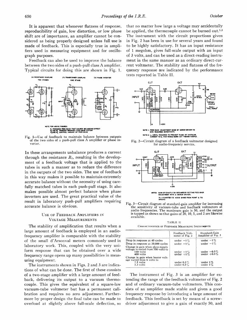
Feedback can also be used to improve the balancebetween the two sides of a push-pull class A amplifier.Typical circuits for doing this are shown in Fig. 1.
(a) RESISTANCE COUPLING
TWO STAGES
R5
R2 0RI 4
hi} TRANSFORMER COUPUINGONE STAGE
XC) PHASE INVERTER
that no matter how large a voltage may accidentallybe applied, the thermcouple cannot be burned out.1 2
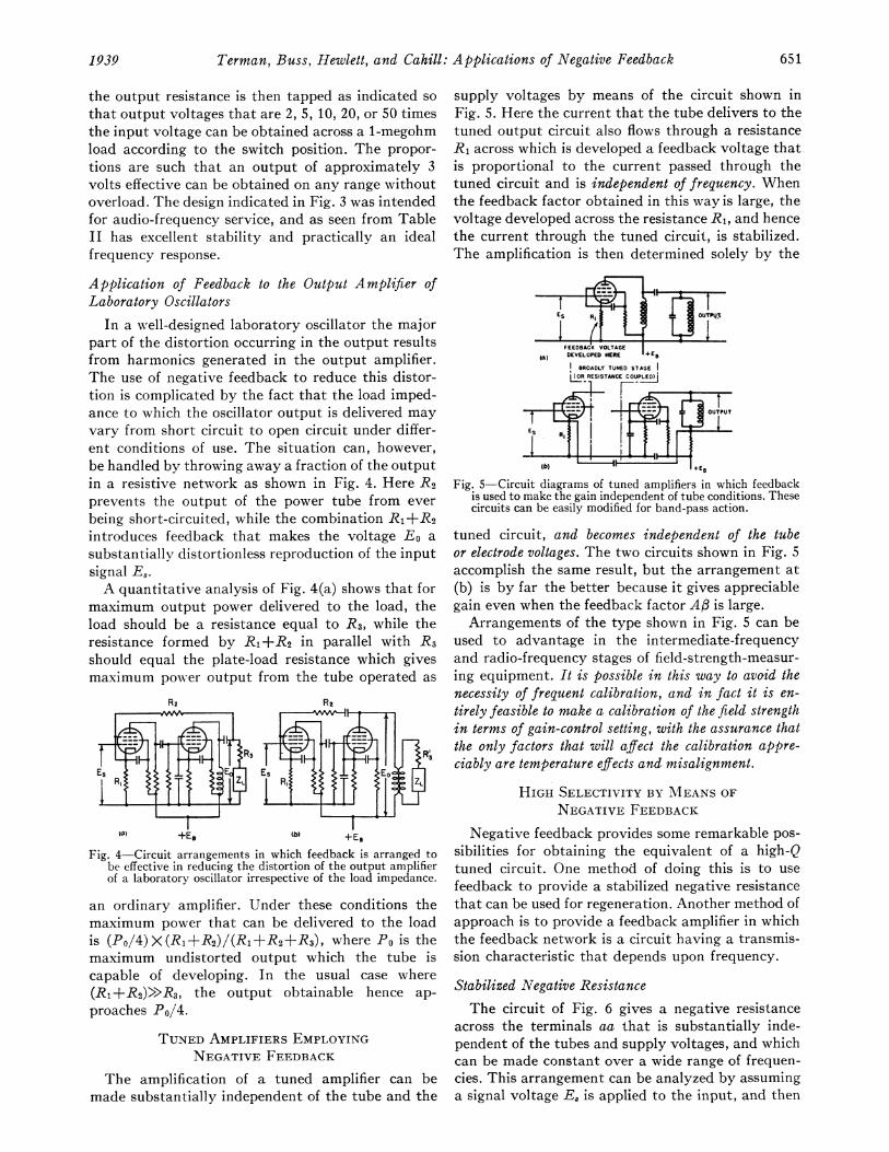
The instrument with the circuit proportions givenin Fig. 2 has been in use for several years and foundto be highly satisfactory. It has an input resistanceof 1 megohm, gives full-scale output with an inputof 3 volts, and can be used as a direct-reading instru-ment in the same manner as an ordinary direct-cur-rent voltmeter. The stability and flatness of the fre-quency response are indicated by the performancetests reported in Table II.
I-HIGH :R2RESIS-TANC
6J7
0.01
INPUT o .
HF
71I
NOTE FOR ASOVE FIGURES:
RI PROOItCES FED-RACK THAT CAUSES BALANCING EFFECTR2 AND Rp PROCUCE ORDINARY FEED-RACK ACTIONR3AND W3 CONTROL AMOUNT OF FEED-BACK
Fig. 1-Use of feedback to maintain balance between outputsof the two sides of a push-pull class A amplifier or phase in-verter.
In these arrangements unbalance produces a currentthrough the resistance R1, resulting in the develop-ment of a feedback voltage that is applied to thetubes in such a manner as to reduce the differencein the outputs of the two sides. The use of feedbackin this way makes it possible to maintain extremelyaccurate balance without the necessity of using care-
fully matched tubes in each push-pull stage. It alsomakes possible almost perfect balance when phaseinverters are used. The great practical value of theresult in laboratory push-pull amplifiers requiringaccurate balance is obvious.
USE OF FEEDBACK AMPLIFIERS IN
VOLTAGE MEASUREMENTS
The stability of amplification that results when a
large amount of feedback is employed in an audio-frequency amplifier is comparable with the stabilityof the small d'Arsonval meters commonly used inlaboratory work. This, coupled with the very uni-form response that can be obtained over a widefrequency range opens up many possibilities in meas-
uring equipment.The instruments shown in Figs. 2 and 3 are indica-
tions of what can be done. The first of these consistsof a two-stage amplifier with a large amount of feed-back, delivering its output to a vacuum thermo-couple. This gives the equivalent of a square-lawvacuum-tube voltmeter but has a permanent cali-bration and requires no zero adjustment. Further-more by proper design the final tube can be made tooverload at slightly above full-scale deflection, so
I 28DM 00W
r
6K7 4.0
0.25 Cg
'- * 1 ---METER
L OOH
Oo
Cyo2 n5A1TM THERMO-
COUPLE
+
4 250
NOTE I: FEED SACK ADJUSTMENT MADE mY SCREW DRIVER TOGIVE REQUIRED SENSITIVITY.
NOTE 2: Li AND RI REQUIRED TO PREVENT RUSH OF CHARGINGCURRENT TO C, THAT WOULD BURN OUT THERMO -COUPLE.
Fig. 2-Circuit diagram of a feedback voltmeter designedfor audio-frequency service.
6J7 6K7 o,1
o H>~~~~~~~~~~~~~~~~~~tINPUT t v s2.0' 2IOINPUT 0 ~~~~- GM5OUTPUT
|ADJtUSTMENT l. l_
4 250
NOTES GAIN OF EXACTLY DO OSTAIEDOSY SETTING FEED-BACKADJUSTMENT WITH A SCREW DRIVER.
R-ADJUSTED T0 4000 OHMS FROM POINT S TOGROUND.
Fig. 3-Circuit diagram of standard-gain amplifier for increasingthe sensitivity of vacuum-tube and feedback voltmeters ataudio frequencies. The maximum gain is 50, and the outputis tapped as shown so that gains of 20, 10, 5, and 2 are likewiseavailable.
TABLE II
CHARACTERISTICS OF FEEDBACK MEASURING INSTRUMENTS
Feedback Volt- Standard-Gainmeter of Fig. 2 Amplifier of Fig. 3
Drop in response at 40 cycles under -1 % under -1 %Drop in response at 20000 cycles under -1 % under -1%Change in gain when plate-supplyvoltage is varied from 250 volts to
140 volts under -1 under -0.5 %400 volts under +±1 under +0.5 %
Change in gain when heater volt-age varied from 6 volts to
7.5 volts under 0.5 W under 1 %5.3 volts under 0.5 % under 1 %
The instrument of Fig. 3 is an amplifier for ex-
tending the range of the feedback voltmeter of Fig. 2and of ordinary vacuum-tube voltmeters. This con-
sists of an amplifier made stable and given a goodfrequency response by introducing a large amount offeedback. This feedback is set by means of a screw-
driver adjustment to give a gain of exactly 50, and
650 October
t . t l
Terman, Buss, Hewlett, and Cahill: Applications of Negative Feedback
the output resistance is then tapped as indicated sothat output voltages that are 2, 5, 10, 20, or 50 timesthe input voltage can be obtained across a 1-megohmload according to the switch position. The propor-tions are such that an output of approximately 3volts effective can be obtained on any range withoutoverload. The design indicated in Fig. 3 was intendedfor audio-frequency service, and as seen from TableII has excellent stability and practically an idealfrequency response.
Application of Feedback to the Output Amplifier ofLaboratory Oscillators
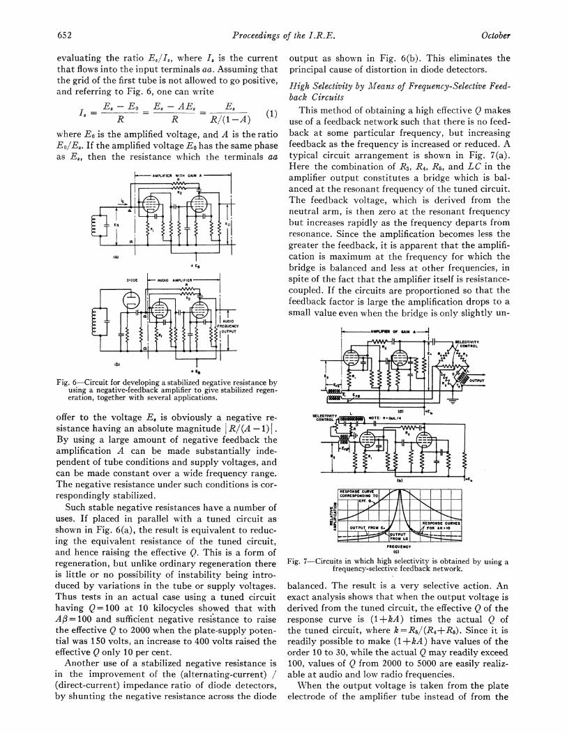
In a well-designed laboratory oscillator the majorpart of the distortion occurring in the output resultsfrom harmonics generated in the output amplifier.The use of negative feedback to reduce this distor-tion is complicated by the fact that the load imped-ance to which the oscillator output is delivered mayvary from short circuit to open circuit under differ-ent conditions of use. The situation can, however,be handled by throwing away a fraction of the outputin a resistive network as shown in Fig. 4. Here R2prevents the output of the power tube from everbeing short-circuited, while the combination R1+R2introduces feedback that makes the voltage Eo asubstantially distortionless reproduction of the inputsignal Es.A quantitative analysis of Fig. 4(a) shows that for
maximum output power delivered to the load, theload should be a resistance equal to R3, while theresistance formed by R1+R2 in parallel with R3should equal the plate-load resistance which givesmaximum power output from the tube operated as
R2
(a) +tE, e(b) +EB
Fig. 4-Circuit arrangements in which feedback is arranged tobe effective in reducing the distortion of the output amplifierof a laboratory oscillator irrespective of the load impedance.
an ordinary amplifier. Under these conditions themaximum power that can be delivered to the loadis (P0/4)X(R1+R2)/(R1+R2+R3), where Po is themaximum undistorted output which the tube iscapable of developing. In the usual case where(R1+R2)>>R3, the output obtainable hence ap-
proaches P0/4.
TUNED AMPLIFIERS EMPLOYINGNEGATIVE FEEDBACK
The amplification of a tuned amplifier can bemade substantially independent of the tube and the
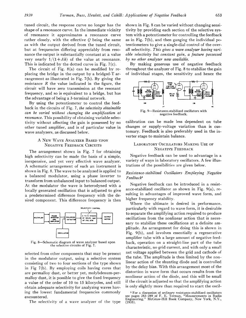
supply voltages by means of the circuit shown inFig. 5. Here the current that the tube delivers to thetuned output circuit also flows through a resistanceR, across which is developed a feedback voltage thatis proportional to the current passed through thetuned circuit and is independent of frequency. Whenthe feedback factor obtained in this way is large, thevoltage developed across the resistance R1, and hencethe current through the tuned circuit, is stabilized.The amplification is then determined solely by the
I ILI?FEEDBACK VOLTAGE
(A) DEVELOPED HERE E9BROADLY TUNED STAGE
LL RESISTANCE COUPLE3
(b) ~~~~~~~~+E8
Fig. 5-Circuit diagrams of tuned amplifiers in which feedbackis used to make the gain independent of tube conditions. Thesecircuits can be easily modified for band-pass action.
tuned circuit, and becomes independent of the tubeor electrode voltages. The two circuits shown in Fig. 5accomplish the same result, but the arrangement at(b) is by far the better because it gives appreciablegain even when the feedback factor AOi is large.
Arrangements of the type shown in Fig. 5 can beused to advantage in the intermediate-frequencyand radio-frequency stages of field-strength-measur-ing equipment. It is possible in this way to avoid thenecessity of frequent calibration, and in fact it is en-tirely feasible to make a calibration of the field strengthin terms of gain-control setting, with the assurance thatthe only factors that will affect the calibration appre-ciably are temperature effects and misalignment.
HIGH SELECTIVITY BY MEANS OFNEGATIVE FEEDBACK
Negative feedback provides some remarkable pos-sibilities for obtaining the equivalent of a high-Qtuned circuit. One method of doing this is to usefeedback to provide a stabilized negative resistancethat can be used for regeneration. Another method ofapproach is to provide a feedback amplifier in whichthe feedback network is a circuit having a transmis-sion characteristic that depends upon frequency.
Stabilized Negative ResistanceThe circuit of Fig. 6 gives a negative resistance
across the terminals aa that is substantially inde-pendent of the tubes and supply voltages, and whichcan be made constant over a wide range of frequen-cies. This arrangement can be analyzed by assuminga signal voltage EB is applied to the input, and then
1939 651
Proceedings of the I.R.E.
evaluating the ratio E,/18, where 18 is the currentthat flows into the input terminals aa. Assuming thatthe grid of the first tube is not allowed to go positive,and referring to Fig. 6, one can write
Es-E o Es-AEs E_(,R R R/(1-A)
where Eo is the amplified voltage, and A is the ratioEolE8. If the amplified voltage Eo has the same phaseas E8, then the resistance which the terminals aa
+ ES
Fig. 6-Circuit for developing a stabilized negative resistance byusing a negative-feedback amplifier to give stabilized regen-eration, together with several applications.
offer to the voltage E8 is obviously a negative re-
sistance having an absolute magnitude R/(A -1) I.By using a large amount of negative feedback theamplification A can be made substantially inde-pendent of tube conditions and supply voltages, andcan be made constant over a wide frequency range.
The negative resistance under such conditions is cor-
respondingly stabilized.Such stable negative resistances have a number of
uses. If placed in parallel with a tuned circuit as
shown in Fig. 6(a), the result is equivalent to reduc-ing the equivalent resistance of the tuned circuit,and hence raising the effective Q. This is a form ofregeneration, but unlike ordinary regeneration thereis little or no possibility of instability being intro-duced by variations in the tube or supply voltages.Thus tests in an actual case using a tuned circuithaving Q= 100 at 10 kilocycles showed that withAO = 100 and sufficient negative resistance to raisethe effective Q to 2000 when the plate-supply poten-tial was 150 volts, an increase to 400 volts raised theeffective Q only 10 per cent.Another use of a stabilized negative resistance is
in the improvement of the (alternating-current) /
(direct-current) impedance ratio of diode detectors,by shunting the negative resistance across the diode
output as shown in Fig. 6(b). This eliminates theprincipal cause of distortion in diode detectors.
High Selectivity by Means of Frequency-Selective Feed-back Circuits
This method of obtaining a high effective Q makesuse of a feedback network such that there is no feed-back at some particular frequency, but increasingfeedback as the frequency is increased or reduced. Atypical circuit arrangement is shown in Fig. 7(a).Here the combination of R3, R4, R5, and LC in theamplifier output constitutes a bridge which is bal-anced at the resonant frequency of the tuned circuit.The feedback voltage, which is derived from theneutral arm, is then zero at the resonant frequencybut increases rapidly as the frequency departs fromresonance. Since the amplification becomes less thegreater the feedback, it is apparent that the amplifi-cation is maximum at the frequency for which thebridge is balanced and less at other frequencies, inspite of the fact that the amplifier itself is resistance-coupled. If the circuits are proportioned so that thefeedback factor is large the amplification drops to a
small value even when the bridge is only slightly un-
RESPONSE CURVECORRESPONDING TO
RESPONSE CURVESOUTPUT FROM E. FOR AK*10
-c OUTP'UT - -=FROM LC
FREQUENCY(C)
Fig. 7-Circuits in which high selectivity is obtained by using afrequency-selective feedback network.
balanced. The result is a very selective action. Anexact analysis shows that when the output voltage isderived from the tuned circuit, the effective Q of theresponse curve is (1 +kA) times the actual Q ofthe tuned circuit, where k=R5/(R4+R5). Since it isreadily possible to make (1 +kA) have values of theorder 10 to 30, while the actual Q may readily exceed100, values of Q from 2000 to 5000 are easily realiz-able at audio and low radio frequencies.When the output voltage is taken from the plate
electrode of the amplifier tube instead of from the
652 October
Terman, Buss, Hewlett, and Cahill: Applications of Negative Feedback
tuned circuit, the response curve no longer has theshape of a resonance curve. In the immediate vicinityof resonance it approximates a resonance curverather closely, with the effective Q being the sameas with the output derived from the tuned circuit,but at frequencies differing appreciably from reso-nance the output is substantially constant at a valuevery nearly 1/(1+Ak) of the value at resonance.This is indicated by the dotted curve in Fig. 7(c).The circuit of Fig. 8(a) can be modified by re-
placing the bridge in the output by a bridged-T ar-rangement as illustrated in Fig. 7(b). By giving theresistance R the value indicated in the figure, thecircuit will have zero transmission at the resonantfrequency, and so is equivalent to a bridge, but hasthe advantage of being a 3-terminal network.By using the potentiometer to control the feed-
back in the circuits of Fig. 7, the selectivity obtainablecan be varied without changing the amplification atresonance. This possibility of obtaining variable selec-tivity without affecting the gain is possessed by noother tuned amplifier, and is of particular value inwave analyzers, as discussed below.
A NEW WAVE ANALYZER BASED UPONNEGATIVE FEEDBACK CIRCUITS
The arrangement shown in Fig. 7 for obtaininghigh selectivity can be made the basis of a simple,inexpensive, and yet very effective wave analyzer.A schematic arrangement of such an instrument isshown in Fig. 8. The wave to be analyzed is applied toa balanced modulator, using a phase inverter totransform from unbalanced input to balanced output.At the modulator the wave is heterodyned with alocally generated oscillation that is adjusted to givea predetermined difference frequency with the de-sired component. This difference frequency is then
SELECTIVITY CONTROL
Fig. 8-Schematic diagram of wave analyzer based uponthe selective circuits of Fig. 7.
selected from other components that may be presentin the modulator output, using a selective systemconsisting of two to four sections of the type shownin Fig 7(b). By employing coils having cores thatare permalloy dust, or better yet, molybdenum-per-malloy dust, it is possible to give the fixed frequencya value of the order of 10 to 15 kilocycles, and stillobtain adequate selectivity for analyzing waves hav-ing the lowest fundamental frequencies commonlyencountered.The selectivity of a wave analyzer of the type
shown in Fig. 8 can be varied without changing sensi-tivity by providing each section of the selective sys-tem with a potentiometer for controlling the feedbackas in Fig. 7(b), and then ganging the individual po-tentiometers to give a single-dial control of the over-all selectivity. This gives a wave analyzer having vari-able selectivity but constant gain, a feature possessedby no other analyzer now available.By making generous use of negative feedback
throughout the analyzer of Fig. 8 to stabilize the gainof individual stages, the sensitivity and hence the
Fig. 9-Resistance-stabilized oscillators withnegative feedback.
calibration can be made less dependent on tubechanges or supply-voltage variation than is cus-tomary. Feedback is also preferably used in the in-verter stage to maintain balance.
LABORATORY OSCILLATORS MAKING USE OFNEGATIVE FEEDBACK
Negative feedback can be used to advantage in avariety of ways in laboratory oscillators. A few illus-trations of the possibilities are given below.
Resistance-stabilized Oscillators Employing NegativeFeedback3
Negative feedback can be introduced in a resist-ance-stabilized oscillator as shown in Fig. 9(a), re-sulting in advantages of improved wave form, andhigher frequency stability.Where the ultimate is desired in performance,
particularly with regard to wave form, it is desirableto separate the amplifying action required to produceoscillations from the nonlinear action that is neces-sary to stabilize these oscillations at a definite am-plitude. An arrangement for doing this is shown inFig. 9(b), and involves essentially a regenerativeamplifier tube with a large amount of negative feed-back, operation on a straight-line part of the tubecharacteristic, no grid current, and with only a smallnet voltage applied between the grid and cathode ofthe tube. The amplitude is then limited by the non-linear action of the shunting diode and is controlledby the delay bias. With this arrangement most of thedistortion in wave form that occurs results from thenonlinear action of the diode, and this will be smallif the circuit is adjusted so that the amplifying actionis only slightly more than required to start the oscil-
3 For a discussion of ordinary resistance-stabilized oscillatorssee pages 283-289 of F. E. Terman, "Measurements in RadioEngineering," McGraw-Hill Book Company, New York, N.Y.,(1935).
1939 653

Proceedings of the I.R.E.
lations. What small distortion is introduced by thediode is readily calculated by taking advantage ofthe fact that since the current through the diodeflows in the form of pulses of very short duration,then the second-harmonic component of these pulseshas substantially the same amplitude as the funda-mental component. If the effective resistance to thefundamental frequency which the diode must shuntacross the tuned circuit in order to stabilize oscilla-tions is a(QcooL), where a is a constant and QCooL isthe parallel impedance of the tuned circuit at theresonant frequency wo/2r, then it can be readilyshown that
second harmonic voltage 2 (2)fundamental voltage 3aQ
In a practical case Q will usually be in the range 50to 200, while with large feedback to stabilize the
LAMP~ ~ ~ ~ ~
+E
tos~ ~ ~ ~ ~ ~
-4 60
^j ^ 2 4 8RELATIVE FREQUENCY
(6)~~~~~~
Fig. 10 Oscillator using resistance-capacitance tuning.
amplifying action, it is entirely practicable to operatewith values of a as high as 100. The resulting distor-rion is then of the order of 0.01 per cent, giving a
remarkably pure wave.
Two- Terminal Oscillators
The circuit of Fig. 6(a) can be made to operate as
an oscillator by making the negative resistance lessthan the parallel resonant impedance of the tunedcircuit. The amplitude of the oscillations in such an
arrangement can be limited by allowing the amplifierto overload, or by using an auxiliary diode in themanner of Fig. 9(b).
Oscillator with Resistance-Capacitance Tuning
The use of negative feedback makes possible a
practical sine-wave oscillator in which the frequencyis determined by a resistance-capacitance network.An example of such a resistance-capacitance tunedoscillator is shown4 in Fig. 10. Here RjCjR2C2 pro-
4This oscillator somewhat resembles that described by H. H.Scott, in the paper "A new type of selective circuit and someapplications," PROC. I.R.E., vol. 26, pp. 226-236; February,(1938), although differing in a number of respects, such as being
vide the regenerative coupling between the inputand output circuits of the amplifier that is necessaryto maintain oscillations. By proportioning this resist-ance-capacitance network so that R1C1 =R2C2 theratio of voltage at b to voltage at a varies with fre-quency in a manner similar to a resonance curve, asindicated in Fig. 10. At the maximum of this curvethe frequency fo is 1/2wr/rR1R2C1C2 and the voltagesat a and b have the same phase. Oscillations hencetend to occur at the frequencyfo.
For such an oscillator to be satisfactory it is neces-sary that the amplifier associated with the resistance-capacitance network have a phase shift that is in-dependent of changes in supply voltage, etc., andfurthermore there must be some means of controllingthe amplitude of oscillations so that they do notexceed the range over which the tubes will operateas class A amplifiers. The constant amplifier phaseshift is necessary in order to insure a stable frequency.This comes about because the phase angle of thetransfer impedance of the resistance-capacitance net-work from a to b varies only slowly with frequency.Hence a small change in amplifier phase shift suchas could be produced by a variation in supply voltagerequires a very large change in oscillation frequencyto produce a compensating phase shift in the resist-ance-capacitance coupling system. A stable phasecharacteristic can be readily obtained in the ampli-fier by employing a large amount of negative feed-back, such as is obtained in Fig. 10 by suitably pro-portioning the resistance combination R3R4.Amplitude control is obtained by a nonlinear ac-
tion in the amplifier circuits that prevents the oscil-lations from building up to such a large amplitudethat distortion occurs. It is possible to employ anyone of a variety of systems, but the one shown in Fig.10 is recommended as being both simple and effec-tive. Here the resistance R]3 is supplied by a smallincandescent lamp, and the operating conditions soadjusted that the current through this lamp is suchthat the filament operates at a temperature wherethe resistance varies rapidly with current. As aresult, an increase in oscillation amplitude increasesthe lamp resistance. This makes the negative feed-back larger, so decreases the gain of the amplifier andreduces the tendency to oscillate. Similarly, as theoscillations decrease in amplitude the currentthrough the lamp is reduced, lowering the lamp re-sistance, reducing the negative feedback, and therebyincreasing the tendency to oscillate. The result isthat a constant amplitude is maintained, with notendency to distort the wave shape.
In practical oscillators of this type it is most con-
provided with amplitude control and having the frequencyadjusted by variable condensers rather than variable resistors.The latter feature makes the impedance from a to ground con-stant as the capacitance is varied to change the frequency, andso greatly simplifies the design of the amplifier circuits.
654
venient to make R1=R2, and Ci = C2. Under theseconditions the frequency of oscillation is
frequency= 2 (3)27R1C1R(3It will be noted that this frequency is inversely pro-portional to capacitance, instead of inversely propor-tional to the square root of capacitance as is the casein ordinary tuned circuits. Accordingly if the fre-quency is varied by means of an ordinary gang-tuning condenser such as used in broadcast receivers,a frequency range of 10 to 1 can be covered on asingle dial. Decimal multiplying factors for frequen-cies can be obtained by changing resistances R1 andR2 in decimal values.The arrangement of Fig. 10 provides an inexpen-
sive and yet highly satisfactory laboratory oscillatorcapable of performing most of the functions of abeat-frequency oscillator. One version that has beenconstructed employs a four-gang broadcast con-denser with sections paralleled in pairs for tuning andcovers the frequency range 20 to 20,000 cycles inthree subdivisions (20 to 200, 200 to 2000, and 2000to 20,000 cycles) by employing three sets of resist-ances. The output voltage is constant within approxi-mately 10 per cent over the entire frequency range,and has only about 0.25 per cent distortion. A fewchecks on frequency stability indicate negligible fre-
quency shift (less than 0.1 per cent) with large varia-tions in supply voltage.
Experimental oscillators of this type have beenbuilt that operate at frequencies exceeding 2 mega-cycles.
CONCLUSIONThe various applications of negative feedback that
have been described in this paper by no means ex-haust the possibilities that this new technique opensup, but rather merely suggest the important partthat feedback is bound to play in the measuring andlaboratory equipment of the future. Merely scratch-ing the surface as has been done in this paper does,however, bring to view such interesting devices asimproved forms of vacuum-tube voltmeters with un-limited sensitivity and a permanent calibration, de-tectors with the main cause of distortion removed,circuits with amazingly high Q, field-strength-meas-uring sets with a sensitivity that does not vary withtube conditions or supply voltages, new types ofwave analyzers, new types of oscillators, etc.
ACKNOWLEDGMENTThe authors wish to express their appreciation for
suggestions and helpful discussions contributed byEdward L. Ginzton of the Stanford CommunicationLaboratory group.
Critical Inductance and Control Rectifiers*W. P. OVERBECK t, ASSOCIATE MEMBER, I.R.E.
Summary-This paper explains the effect of a choke-inputfilter when used in connection with controllable rectifier tubes. Manyof the difficulties experienced with instability and discontinuitiesof control of such rectifiers are due to an improper choice of input-choke inductance. A mathematical derivation of the proper valueof inductance is given and a simple method of applying it to actualproblems is illustrated.
INTRODUCTION
CMOOTHING filters for rectifiers fall into twoS main classes, condenser input and choke input.
For industrial applications, the choke-inputfilter is considered superior because it lowers peak-current requirements for the rectifier tubes, it im-proves the form factor of the current pulses throughthe rectifier tubes and plate transformer, it providesbetter regulation to load at the output of the recti-fier, and it aids in balancing the currents through thetubes.
In order that the input choke may perform thesefunctions adequately, a value of inductance is chosenwhich is greater than a so-called "critical" value.For ordinary rectifiers, this value has been obtained
* Decimal classification: R386. Original manuscript receivedby the Institute, November 22, 1938.
t Raytheon Production Corporation, Newton, Mass.
by empirical methods which have proved satis-factory.' For rectifiers employing controllable tubessuch as Permatrons,2 Thyratrons,3 or Ignitrons,4 ithas been found that the duties of the input chokeare much more complex and that it plays a large partin the problem of obtaining proper control of therectifier tubes. The writer has developed an accuratemethod of determining the proper size of the inputchoke to meet any given output voltage or load re-quirements of a controlled rectifier.
DEFINITION OF "CRITICAL INDUCTANCE"Consider a rectifier circuit such as that of Fig. 1.
With the filter choke removed, current will flowthrough the tubes in short pulses during the anode-voltage peaks. As inductance is added, these pulses
I F. E. Terman, "Radio Engineering," page 410, McGraw-Hill Book Company, New York, N. Y., (1932).
2 W. P. Overbeck, "The Permatron-a magnetically controlledindustrial tube," Trans. A.I.E.E., vol. 58, pp. 224-228; May,(1939).
3 A. W. Hull, "Hot cathode Thyratrons," Gen. Elec. Rev.,vol. 32, pp. 213-223; April, (1929); and vol. 32, pp. 390-399;July, (1929).
4 D. D. Knowles, "The Ignitron, a new controlled rectifier,"Electronics, vol. 6, pp. 164-166; June, (1933).
Proceedings of the I.R.E. 655October, 1939