wp3x00 mk ll controller control tem - mita-teknik
TRANSCRIPT

control systemsWP3x00 MK ll Controller
MT_WP3x00 MK ll_DataSheet_R3_0
®
© 2015 Mita-Teknik. All rights reserved
The WP3x00 MK ll ControllerThe WP3x00 MK II controller is specifically designed to replace existing WP3x00 controllers in the market, and to give our customers the benefits of state-of-art communication interfaces and protocols. The WP3x00 MK ll controller ensures optimal operation, active security and advanced data collection. The on-board grid interface makes it possible to calculate main grid parameters by precise and reliable DSP algorithms, according to IEC 61400-21 standard. The controller is equipped with two high-speed gigabit ethernet interfaces working as separate network interfaces. The controller also features safety chain relay logic.
The controller is equipped with internal maintenance-free power back-up, ensuring that all data is stored in the event of system power failure (UPS shutdown/failure) and program update.
The controller uses the advanced OS1xx Operating System software, featuring the Failsafe Flash file system, TCP/IP protocol stack, WEB-server, plug-and-play identification/configuration of all WP-Line modules, status code system, 30-year summation structure, menu system and log systems.
The controller handles the executing of up to 10 different synchronous/asynchronous applications running in parallel. As an example this can be: turbine control application, standard communication protocols, customer specific communication protocols, CoDeSys RTS, etc. The controller supports the IEC 61131-3 (CoDeSys) PLC programming languages, as well as advanced programming in C and C++, using PEPTOOL or other programming tool of your choice.
› All control functions are integrated › Integrated realtime grid measurement
› Gigabit Ethernet, Serial RS232/RS422/RS485
› Direct integration with safety system
› Advanced data collection and storage
› Mechanically compatible with WP3x00
› Maintenance free - no fans and no batteries that need replacement
control systemsWP3x00 MK ll Controller
MT_WP3x00 MK ll_DataSheet_R3_0
®
© 2015 Mita-Teknik. All rights reserved
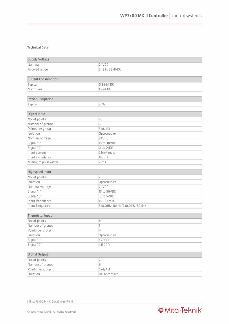
Technical Data
Nominal 24VDCAllowed range 21.6 to 26.4VDC
Typical 0.856A DCMaximum 1.22A DC
Typical 25W
No. of points 43Number of groups 6Points per group 5x8/1x3Isolation OptocouplerNominal voltage 24VDCSignal "1" 15 to 30VDCSignal "0" 0 to 5VDCInput current 25mA max.Input impedance 1500ΩMinimum pulsewidth 21ms
No. of points 7Isolation OptocouplerNominal voltage 24VDCSignal "1" 15 to 30VDCSignal "0" 0 to 5VDCInput impedance 1500Ω min.Input frequency 5x0.01Hz-10kHz/2x0.01Hz-80kHz
No. of points 4Number of groups 1Points per group 4Isolation OptocouplerSignal "1" >2800ΩSignal "0" <1300Ω
No. of points 24Number of groups 9Points per group 5x4/4x1Isolation Relay contact
Digital Output
Power Dissipation
Supply Voltage
Current Consumption
Digital Input
Highspeed Input
Thermistor Input
control systemsWP3x00 MK ll Controller
MT_WP3x00 MK ll_DataSheet_R3_0
®
© 2015 Mita-Teknik. All rights reserved
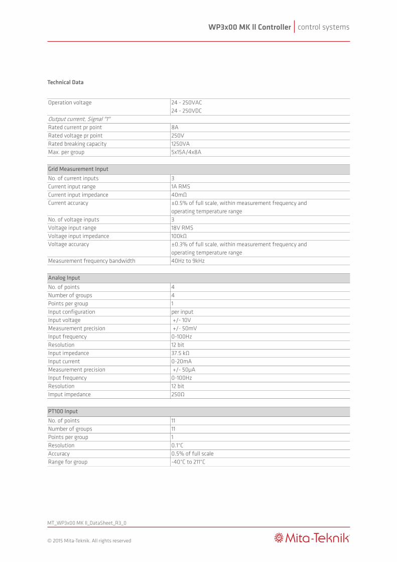
Technical Data
Operation voltage 24 - 250VAC24 - 250VDC
Output current, Signal "1"Rated current pr point 8ARated voltage pr point 250VRated breaking capacity 1250VAMax. per group 5x15A/4x8A
No. of current inputs 3Current input range 1A RMSCurrent input impedance 40mΩCurrent accuracy ±0.5% of full scale, within measurement frequency and
operating temperature range No. of voltage inputs 3Voltage input range 18V RMSVoltage input impedance 100kΩVoltage accuracy ±0.3% of full scale, within measurement frequency and
operating temperature rangeMeasurement frequency bandwidth 40Hz to 9kHz
No. of points 4Number of groups 4Points per group 1Input configuration per inputInput voltage +/- 10VMeasurement precision +/- 50mVInput frequency 0-100HzResolution 12 bitInput impedance 37.5 kΩInput current 0-20mAMeasurement precision +/- 50µAInput frequency 0-100HzResolution 12 bitImput impedance 250Ω
No. of points 11Number of groups 11Points per group 1Resolution 0.1°CAccuracy 0.5% of full scaleRange for group -40°C to 211°C
Grid Measurement Input
Analog Input
PT100 Input
control systemsWP3x00 MK ll Controller
MT_WP3x00 MK ll_DataSheet_R3_0
®
© 2015 Mita-Teknik. All rights reserved
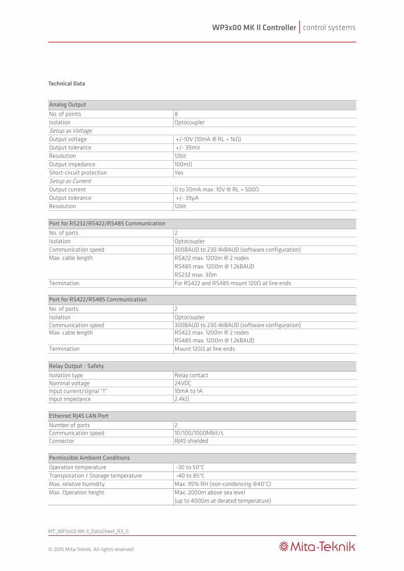
Technical Data
No. of points 8Isolation OptocouplerSetup as VoltageOutput voltage +/-10V (10mA @ RL = 1kΩ)Output tolerance +/- 39mVResolution 12bitOutput impedance 100mΩShort-circuit protection YesSetup as CurrentOutput current 0 to 20mA max. 10V @ RL = 500ΩOutput tolerance +/- 39µAResolution 12bit
No. of ports 2Isolation OptocouplerCommunication speed 300BAUD to 230.4kBAUD (software configuration)
RS422 max. 1200m @ 2 nodes RS485 max. 1200m @ 1.2kBAUDRS232 max. 30m
Termination For RS422 and RS485 mount 120Ω at line ends
No. of ports 2Isolation OptocouplerCommunication speed 300BAUD to 230.4kBAUD (software configuration)Max. cable length RS422 max. 1200m @ 2 nodes
RS485 max. 1200m @ 1.2kBAUDTermination Mount 120Ω at line ends
Isolation type Relay contactNominal voltage 24VDCInput current/signal “1” 10mA to 1AInput impedance 2.4kΩ
Number of ports 2Communication speed 10/100/1000Mbit/sConnector RJ45 shielded
Operation temperature -30 to 50°CTranspotation / Storage temperature -40 to 85°CMax. relative humidity Max. 95% RH (non-condensing @40°C)Max. Operation height Max. 2000m above sea level
(up to 4000m at derated temperature)
Analog Output
Port for RS232/RS422/RS485 Communication
Permissible Ambient Conditions
Ethernet RJ45 LAN Port
Relay Output - Safety
Port for RS422/RS485 Communication
Max. cable length
control systemsWP3x00 MK ll Controller
MT_WP3x00 MK ll_DataSheet_R3_0
®
© 2015 Mita-Teknik. All rights reserved
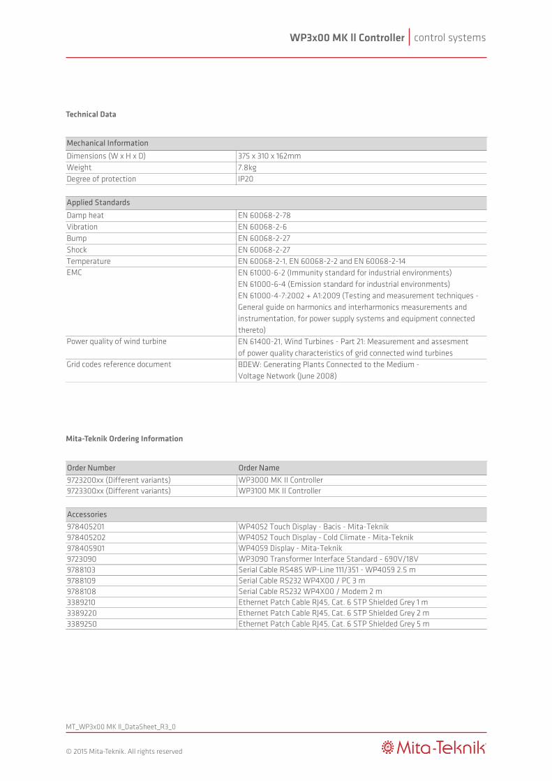
Technical Data
Mita-Teknik Ordering Information
Order Number Order Name9723200xx (Different variants) WP3000 MK II Controller 9723300xx (Different variants) WP3100 MK II Controller
Accessories978405201 WP4052 Touch Display - Bacis - Mita-Teknik978405202 WP4052 Touch Display - Cold Climate - Mita-Teknik978405901 WP4059 Display - Mita-Teknik9723090 WP3090 Transformer Interface Standard - 690V/18V9788103 Serial Cable RS485 WP-Line 111/351 - WP4059 2.5 m9788109 Serial Cable RS232 WP4X00 / PC 3 m9788108 Serial Cable RS232 WP4X00 / Modem 2 m3389210 Ethernet Patch Cable RJ45, Cat. 6 STP Shielded Grey 1 m3389220 Ethernet Patch Cable RJ45, Cat. 6 STP Shielded Grey 2 m3389250 Ethernet Patch Cable RJ45, Cat. 6 STP Shielded Grey 5 m
Dimensions (W x H x D) 375 x 310 x 162mmWeight 7.8kgDegree of protection IP20
Damp heat EN 60068-2-78Vibration EN 60068-2-6Bump EN 60068-2-27Shock EN 60068-2-27Temperature EN 60068-2-1, EN 60068-2-2 and EN 60068-2-14EMC EN 61000-6-2 (Immunity standard for industrial environments)
EN 61000-6-4 (Emission standard for industrial environments)EN 61000-4-7:2002 + A1:2009 (Testing and measurement techniques - General guide on harmonics and interharmonics measurements and instrumentation, for power supply systems and equipment connected thereto)
Power quality of wind turbine EN 61400-21, Wind Turbines - Part 21: Measurement and assesment of power quality characteristics of grid connected wind turbines
Grid codes reference document BDEW: Generating Plants Connected to the Medium - Voltage Network (June 2008)
Applied Standards
Mechanical Information

control systemsWP3400 MK II Controller
MT_WP3400 MK ll_DataSheet_R1_0
®
© 2018 Mita-Teknik. All rights reserved
Specifications subject to change
The WP3400 MK II ControllerThe WP3400 MK II Controller is specifically designed to replace existing NEG Micon Control Systems for NM52 turbines in the market and to give our customers the benefits of state-of–art communication interfaces and protocols. The WP3400 MK II Controller ensures optimal operation, active security and advanced data collection. The on-board grid interface makes it possible to calculate main grid parameters by precise and reliable DSP algorithms according to IEC 61400-21 standard. The controller is equipped with high-speed Ethernet interfaces that work as separate network interfaces. The controller also features safety chain relay logic.
The controller is equipped with internal maintenance-free power back-up, ensuring all data is stored in the event of system power failure (UPS shutdown/failure) and program update.
The controller uses the advanced OS1xx Operating System software, featuring the Failsafe Flash file system, TCP/IP protocol stack, WEB-server, plug-and-play identification/configuration of all WP-Line modules, status code system, 30-year summation structure, menu system and log systems.
The controller handles the executing of up to 10 different synchronous/asynchronous applications running in parallel. As an example, this can be turbine control application, standard communication protocols, customer specific communication protocols, CoDeSys RTS, etc. The controller supports the IEC 61131-3 (CoDeSys) PLC programming languages as well as advanced programming in C and C++, using PEPTOOL or other programming tool of your choice.
The WP3400 MK II Control System consist of two boxes, one installed in the nacelle and at the tower base.
› Mechanically compatible with NEG Micon Control Systems for NM52 › Maintenance free - no fans and no batteries that need replacement
› All control functions are integrated
› Integrated realtime grid measurement
› Ethernet and serial RS485
› Direct integration with safety system
› Advanced data collection and storage
control systemsWP3400 MK II Controller
MT_WP3400 MK ll_DataSheet_R1_0
®
© 2018 Mita-Teknik. All rights reserved
Specifications subject to change
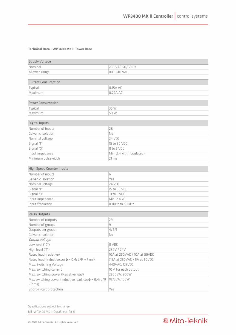
Technical Data - WP3400 MK II Tower Base
Nominal 230 VAC 50/60 HzAllowed range 100-240 VAC
Typical 0.15A ACMaximum 0.22A AC
Typical 35 WMaximum 50 W
Number of inputs 28Galvanic Isolation NoNominal voltage 24 VDCSignal "1" 15 to 30 VDCSignal "0" 0 to 5 VDCInput impedance Min. 2.4 kΩ (modulated)Minimum pulsewidth 21 ms
Number of inputs 6Galvanic Isolation YesNominal voltage 24 VDCSignal "1" 15 to 30 VDCSignal "0" 0 to 5 VDCInput impedance Min. 2.4 kΩInput frequency 0.01Hz to 80 kHz
Number of outputs 29Number of groups 9Outputs per group 4/3/1Galvanic Isolation NoOutput voltageLow level ("0") 0 VDCHigh level ("1") 230V / 24VRated load (resistive) 10A at 250VAC / 10A at 30VDCRated load (Inductive,cosφ = 0.4; L/R = 7 ms) 7,5A at 250VAC / 5A at 30VDCMax. Switching Voltage 440VAC, 125VDCMax. switching current 10 A for each outputMax. switching power (Resistive load) 2500VA, 300WMax switching power (Inductive load, cosφ = 0.4; L/R = 7 ms)
1875VA, 150W
Short-circuit protection Yes
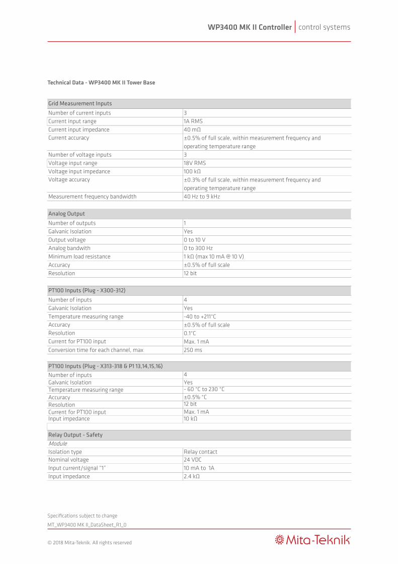
Number of current inputs 3Current input range 1A RMSCurrent input impedance 40 mΩCurrent accuracy ±0.5% of full scale, within measurement frequency and
operating temperature range Number of voltage inputs 3Voltage input range 18V RMSVoltage input impedance 100 kΩVoltage accuracy ±0.3% of full scale, within measurement frequency and
operating temperature rangeMeasurement frequency bandwidth 40 Hz to 9 kHz
Number of outputs 1Galvanic Isolation YesOutput voltage 0 to 10 VAnalog bandwith 0 to 300 HzMinimum load resistance 1 kΩ (max 10 mA @ 10 V)Accuracy ±0.5% of full scaleResolution 12 bit
Number of inputs 4Galvanic Isolation YesTemperature measuring range -40 to +211°CAccuracy ±0.5% of full scaleResolution 0.1°CCurrent for PT100 input Max. 1 mAConversion time for each channel, max 250 ms
Number of inputs 4Galvanic Isolation YesTemperature measuring range - 60 °C to 230 °CAccuracy ±0.5% °CResolution 12 bitCurrent for PT100 input Max. 1 mAInput impedance 10 kΩ
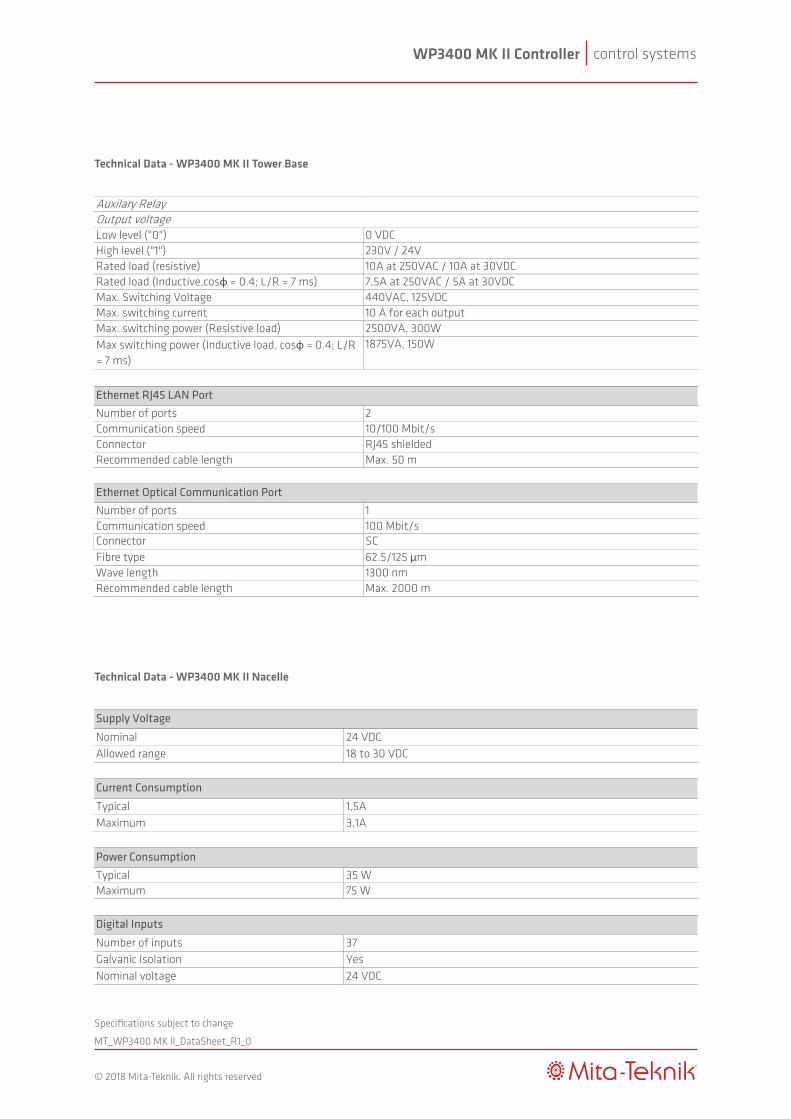
ModuleIsolation type Relay contactNominal voltage 24 VDCInput current/signal “1” 10 mA to 1AInput impedance 2.4 kΩAuxilary RelayOutput voltageLow level ("0") 0 VDCHigh level ("1") 230V / 24VRated load (resistive) 10A at 250VAC / 10A at 30VDCRated load (Inductive,cosφ = 0.4; L/R = 7 ms) 7,5A at 250VAC / 5A at 30VDCMax. Switching Voltage 440VAC, 125VDCMax. switching current 10 A for each outputMax. switching power (Resistive load) 2500VA, 300WMax switching power (Inductive load, cosφ = 0.4; L/R = 7 ms)
1875VA, 150W
Number of ports 2Communication speed 10/100 Mbit/sConnector RJ45 shieldedRecommended cable length Max. 50 m
Number of ports 1Communication speed 100 Mbit/sConnector SCFibre type 62.5/125 μmWave length 1300 nmRecommended cable length Max. 2000 m
Ethernet RJ45 LAN Port
Relay Output - Safety
PT100 Inputs (Plug - X300-312)
PT100 Inputs (Plug - X313-318 & P1 13,14,15,16)
Supply Voltage
Current Consumption
Analog Output
Ethernet Optical Communication Port
Grid Measurement Inputs
High Speed Counter Inputs
Relay Outputs
Digital Inputs
Power Consumption
control systemsWP3400 MK II Controller
MT_WP3400 MK ll_DataSheet_R1_0
®
© 2018 Mita-Teknik. All rights reserved
Specifications subject to change
Technical Data - WP3400 MK II Tower Base
Nominal 230 VAC 50/60 HzAllowed range 100-240 VAC
Typical 0.15A ACMaximum 0.22A AC
Typical 35 WMaximum 50 W
Number of inputs 28Galvanic Isolation NoNominal voltage 24 VDCSignal "1" 15 to 30 VDCSignal "0" 0 to 5 VDCInput impedance Min. 2.4 kΩ (modulated)Minimum pulsewidth 21 ms
Number of inputs 6Galvanic Isolation YesNominal voltage 24 VDCSignal "1" 15 to 30 VDCSignal "0" 0 to 5 VDCInput impedance Min. 2.4 kΩInput frequency 0.01Hz to 80 kHz
Number of outputs 29Number of groups 9Outputs per group 4/3/1Galvanic Isolation NoOutput voltageLow level ("0") 0 VDCHigh level ("1") 230V / 24VRated load (resistive) 10A at 250VAC / 10A at 30VDCRated load (Inductive,cosφ = 0.4; L/R = 7 ms) 7,5A at 250VAC / 5A at 30VDCMax. Switching Voltage 440VAC, 125VDCMax. switching current 10 A for each outputMax. switching power (Resistive load) 2500VA, 300WMax switching power (Inductive load, cosφ = 0.4; L/R = 7 ms)
1875VA, 150W
Short-circuit protection Yes
Number of current inputs 3Current input range 1A RMSCurrent input impedance 40 mΩCurrent accuracy ±0.5% of full scale, within measurement frequency and
operating temperature range Number of voltage inputs 3Voltage input range 18V RMSVoltage input impedance 100 kΩVoltage accuracy ±0.3% of full scale, within measurement frequency and
operating temperature rangeMeasurement frequency bandwidth 40 Hz to 9 kHz
Number of outputs 1Galvanic Isolation YesOutput voltage 0 to 10 VAnalog bandwith 0 to 300 HzMinimum load resistance 1 kΩ (max 10 mA @ 10 V)Accuracy ±0.5% of full scaleResolution 12 bit
Number of inputs 4Galvanic Isolation YesTemperature measuring range -40 to +211°CAccuracy ±0.5% of full scaleResolution 0.1°CCurrent for PT100 input Max. 1 mAConversion time for each channel, max 250 ms
Number of inputs 4Galvanic Isolation YesTemperature measuring range - 60 °C to 230 °CAccuracy ±0.5% °CResolution 12 bitCurrent for PT100 input Max. 1 mAInput impedance 10 kΩ
ModuleIsolation type Relay contactNominal voltage 24 VDCInput current/signal “1” 10 mA to 1AInput impedance 2.4 kΩAuxilary RelayOutput voltageLow level ("0") 0 VDCHigh level ("1") 230V / 24VRated load (resistive) 10A at 250VAC / 10A at 30VDCRated load (Inductive,cosφ = 0.4; L/R = 7 ms) 7,5A at 250VAC / 5A at 30VDCMax. Switching Voltage 440VAC, 125VDCMax. switching current 10 A for each outputMax. switching power (Resistive load) 2500VA, 300WMax switching power (Inductive load, cosφ = 0.4; L/R = 7 ms)
1875VA, 150W
Number of ports 2Communication speed 10/100 Mbit/sConnector RJ45 shieldedRecommended cable length Max. 50 m
Number of ports 1Communication speed 100 Mbit/sConnector SCFibre type 62.5/125 μmWave length 1300 nmRecommended cable length Max. 2000 m
Ethernet RJ45 LAN Port
Relay Output - Safety
PT100 Inputs (Plug - X300-312)
PT100 Inputs (Plug - X313-318 & P1 13,14,15,16)
Supply Voltage
Current Consumption
Analog Output
Ethernet Optical Communication Port
Grid Measurement Inputs
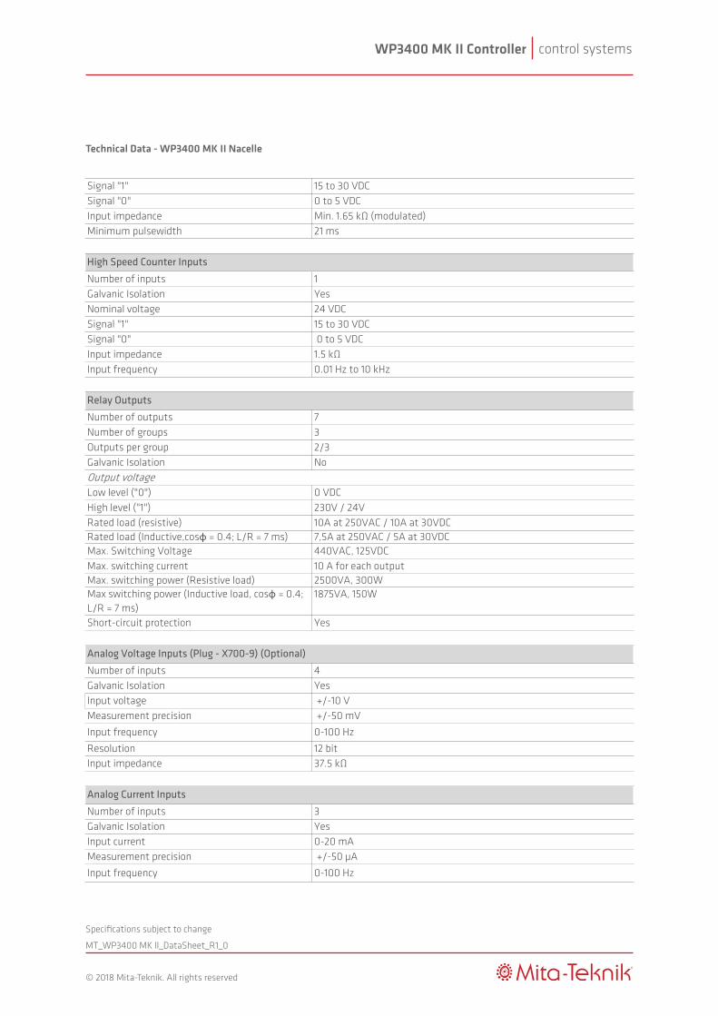
High Speed Counter Inputs
Relay Outputs
Digital Inputs
Power Consumption
control systemsWP3400 MK II Controller
MT_WP3400 MK ll_DataSheet_R1_0
®
© 2018 Mita-Teknik. All rights reserved
Specifications subject to change
Technical Data - WP3400 MK II Tower Base
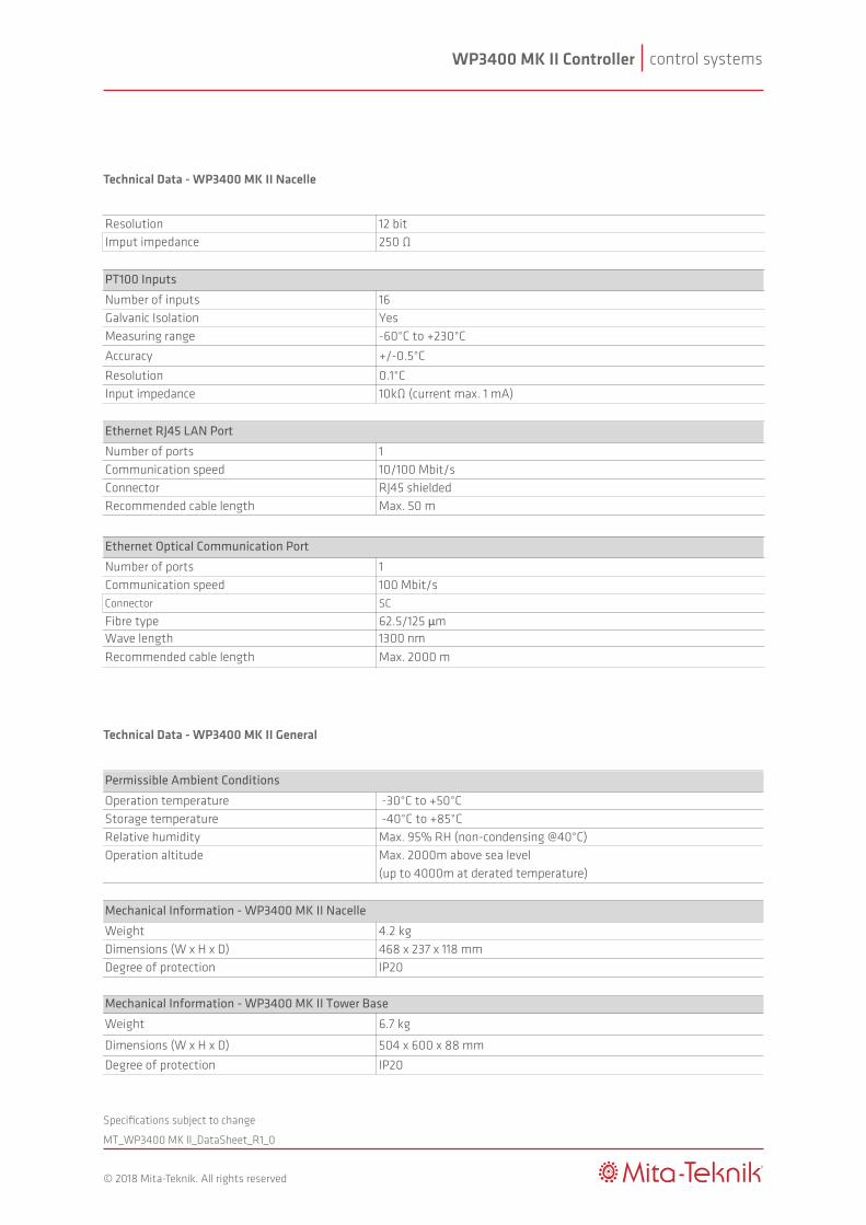
Technical Data - WP3400 MK II Nacelle
Nominal 24 VDC Allowed range 18 to 30 VDC
Typical 1,5A Maximum 3,1A
Typical 35 WMaximum 75 W
Number of inputs 37Galvanic Isolation YesNominal voltage 24 VDCSignal "1" 15 to 30 VDCSignal "0" 0 to 5 VDCInput impedance Min. 1.65 kΩ (modulated)Minimum pulsewidth 21 ms
Number of inputs 1Galvanic Isolation YesNominal voltage 24 VDCSignal "1" 15 to 30 VDCSignal "0" 0 to 5 VDCInput impedance 1.5 kΩInput frequency 0.01 Hz to 10 kHz
Number of outputs 7Number of groups 3Outputs per group 2/3Galvanic Isolation NoOutput voltageLow level ("0") 0 VDCHigh level ("1") 230V / 24VRated load (resistive) 10A at 250VAC / 10A at 30VDCRated load (Inductive,cosφ = 0.4; L/R = 7 ms) 7,5A at 250VAC / 5A at 30VDCMax. Switching Voltage 440VAC, 125VDCMax. switching current 10 A for each outputMax. switching power (Resistive load) 2500VA, 300WMax switching power (Inductive load, cosφ = 0.4; L/R = 7 ms)
1875VA, 150W
Short-circuit protection Yes
Number of inputs 4Galvanic Isolation YesInput voltage +/-10 VMeasurement precision +/-50 mV
Input frequency 0-100 Hz
Resolution 12 bitInput impedance 37.5 kΩ
Number of inputs 3Galvanic Isolation YesInput current 0-20 mAMeasurement precision +/-50 µA
Input frequency 0-100 Hz
Resolution 12 bitImput impedance 250 Ω
Number of inputs 16Galvanic Isolation YesMeasuring range -60°C to +230°C
Accuracy +/-0.5°C
Resolution 0.1°CInput impedance 10kΩ (current max. 1 mA)
Number of ports 1Communication speed 10/100 Mbit/sConnector RJ45 shieldedRecommended cable length Max. 50 m
Number of ports 1Communication speed 100 Mbit/sConnector SC
Fibre type 62.5/125 μmWave length 1300 nmRecommended cable length Max. 2000 m
Supply Voltage
Current Consumption
Analog Voltage Inputs (Plug - X700-9) (Optional)
High Speed Counter Inputs
Relay Outputs
Analog Current Inputs
Digital Inputs
Power Consumption
Ethernet RJ45 LAN Port
Ethernet Optical Communication Port
PT100 Inputs
Nominal 230 VAC 50/60 HzAllowed range 100-240 VAC
Typical 0.15A ACMaximum 0.22A AC
Typical 35 WMaximum 50 W
Number of inputs 28Galvanic Isolation NoNominal voltage 24 VDCSignal "1" 15 to 30 VDCSignal "0" 0 to 5 VDCInput impedance Min. 2.4 kΩ (modulated)Minimum pulsewidth 21 ms
Number of inputs 6Galvanic Isolation YesNominal voltage 24 VDCSignal "1" 15 to 30 VDCSignal "0" 0 to 5 VDCInput impedance Min. 2.4 kΩInput frequency 0.01Hz to 80 kHz
Number of outputs 29Number of groups 9Outputs per group 4/3/1Galvanic Isolation NoOutput voltageLow level ("0") 0 VDCHigh level ("1") 230V / 24VRated load (resistive) 10A at 250VAC / 10A at 30VDCRated load (Inductive,cosφ = 0.4; L/R = 7 ms) 7,5A at 250VAC / 5A at 30VDCMax. Switching Voltage 440VAC, 125VDCMax. switching current 10 A for each outputMax. switching power (Resistive load) 2500VA, 300WMax switching power (Inductive load, cosφ = 0.4; L/R = 7 ms)
1875VA, 150W
Short-circuit protection Yes
Number of current inputs 3Current input range 1A RMSCurrent input impedance 40 mΩCurrent accuracy ±0.5% of full scale, within measurement frequency and
operating temperature range Number of voltage inputs 3Voltage input range 18V RMSVoltage input impedance 100 kΩVoltage accuracy ±0.3% of full scale, within measurement frequency and
operating temperature rangeMeasurement frequency bandwidth 40 Hz to 9 kHz
Number of outputs 1Galvanic Isolation YesOutput voltage 0 to 10 VAnalog bandwith 0 to 300 HzMinimum load resistance 1 kΩ (max 10 mA @ 10 V)Accuracy ±0.5% of full scaleResolution 12 bit
Number of inputs 4Galvanic Isolation YesTemperature measuring range -40 to +211°CAccuracy ±0.5% of full scaleResolution 0.1°CCurrent for PT100 input Max. 1 mAConversion time for each channel, max 250 ms
Number of inputs 4Galvanic Isolation YesTemperature measuring range - 60 °C to 230 °CAccuracy ±0.5% °CResolution 12 bitCurrent for PT100 input Max. 1 mAInput impedance 10 kΩ
ModuleIsolation type Relay contactNominal voltage 24 VDCInput current/signal “1” 10 mA to 1AInput impedance 2.4 kΩAuxilary RelayOutput voltageLow level ("0") 0 VDCHigh level ("1") 230V / 24VRated load (resistive) 10A at 250VAC / 10A at 30VDCRated load (Inductive,cosφ = 0.4; L/R = 7 ms) 7,5A at 250VAC / 5A at 30VDCMax. Switching Voltage 440VAC, 125VDCMax. switching current 10 A for each outputMax. switching power (Resistive load) 2500VA, 300WMax switching power (Inductive load, cosφ = 0.4; L/R = 7 ms)
1875VA, 150W
Number of ports 2Communication speed 10/100 Mbit/sConnector RJ45 shieldedRecommended cable length Max. 50 m
Number of ports 1Communication speed 100 Mbit/sConnector SCFibre type 62.5/125 μmWave length 1300 nmRecommended cable length Max. 2000 m
Ethernet RJ45 LAN Port
Relay Output - Safety
PT100 Inputs (Plug - X300-312)
PT100 Inputs (Plug - X313-318 & P1 13,14,15,16)
Supply Voltage
Current Consumption
Analog Output
Ethernet Optical Communication Port
Grid Measurement Inputs
High Speed Counter Inputs
Relay Outputs
Digital Inputs
Power Consumption
control systemsWP3400 MK II Controller
MT_WP3400 MK ll_DataSheet_R1_0
®
© 2018 Mita-Teknik. All rights reserved
Specifications subject to change
Technical Data - WP3400 MK II Nacelle
Nominal 24 VDC Allowed range 18 to 30 VDC
Typical 1,5A Maximum 3,1A
Typical 35 WMaximum 75 W
Number of inputs 37Galvanic Isolation YesNominal voltage 24 VDCSignal "1" 15 to 30 VDCSignal "0" 0 to 5 VDCInput impedance Min. 1.65 kΩ (modulated)Minimum pulsewidth 21 ms
Number of inputs 1Galvanic Isolation YesNominal voltage 24 VDCSignal "1" 15 to 30 VDCSignal "0" 0 to 5 VDCInput impedance 1.5 kΩInput frequency 0.01 Hz to 10 kHz
Number of outputs 7Number of groups 3Outputs per group 2/3Galvanic Isolation NoOutput voltageLow level ("0") 0 VDCHigh level ("1") 230V / 24VRated load (resistive) 10A at 250VAC / 10A at 30VDCRated load (Inductive,cosφ = 0.4; L/R = 7 ms) 7,5A at 250VAC / 5A at 30VDCMax. Switching Voltage 440VAC, 125VDCMax. switching current 10 A for each outputMax. switching power (Resistive load) 2500VA, 300WMax switching power (Inductive load, cosφ = 0.4; L/R = 7 ms)
1875VA, 150W
Short-circuit protection Yes
Number of inputs 4Galvanic Isolation YesInput voltage +/-10 VMeasurement precision +/-50 mV
Input frequency 0-100 Hz
Resolution 12 bitInput impedance 37.5 kΩ
Number of inputs 3Galvanic Isolation YesInput current 0-20 mAMeasurement precision +/-50 µA
Input frequency 0-100 Hz
Resolution 12 bitImput impedance 250 Ω
Number of inputs 16Galvanic Isolation YesMeasuring range -60°C to +230°C
Accuracy +/-0.5°C
Resolution 0.1°CInput impedance 10kΩ (current max. 1 mA)
Number of ports 1Communication speed 10/100 Mbit/sConnector RJ45 shieldedRecommended cable length Max. 50 m
Number of ports 1Communication speed 100 Mbit/sConnector SC
Fibre type 62.5/125 μmWave length 1300 nmRecommended cable length Max. 2000 m
Supply Voltage
Current Consumption
Analog Voltage Inputs (Plug - X700-9) (Optional)
High Speed Counter Inputs
Relay Outputs
Analog Current Inputs
Digital Inputs
Power Consumption
Ethernet RJ45 LAN Port
Ethernet Optical Communication Port
PT100 Inputs
control systemsWP3400 MK II Controller
MT_WP3400 MK ll_DataSheet_R1_0
®
© 2018 Mita-Teknik. All rights reserved
Specifications subject to change
Technical Data - WP3400 MK II Nacelle
Technical Data - WP3400 MK II General
Operation temperature -30°C to +50°CStorage temperature -40°C to +85°CRelative humidity Max. 95% RH (non-condensing @40°C)Operation altitude Max. 2000m above sea level
(up to 4000m at derated temperature)
Weight 4.2 kgDimensions (W x H x D) 468 x 237 x 118 mmDegree of protection IP20
Weight 6.7 kg
Dimensions (W x H x D) 504 x 600 x 88 mm
Degree of protection IP20
Damp heat EN 60068-2-78Vibration EN 60068-2-6Bump EN 60068-2-27Shock EN 60068-2-27Temperature EN 60068-2-1, EN 60068-2-2 and EN 60068-2-14EMC EN 61000-6-2 (Immunity standard for industrial environments)
EN 61000-6-4 (Emission standard for industrial environments)EN 61000-4-7:2002 + A1:2009 (Testing and measurement techniques)
Power quality of wind turbine EN 61400-21, Wind Turbines - Part 21: Measurement and assesment of power quality characteristics of grid connected wind turbines
Grid codes reference document BDEW: Generating Plants Connected to the Medium - Voltage Network (June 2008)
Permissible Ambient Conditions
Mechanical Information - WP3400 MK II Nacelle
Mechanical Information - WP3400 MK II Tower Base
Applied Standards
Nominal 24 VDC Allowed range 18 to 30 VDC
Typical 1,5A Maximum 3,1A
Typical 35 WMaximum 75 W
Number of inputs 37Galvanic Isolation YesNominal voltage 24 VDCSignal "1" 15 to 30 VDCSignal "0" 0 to 5 VDCInput impedance Min. 1.65 kΩ (modulated)Minimum pulsewidth 21 ms
Number of inputs 1Galvanic Isolation YesNominal voltage 24 VDCSignal "1" 15 to 30 VDCSignal "0" 0 to 5 VDCInput impedance 1.5 kΩInput frequency 0.01 Hz to 10 kHz
Number of outputs 7Number of groups 3Outputs per group 2/3Galvanic Isolation NoOutput voltageLow level ("0") 0 VDCHigh level ("1") 230V / 24VRated load (resistive) 10A at 250VAC / 10A at 30VDCRated load (Inductive,cosφ = 0.4; L/R = 7 ms) 7,5A at 250VAC / 5A at 30VDCMax. Switching Voltage 440VAC, 125VDCMax. switching current 10 A for each outputMax. switching power (Resistive load) 2500VA, 300WMax switching power (Inductive load, cosφ = 0.4; L/R = 7 ms)
1875VA, 150W
Short-circuit protection Yes
Number of inputs 4Galvanic Isolation YesInput voltage +/-10 VMeasurement precision +/-50 mV
Input frequency 0-100 Hz
Resolution 12 bitInput impedance 37.5 kΩ
Number of inputs 3Galvanic Isolation YesInput current 0-20 mAMeasurement precision +/-50 µA
Input frequency 0-100 Hz
Resolution 12 bitImput impedance 250 Ω
Number of inputs 16Galvanic Isolation YesMeasuring range -60°C to +230°C
Accuracy +/-0.5°C
Resolution 0.1°CInput impedance 10kΩ (current max. 1 mA)
Number of ports 1Communication speed 10/100 Mbit/sConnector RJ45 shieldedRecommended cable length Max. 50 m
Number of ports 1Communication speed 100 Mbit/sConnector SC
Fibre type 62.5/125 μmWave length 1300 nmRecommended cable length Max. 2000 m
Supply Voltage
Current Consumption
Analog Voltage Inputs (Plug - X700-9) (Optional)
High Speed Counter Inputs
Relay Outputs
Analog Current Inputs
Digital Inputs
Power Consumption
Ethernet RJ45 LAN Port
Ethernet Optical Communication Port
PT100 Inputs
control systemsWP3400 MK II Controller
MT_WP3400 MK ll_DataSheet_R1_0
®
© 2018 Mita-Teknik. All rights reserved
Specifications subject to change
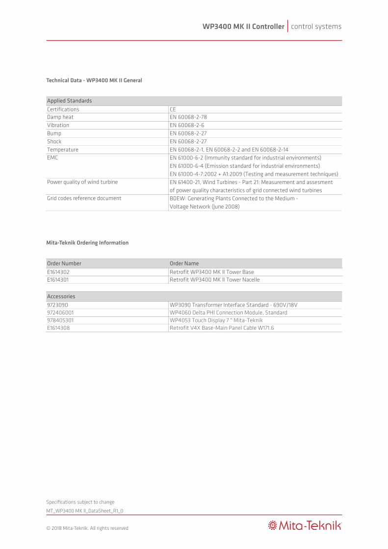
Mita-Teknik Ordering Information
Technical Data - WP3400 MK II General
Order Number Order NameE1614302 Retrofit WP3400 MK ll Tower BaseE1614301 Retrofit WP3400 MK ll Tower Nacelle
Accessories9723090 WP3090 Transformer Interface Standard - 690V/18V972406001 WP4060 Delta PHI Connection Module, Standard978405301 WP4053 Touch Display 7 " Mita-TeknikE1614308 Retrofit V4X Base-Main Panel Cable W171.6
Certifications CEDamp heat EN 60068-2-78Vibration EN 60068-2-6Bump EN 60068-2-27Shock EN 60068-2-27Temperature EN 60068-2-1, EN 60068-2-2 and EN 60068-2-14EMC EN 61000-6-2 (Immunity standard for industrial environments)
EN 61000-6-4 (Emission standard for industrial environments)EN 61000-4-7:2002 + A1:2009 (Testing and measurement techniques)
Power quality of wind turbine EN 61400-21, Wind Turbines - Part 21: Measurement and assesment of power quality characteristics of grid connected wind turbines
Grid codes reference document BDEW: Generating Plants Connected to the Medium - Voltage Network (June 2008)
Applied Standards
control systemsWP3500 MK II Controller
MT_WP3500 MK ll_DataSheet_R3_0
®
© 2018 Mita-Teknik. All rights reserved
Specifications subject to change
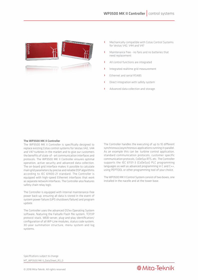
The WP3500 MK II ControllerThe WP3500 MK II Controller is specifically designed to replace existing Cotas control systems for Vestas V42, V44 and V47 turbines in the market and to give our customers the benefits of state-of –art communication interfaces and protocols. The WP3500 MK II Controller ensures optimal operation, active security and advanced data collection. The on-board grid interface makes it possible to calculate main grid parameters by precise and reliable DSP algorithms according to IEC 61400-21 standard. The Controller is equipped with high-speed Ethernet interfaces that work as separate network interfaces. The Controller also features safety chain relay logic.
The Controller is equipped with internal maintenance-free power back-up, ensuring all data is stored in the event of system power failure (UPS shutdown/failure) and program update.
The Controller uses the advanced OS1xx Operating System software, featuring the Failsafe Flash file system, TCP/IP protocol stack, WEB-server, plug-and-play identification/configuration of all WP-Line modules, status code system, 30-year summation structure, menu system and log systems.
The Controller handles the executing of up to 10 different synchronous/asynchronous applications running in parallel. As an example this can be: turbine control application, standard communication protocols, customer specific communication protocols, CoDeSys RTS, etc. The Controller supports the IEC 61131-3 (CoDeSys) PLC programming languages as well as advanced programming in C and C++, using PEPTOOL or other programming tool of your choice.
The WP3500 MK II Control System consist of two boxes, one installed in the nacelle and at the tower base.
› Mechanically compatible with Cotas Control Systems for Vestas V42, V44 and V47 › Maintenance free - no fans and no batteries that need replacement
› All control functions are integrated
› Integrated realtime grid measurement
› Ethernet and serial RS485
› Direct integration with safety system
› Advanced data collection and storage
control systemsWP3500 MK II Controller
MT_WP3500 MK ll_DataSheet_R3_0
®
© 2018 Mita-Teknik. All rights reserved
Specifications subject to change
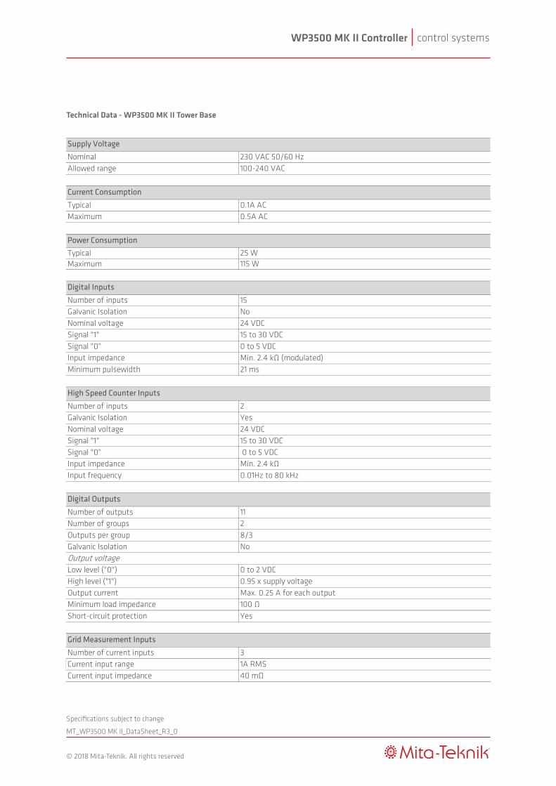
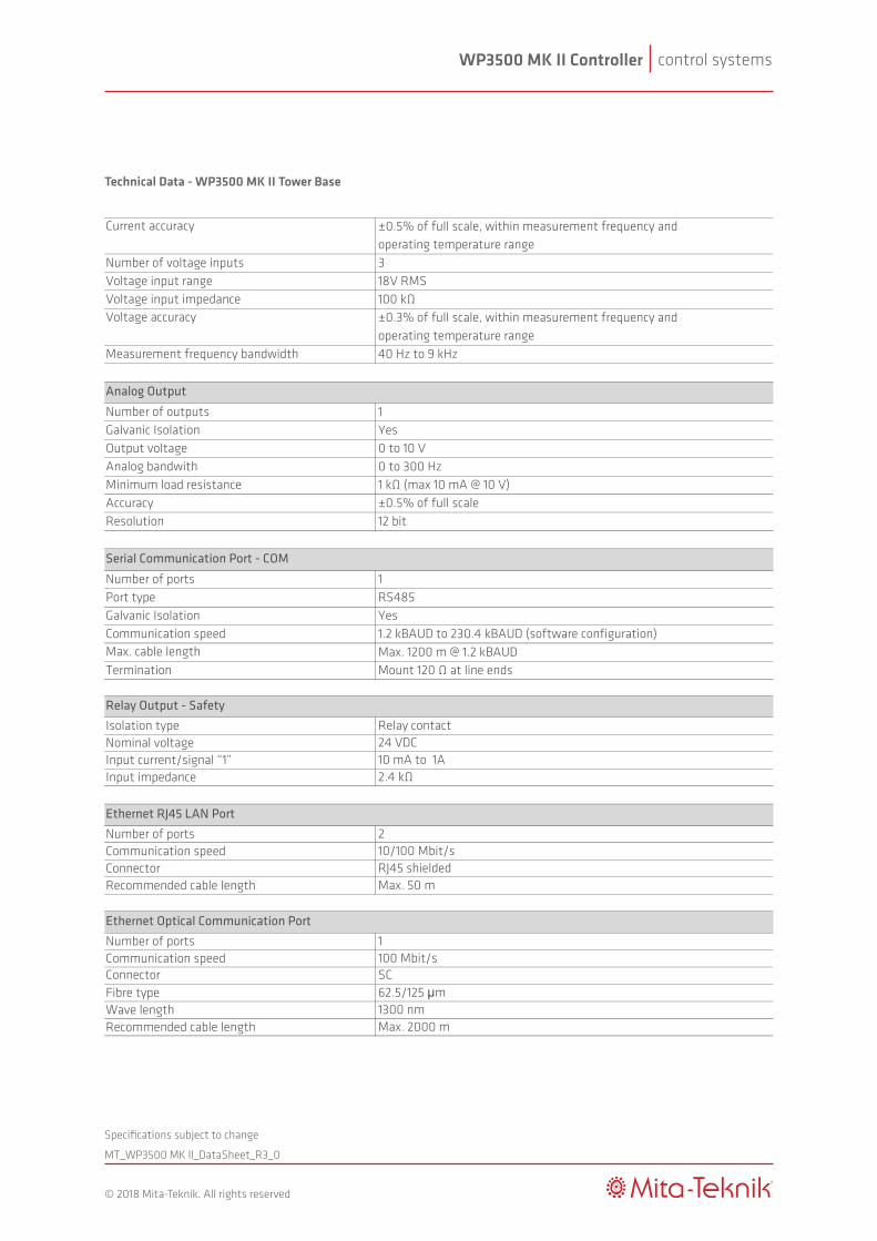
Technical Data - WP3500 MK II Tower Base
Nominal 230 VAC 50/60 HzAllowed range 100-240 VAC
Typical 0.1A ACMaximum 0.5A AC
Typical 25 WMaximum 115 W
Number of inputs 15Galvanic Isolation NoNominal voltage 24 VDCSignal "1" 15 to 30 VDCSignal "0" 0 to 5 VDCInput impedance Min. 2.4 kΩ (modulated)Minimum pulsewidth 21 ms
Number of inputs 2Galvanic Isolation YesNominal voltage 24 VDCSignal "1" 15 to 30 VDCSignal "0" 0 to 5 VDCInput impedance Min. 2.4 kΩInput frequency 0.01Hz to 80 kHz
Number of outputs 11Number of groups 2Outputs per group 8/3Galvanic Isolation NoOutput voltageLow level ("0") 0 to 2 VDCHigh level ("1") 0.95 x supply voltageOutput current Max. 0.25 A for each outputMinimum load impedance 100 ΩShort-circuit protection Yes
Number of current inputs 3Current input range 1A RMSCurrent input impedance 40 mΩ
Supply Voltage
Current Consumption
Grid Measurement Inputs
High Speed Counter Inputs
Digital Outputs
Digital Inputs
Power Consumption
control systemsWP3500 MK II Controller
MT_WP3500 MK ll_DataSheet_R3_0
®
© 2018 Mita-Teknik. All rights reserved
Specifications subject to change
Technical Data - WP3500 MK II Tower Base
Current accuracy ±0.5% of full scale, within measurement frequency andoperating temperature range
Number of voltage inputs 3Voltage input range 18V RMSVoltage input impedance 100 kΩVoltage accuracy ±0.3% of full scale, within measurement frequency and
operating temperature rangeMeasurement frequency bandwidth 40 Hz to 9 kHz
Number of outputs 1Galvanic Isolation YesOutput voltage 0 to 10 VAnalog bandwith 0 to 300 HzMinimum load resistance 1 kΩ (max 10 mA @ 10 V)Accuracy ±0.5% of full scaleResolution 12 bit
Number of ports 1Port type RS485Galvanic Isolation YesCommunication speed 1.2 kBAUD to 230.4 kBAUD (software configuration)Max. cable length Max. 1200 m @ 1.2 kBAUDTermination Mount 120 Ω at line ends
Isolation type Relay contactNominal voltage 24 VDCInput current/signal “1” 10 mA to 1AInput impedance 2.4 kΩ
Number of ports 2Communication speed 10/100 Mbit/sConnector RJ45 shieldedRecommended cable length Max. 50 m
Number of ports 1Communication speed 100 Mbit/sConnector SCFibre type 62.5/125 μmWave length 1300 nmRecommended cable length Max. 2000 m
Ethernet RJ45 LAN Port
Relay Output - Safety
Serial Communication Port - COM
Analog Output
Ethernet Optical Communication Port
control systemsWP3500 MK II Controller
MT_WP3500 MK ll_DataSheet_R3_0
®
© 2018 Mita-Teknik. All rights reserved
Specifications subject to change
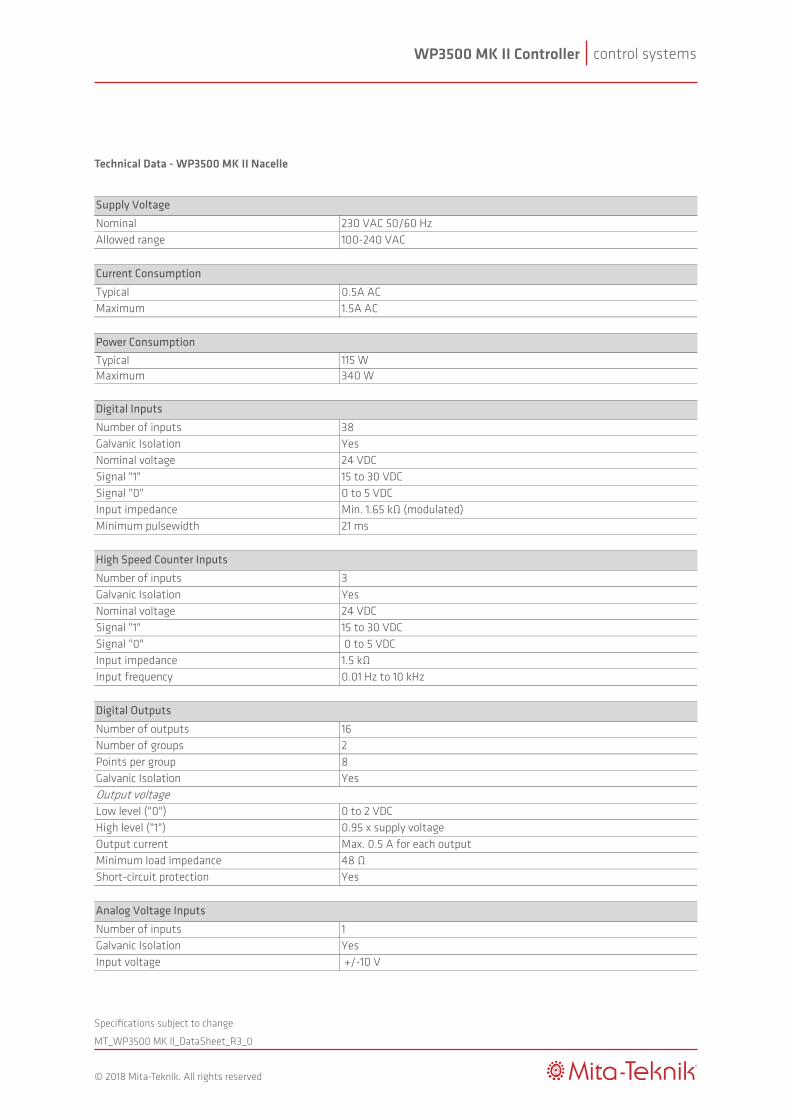
Technical Data - WP3500 MK II Nacelle
Nominal 230 VAC 50/60 HzAllowed range 100-240 VAC
Typical 0.5A ACMaximum 1.5A AC
Typical 115 WMaximum 340 W
Number of inputs 38Galvanic Isolation YesNominal voltage 24 VDCSignal "1" 15 to 30 VDCSignal "0" 0 to 5 VDCInput impedance Min. 1.65 kΩ (modulated)Minimum pulsewidth 21 ms
Number of inputs 3Galvanic Isolation YesNominal voltage 24 VDCSignal "1" 15 to 30 VDCSignal "0" 0 to 5 VDCInput impedance 1.5 kΩInput frequency 0.01 Hz to 10 kHz
Number of outputs 16Number of groups 2Points per group 8Galvanic Isolation YesOutput voltageLow level ("0") 0 to 2 VDCHigh level ("1") 0.95 x supply voltageOutput current Max. 0.5 A for each outputMinimum load impedance 48 ΩShort-circuit protection Yes
Number of inputs 1Galvanic Isolation YesInput voltage +/-10 V
Supply Voltage
Current Consumption
Analog Voltage Inputs
High Speed Counter Inputs
Digital Outputs
Digital Inputs
Power Consumption

control systemsWP3500 MK II Controller
MT_WP3500 MK ll_DataSheet_R3_0
®
© 2018 Mita-Teknik. All rights reserved
Specifications subject to change
Technical Data - WP3500 MK II Nacelle
Measurement precision +/-50 mVInput frequency 0-100 HzResolution 12 bitInput impedance 37.5 kΩ
Number of inputs 2Galvanic Isolation YesInput current 0-20 mAMeasurement precision +/-50 µAInput frequency 0-100 HzResolution 12 bitImput impedance 250 Ω
Number of inputs 10Galvanic Isolation YesMeasuring range -60°C to +230°CAccuracy +/-0.5°CResolution 0.1°CInput impedance 10kΩ (current max. 1 mA)
Number of outputs 1Galvanic Isolation YesOutput voltage +/-10 VAnalog bandwith 0 to 300 HzMinimum load resistance 1kΩ (max 10 mA @ 10 V)Accuracy ±0.39 mVResolution 12 bitShort-circuit protection Yes
Number of ports 2Port type RS485Galvanic Isolation YesCommunication speed 1.2 kBAUD to 230.4 kBAUD (software configuration)Max. cable length Max. 1200 m @ 1.2 kBAUD
Number of ports 1Communication speed 10/100 Mbit/sConnector RJ45 shieldedRecommended cable length Max. 50 m
Analog Voltage Outputs
PT100 Inputs
Analog Current Inputs
Ethernet RJ45 LAN Port
Serial Communication Port - COM
control systemsWP3500 MK II Controller
MT_WP3500 MK ll_DataSheet_R3_0
®
© 2018 Mita-Teknik. All rights reserved
Specifications subject to change
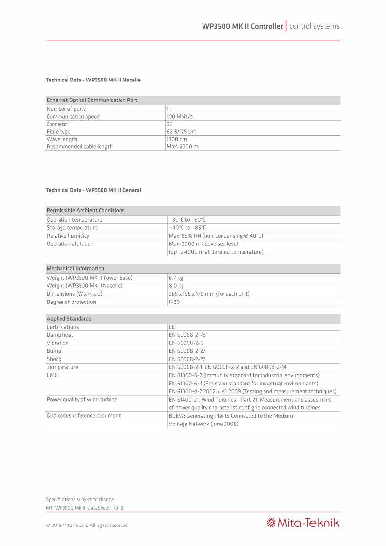
Technical Data - WP3500 MK II Nacelle
Number of ports 1Communication speed 100 Mbit/sConnector SCFibre type 62.5/125 μmWave length 1300 nmRecommended cable length Max. 2000 m
Ethernet Optical Communication Port
Technical Data - WP3500 MK II General
Operation temperature -30°C to +50°CStorage temperature -40°C to +85°CRelative humidity Max. 95% RH (non-condensing @ 40°C)Operation altitude Max. 2000 m above sea level
(up to 4000 m at derated temperature)
Weight (WP3500 MK II Tower Base) 6.7 kgWeight (WP3500 MK II Nacelle) 8.0 kgDimensions (W x H x D) 365 x 195 x 170 mm (for each unit)Degree of protection IP20
Certifications CEDamp heat EN 60068-2-78Vibration EN 60068-2-6Bump EN 60068-2-27Shock EN 60068-2-27Temperature EN 60068-2-1, EN 60068-2-2 and EN 60068-2-14EMC EN 61000-6-2 (Immunity standard for industrial environments)
EN 61000-6-4 (Emission standard for industrial environments)EN 61000-4-7:2002 + A1:2009 (Testing and measurement techniques)
Power quality of wind turbine EN 61400-21, Wind Turbines - Part 21: Measurement and assesment of power quality characteristics of grid connected wind turbines
Grid codes reference document BDEW: Generating Plants Connected to the Medium - Voltage Network (June 2008)
Applied Standards
Permissible Ambient Conditions
Mechanical Information
control systemsWP3500 MK II Controller
MT_WP3500 MK ll_DataSheet_R3_0
®
© 2018 Mita-Teknik. All rights reserved
Specifications subject to change
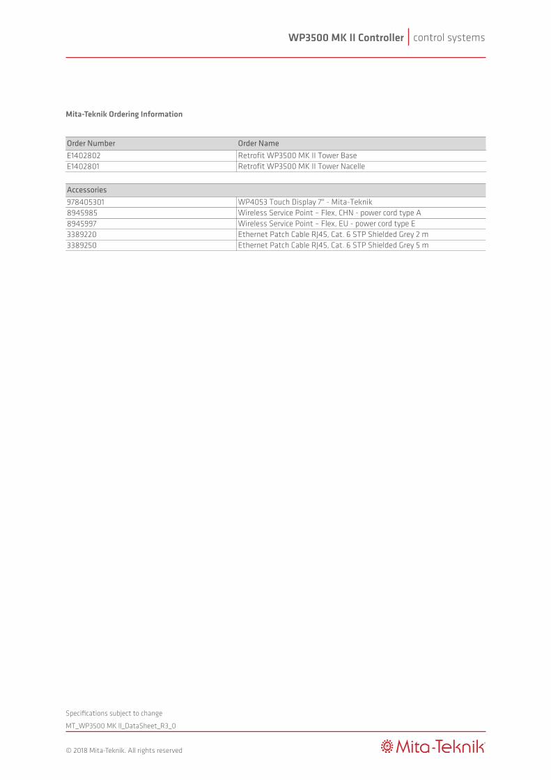
Mita-Teknik Ordering Information
Order Number Order NameE1402802 Retrofit WP3500 MK II Tower BaseE1402801 Retrofit WP3500 MK II Tower Nacelle
Accessories978405301 WP4053 Touch Display 7" - Mita-Teknik8945985 Wireless Service Point – Flex, CHN - power cord type A8945997 Wireless Service Point – Flex, EU - power cord type E3389220 Ethernet Patch Cable RJ45, Cat. 6 STP Shielded Grey 2 m3389250 Ethernet Patch Cable RJ45, Cat. 6 STP Shielded Grey 5 m