world tunnel congress 2010, vancouver, canada, 14-20 may
TRANSCRIPT

World Tunnel Congress 2010, Vancouver, Canada, 14-20 May 2010 (VII.00087.01.EN)
102.1-R-231 1
The Gibraltar Tunnel: The Design Revision
A. Panciera1, A. Bensaid2, F. Roca3
1Lombardi Ltd, Minusio, Switzerland; 2Société Nationale pour les Etudes du Détroit de Gibraltar (SNED), Rabat, Maroc; 3Sociedad Espagnola de estudios para la Comunicación fija a través del
Estrecho de Gibraltar (SECEG), Madrid, Spain 1. The project Thirty years ago, in 1980, the Kings of Morocco and Spain signed the treaty for bringing a vision into reality: the realisation of the fixed link between the two countries, and the two continents Africa and Europe. The heavy traffic in the strait of Gibraltar and the often difficult conditions for shipping are reasons for a fixed link. Two lead companies were created as a result of this treaty: – SNED (Société Nationale d’Etude du Détroit) in Morocco and – SECEG (Sociedad española de Estudios para la Comunicación fija a través del Estrecho de
Gibraltar) in Spain. The bathygraphic survey of the entire strait was the initial step. After detailed studies of the sea depths, a particular corridor was recognised as the most advantageous. At the narrowest point, the sea is about 900 m deep, whereas the minimum depth of only 300 m can be found along the so-called "Route du seuil" (the crest path). This location is considered as the only one possible for any sort of project, be it a bridge or a tunnel. The location of the project and the alignment (Fig. 1) are a compromise between the width of the channel, the sea depth, the need to avoid previously drilled deep boreholes possibly causing uncontrolled water intake and the required ramp gradients and lengths for descending to the lowest point. Such a depth remains a unequalled limit for existing and presently expected projects through straits. Fig. 1: Location and route of the project A connection by bridge is not feasible because of technical limits and service aspects that have become more restrictive in the last years. The piers would be 800 m high. A few months ago, the first structure of this height worldwide was inaugurated in Dubai. Risks of collisions and terrorist attacks remain uncontrollable. For these reasons, the tunnel became the only choice, and its feasibility was studied in detail, resulting in a preliminary design dated 1996.

World Tunnel Congress 2010, Vancouver, Canada, 14-20 May 2010 (VII.00087.01.EN)
102.1-R-231 2
2. The Tunnel, its geology and its revision The 1996 tunnel design (APP96) had to be revised because of unexpected geological conditions (Fig. 2) encountered at the time of additional investigations, using deep sea core drilling (Fig. 2 left), and because of the long term behaviour (swelling rock) observed in the Malabata Shaft (Fig. 2 right). The Malabata exploratory system consists of 2 subsequent 150 m deep shafts and a series of 3 m diameter galleries (test chambers 5 m). It is located at the Strait's shores near Tangier, in Morocco. Its excavation dates back to the 90s. After several years of construction and research, the original program was achieved and the shaft abandoned. Recently reopened, the general conditions of this work were found to be very good, except for some significant swelling phenomena (Fig. 2, right).
Fig. 2: The breccias in the middle of the Strait (known 1998-2005) and the swelling (known 2007) The geological forecast along the tunnel indicated a series of subsequent flysch formations. Initially subdivided and differentiated between Spanish and Moroccan formations, these could be unified across the Strait: the Almarchal flysch and the Tangier unit, the Algeciras and the Beni Ider formations, etc.. New investigation techniques used in two subsequent campaigns 1997-9 improved the cored length by 6 times, and yet another campaign in 2005, brought another significant raise of length and information. The geological model had to be completed with the following units: – Lumachella marble limestone and bio-clastic sand: in the first 10 m of depth under the seabed,
but not evenly distributed over the entire width of the channel. Possible origin: a coral platform and the product of its erosion.
– Breccia (Fig. 2, left): a chaotic mixture of blocks, stones and stone splinters bedded in a clay matrix, which can comprise more than 40 % of the whole, extending into yet unknown depths under the seabed, but certainly beyond the intended depth of the tunnel according to the 1995 preliminary design.
These unexpected geological findings (Fig. 3, in the centre) required a major design revision.
Fig. 3: Updated geological profile through the Strait with core drilling indication

World Tunnel Congress 2010, Vancouver, Canada, 14-20 May 2010 (VII.00087.01.EN)
102.1-R-231 3
Besides, the presence of several boreholes near the chosen alignment required its revision. The working conditions in the middle of the Strait are severe. The final grouting of the drillings was difficult and not certified. The collapse of such a hole when intercepted or only approached by the tunnel excavation is a major hazard that no one can accept. The revised alignment (Fig. 4) cannot exceed the "route du seuil" but assure a minimum horizontal distance from the drillings, for considering possible deviations and a minimum safe gradient from the hole to the tunnel.
Fig. 4: Present tunnel alignment A major risk remains the invasion of the cavity by water from the seabed. The upper 100 m of bio-clastic sands in the middle of the Strait have to be considered as fully permeable, therefore not useful as an efficient barrier against this risk. At 500 m depth, 100 m quite impervious breccias create the required barrier, assuring the expected maximum gradient. At a deeper location, even if hydraulically desirable, the length of the ramps and the cost related aspects become quickly unbearable. Increased length means higher construction costs, (also due to increases security requirements), a generally longer construction time and heavier investment plans. The presently adopted slope of 3% lies clearly at the limit of suitability. The mere application of current European standards for long railways tunnels would ask for 27-40 km long ramps and a related total tunnel length of approx. 60-85 km, de facto a 50 to 100% longer tunnel. Considering the results of specific studies at the time of the previous design phase, 3% slopes were adopted as a correct and acceptable compromise between the high geomechanical and hydraulic risks, resulting in high costs per km, and the maintenance and energetic cost, the reduction of which due to less consumption per km would be compensated by the longer cost-intensive ramps. Investment cost considerations are herein not considered by the engineer, surely fundamental for the Client. The resulting longitudinal profile (Fig. 5) considers and represents all these aspects, showing also the possibility for the initial access of the investigation tunnel, the "descenderie".
Fig. 5: Longitudinal profile with simplified geological features
LAND 50 100 200 300 400 500 600 700
SPAIN
CURVES EVERY 50 m, ZONES EVERY 100 m
MOROCCO

World Tunnel Congress 2010, Vancouver, Canada, 14-20 May 2010 (VII.00087.01.EN)
102.1-R-231 4
3. The geomechanical aspects, modelling and computations 3.1. General conditions The breccias, its low properties and complex constitutive law, the coupled hydraulic conditions and the need for considering a running or stopped TBM drive, represent the greatest challenge. Along with the initial 2D computations, it became clear that the advance could occur only by the use of a TBM with pressure compensation at the excavation face: Earth Pressure Balance TBM (EPB) or Hydroshield. Because of the nature and consistency of the rock (high clay content) and the extremely high acting water pressure to be compensated for avoiding the extrusion of the excavation face, no intervention could be considered as sufficiently safe in case of conventional excavation methods. Only freezing could fit the requirements for realising the by-passes but impossible to be adopted for the main advances because of cost and time related aspects. Additional measures had to be integrated into the TBM project for enabling its operation: – Possibility for high radial deformations, to be achieved through overcutting, tapered boring and
annular gap with altogether radial 40 cm from the face to the outer segments diameter, – High working pressure in the excavation chamber (up to at least 10 bar, better higher), – Targeted drilling for the purpose of investigation, drainage and consolidation.
Such properties are of a decisive importance for the geomechanical calculations and are all integrated in the computation model, especially for the 3D calculations. The decisive geometrical conditions are found in the middle of the Strait, and also apply for a stretch about 5 to 6 km long through breccia and flysch formations, where the natural stress state is unusual. The water pressure (500 m head of water) is higher than the effective stress (200 m rock with a dead weight considerably less than 25 kN/m3).
u = 5′000 kPa (500 t/m2), σ′ = 200 · (2,2–1) = 2,400 kPa (240 t/m2), σtot = u + σ′ = 7,400 kPa = 7.4 MPa (740 t/m2)
Because the results of a computation in total stress state lead to errors, coupled analyses have to be included in the method in such complex cases. 3.2. 2D model The first computations were performed with 2D models according to the usual slice model for the tunnel cross-section and a hemispherical shape of the working face. All analyses considered the equilibrium of the total and effective stresses as well as the effects of drainage and consolidation. This was achieved through the use of the constitutive model according to Biot and the related Skempton coefficient [1]. Calculations in the total stress condition do not allow the flow forces and their effect on the stability and the deformations of the cavity to be evaluated without errors. The usual approach through the increasing of the cohesion results in the underestimation of significant destabilising effects. The computations confirm the requirements for the stabilising pressure at the face and the working pressure in the excavation chamber respectively. These should reach the range of 1'200 to 1'830 kPa, a high value according to the current state of technology. The loading process between working face and a state of equilibrium on the segments is of fundamental importance. In the present case, the minimum stabilising pressure should act continuously all along the shield up to the installed precast elements. Therefore, given such complex conditions where total and effective stresses and the associated flow forces and consolidation processes play a significant role, improved models need to be developed. The calculations were performed with the programme FLAC-2D with an axially symmetrical layout of the model, which simulates well the 3D conditions of a TBM drive in a homogeneous rock mass. The most unfavourable conditions were assumed as the basis for the model. On account of the great length of tunnel in flysch, this formation was analysed in addition to breccia.
World Tunnel Congress 2010, Vancouver, Canada, 14-20 May 2010 (VII.00087.01.EN)
102.1-R-231 5
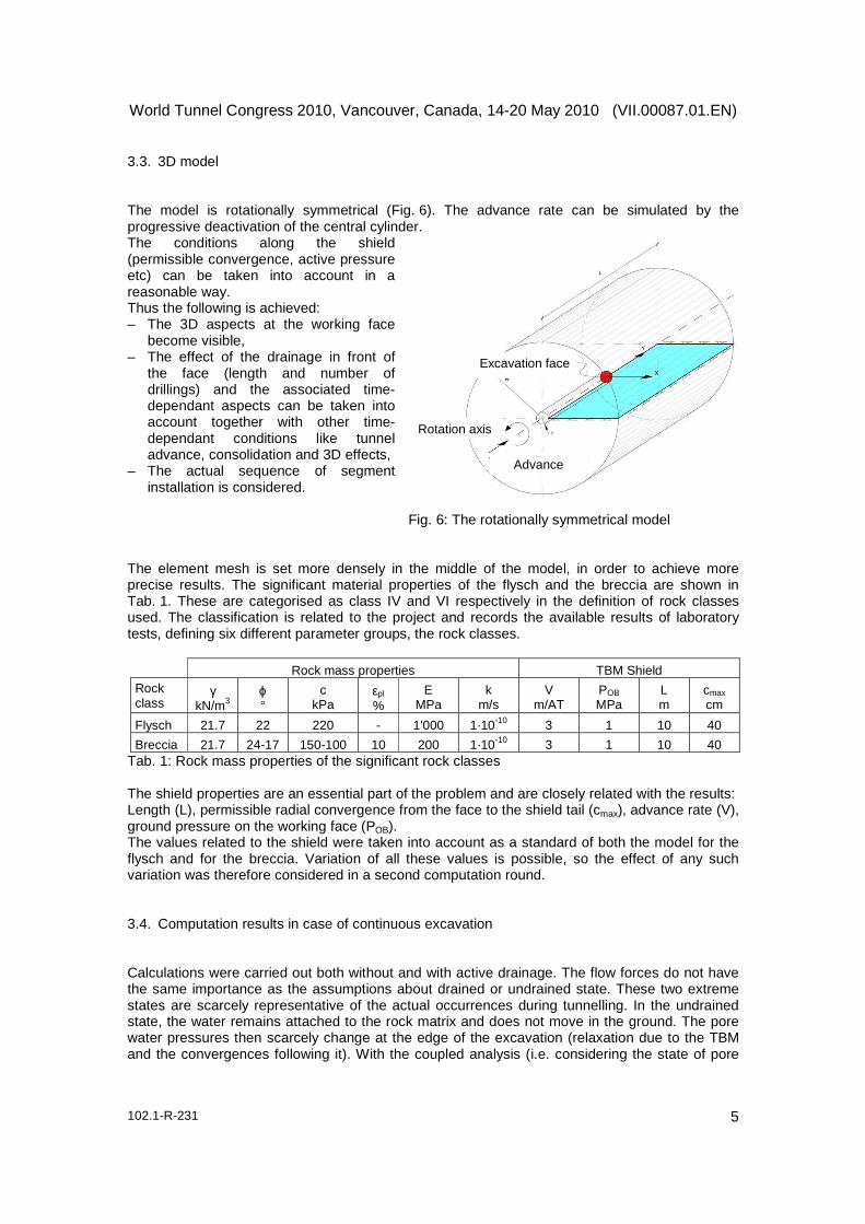
3.3. 3D model The model is rotationally symmetrical (Fig. 6). The advance rate can be simulated by the progressive deactivation of the central cylinder. The conditions along the shield (permissible convergence, active pressure etc) can be taken into account in a reasonable way. Thus the following is achieved: – The 3D aspects at the working face
become visible, – The effect of the drainage in front of
the face (length and number of drillings) and the associated time-dependant aspects can be taken into account together with other time-dependant conditions like tunnel advance, consolidation and 3D effects,
– The actual sequence of segment installation is considered.
Fig. 6: The rotationally symmetrical model The element mesh is set more densely in the middle of the model, in order to achieve more precise results. The significant material properties of the flysch and the breccia are shown in Tab. 1. These are categorised as class IV and VI respectively in the definition of rock classes used. The classification is related to the project and records the available results of laboratory tests, defining six different parameter groups, the rock classes.
Rock mass properties TBM Shield Rock class
γ kN/m3
ϕ °
c kPa
εpl %
E MPa
k m/s
V m/AT
POB MPa
L m
cmax cm
Flysch 21.7 22 220 - 1'000 1·10-10 3 1 10 40
Breccia 21.7 24-17 150-100 10 200 1·10-10 3 1 10 40 Tab. 1: Rock mass properties of the significant rock classes The shield properties are an essential part of the problem and are closely related with the results: Length (L), permissible radial convergence from the face to the shield tail (cmax), advance rate (V), ground pressure on the working face (POB). The values related to the shield were taken into account as a standard of both the model for the flysch and for the breccia. Variation of all these values is possible, so the effect of any such variation was therefore considered in a second computation round. 3.4. Computation results in case of continuous excavation Calculations were carried out both without and with active drainage. The flow forces do not have the same importance as the assumptions about drained or undrained state. These two extreme states are scarcely representative of the actual occurrences during tunnelling. In the undrained state, the water remains attached to the rock matrix and does not move in the ground. The pore water pressures then scarcely change at the edge of the excavation (relaxation due to the TBM and the convergences following it). With the coupled analysis (i.e. considering the state of pore
Rotation axis
Advance
Excavation face

World Tunnel Congress 2010, Vancouver, Canada, 14-20 May 2010 (VII.00087.01.EN)
102.1-R-231 6
water pressure and of the effective stresses separated from each other) on the other hand, in the undrained and also in the drained state meaningful alterations of the pore water pressure and meaningful flow forces can be detected, even if no drainage is effective, as a consequence of the application of the Biot model. The same hydrostatic and geotechnical assumptions were made for each computation pair: – Model size: 50 m radius and 80 m length, – 10 bar (1 MPa) hydrostatic pressure at the machine and along the shield, – 50 bar (5 MPa = 500 m water head) hydrostatic pressure constant for the entire computation
course with limitless storage; the balancing of the pore pressure occurs in the model, – 2.4 MPa (= 200 m ground) effective pressure around the model, – Only radial deformations permitted at the edge of the model.
When it comes to the pore pressure (Fig. 7), the relaxation of the natural conditions around the shield is visible. The essential difference with or without active drainage is the consolidation of a ring around the face before excavation. The core is not intensively drained on account of its very low permeability. The effective resistance of the formation is however mobilised and the flow forces near the face are considerably reduced. An improvement of the drainage effect is possible, but all aspects of the construction (time, required machinery) have to be considered. Fig. 7: Breccia, water pressure distribution, effect of the drainage
The influence of the drainage is also clear through the comparison of the extent of the plastic zone. This shows the usual arch shape with a radius of more than 40 m in the case without active drainage (Fig. 8, left) but less than 30 m with active drainage (Fig. 8, right).
Fig. 8: Breccia, extension of the plastic zone, effect of the drainage
World Tunnel Congress 2010, Vancouver, Canada, 14-20 May 2010 (VII.00087.01.EN)
102.1-R-231 7
The radial convergences along the tunnel profile clearly show (Fig. 9) that equilibrium has been reached. The 3D computations confirm the results. In the case that no drainage is active (Fig. 9, left), the developed radial convergence is already 80 cm from the face until the installed segment ring blocking any further deformation. No tapering of the shield can make possible such radial convergences. At the opposite, when the drainage is active (Fig. 9, right), the radial convergence is less 30 cm from the face until the installed segment ring. The shield tapering is reasonably possible within the conditions resulting from this second computation.
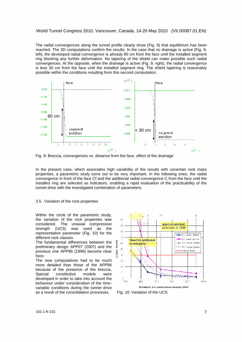
Fig. 9: Breccia, convergences vs. distance from the face, effect of the drainage In the present case, which associates high variability of the results with uncertain rock mass properties, a parametric study turns out to be very important. In the following ones, the radial convergence in front of the face Cf and the additional radial convergence C from the face until the installed ring are selected as indicators, enabling a rapid evaluation of the practicability of the tunnel drive with the investigated combination of parameters. 3.5. Variation of the rock properties Within the circle of the parametric study, the variation of the rock properties was considered. The uniaxial compressive strength (UCS) was used as the representative parameter (Fig. 10) for the different rock classes. The fundamental differences between the preliminary design APP07 (2007) and the previous one APP96 (1996) become clear here. The new computations had to be much more detailed than those of the APP96 because of the presence of the breccia. Special constitutive models were developed in order to take into account the behaviour under consideration of the time-variable conditions during the tunnel drive as a result of the consolidation processes. Fig. 10: Variation of the UCS
80 cm
< 30 cm

World Tunnel Congress 2010, Vancouver, Canada, 14-20 May 2010 (VII.00087.01.EN)
102.1-R-231 8
The 3D calculations were very challenging because of the simulation of the advance under the condition of a partially supported rock mass along the shield until the total closure of the annular gap on the lining. These calculations confirm that the APP96 was correct, specifically that the tunnel is altogether achievable in the flysch. The presence of the breccias means, in contrast, a considerably higher risk of the shield jamming due to the large convergences. This circumstance demands an adaptation of the tunnelling conditions like effective and continuous drainage as well as the application of a higher pressure on the working face in the order of 15 to 20 bar. 4. Execution aspects The realisation of the tunnels would require approx. 10 years construction time for civil works. The intermediate access to the tunnel central point is possible through the exploratory tunnel (becoming the exhaust gallery in service conditions) and allows the realisation of the Safe Access Zone. The railway systems and all the electromechanical works would take approx. 5 years. The final testing of all works and systems and the related team training (technical, survey, and security personnel) is assumed as an additional 1 year. Total construction time is presently foreseen being in the order of 16 years. Before this phase, the realisation of the exploratory tunnel and the related tests and design activity (optimisation of machinery and solutions to the actual conditions) is estimated taking approx. 8 years. Considering possible unforeseen situations (difficult to be framed, knowing the present limits concerning some aspects of geology, geotechnics, geomechanics and construction techniques) a total construction time of approx. 25 years seems reasonable. The usual range of precision at the stage of preliminary design should be further applied. 5. Conclusions In summary, the following aspects should be emphasised: – The flow forces are decisive for the stability of the cavity. – The effect of the drainage in front of the face is a significant precondition for the reduction of
the flow forces around the cavity. – Increasing the working pressure to over 10 bar (1 MPa) would be desirable. This value does,
however, lie at the outer limit of the present state of the art and has to be seen as a challenge. – The design value for the lining should take into consideration the long-term loads (determined
by water pressure, the residual effective pressure and the swelling of the rock mass). Considering the unknown swelling potential and its limits, this value was assumed as the total natural stress state of 7.4 MPa acting on the lining. As a result of this, 80 to 120 cm thick segments with concrete strengths of the order of 100 MPa would have to be installed.
– Many aspects like the characteristics of the various rock types and the properties of the pore water system, which have a great influence on the results, are still unknown. The determined rock mass characteristics lie to some extent at the limit of practicability of the tunnel.
This means that the driving of an investigation tunnel is unavoidable. The opportunity to unify the initial function of investigation to the one of smoke extraction tunnel in service conditions is highly profitable, considering the recent design standard applied by such extraordinary projects. 6. Bibliography [1] Fr. Amberg, Numerical simulations of tunnelling in soft rock under water pressure, EURO:TUN 2009, 2nd International Conference on Computational Methods in Tunnelling, Ruhr University Bochum, 9th-11th September 2009