wood gasification process
TRANSCRIPT


Wood gasification process.....................................................3
Wood as a fuel ......................................................................3
Boiler construction - its elements ..........................................4
Boiler construction - materials ...............................................4
...................................................................4
Boiler construction - schematics ...........................................5
Boiler dimensions ..................................................................6
Boiler sizeing..........................................................................7
ORLAN SUPER .....................................................................8
Basic information about boiler assembly ...............................8
Boiler interaction with a four-way mixing valve ......................9
Boiler interaction with operational water heater .....................9
Boiler connection scheme - examples ..................................10
Additional equipment:Hydrometer ...........................................................................11
ORLAN SUPER additional equipment:Thermal safety device (cooling coil) .....................................11
Additional equipment:LADDOMAT 21 thermoregulator ..........................................12
EKO advantages
2

Raw wood humidity ranges from 60%(wood cut in winter) to 80% (cut in
summer). Most favorable wood humidityis obtained after 12-18 months of storing.
Wood gasification proces
Wood as a fuel
Gasification process in our central heating boileris divided into 4 stages:
1. Drying and release of wood gases inside theloading chamber in slow glowing process.
2. Burning of gas mixture with secondary airin the lower chamber at 2200°F.
3. Flame reheating and heat exchange.
4. Combustion gases ejecting through chimney flueafter the boiler will reach desized oprationaltem-perature.
Wood is a renewable resource like solar, water, orwind power. They are all energy sources, whichnever become depleted, unless improperlymanaged. Wood is also a fuel, which may be storedand preserved without energy loss. Wood storingreduces its moisture and simultaneously increasesits heating value (energy volume, which may be usedup during burning process).
Modern boilers utilizing wood in gasificationprocesses use energy contained in wood withefficiency that is three times higher than traditionalboilers. Smoke and other emissions are cut to a verylow level, making our boilers very nature friendly.
ORLAN boilers are adapted for burning of any kind ofwood ranging from sawdust to chunks of wood. Thebest way to achieve recommended wood humidity isto cut the timber during springtime, and let it seazonunder a covering like a wood shed or a trap.
The best indicator ofsuccessful wood gasification is the lack ofsmoke exiting the chimney.
3
Burning Zones
Wood too dry (less than 15%)or too wet (more than 25%)
will reduce boiler efficiency.
Best humidi ty forgasification should be
in 20% range.
STAGE 4Ejecting combustiongases throughsmoke stack
STAGE 1Wood dryingand breakdowninto gases
STAGE 2Burning of mixedwood gases withsecondary air
STAGE 3Releasing heattrough heatexchanger
DRYING ZONE
CARBONIZATION ZONE
OXIDATION ZONEREDUCTION ZONE
STAGE 4
STAGE 1
STAGE 2
STAGE 3

Boiler construction - its elements
Sealed wood gasification chamber
nozzle
Exhaust reheat space
smoke tube heat exchangerfan
Safe guard thermostat
Steel turbulators
that is simultaneously used as a loadingchamber. When appropriate amount of primary air supplied by the pressure fan is de-livered, wood gas is generatedA , made of refractory concrete, mixes wood gases with the secondary air and aflammable mixture is produced that undergoes self-ignition at about 1000°F
- the main combustion chamber, where temperature reaches about2000°F serves as an ash pitA (flue gas to water) heats up the installation waterA that communicates with the microchip controller monitors the quality of the whole burningprocess
- each boiler is equipped with an additional safe guard thermostat, whichswitches off the fan while the water gets up to 180°F
in heat exchanger tubes.
4
Boiler construction - materials
Boiler body
Heat exchangerInsulation
NozzleChimney flap
Boiler regulator
Chimney flue -Ash pit
Boiler door
- boiler casing is made of welded metal sheets that are 1/4 inch thick, whereas theremaining walls are 1/16 inch thick.
- smoke tube heat exchanger made of tube with dimensions 2 1/5 inch x x1/16 inch- boiler thermal insulation is composed of glass wool of Nobasil 3/4 inch thick, while the
external casing consists of metal sheet panels 0.8mm thick (powder painted)- ceramic element made of refractory concrete (working temp. up to 2100°F)
- made of high quality steel. Tight flap adhesion to the combustion duct assuresthe burning chamber tightness
- placed on upper boiler cover. The regulator is fixed to the boiler coverby stuck catch
made of 1/14 inch steel tube- steel bottom of the burning chamber, ceramic ash pit added (working temp. ) and
additionally covered by refractory concrete- produced of high quality steel, insulated with Nobasil thermal insulation and inside covered
by refractory concrete layer.Also protected with heat-resisting fiberglass cord.
2100°F
EKO advantages
Orlan boilers are produced as:with cooling coil and mechanical
cleaning device
efficiency 91% (ORLAN 18-85%)ow exploitation costseasy and simple servicesmall quantity of ashone loading for 8÷12 hourspower range from 85 kBtu up to 275 kBtupower modulation from 40÷100%adapted for forced (pump) systemequipped with electronic regulator and roomtemperatur sensornature friendlyproduced of boiler steel
ORLAN SUPER
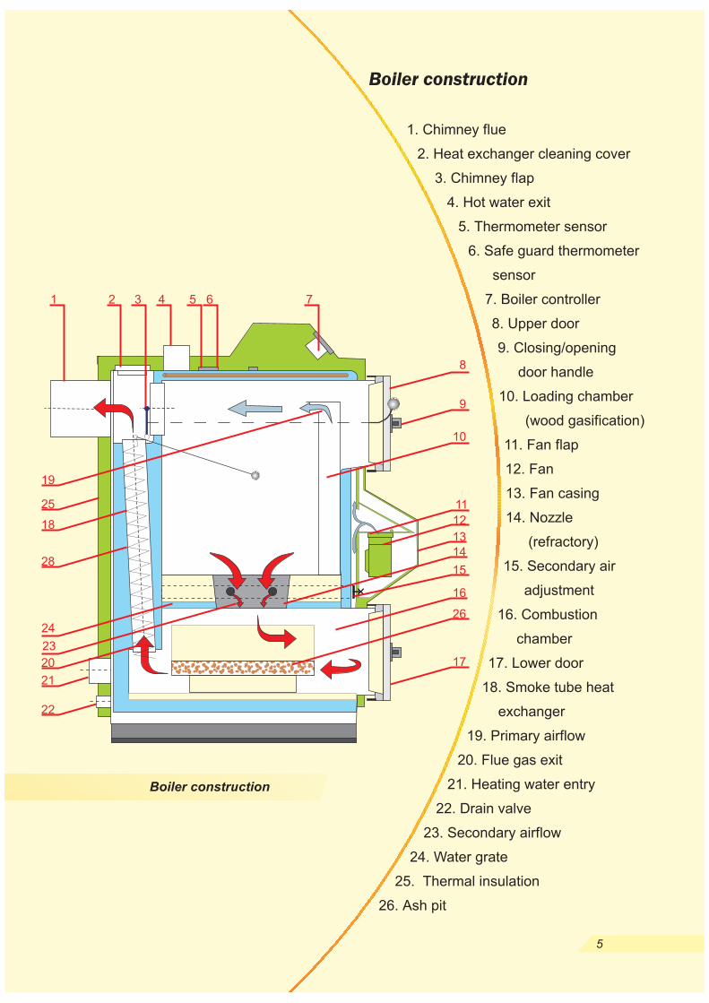
Boiler construction
1. Chimney flue
2. Heat exchanger cleaning cover
3. Chimney flap
4. Hot water exit
5. Thermometer sensor
6. Safe guard thermometer
sensor
7. Boiler controller
8. Upper door
9. Closing/opening
door handle
10. Loading chamber
(wood gasification)
11. Fan flap
12. Fan
13. Fan casing
14. Nozzle
(refractory)
15. Secondary air
adjustment
16. Combustion
chamber
17. Lower door
18. Smoke tube heat
exchanger
19. Primary airflow
20. Flue gas exit
21. Heating water entry
22. Drain valve
23. Secondary airflow
24. Water grate
25. Thermal insulation
26. Ash pit
5
Boiler construction
1 2 3 4 5 6 7
9
8
10
11
12
13
14
15
16
17
22
21
20
24
23
19
18
28
25
26

Boiler dimensions
Boiler dimensions scheme
6
25
85
1080
51.5
48.5
8.3
5.1
37.4
24.8
23.6
41.1
12.6
7.8
2.0
2.0
thread
0.5
20
31
35
7
20
40
137
1212
59
56
6.0
2.7
50.0
24.8
23.6
41.1
12.6
7.8
2.0
2.0
thread
0.5
25
49
35
7
20
460
60
205
1808
60.5
56.5
7.9
5.1
45.7
30.3
29.1
53.5
24.0
8.2
2.5
2.5
flange
0.5
47
82
55
7
25
80
275
2315
60.5
56.5
7.9
5.1
45.7
30.3
29.1
52.7
24.0
8.2
2.5
2.5
flange
0.5
54
123
55
7
39
ORLAN
kBtu
Lb
A inch
B inch
C inch
D inch
E inch
F inch
G inch
H inch
I inch
J mm
inch
inch
-
inch
Gal
Gal
W
%
%
inch
inch
F
PSI
Pa
V/Hz
Boiler type
Power range
Weight
Height
Height of heating water exit
Height of heating water entry
Height of outlet valve
Height of chimney flue
Width including handle
Width including casing
Depth
Hot water exit
Diameter of chimney flue
Diameter of hot water exit
Diameter of hot water entry
Kind of connection
Diameter of drain valve
Water capacity
Volume of loading chamber (gasification)
Power consumption
Moisture of wood:
- recommended
- acceptable
Maximum log diameter
Maximum length of logs
Average temperature of flue gas
Max. working pressure
Required chimney draught
Voltage / frequency
25
15 - 20
12V/60Hz
15 - 25
10 - 35

Boiler sizeing
ORLAN boilers may be used for heating any
kind of building. They are mostly used in
o n e - f a m i l y h o u s e s , d r y k i e l n s ,
workshops, halls, or greenhouses.
However, boiler placement is not
limited to these applications; the
above are just examples of where
ORLAN boilers have worked
with success.
Selecting a boiler that ad-
equately fits ones output is
very important. An impro-
perly chosen boiler may
subject the end-user to
unnecessary expen-ses
during boiler usage.
Boiler output should be
based on a building's
heat demand, calculated
by a qualified central
heating designer. To
select the appropriate
boiler, the a/m calculated
value should be increased
by 20%. If this calculation
isn't performed, boiler sizing
may be chosen using the heat
factor in relation to m of
building cubature. Heat factor
values should be determined as
30-50 W/m depending on heat
insulation.
3
3
REMARK!
The scheme is only an example and New
Horizon is not responsible for the wrong
boiler choice.
7
Boiler sizeing
800
750
700
650
600
550
500
450
400
350
300
250
200
150
100
50
0
buildingswell
insulated
buildingsmiddle
insulated
buildingswithout anyinsulation
He
ate
dsu
rfa
ce
[m]
he
igh
t2
,7m
2
25
40
60
80
25
40
60
80
®
25
40®
60®
®
80
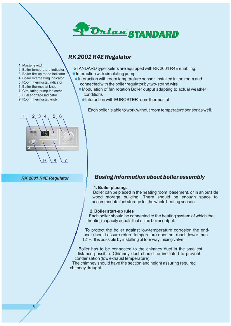
RK 2001 R4E Regulator
Basing information about boiler assembly
STANDARD type boilers are equipped with RK 2001 R4E enabling:
Interaction with circulating pump
Interaction with room temperature sensor, installed in the room and
connected with the boiler regulator by two-strand wire
Modulation of fan rotation Boiler output adapting to actual weather
conditions
Interaction with EUROSTER room thermostat
Each boiler is able to work without room temperature sensor as well.
Boiler can be placed in the heating room, basement, or in an outsidewood storage building. There should be enough space toaccommodate fuel storage for the whole heating season.
Each boiler should be connected to the heating system of which theheating capacity equals that of the boiler output.
To protect the boiler against low-temperature corrosion the end-user should assure return temperature does not reach lower than
12°F. It is possible by installing of four way mixing valve.
Boiler has to be connected to the chimney duct in the smallestdistance possible. Chimney duct should be insulated to prevent
condensation (low exhaust temperature).The chimney should have the section and height assuring required
chimney draught.
1. Boiler placing.
2. Boiler start-up rules
STANDARD
1. Master switch
2. Boiler temperature indicator
3. Boiler fire-up mode indicator
4. Boiler overheating indicator
5. Room thermostat indicator
6. Boiler thermostat knob
7. Circulating pump indicator
8. Fuel shortage indicator
9. Room thermostat knob
1 2 3 4 5 6
9 8 7
STANDARDSTANDARD
8
RK 2001 R4E Regulator

9
Boiler interaction with four-way
mixing valve
Mixing function
Boiler protection from low temperature corrosion -
Preheating of warm operational water
is related to necessary temperature
changing in central heating system considering outside
temperature changes. For proper boiler operation, a
suitable high temperature inside of gasification chamber
is needed; then the water temperature upon boiler exit will
achieve 140-180°F. Using four-way mixing valve enables
to mix adequate water quantity, heated directly by the
boiler, together with returning water from the system. As
the result, the proper water temperature in the boiler is
attained.
is analogous to mixing function but also functions to
increase temperature of the water returning from system
by mixing of the water directly heated into the boiler.
is related to
necessary disconnecting of system during summer
season. Water is heated in universal pre-heater linked
with the boiler on gravitation.
The central heating system should be closed during
summer by mixing valve switching off, and then fast and
efficient water heating is achieved.
Boiler interaction with operational
water heater
To protect the boiler against overheating, the collector is
needed to gather minimal theoretical boiler output on
gravitation.
For this purpose, the best way is to use operational water
heater together with single function boiler without
charging pump. By this gravitational connection, the
system takes over the minimal boiler output in case of
feeding shortage.
1. Outdoors temp. sensor2. Feeding water temp. sensor3. Four-way mixer DUOMIX C,
DUOMIX AO, DUOMIX P, DUOMIX Z4. MK.CS assisting drive5. Circulating pump6. Room temp. sensor7. Boiler8. Heater9. Operational water heating
10. Differential valve11. Compensating vessel12. Exit for warm operational water13. Cold water entry
8
1
62
5
3
1013
1211
7
9
M4
Low temperature corrosion occurs if
the internal boiler walls are in
contact with combustion gases
having a lower temperature than
the temperature of humidity
causing condensation of the
combustion gases.
If there is more acetic acid
into condensate, the low
temperature process is
more intensive.
Example of boiler’s connectingwith four-way mixing valveAnd water heater
ORLAN boilermodel
Heat collectoroutput
Recommended volumeof the operationalwater pre-heater
Recommendedmixing valve diameter
25406080
17 kBtu27 kBtu51 kBtu
85.5 kBtu
DN 25, DN 32DN 32, DN 40
DN 50DN 50, DN 65
OKCV 42 galOKCV 48 galOKCV 53 galOKCV 53 gal
If the boiler is connected into the forced
(pump) system it has to be protected in case
of power deficiency by adding power backup
unit. If boiler operates in closed loop system
temperature-pressure relief valve has to be
installed!
The best way is to connect a water heater
into the heating system, which works
together with boiler without pump service.
This gravitational arrangement enables
collecting of boiler minimal output during
power deficiency.
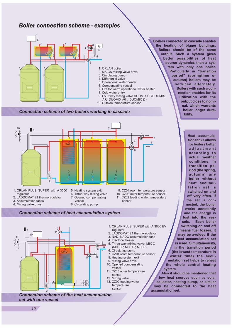
Boiler connection scheme - examples
1. ORLAN boiler2. MK.CS mixing valve drive3. Circulating pump4. Differential valve5. Operational water heater6. Compensating vessel7. Exit for warm operational water heater8. Cold water entry9. Four-way mixing valve DUOMIX C (DUOMIX
AP, DUOMIX A0 , DUOMIX Z )10. Outside temperature sensor
1. ORLAN PLUS, SUPER with A 3000 EVregulator
2. LADDOMAT 21 thermoregulator3. NAD, NADO accumulation tank4. Electrical heater5. Three-way mixing valve MIX C
(MIX BP, MIX AP, MIX P)6. Circulating pump7. CZ04 room temperature sensor8. Heating system exit9. Mixing valve drive
10. Opened compensatingvessel
11. CZ03 outer temperaturesensor
12. Mixing valve13. CZ02 feeding water
temperaturesensor
Connection scheme of two boilers working in cascade
Connection scheme of heat accumulation system
1. ORLAN PLUS, SUPER with A 3000regulator
2. LADDOMAT 21 thermoregulator3. Accumulation tanks4. Mixing valve drive
5. Heating system exit6. Three-way mixing valve7. Opened compensating
vessel8. Circulating pump
9. CZ04 room temperature sensor10. CZ03 outer temperature sensor11. CZ02 feeding water temperature
sensor
109
2
3 3 3
CWU
7
M4
8
11
5
61
LA
DD
OM
AT
21
LA
DD
OM
AT
21
11
7
2
CWU
10
M
9
68
51
3
LA
DD
OM
AT
21
LA
DD
OM
AT
21 4
220V380V
12
13
1
3
4
5
6
7
8
9
10
R
1
28
7
5
Connection scheme of the heat accumulation
set with one vessel
Boilers connected in cascade enables
the heating of bigger buildings.
Boilers should be of the same
output. Such a system gives
better possibilities of heat
source dynamics than a sys-
tem with only one boiler.
Particularly in "transition
period" (springtime or
autumn) boilers may be
serviced alternately.
Boilers with such a con-
nection enables for its
utilization with the
output close to nomi-
nal, which warrants
boiler longer dura-
bility.
Heat accumula-
tion tanks allows
for boilers better
a d j u s t m e n t
according to
actual weather
conditions. In
transition pe-
riod (the spring,
autumn) any
boiler without
heat accumu-
la t ion set is
switched on and
off very often. If
the set is con-
nected, the boiler
works constantly
and the energy is
lost into the ves-
sels. Each boiler
switching on and off
means fuel losses. It
may be avoided if the
heat accumulation set
is used. Simultaneously,
in the transition period
(the lowest temperature in
winter time) the accu-
mulation set helps to reheat
the whole central heating
system.
Also it should be mentioned that
few heat sources such as solar
collector, heating pump, or similar
may be connected to the heat
accumulation set.
10

Additional equipment
Wood hydrometer
The hydrometer is needed for measuring of wood proper humidity during fuel
purchasing but also for current control of stored wood.
Boiler fired with wood of proper humidity warrants complete and correct fuel
utilization. Long term use of inappropriate wood causes the onset of tar on boiler
internal walls, which causes difficulty in correct boiler operation.
1. ORLAN SUPER2. Opened compensating
vessel3. Radiator4. Thermal safety device5. Four-way mixing valve6. Circulating pump
7. Difference valve
ORLAN additional equipment
Thermal safety cooling device
To protect the boiler against overheating, any collector is
needed to collect the heat surplus.
For this purpose, the best way is to use any device able to work
on gravitation such as water heater or heat accumulation tank.
There is also a new solution, accessible only in ORLAN, where
a TS 130 thermostatic draining valve is con-nected (produced
by Honeywell).
If the water excess temperature of 200°F the draining valve
opens the cooling water flow (from water-pipe network)
through the thermal cooling heat exchanger, built-in the boiler
upper part.
If the thermostatic draining valve is used there is no need to
connect any other heat collector on the central heating
system. The solution with draining valve is recommended
when there is no place for placing of water heater and also
when the warm operational water is heated in other device
(e.g. in flow water heater).
Boiler connecting
scheme with
thermostatic
draining valve
Wood
hydrometer
1
23
4
5
67
Draining
valve
11

1. RS 25-6-3circulating pump
2. Return tempera-ture indicator
3. Heating watertemperature indicator
4. Mixed watertemperature indicator
5. 1 ¼ “ IG ball valve6. Thermostatic valve7. Automatic valve for regu-
lation of gravitation circle8. Deposit collector9. Exit for filling out
Additional equipment
LADDOMAT 21 thermoregulator
Laddomat 21 is a charging unit for a solid fuel boiler to a storage
tank with hot water heater and mixing valve for the heating system.
Laddomat 21 enables the boiler to attain a proper boiler working
temperature in a very short time.
Charging is continued by means of a slow flow of hot water.
During the final part of the burnout, Laddomat 21 charges thestorage tank fully due to the unique thermal valve, which closes thebypass opening completely.
When the fire has gone out, Laddomat makes use of the remainingheat in the boiler and ember by the self-circulation of hot water fromthe top of the boiler into the storage tank. Energy is stored in thetank instead of being lost through the chimney.
In the event of a power failure Laddomat 21 starts charging the con-tainer immediately by self-circulation.
The same happens if the pump breaks down. Reverse circulationis prevented during periods of non-firing, which means almostno loss of heat.
Heating medium flow by Laddomat
LADDOMAT 21
basing elements
Stage 4
Discharging of energy from the
boiler during power failure
Stage 1
Boiler fire up, temperature in the
heating system lower than
120°F
Stage 2
Heat accumulation charging
begin, heating medium is mixed
into termo regulator
Stage 3
Full charging, heating medium
from boiler feeding is mixed with
secondary medium in small
quantities
LA
DD
OM
AT
21
2
5
9
5
3
6
1
4
5
7 8
354
254
L a d d o m a t 2 1 w o r k sautomatically on the
condition that pumpswitches on / off auto-
matically.
Laddomat 21works efficien-tly during allstages of theboiler ope-ration.